1. Introduction
Ball bearings are the general components of rotary and support that are installed in mechanical systems. Their supporting stability and kinematic accuracy could decide the dynamic behaviors of movement mechanisms [
1,
2,
3,
4,
5]. However, clearance is unavoidable with deep groove ball bearings, and the constraints of rolling balls may be decreased. Moreover, the vibrations, high-frequency impacts, and deformations of deep groove ball bearings would appear during the operation state, which would destroy the dynamic motion characteristics of mechanical systems [
6,
7,
8,
9,
10]. In order to describe the dynamic response of a ball bearing effectively, a modeling method for a deep groove ball bearing and its contact–impact characteristics was developed.
Modelling methods for ball bearings have attracted the attention of many researchers, and the clearance characteristics between a rolling ball and its raceway should be considered in a simulation model, which could display the ball’s microscopic motion trajectory with its contact characteristics [
11,
12]. In order to describe the motion trajectory of a ball bearing clearly, the elastic deformation characteristics of its contact elements were introduced into a simulation model of a ball bearing by Sopanen and Nikkola [
13]. The relationship between the contact stiffness coefficient and the ball bearing’s kinematics was also developed. Considering the characteristics of a localized defect, a prediction model was established by Patil to describe the dynamic behavior of a ball bearing [
14], and the vibration feature and energy loss of the ball bearing were determined. Kappaganthu [
15] built a variation equation of motion for ball bearings, and this simulation model could predict the nonlinear dynamic characteristics of ball bearings with various parameter conditions. With energy loss taken into account, Xu [
16] studied the contact–impact phenomenon of deep groove ball bearings with clearance, and this study represented the motion trajectory of a ball bearing with various operation conditions. In addition, Korolev [
17] revealed the effects of the pressure distribution of a ball bearing on its dynamic action, and the relationship between the contact force and the external load was also presented. For the contact analysis problem, Qi [
18] proposed a numerical calculation model for ball bearings using the multibody dynamics theory. The reaction force and contact force of a ball bearing were collected by the presented method. Bovet and Zamponi [
19] developed a new approach for predicting the nonlinear dynamic response of a ball bearing. The Hertz model and the elastohydrodynamic (EHD) method were used to plot the squeeze phenomenon of a roller ball during motion. Because of the external load and the contact pressure effect, a kinematic equation of a ball bearing was provided by Lee [
20]. Then, a solution method was also investigated, and it would explain the pressure distribution and fatigue life. Based on the nonlinear contact theory, Zhang [
21] conducted a comparative study and stiffness analysis of ball bearings. The Newton–Raphson method was applied to solve the dynamic equations, and the effects of clearance on the bearing stiffness were also shown. Yao [
22] focused on the study of a modelling method for ball bearings, and models of the spring-damping contact force and time-varying friction force were applied in the simulation model. Then, the constraint force and motion trajectory of ball bearings were represented. Although the contact characteristics have been introduced into the dynamic model of ball bearings, the Hertz model alone is suitable for the pure elasticity condition, which cannot be represented by the energy dissipation during the contact–impact process. Therefore, the features of a contact force model should be discussed in detail.
According to previous investigations of ball bearings, the contact–impact process plays an important role in the dynamic analysis of a ball bearing, and a modelling method of contact force should be discussed [
23,
24]. Yao [
25] established a planar clearance joint model, and the Lankarani–Nikravesh (L–N) model was applied to describe the normal force, which included the penetration depths and relative velocities of the contact elements in the contact region. Hu and Guo [
26] proposed a dissipative contact force model for illustrating the contact–impact phenomenon, and the hysteresis damping force was used to capture the energy loss in the impact process. Moreover, Li [
27,
28] applied a numerical approach using the elastic foundation model, which was suitable for completing the dynamic calculations of the contact characteristics. The contact pressure could be obtained using the elastic layer thickness and spring deformation, and the spring element was evaluated by the geometry parameters of the deformation. Based on the absolute nodal coordinate formulation reference node method, Tian [
29,
30] developed a new elastohydrodynamic lubricated model for illustrating the contact pressure of contact elements. Then, a numerical case was conducted to display the stress characteristics, which demonstrated the effectiveness of the proposed method. A numerical investigation of a tangential contact force model on the contact problem was implemented by Zheng [
31]. The defect of the Coulomb friction model was discussed, and bristle-based friction models were introduced into the friction force model, which was suitable for capturing the stick-slip feature. Based on Newton’s model and Poisson’s model, an impact law of contact balls was conducted by Gharib [
32], which could explain the transient impact characteristics of the contact elements. A compliance model with permanent indentation was suitable for describing the relationship between the contact force and the indentation. Moreover, the flexible characteristics of the contact elements with clearance were established by Zheng [
33], and the contact force was expressed by the contact pressure and the area’s yields. The study of contact force parameters may illustrate that the coefficient of restitution plays a key role in the contact–impact process. Considering radial clearance and axial clearance, Bai [
34] analyzed the contact conditions of a clearance joint in a 3D direction, which proved helpful for modelling the contact force model. The application cases may illustrate the effects of clearance size on the contact characteristics in varying conditions. Compared with the Hertz contact model, energy dissipation was considered in a dissipative force model (L–N) model. However, it has hardly been seen in the application of dissipative force models of deep groove ball bearings.
In this work, a dynamic analysis model of deep groove ball bearings was established, which considered clearance characteristics. With energy dissipation taken into account, the dissipative contact force model was employed to describe the contact–impact process of the contact elements, which could represent microscopic deformations. Meanwhile, the contact detection was conducted by a numerical analysis, and the motion state of the rolling balls could be obtained at any time. The experiment platform of the deep groove ball bearings was built, and the dynamic performances of the ball bearings were obtained under various operation conditions. In addition, a case study was conducted to illustrate the effects of the structure parameters and operation conditions on the dynamic behaviors of deep groove ball bearings.
2. Model of Deep Groove Ball Bearings with Clearance
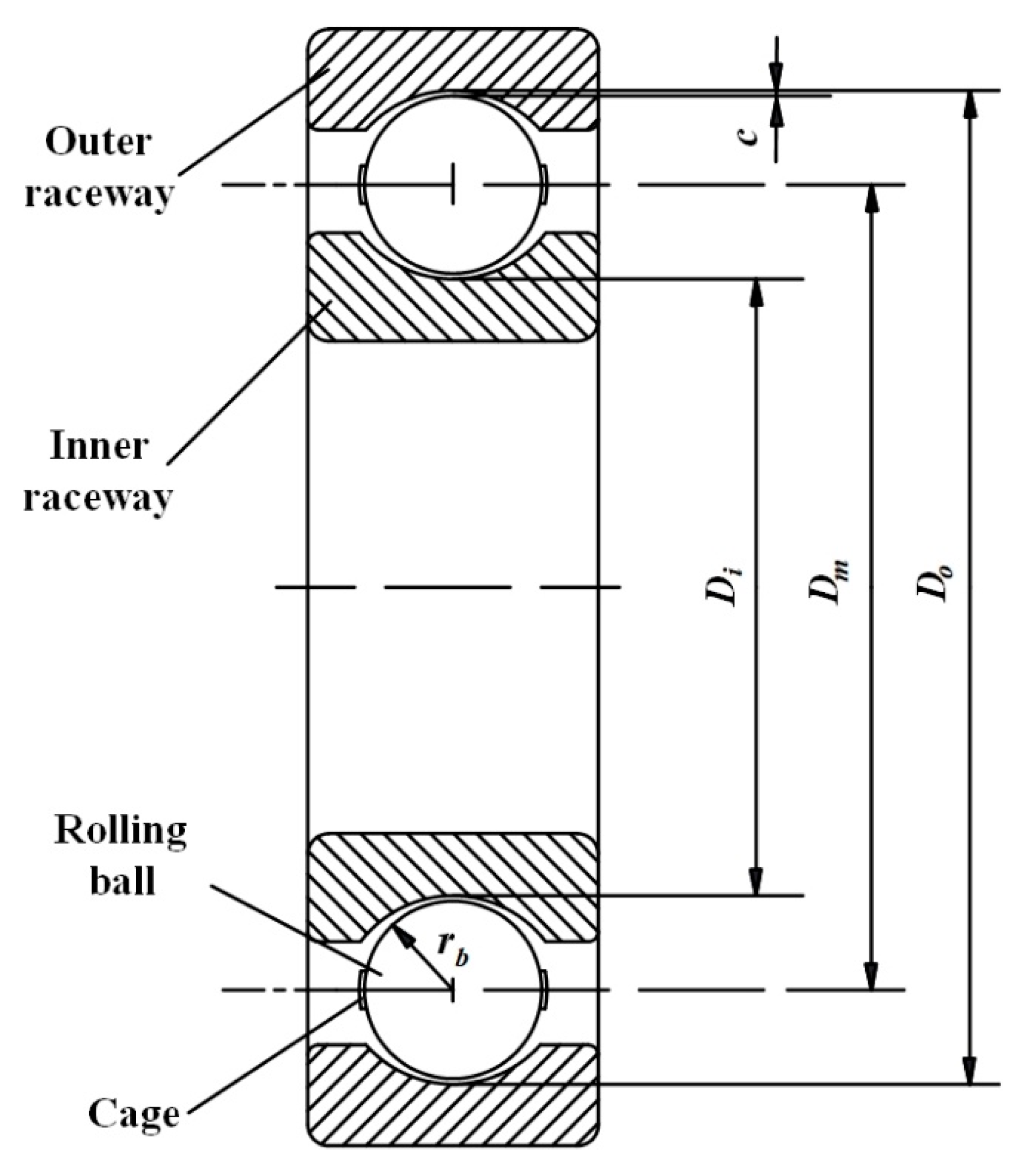
The clearance is a significant characteristic of a deep groove ball bearing, as shown in
Figure 1. According to the structural characteristics of the deep groove ball bearing, the contact point between the rolling ball and raceway bottom can easily be seen, and it can also be seen that the rolling ball moved in a radial direction, as shown in ref. [
4]. The model of a deep groove ball bearing can be simplified to a 2D model, which improves computational efficiency. Due to the existence of clearance, a rolling ball can move in different ways, and the impact phenomenon may cause the deformation of contact solids [
35,
36,
37,
38]. Then, the relationship between the clearance (
c) and the geometry characteristics of a ball bearing can be given as follows:
where
and
are the radii of the inner raceway and the outer raceway and
is radius of the rolling ball.
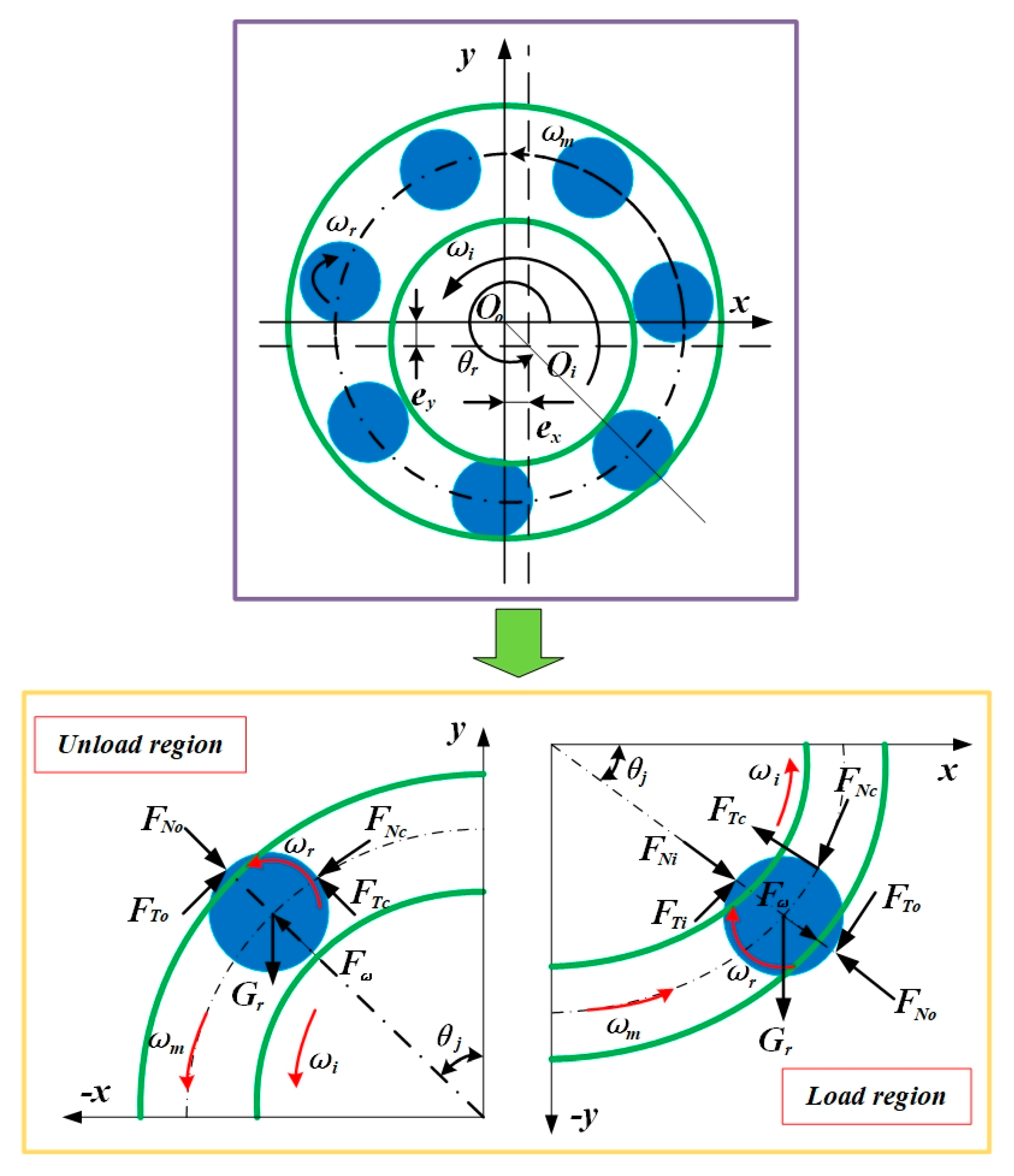
Figure 2 displays the movement connection of a ball bearing, and the velocities of a rolling ball’s center and its cage center can be, respectively, listed as:
where
denotes the length between the rolling ball’s center and the outer raceway’s center,
is the radius of the pitch circle, and
and
are the rotation and revolution angular velocities, respectively, of the rolling ball. The angle velocities of the rolling ball and the cage can be, respectively, calculated as:
where
is the rotation speed of the inner raceway, and
denotes the deformation of the inner raceway.
When the contact–impact phenomenon occurs, the deformation between the rolling ball and the raceway should be noticed, and these values of the inner raceway (
) and the outer raceway (
) can be, respectively, written as:
Then, the motion equations for the contact points of the inner raceway and the outer raceway can be, respectively, written as:
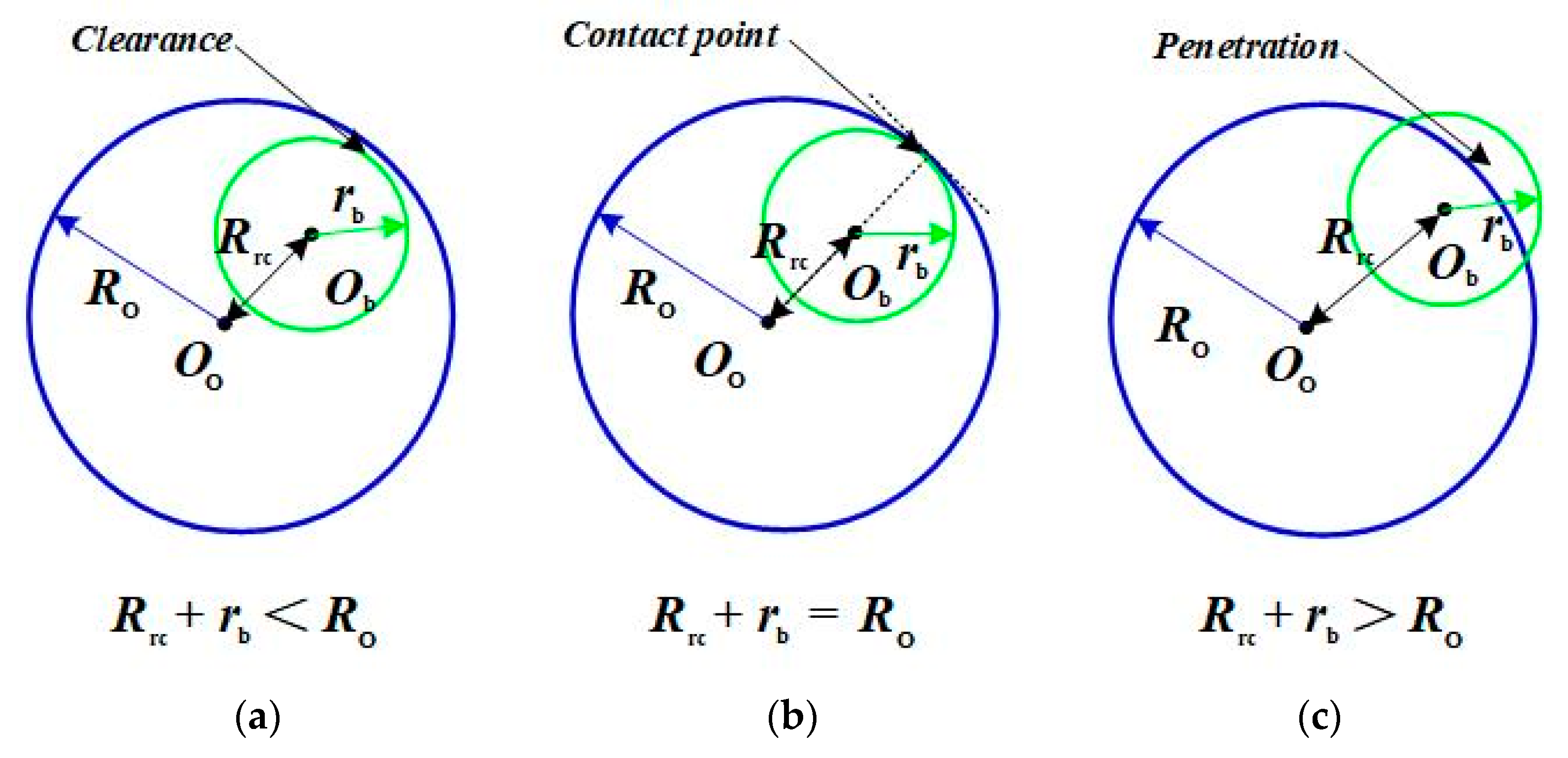
In addition, the clearance enlarges the active range of a rolling ball, and the various types of motion (free flight, contact, and impact) between the rolling ball and the raceway would occur, as displayed in
Figure 3. In the state of free flight, a rolling ball keeps away from the edge of a raceway. When the state of contact or impact appears, the reaction force would be represented between the rolling ball and the raceway [
39,
40,
41]. Then, the normal force (
) and tangential force (
) should be defined at the same time. As is well-known, the Hertz contact model is suitable for describing the elastic deformation, and it is widely used as a dynamic model for ball bearings, which is written as:
where
K is the stiffness coefficient of the contact elements.
However, it is easily found that the Hertz contact model only illustrates the relationship between the contact force and the deformation, and the energy dissipation is ignored in the equation. It is widely known that energy dissipation would happen during the contact–impact process of the solids, which can change the motion trajectory of the contact elements [
42,
43,
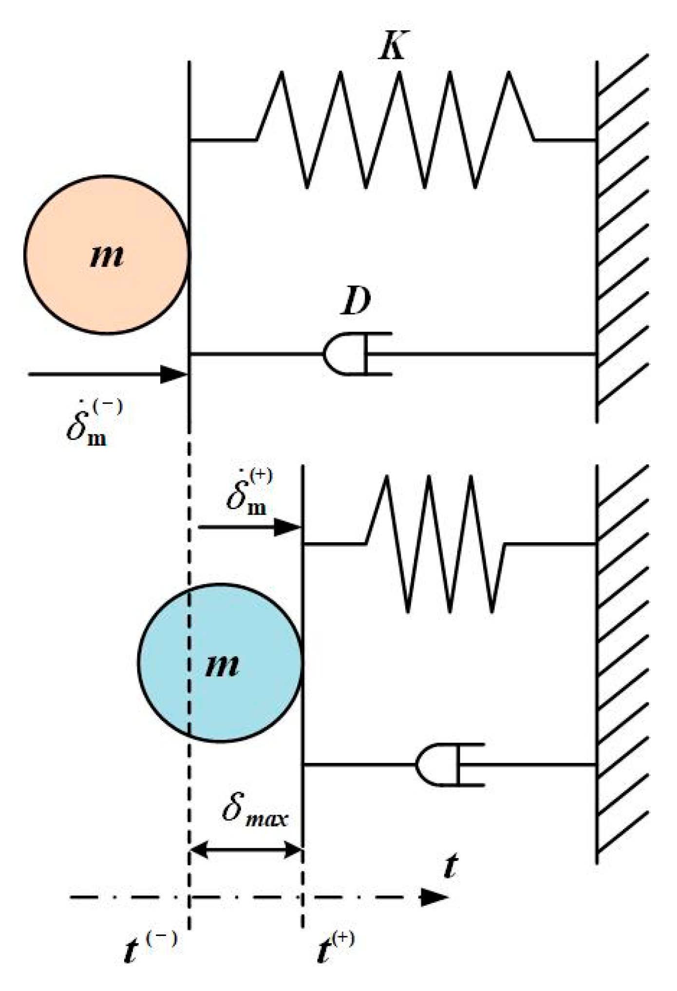
44]. Lankarani and Nikravesh proposed a dissipative contact force model to illustrate the contact–impact characteristics of solids. It is well known that the value of the energy dissipation can be obtained using the damping terms and deformations of the contact elements, and the formulation of the contact force is given as [
45]:
where
D represents the hysteresis damping coefficient, which transfers the energy dissipation (kinetic energy) to the value of the spring damp (in
Figure 4). The subscript (
l) represents the contact element during the motion and
i,
o, and
c are the inner raceway, the outer raceway, and the cage, respectively. This model (the L–N model) is more suitable for revealing the contact–impact characteristics of the contact elements. The stiffness coefficient (
) and hysteresis damping coefficient (
D) are, respectively, defined as:
where
and
are the parameters of the material characteristics,
e denotes the restitution coefficient, and
represents the initial impact velocity.
Meanwhile, the modified Coulomb’s friction law was employed to represent the friction force (in the tangential direction), which is described as [
46,
47,
48]:
where
is the friction coefficient,
represents the relative tangential velocity,
sgn(·) denotes the symbolic function, which is related to the sign of a parameter (positive or negative), and
is the dynamic correction coefficient, which is obtained as:
where
and
represent the given tolerances for the tangential velocity of surfaces during contact.
According to the characteristics of the kinematics and dynamics, the motion relationship of a ball bearing rolling ball could be satisfied with the conditions in the different regions [
49,
50]. In the unload region, the rolling ball would move outwards by centrifugal force (
) and the contact point would appear between the rolling ball and the outer raceway, and the dynamic equations are depicted as:
where
Fc is the friction force of the cage, which is related to the mass and the moment of inertia for the cage,
denotes the gravity force,
is the moment of inertia of the rolling ball, and
is the time differential of the variable
u.
Moreover, the rolling ball could contact the inner raceway and the outer raceway in the load region [
51,
52]. Then, the dynamic equations can be assembled as:
where
is the position angle of the
jth ball.
3. Experiment Study and Demonstration
The experiment study is an important part of a dynamic behavior analysis for a deep groove ball bearing. Based on the investigation of the ball bearing experimental method, an external load is usually defined as the value for conducting a dynamic response experiment [
22,
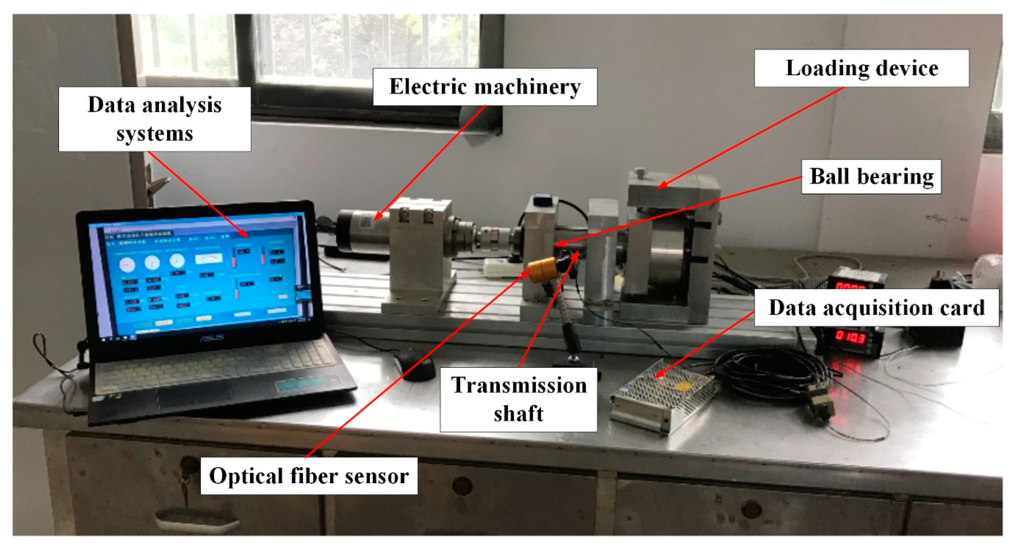
52]. The configuration of the test platform is shown in
Figure 5, and it satisfied the requirements for the various operation conditions (i.e., external load and rotation speed). The electric machinery was installed in the test platform, and it turned on the ball bearing using the transmission shaft. The optical fiber sensor was located in the fixed bracket, and it recorded the rotational speed of the cage. Moreover, the external load was obtained by the loading equipment, and it was applied in the inner ring of the deep groove ball bearing. Based on the data acquisition card, the test data of the deep groove ball bearing were collected. Then, the data analysis systems could represent the relationship between the rotation speed of the cage and the external load. In the validation study, the external load was defined as a variable, and the values of the cage were collected at the same time. In order to maintain the effectiveness of the test data, the experimental result was provided by the average value of five repetitions in the same conditions.
The test ball bearing used was an SKF 6304, and its parameters are listed in
Table 1. The rolling ball, cage, and raceway were made of steel (GCr15), and the hardness of the rolling ball was slightly more than that of the cage and the raceway. An elastic deformation often occurred in the cage and the raceway. Based on [
52] and the SKF product manual, the clearance size of an SKF 6304 is divided into five levels, and 0.005 mm belongs to C2. It is known that the external load and contact pressure are factors in the dynamic response of a deep groove ball bearing. Due to the limitations of the experimental platform, only the external load was employed for the changed working conditions. Moreover, only the deep groove ball bearing included grease, and the hydrodynamic effect of a lubricant is incapable in this condition. The condition of dry friction was defined in the simulation model [
1,
8].
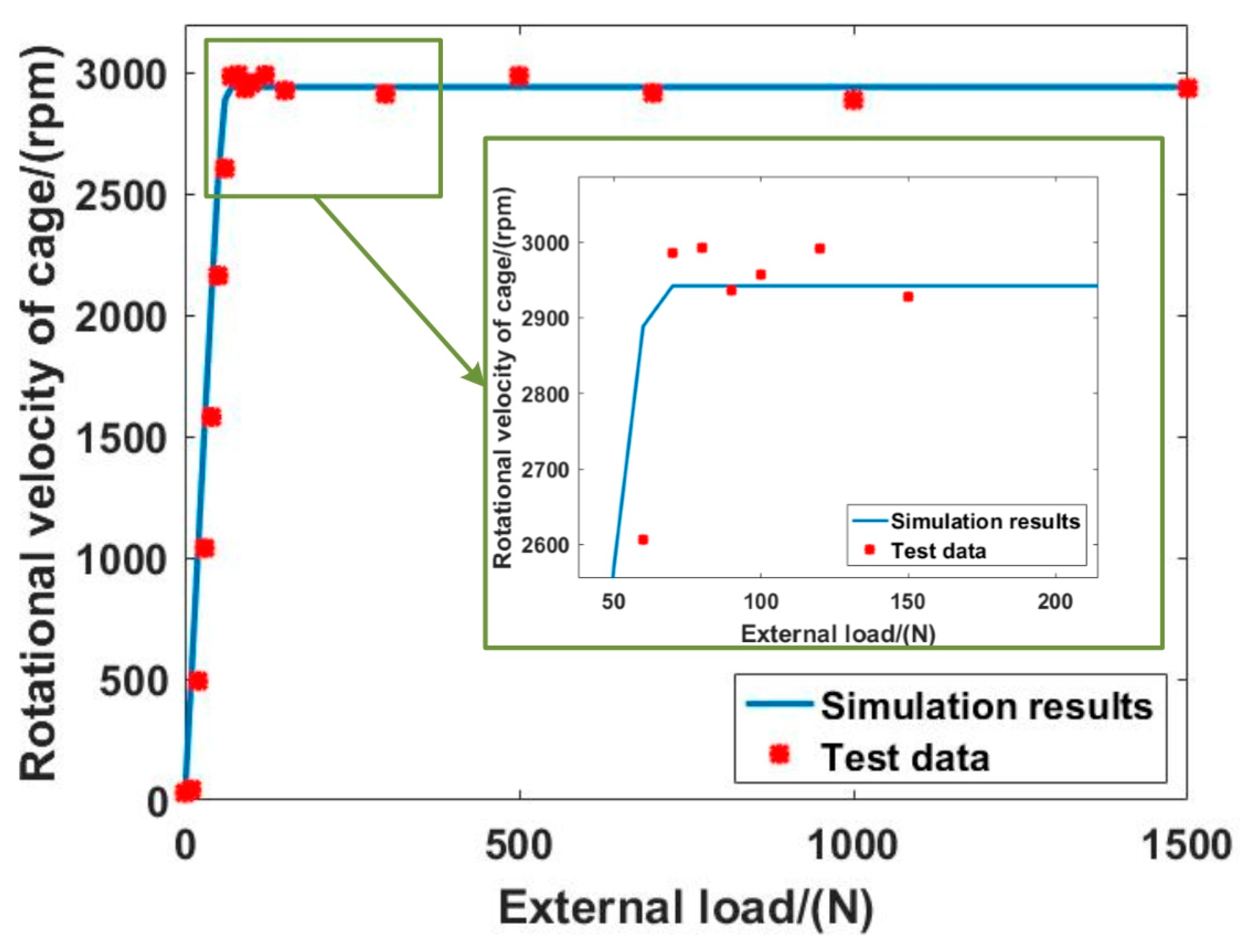
The running speed of the electric machinery was increased up to 8000 rpm, and the external load increased from 0 N to 1500 N. The comparison results are shown in
Figure 6, and the fluctuations in the test data were smaller under the same conditions. It was noteworthy that the mass of the deep groove ball bearing caused a load on the shaft. Although this value of 30 rpm was small, the applied force changed the rotational velocity of the cage under the condition of 8000 rpm and a 0 N external load. As the rotation speed for the drive device increased, the rotation velocity of the cage also increased. However, the rotation speed of the cage ceased to increase under external loads that exceeded 70 N. Then, this value fluctuated slightly at approximately 2940 rpm. It was noteworthy that the simulation results of the proposed method had similar dynamic characteristics under the same conditions. The maximum deviation between the test data and the simulation results was only 4.24%, which is acceptable for engineering problems. The presented method could acceptably evaluate the dynamic characteristics of deep groove ball bearings.
4. Results and Discussion
The dynamic characteristics of deep groove ball bearings are the most concerning issue in their design. The contact–impact phenomenon is unavoidable during the running state, and this feature would be represented in various forms in the different motion regions. Moreover, variations in the operation conditions and structural features can also change the dynamic response of a deep groove ball bearing. In order to reveal the correlation between the design parameters and the nonlinear dynamic behaviors, the contact characteristics and movement trajectory of a deep groove ball bearing are discussed.
4.1. The Effects of Rotation Speed and External Load
Whether the stability of a deep groove ball bearing is satisfied by the requirements of its design depends on the dynamic response of the ball under different operation conditions. The structural parameters of deep groove ball bearings are such that number of the rolling ball is seven and its clearance size is 0.005 mm. In order to represent the impact of the operation conditions on the dynamic response of a deep groove ball bearing, the rotation speed and external load are varied. When the external load is 100 N, the rotation speeds are defined as 2000 rpm, 4000 rpm, 8000 rpm, and 15,000 rpm. In addition, when the rotation speed is defined as a constant value of 8000 rpm, the variation range of the external load is from 30 N to 1000 N.
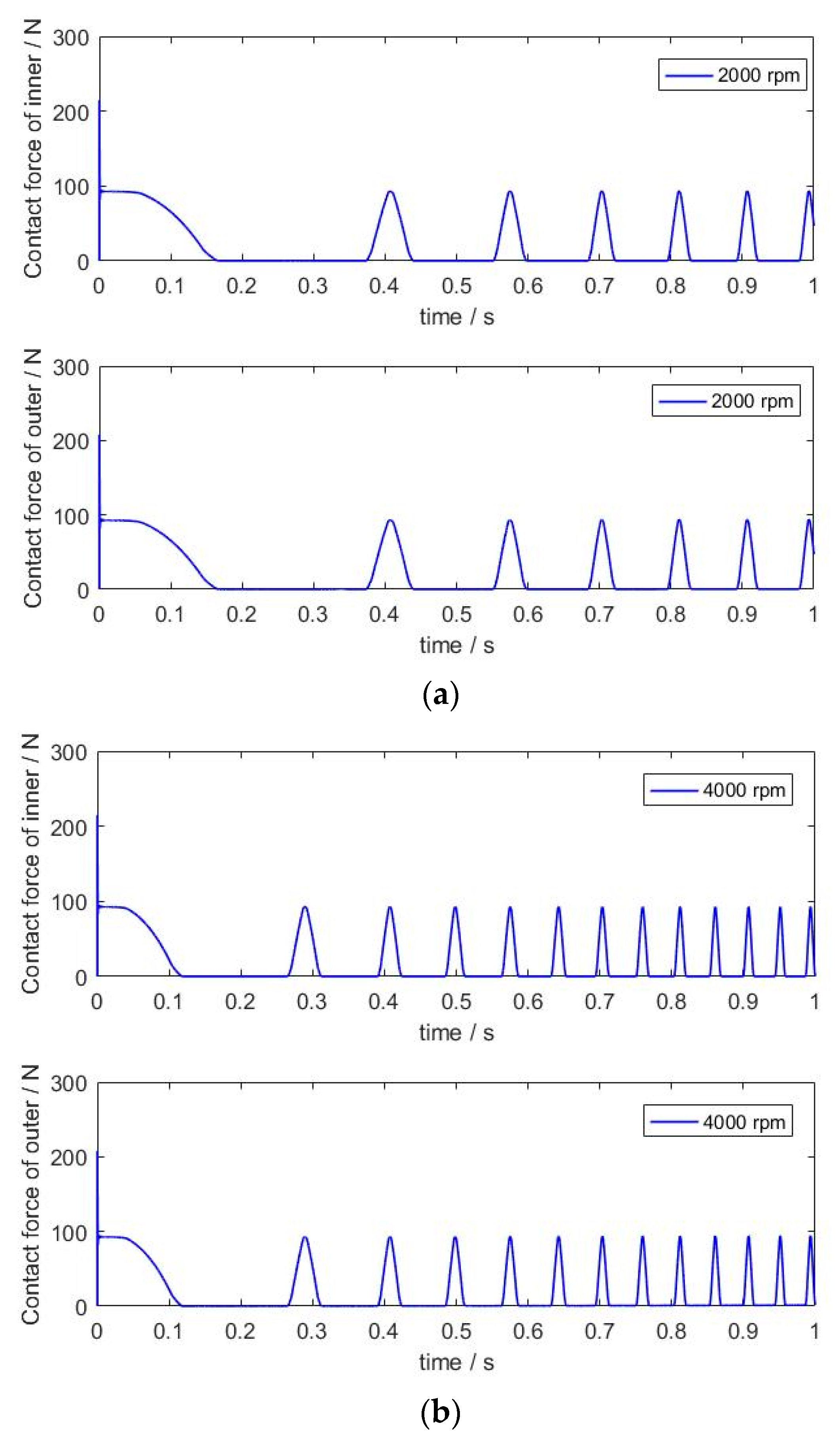
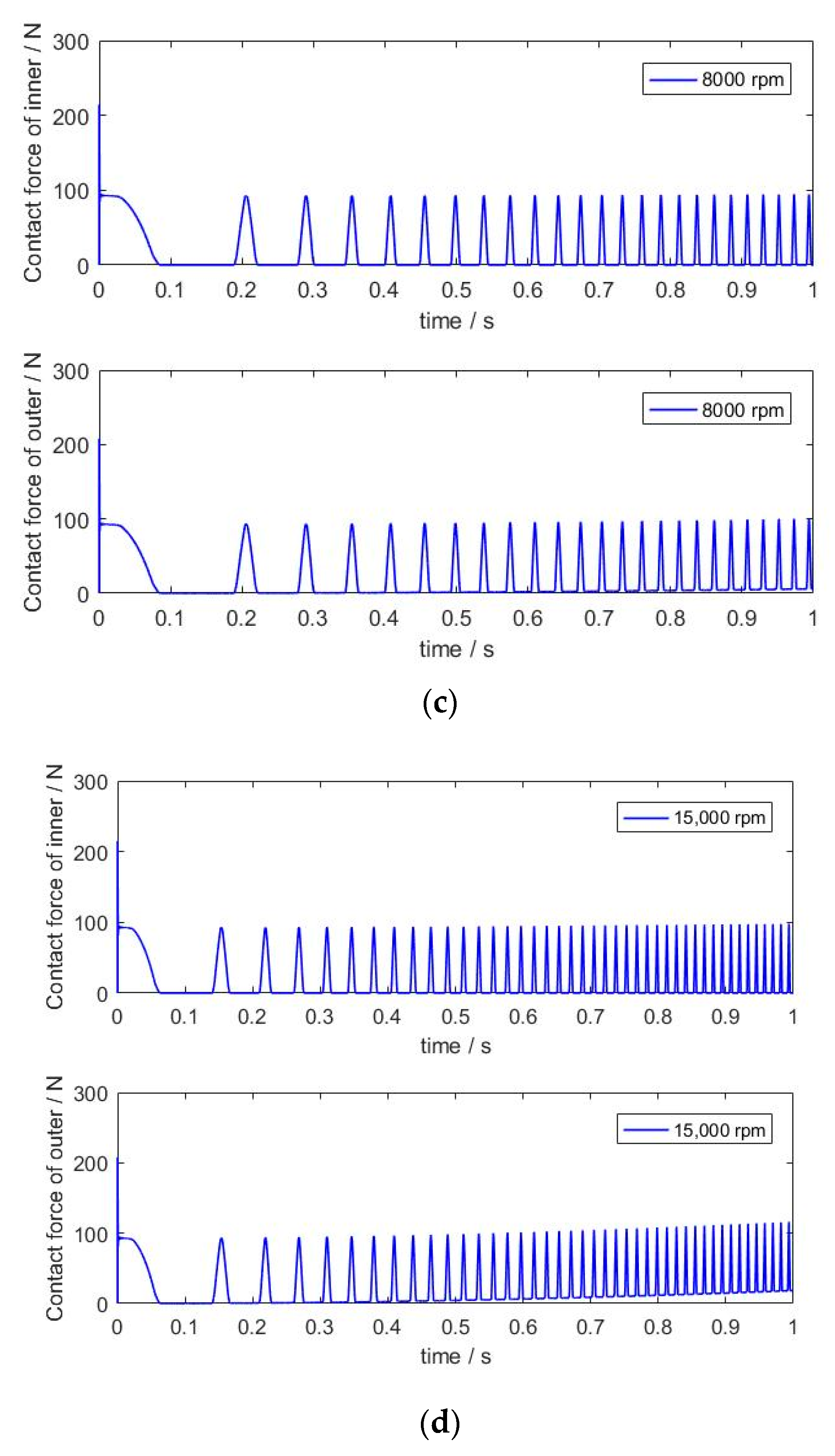
Figure 7 shows the contact characteristics of the rolling ball and the raceway at different rotation speeds with an external load of 100 N. It is clear that growth in the rotation speed can increase the collision frequency, which would cause the deep groove ball bearing to vibrate. Although the maximum contact force of the inner raceway maintained a similar value, a larger rotation speed would increase the growth in the contact force for the outer raceway. It was noteworthy that the contact time was evidently shortened and there was a larger impact inertia that appeared at the same time, which is disadvantageous for maintaining the stable state of a deep groove ball bearing. Moreover, was interesting that the contact force of the outer raceway did not reach 0 N when starting with approximately 0.5 s of simulation time. In
Figure 7c,d, the centrifugal forces increased with the growth in the rotation speed. Then, the larger centrifugal forces pushed the rolling ball outward and the d’Alembert inertial forces increased at the same time, which kept the balance with the contact forces of the raceways. When the ball entered the load region, the free flight state between the ball and the inner raceway disappeared. However, the reaction force of the outer raceway remained at the required center force of the high-speed rotation for the rolling ball. The friction force was obtained by the contact force. In the early acceleration stage of motion, the stronger oscillation of the contact force would change the value of the friction force, which was the main reason for the unstable movement of the rolling ball. Meanwhile, the appearance of the abrupt change was caused by the slipping phenomenon of the rolling ball. With the end of the acceleration motion state, the effects of the rotation speed on the contact characteristics were evident. The growth in the rotation speed accelerated the changes in the centrifugal force and the contact frequencies of the rolling ball and the raceway. The effects of the external load on the contact characteristics are displayed in
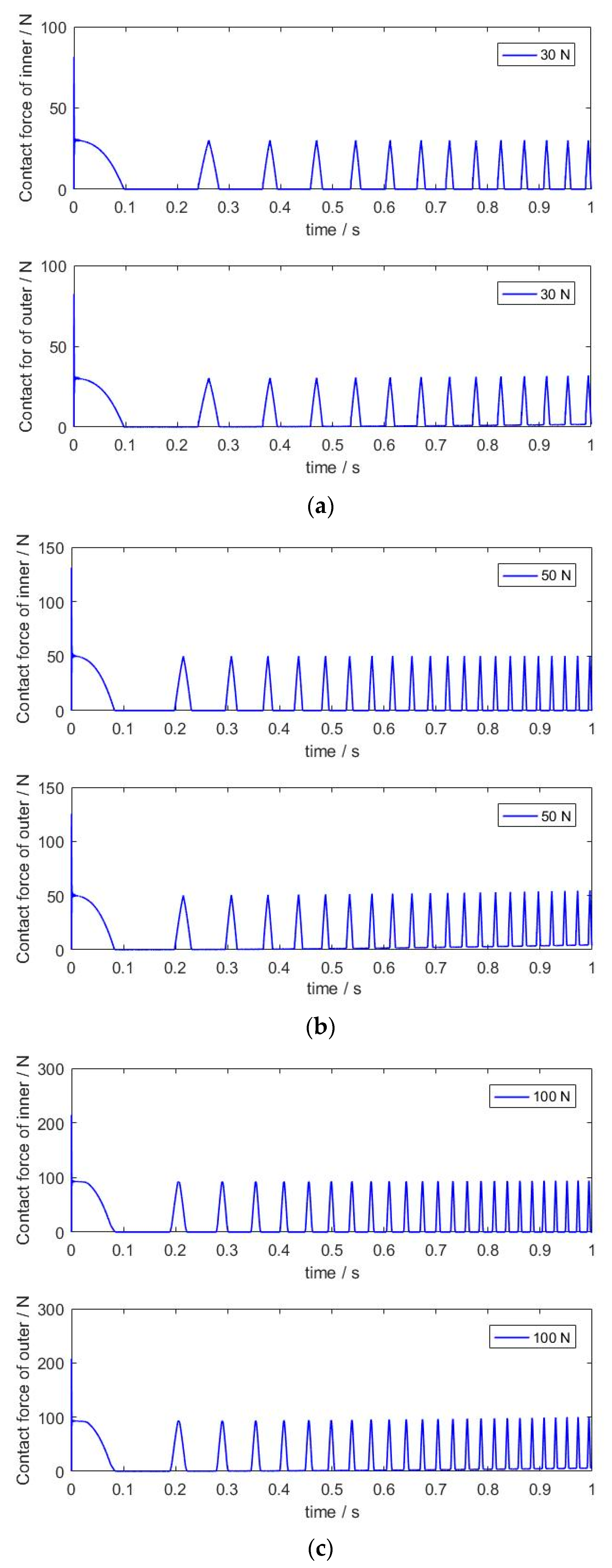
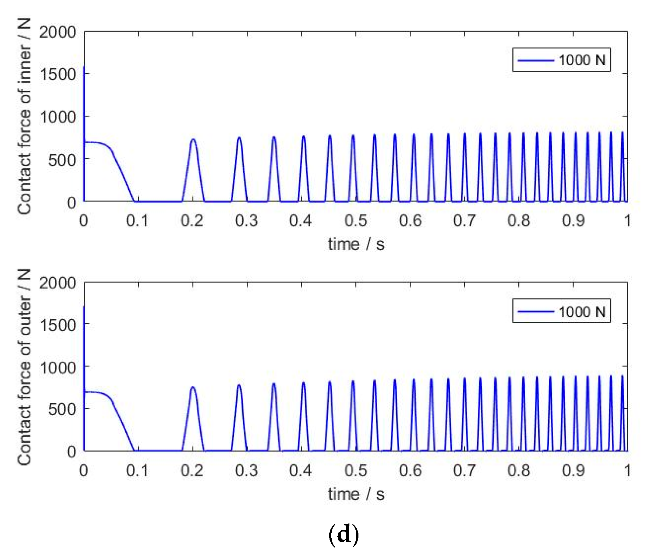
Figure 8a–d, and the rotation speed was chosen to be 8000 rpm in the simulation. The increase in the external load caused a stronger contact–impact phenomenon, which explained why the growth in the external load could restrain the slipping of the rolling ball.
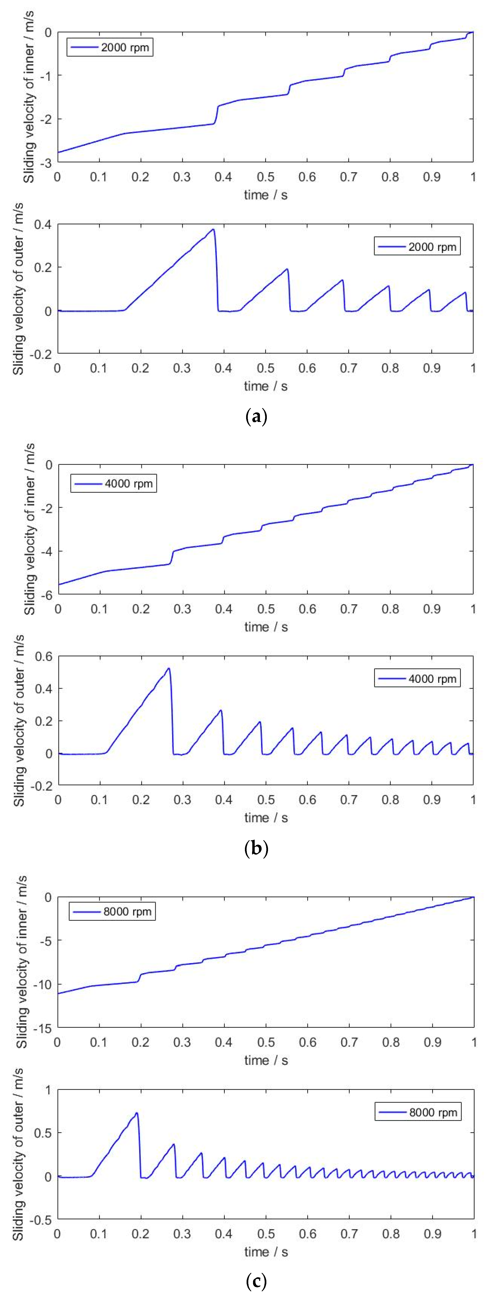
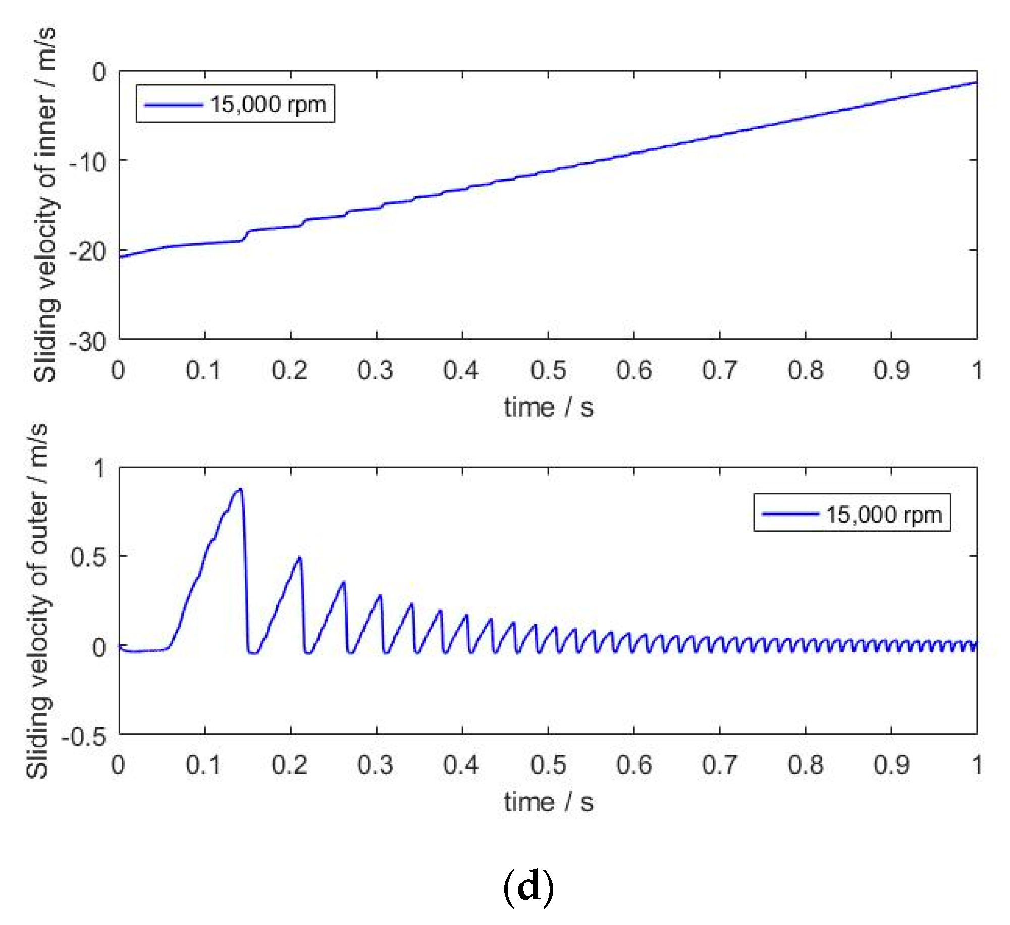
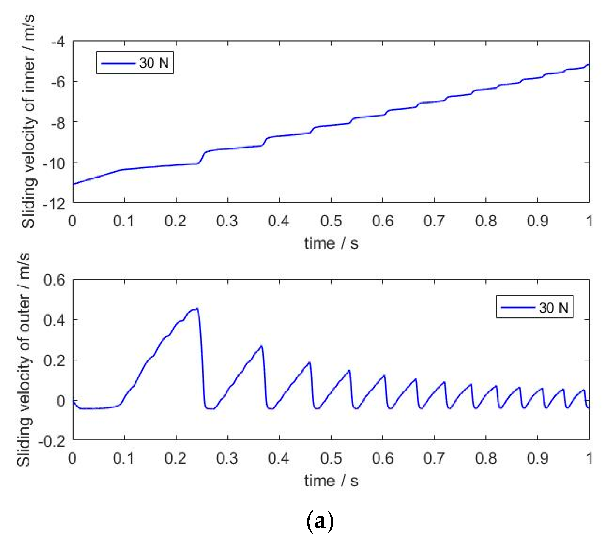
With a constant external load of 100 N,
Figure 9 represents the influence of the rotation speed on the sliding velocity between the rolling ball and the raceway. As the rotation speed of the inner raceway rose, the value of the sliding velocity for the inner raceway and the fluctuation period increased, which is clearly shown in
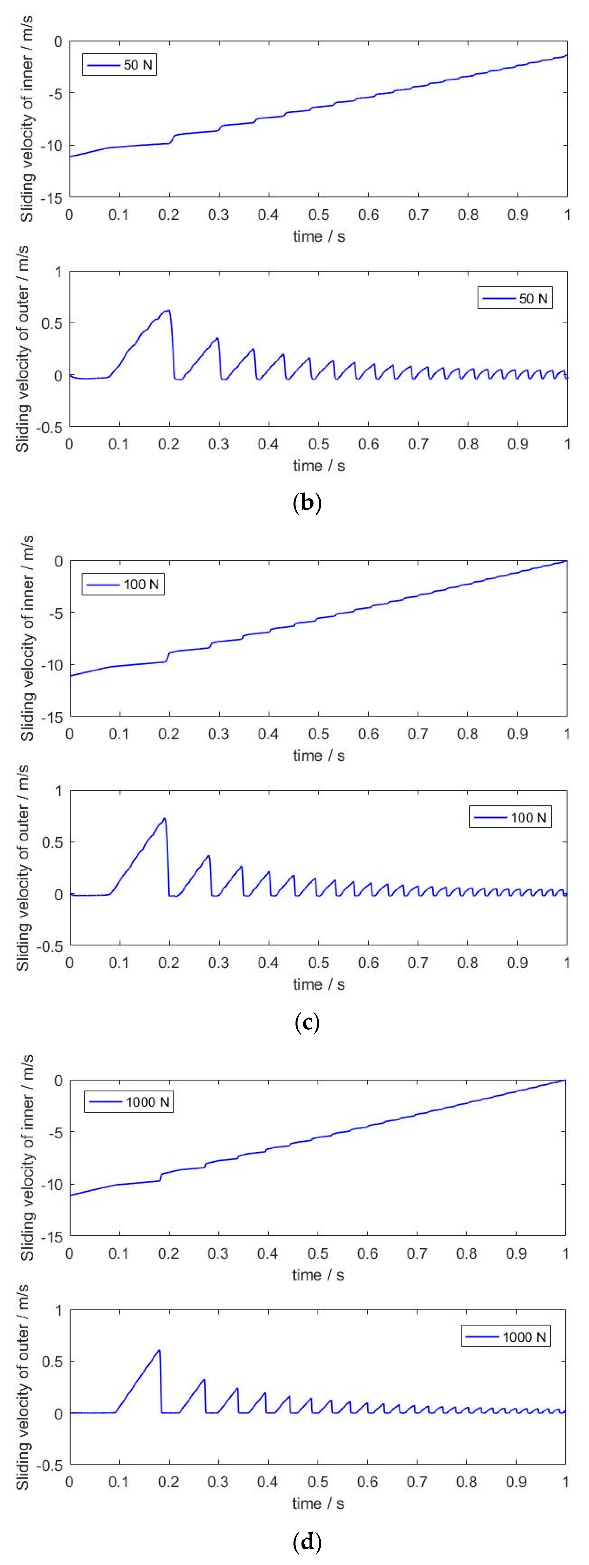
Figure 9c,d. Meanwhile, the sliding velocity of the outer raceway had similar variation characteristics, and the increase in the attenuation frequency caused a slight decline in the sliding velocity. A higher speed in the inner raceway accelerated the rotation speed of the rolling ball, and a lighter external load could not maintain the related speed between the rolling ball and the cage, which was the immediate cause of the sliding phenomenon. When the rotation speed was 8000 rpm, the increase in the external load relieved the slipping phenomenon of the rolling ball, as shown in
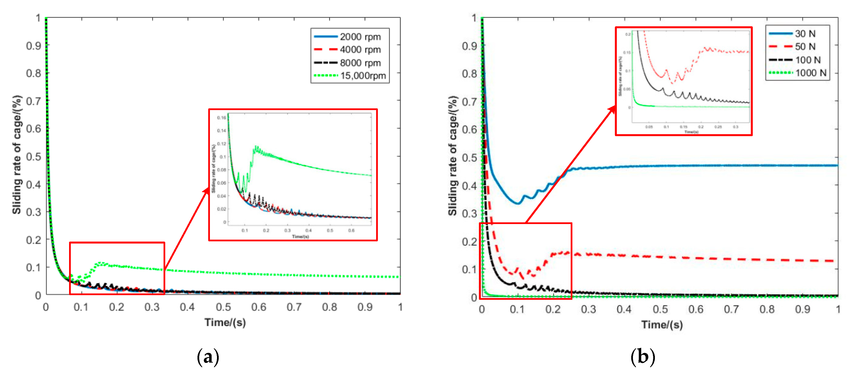
Figure 10a–d. Furthermore, the growth in the rotation speed changed the value of the sliding rate for the cage, and it extended the time required to reach the stable time, as shown in
Figure 11. When the rotation speed reached 15,000 rpm, the strong vibration and rebound feature of the sliding rate for the cage appeared, as seen in
Figure 11a. According to the results, it was clear that a larger external load could quickly keep the movement of the cage within a stable state, and the sliding rate of the cage was small, as seen in
Figure 11b. As is well-known, a higher sliding rate of the cage could reduce the working efficiency rate. We noted that the larger preload would be defined in the high-speed working condition, which could provide a better dynamic response of the deep groove ball bearing.
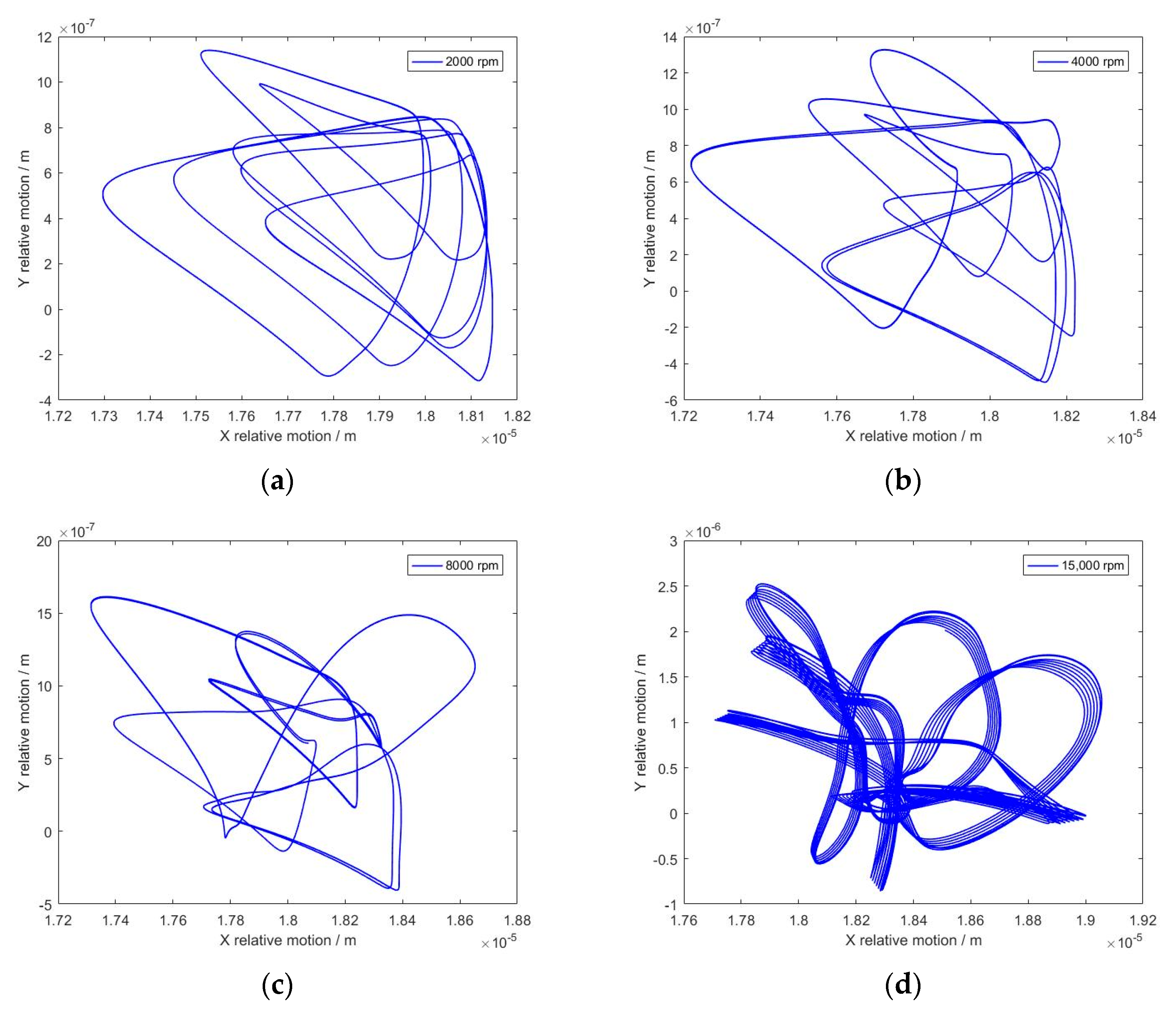
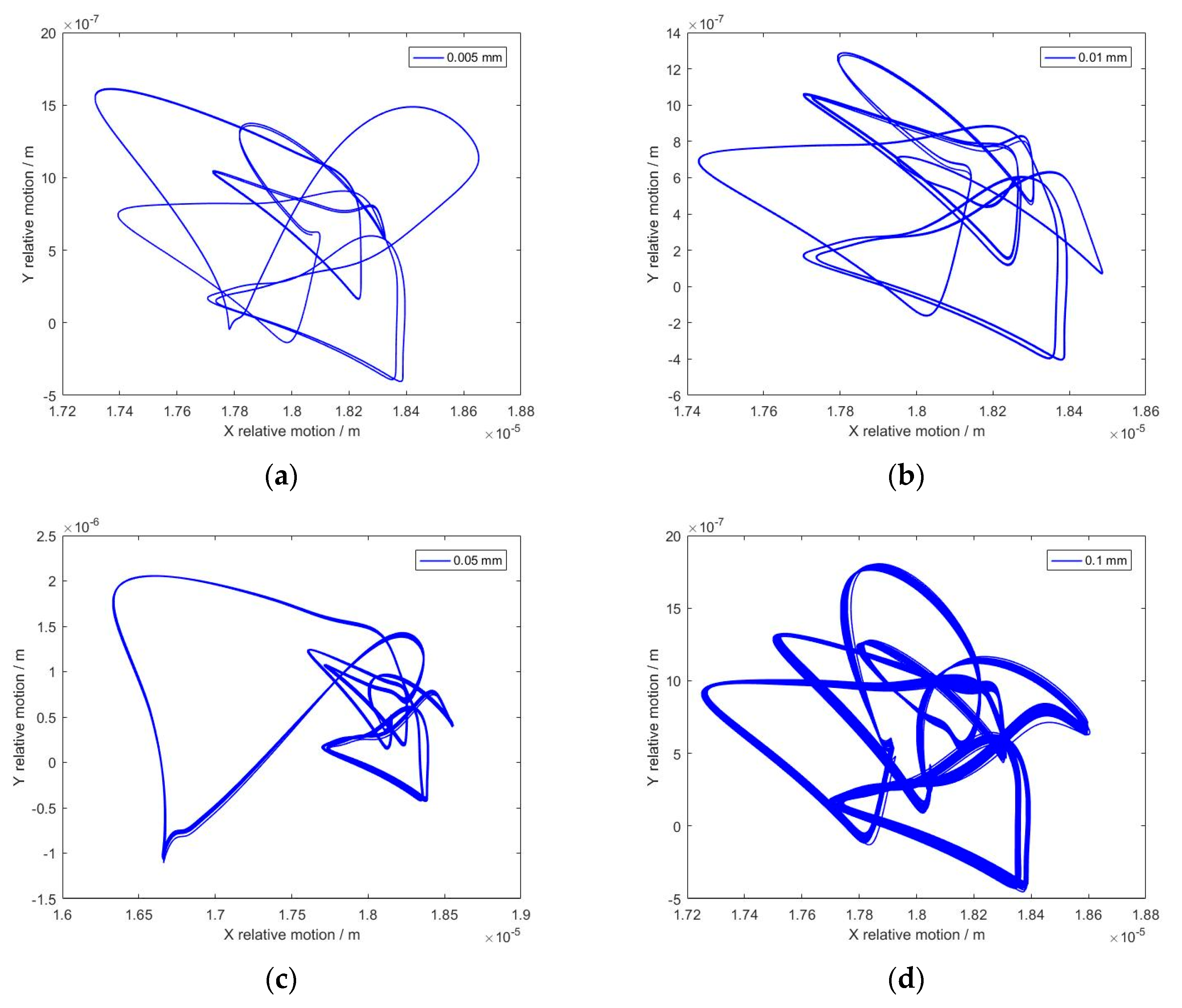
The center trajectory of the inner raceway is closely related to the movement state of the deep groove ball bearing, as shown in
Figure 12 and
Figure 13. With the same external load (100 N), the lower rotation speed would provide the periodicity of the motion trajectory and the inner raceway would maintain the same path, which is the stable dynamic response of a deep groove ball bearing. However, the motion trajectory of the inner raceway changes as the rotation speed increases. When the rotation speed exceeded 8000 rpm, the bifurcation and quasi-periodic characteristics became more serious, as shown in
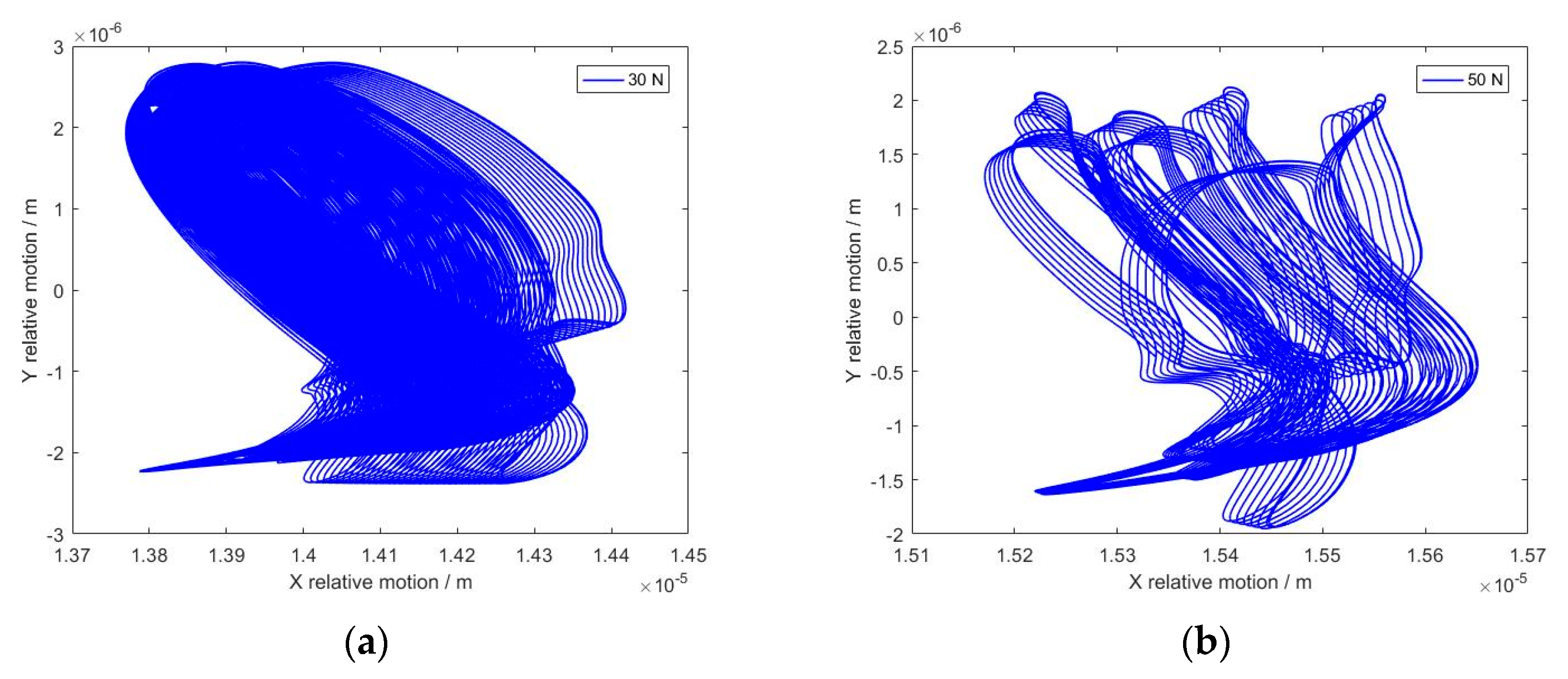
Figure 12d. Then, the inner raceway moved along different routes under this condition. The center trajectory of inner raceway was not unique, and many similar routes appeared at 15,000 rpm. It was easily found that the increase in the movement speed of the rolling ball caused the variations in the impact velocity, and the contact characteristics (deformation and energy dissipation) would have changed at the same time. Furthermore, the contact characteristics are closely related to the center trajectory of the inner raceway. In addition, the effects of the external load on the center trajectory of the inner raceway are diverse, and the rotation speed was defined at a constant value (8000 rpm), as shown in
Figure 13. It was clear that the many similar center trajectories of the inner raceway appeared and the bifurcation was evident, as seen in
Figure 13a. As the external load increased, the chaos phenomenon of the center trajectory for the inner raceway was controlled and the motion path of the inner raceway became clear. The growth in the external load reduced the movement region of the rolling ball, which was also the reason for the regular movement of the inner raceway. These results also illustrate that the growth in the external load would be advantageous for the stable movement of a deep groove ball bearing, and the preload of a deep groove ball bearing could be defined at a larger value.
According to the simulation results, it could be found that the rotation speed had a significant effect on the contact–impact process. The contact frequency and decay speed of the friction force evidently changed as the rotation speed increased. A higher rotation speed would cause a serious sliding phenomenon and the rebound characteristics of the sliding rate for the cage could appear. However, a larger external load would stop this phenomenon. Then, the analysis of the operation condition would provide helpful insights for the design of the production application table.
4.2. The Effects of Clearance Size and Rolling Ball Number
The variations in clearance size would change the movement region of the rolling ball, and the number of the rolling ball could determine the location of the contact position. Then, the clearance size and number of the rolling ball can be chosen to align with the variables. The operation condition was defined such that the rotation speed of the inner raceway was 8000 rpm and the external load was 100 N.
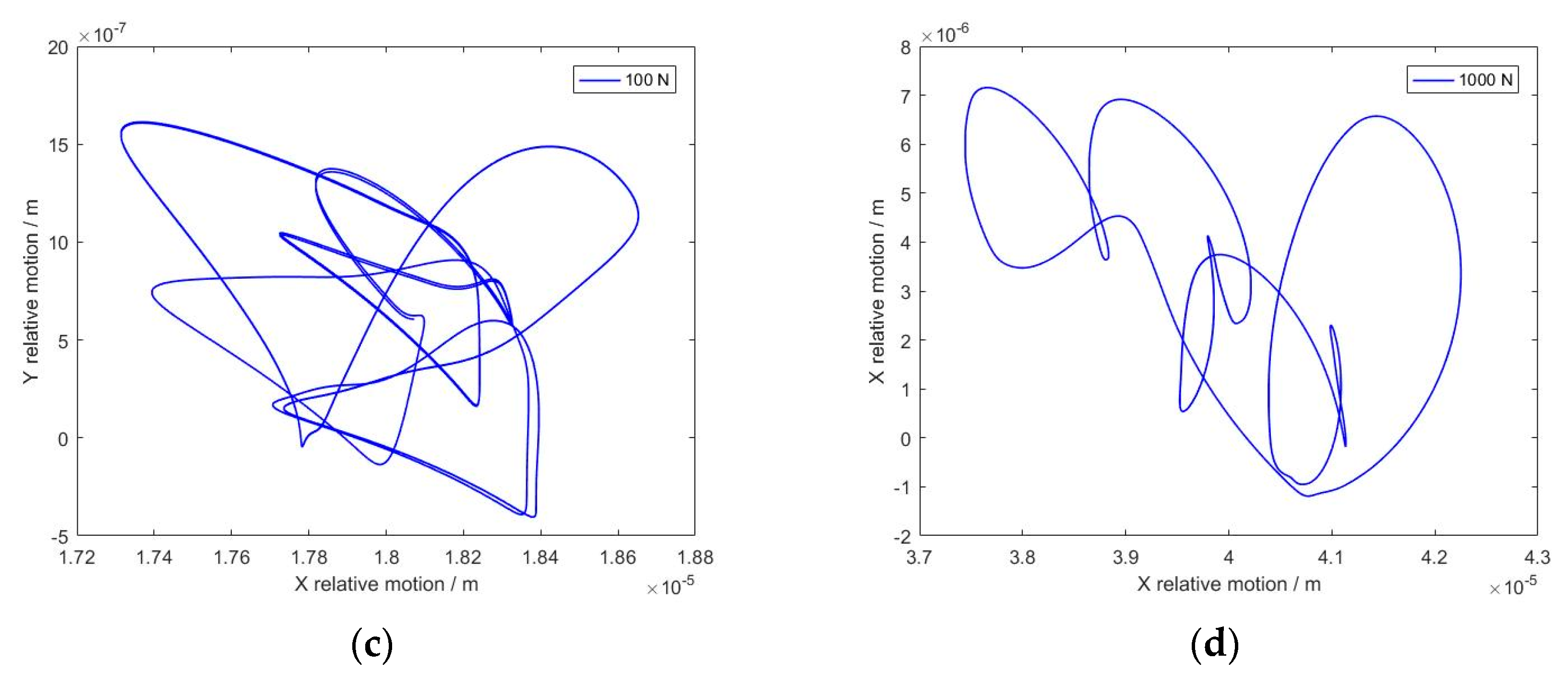
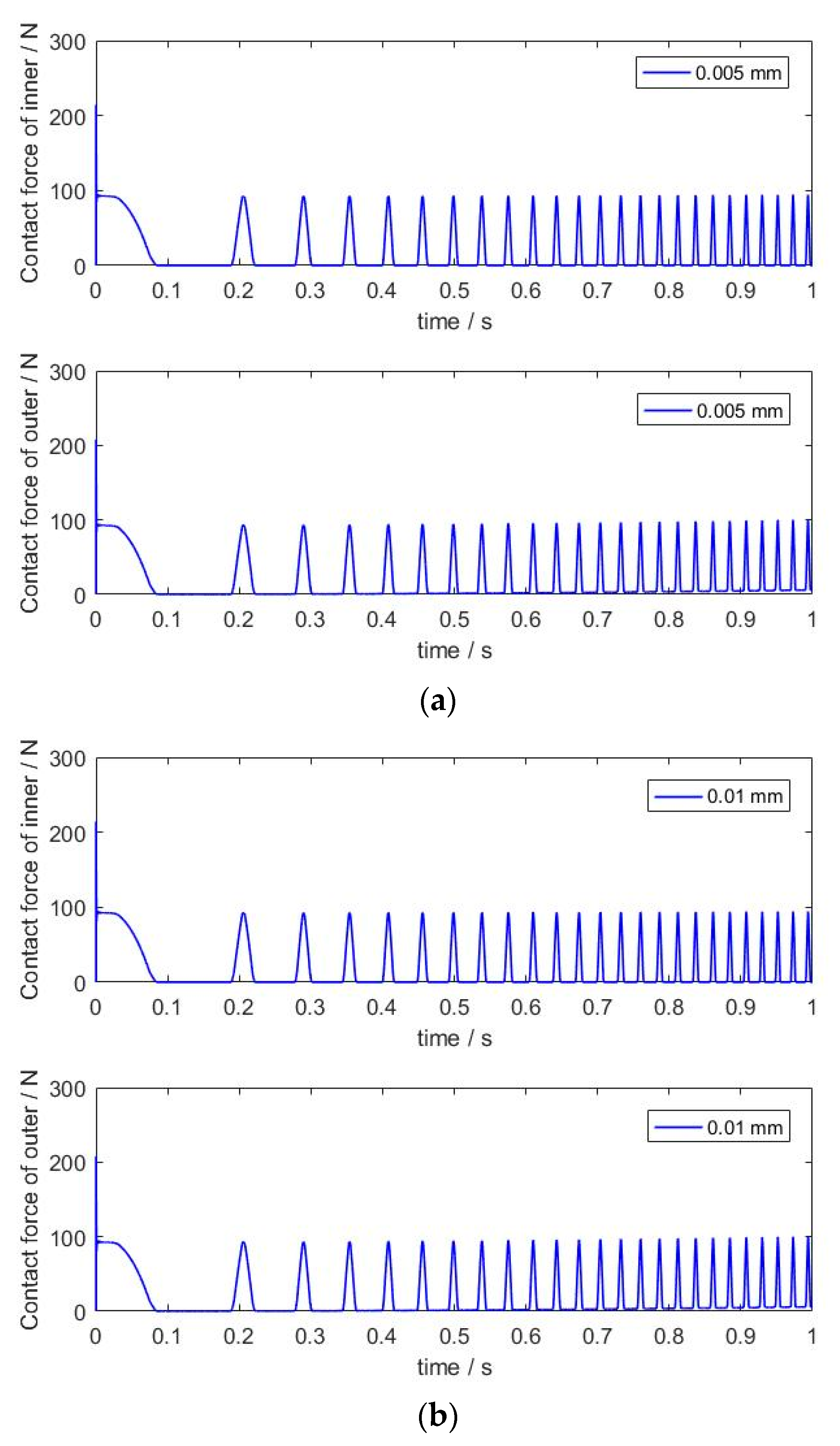
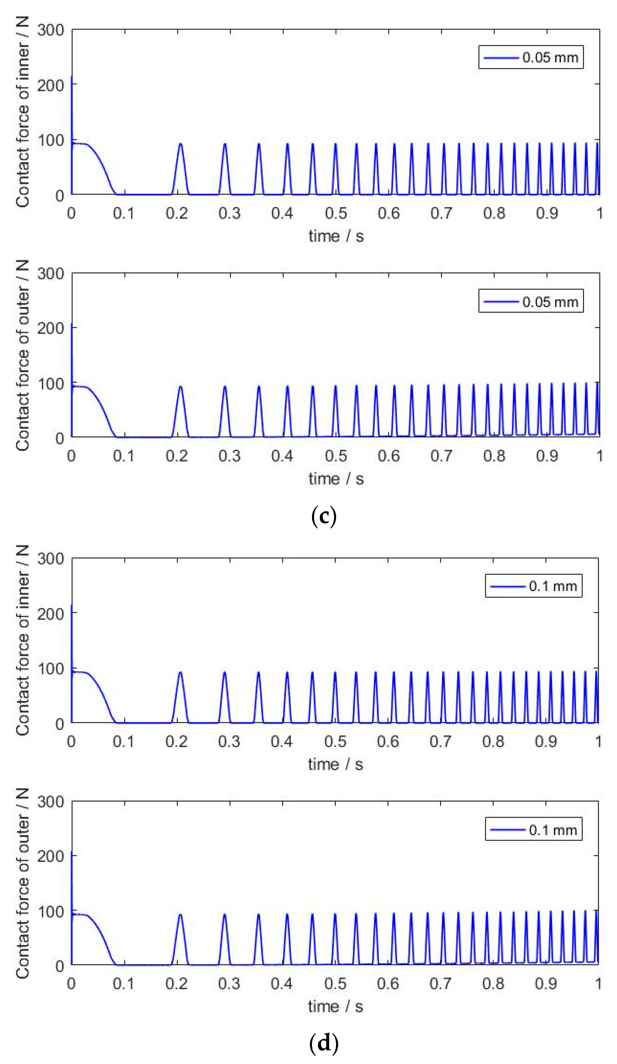
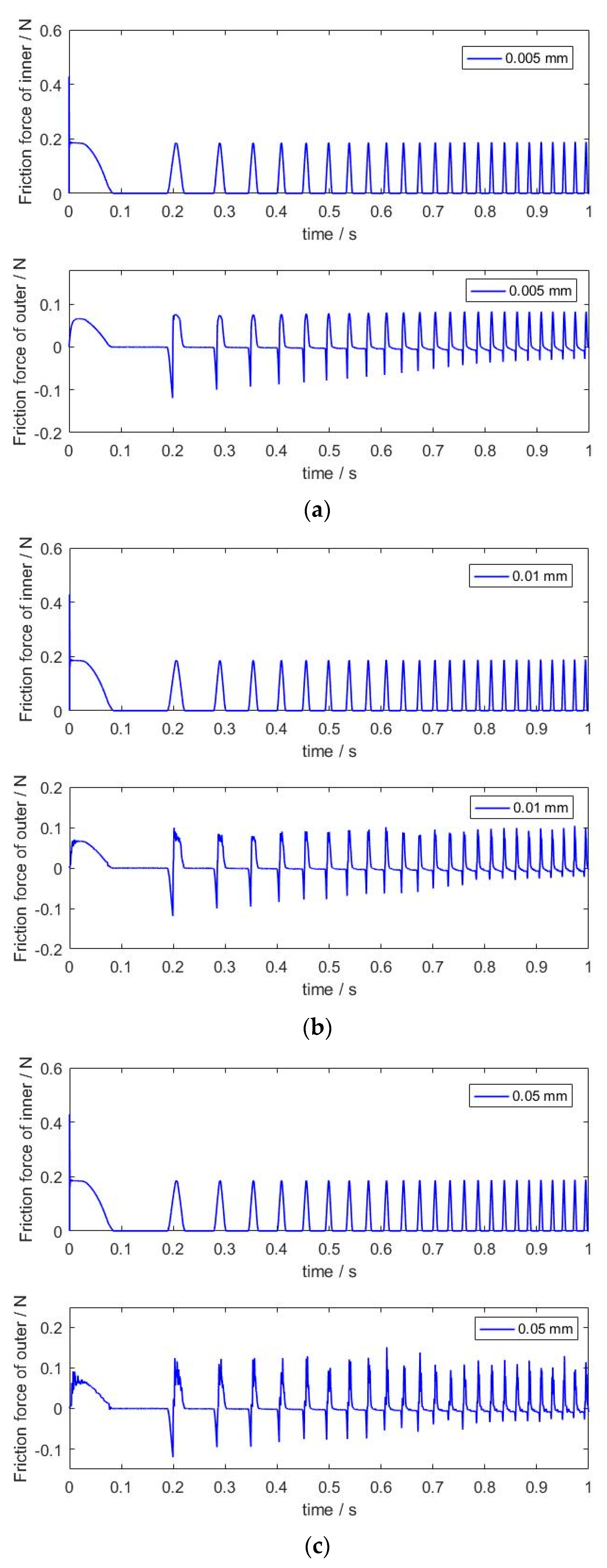
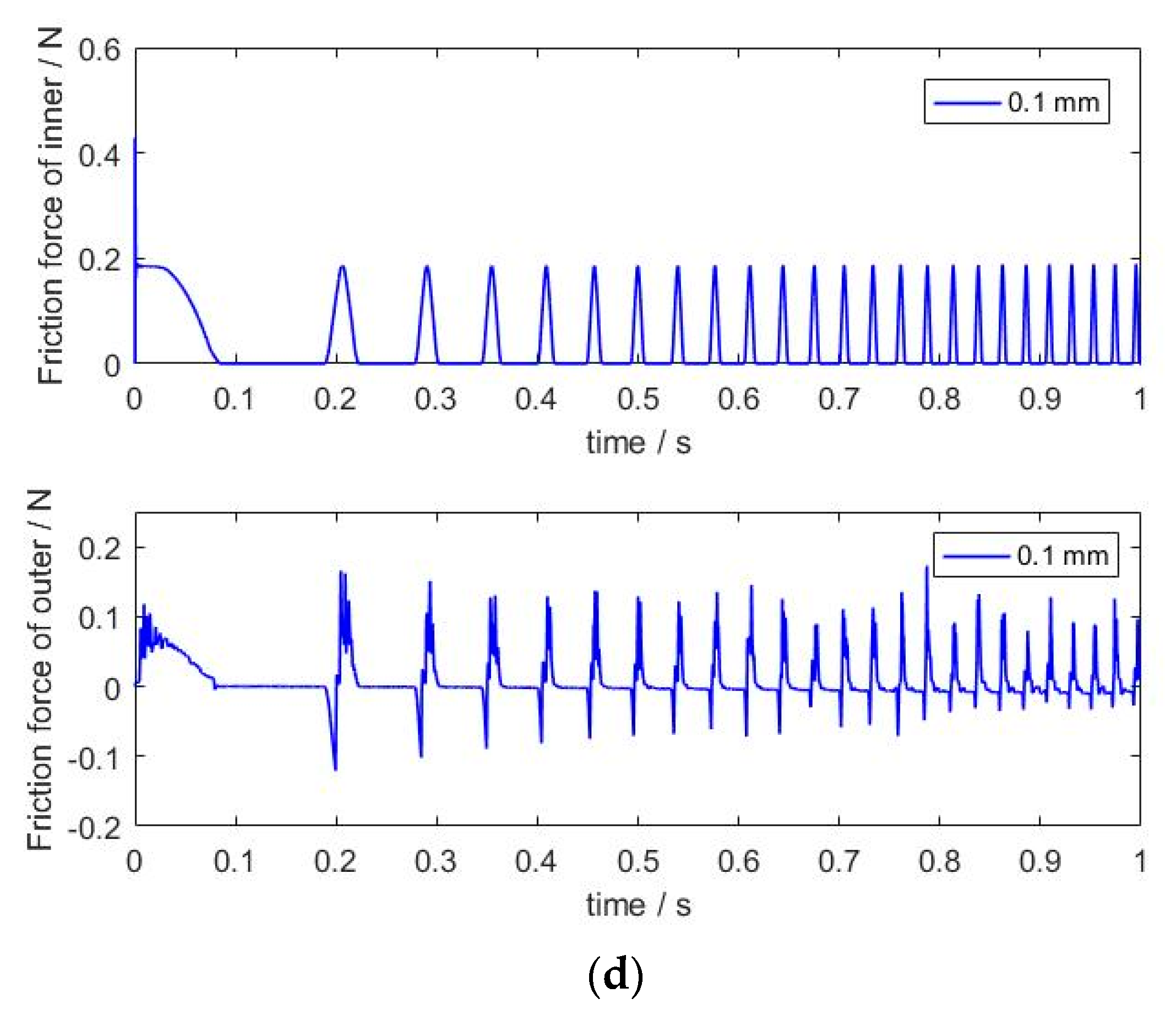
Figure 14 displays the effects of clearance size on the contact characteristics of deep groove ball bearings. When the number of the rolling ball is seven, the clearance size increases from 0.005 mm to 0.1 mm. In
Figure 14c,d, the contact characteristics of the outer raceway with a larger clearance size are more evident and the phenomenon of the continuous contact occurred earlier. As shown in
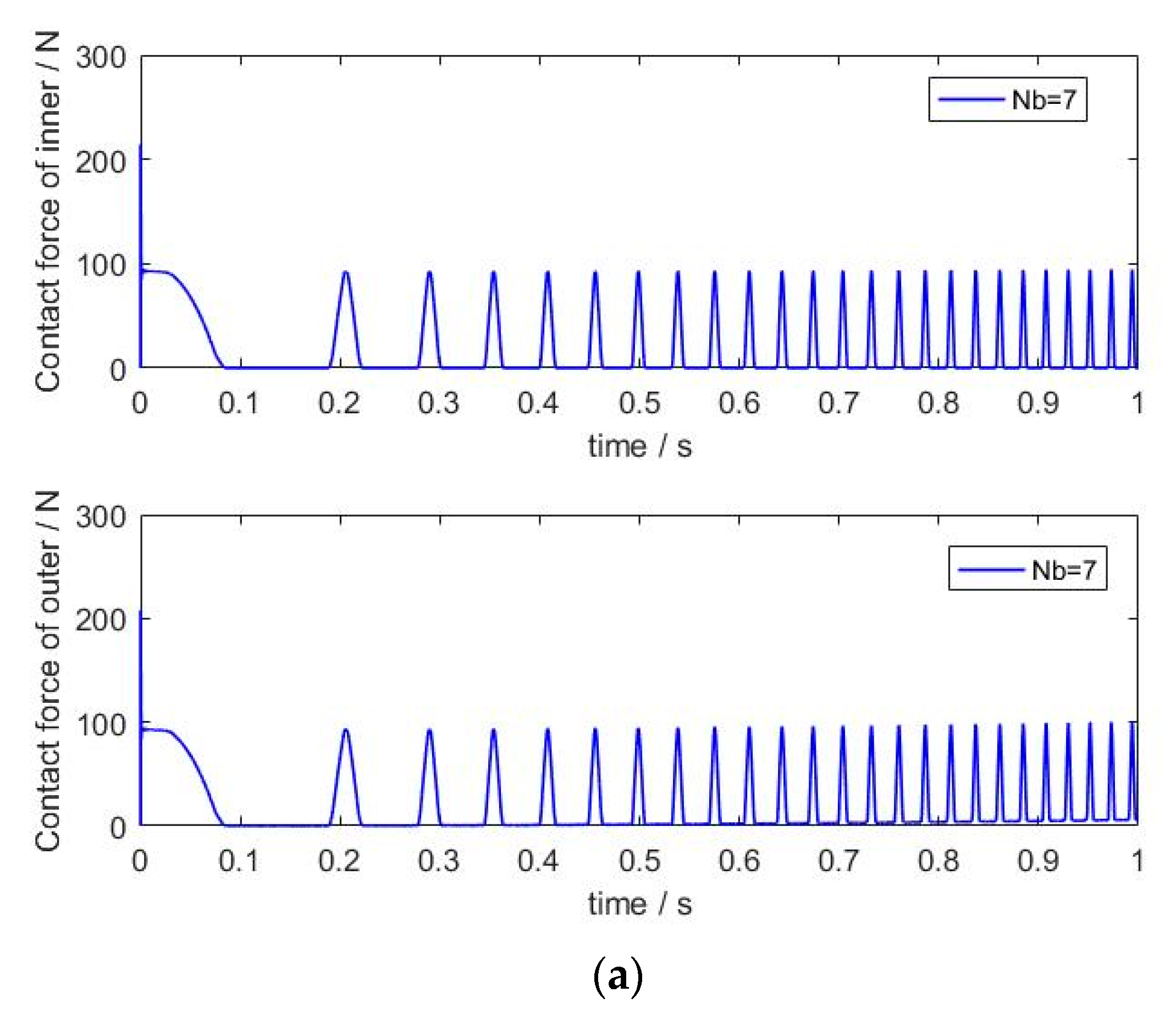
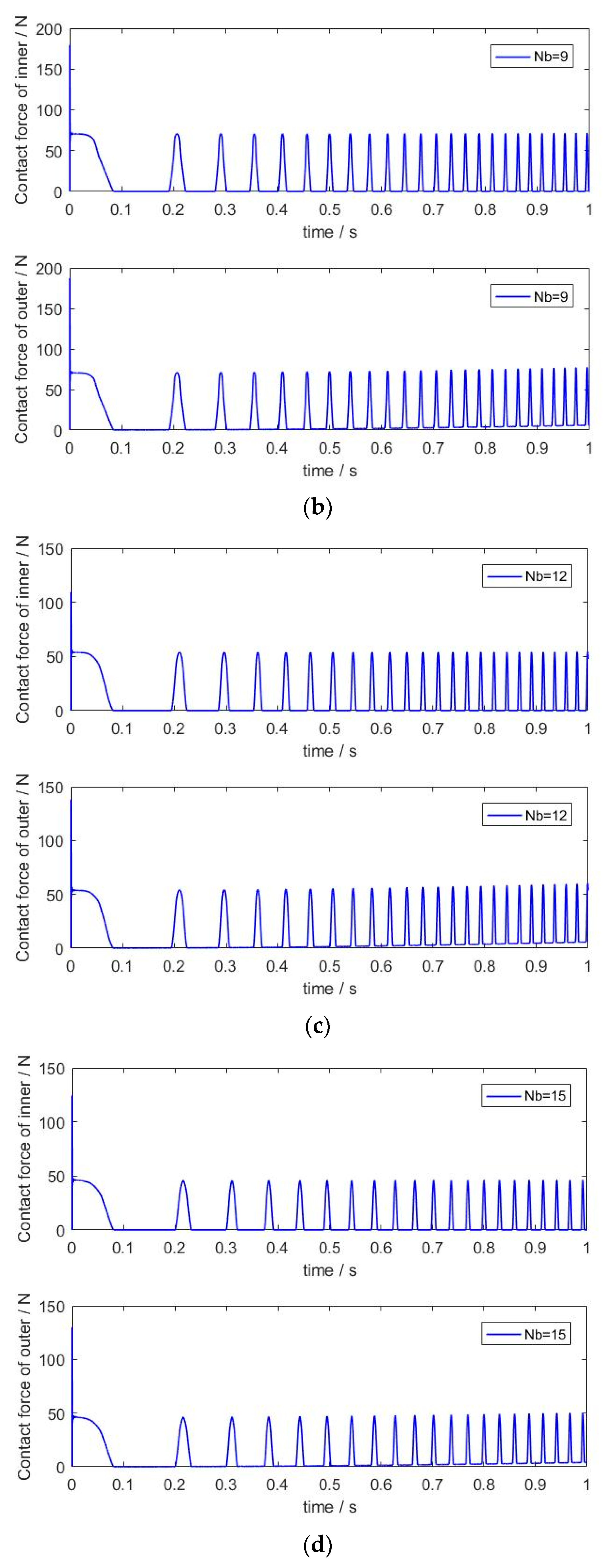
Figure 15, the friction force can reflect the contact characteristics in a tangential direction, and the change in friction force has a stronger connection with the velocity of a rolling ball. However, the variation in clearance size would change the peak value of the friction force and a bigger clearance size would enlarge the movement region of a rolling ball, which would cause a stronger collision between the rolling ball and the raceway. Meanwhile, the friction phenomenon would change the energy type in the contact–impact process for the contact elements. As is well-known, the friction force opposes the motion of the contact element and the transmission of the energy may cause the phenomenon of energy dissipation. Then, the working efficiency of a deep groove ball bearing would evidently decline. Furthermore, the number of the rolling ball can determine the load distribution characteristics of a deep groove ball bearing (as shown in
Figure 16). In the simulation, the clearance size was 0.005 mm, and the number of the rolling ball varied. An increase in the rolling ball number would increase the supporting points of the rolling ball in the load region. Then, more contact points could relieve the compressive force of the rolling ball and decrease the deformation of the raceway. When the number of the rolling ball is higher than 12, the contact force retains a stable value, and more rolling balls cannot evidently decrease the supporting force, as shown in
Figure 16c,d. Instead, more rolling balls would increase the mass of the deep groove ball bearing. Then, the centrifugal force and moment of inertia would also be changed. The similar characteristics would appear in the friction force, and, for this reason, this phenomenon can be used to explain that the friction force is associated with the value of the contact force by the Coulomb friction law. Then, the structural parameters of the deep groove ball bearing should be considered.
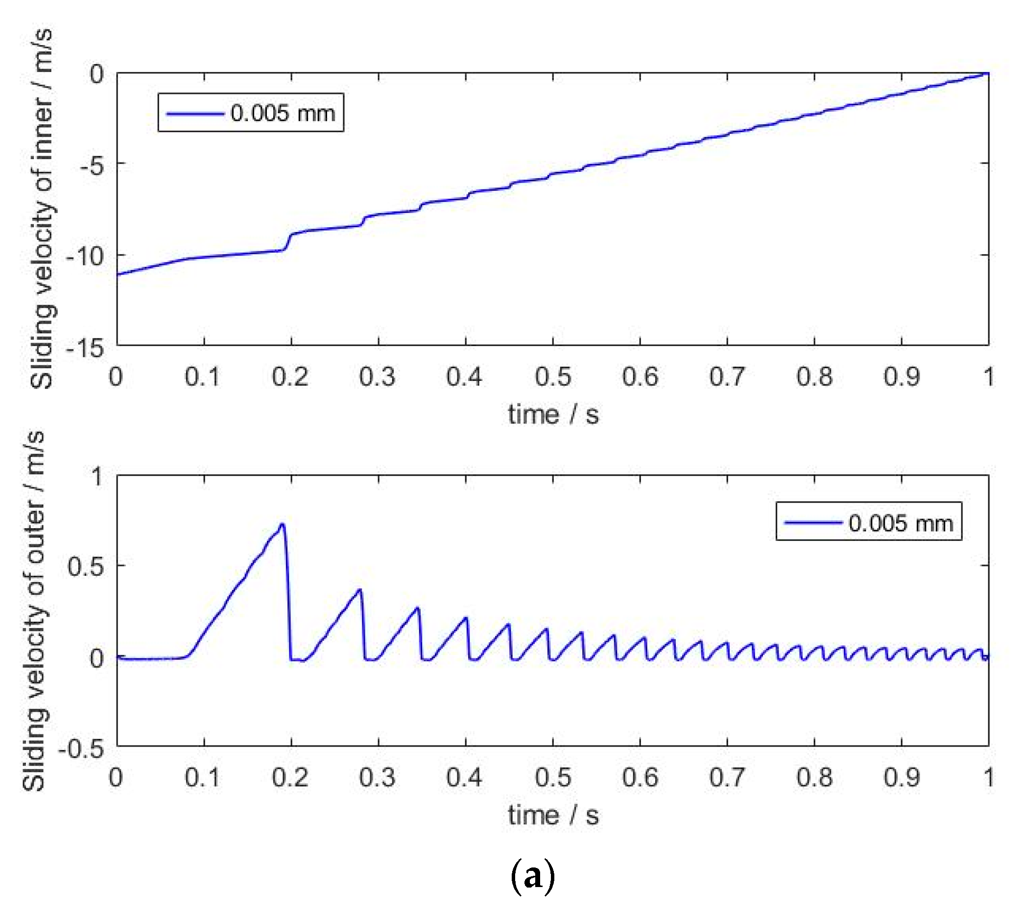
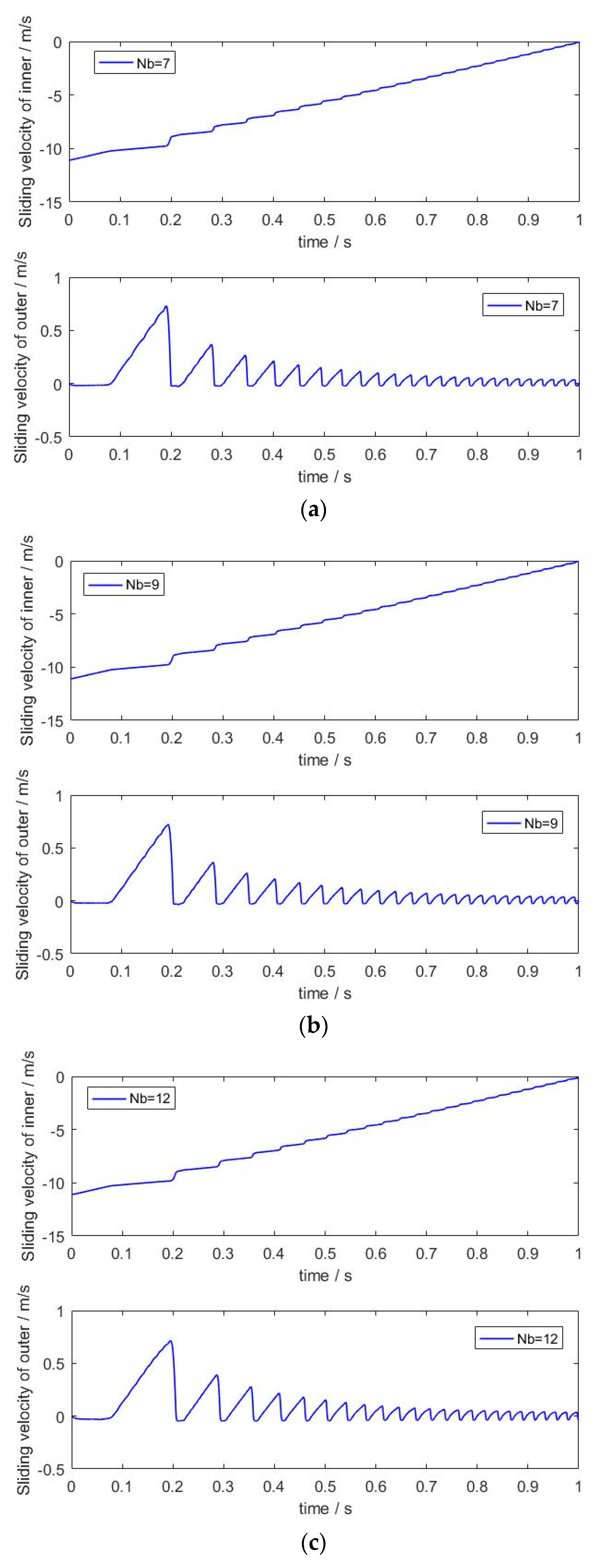
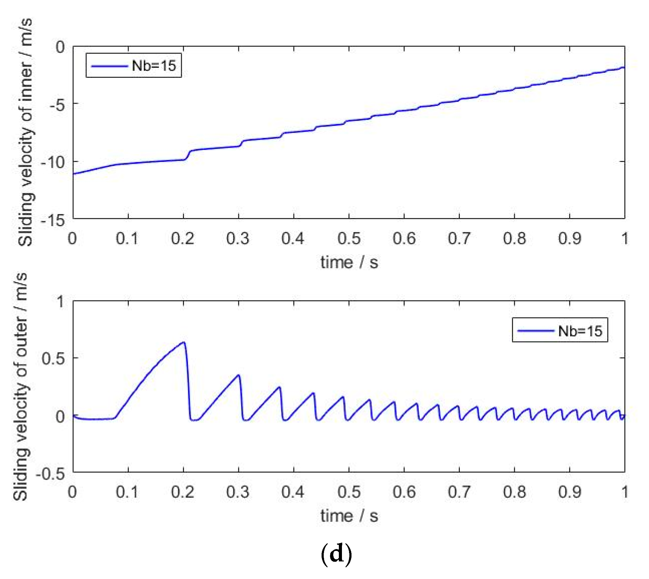
According to the results shown in
Figure 17 and
Figure 18, the sliding velocity between the rolling ball and the raceway changed as the structural parameters were varied. During the motion of the deep groove ball bearing, the sliding velocity was aligned with the rule of cyclical variation. However, the high-frequency fluctuation was produced in the load region. When the number of rolling balls was seven, these values increased evidently as the clearance size increased. When the clearance size exceeded 0.05 mm, the sliding velocity of the outer raceway vibrated, as shown in
Figure 17c,d. The clearance size is closely related to the movement region of a deep groove ball bearing, which is the main factor that affects the rotation speed of a rolling ball. A larger fluctuation is unfavorable for the stable motion of a deep groove ball bearing. Compared with the effects of clearance size,
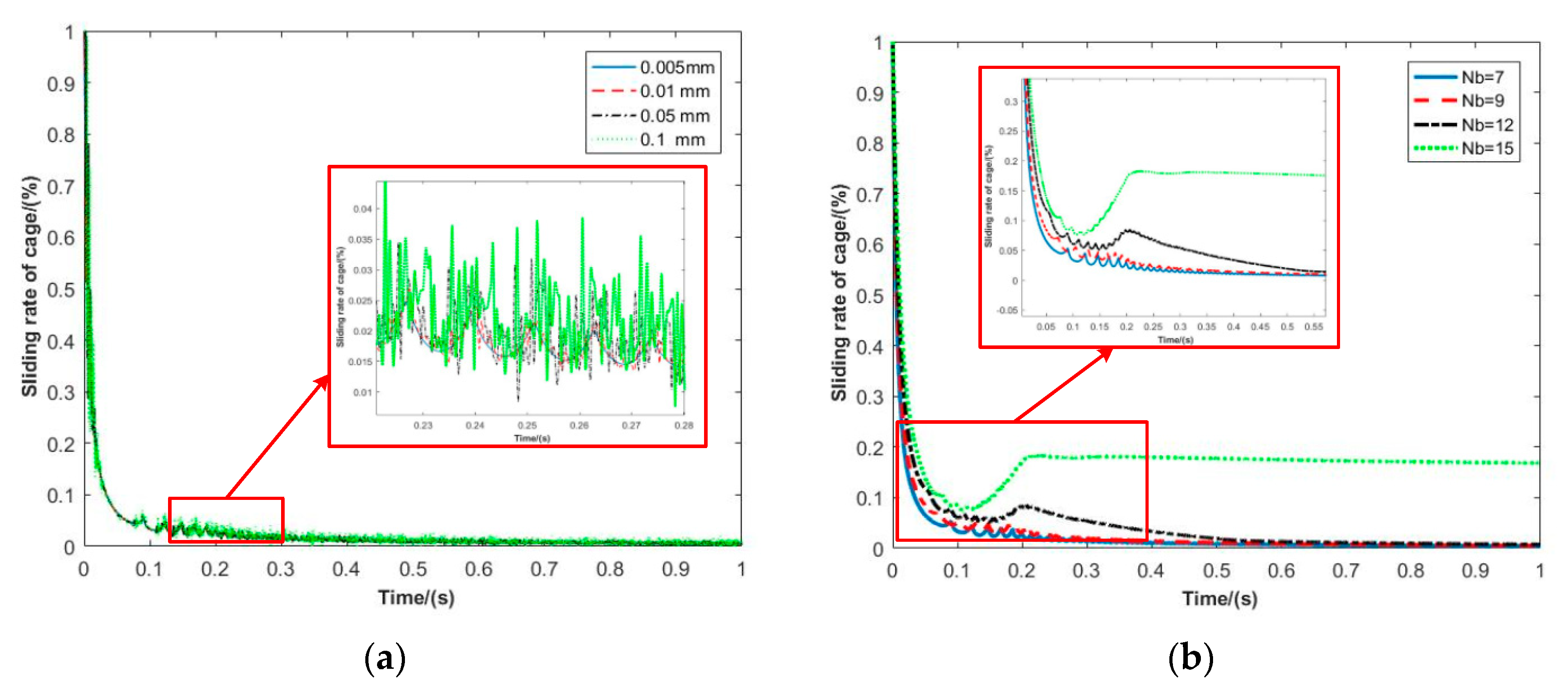
Figure 18 shows that the number of the rolling ball had little influence on the contact point (when the clearance size was 0.005 mm). The sliding velocity can be chosen for the dynamic characteristics of a rolling ball, and the slipping phenomenon may appear when there is a larger sliding velocity. Based on the results, the variation in the rolling ball number could change the stability of a deep groove ball bearing. In addition, the effects of the structural parameters on the sliding rate of the cage are evident, as shown in
Figure 19. A smaller clearance size is advantageous for shortening the time required to reach a stable value of the sliding rate for the cage. As seen in
Figure 19b, a smaller number of rolling balls provided repression of the rebound of the sliding rate, which may have improved the working efficiency of the deep groove ball bearing.
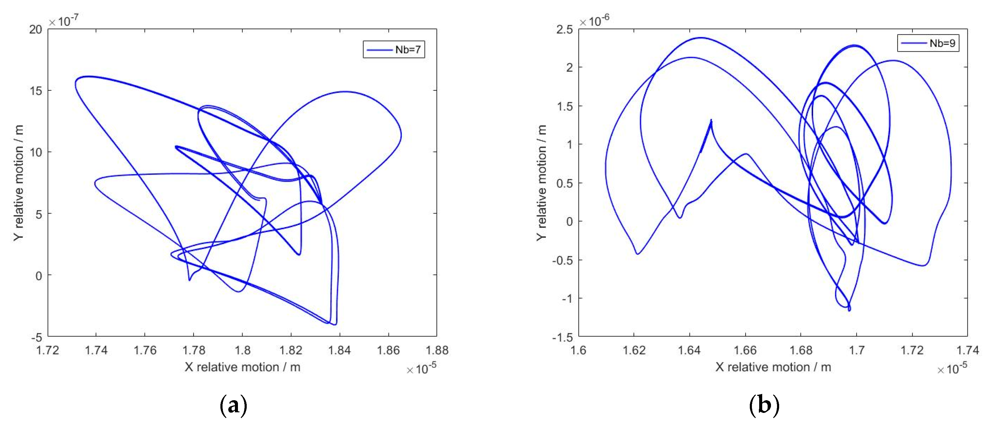
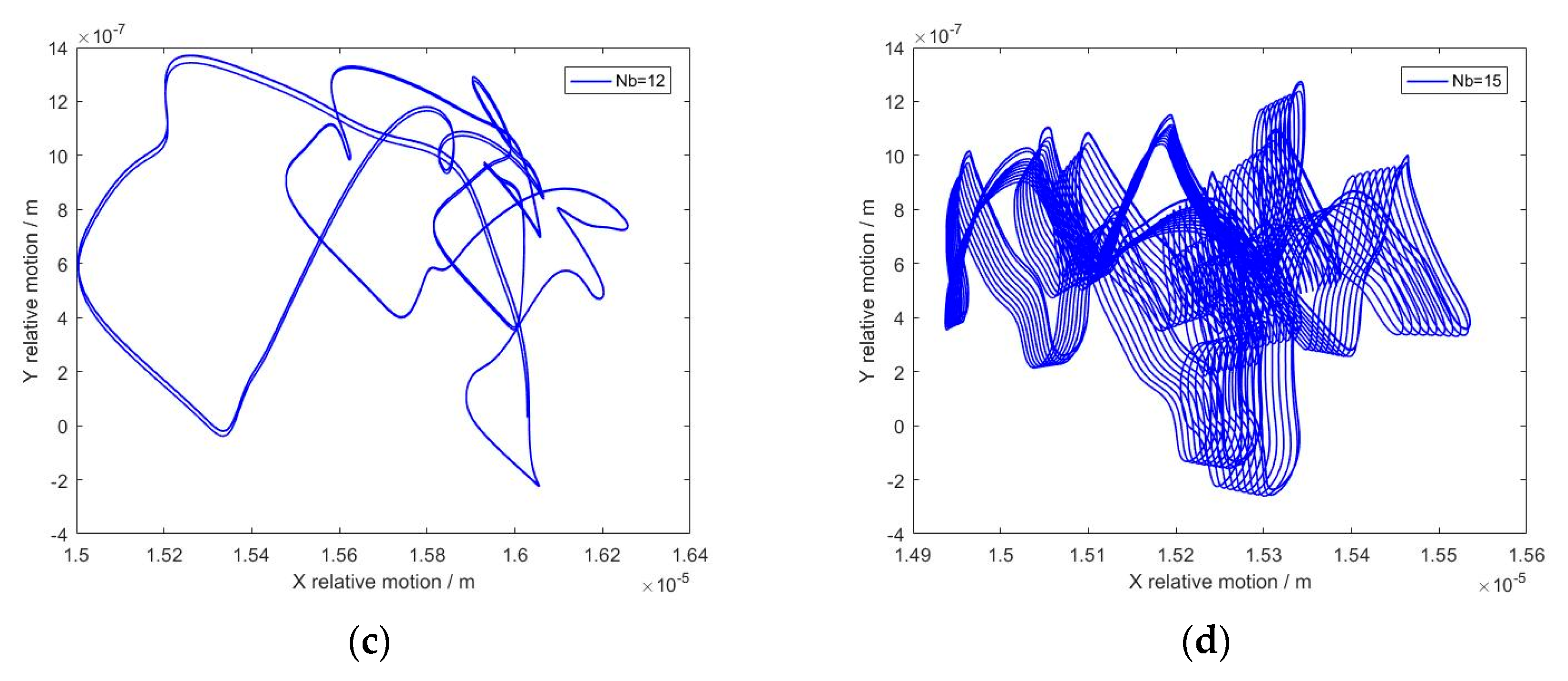
The center trajectory of the inner raceway has attracted attention in dynamic analyses of deep groove ball bearings, and it reflects the motion state of a rolling ball and an inner raceway. As shown in
Figure 20, the number of rolling balls was 7 and the clearance size was variable. The value of the clearance size was closely related to the path of the inner raceway center. The motion trajectory of the inner raceway contains the period characteristics, and the path of movement is clear. However, the motion state of the inner raceway can become the dispersion, and the quasi-periodic characteristics would be displayed. As the clearance size continues to increase, the center trajectory feature of the inner raceway changes evidently. Then, the reason for this phenomenon can be illustrated such that the increase in clearance size enlarges the motion region of the ball. The related motion between the rolling ball and the inner raceway is no longer stable and predictable. Although the increase in rolling ball number could provide more supporting points for the inner raceway, the increase in collision frequency would cause an unstable motion trajectory for the inner raceway, as represented in
Figure 21. In this case, the clearance size was defined as 0.005 mm and the number of rolling balls increased from 7 to 15. It was noteworthy that the growth in rolling ball number could cause variations in the contact frequency and the contact point of the raceway, which may lead to the appearance of a complicated movement path. Greater rolling ball numbers improve the complexity of multibody systems for deep groove ball bearings, and the motion elements also increase. The variation in contact frequency changes the position, value, and deformation of the contact elements, which is directly related to the center trajectory of the inner raceway. Therefore, an analysis of the motion trajectory should be conducted during the design of deep groove ball bearings.
Based on the results, the increase in clearance would cause a visible fluctuation of movement for deep groove ball bearings. Especially in an acceleration state, variations in the structural parameters have evident effects on the contact characteristics and sliding features. The rebound phenomenon of the sliding rate for the cage is closely related to the number of the rolling ball. In addition, the periodicity of the center trajectory for the inner raceway is determined by the structural parameters, which should be considered during the design of deep groove ball bearings.


