Article

Predicting and Reinforcing the Critical Buckling Loads of Flexible Corrugated Panels

1
College of Aerospace Engineering, Nanjing University of Aeronautics and Astronautics, Nanjing 210016, China
2
School of Aeronautic Science and Engineering, Beihang University, Beijing 100190, China
3
Faculty of Science and Engineering, Swansea University, Swansea SA1 8EN, UK
*
Author to whom correspondence should be addressed.
Machines 2023, 11(3), 339; https://doi.org/10.3390/machines11030339
Submission received: 27 January 2023 / Revised: 24 February 2023 / Accepted: 28 February 2023 / Published: 1 March 2023
(This article belongs to the Special Issue Dynamic Stability Analysis of Aerospace Structures)

Abstract

:
Corrugated panels are promising in the field of morphing structures due to their high anisotropy. A low stiffness in the morphing direction allows for a reduced actuation force, which provides the benefit of reducing the system weight. However, a low stiffness also leads to reduced critical buckling loads, which makes it easier for corrugated panels to buckle in the morphing process. The conflict between the actuation force and the critical buckling load requires an efficient method to predict the critical buckling load, which can then be applied in a trade-off study to find the optimal design. In the current study, a simplified method to predict the critical buckling load is proposed based on the derivation of equivalent properties. The method is verified using the finite element analysis and applied for the optimisation of corrugated panels. A conceptual design to reinforce corrugated panels is also proposed, which shows a significant increase in the critical buckling load of flexible corrugated panels.

1. Introduction

Corrugated panels have been widely used in civil engineering, package engineering and aerospace engineering. The highly anisotropic mechanical properties of corrugated panels have also aroused extensive research interests for the application of morphing structures.
In morphing structures, corrugated panels are used as flexible structures, which can deform sufficiently without failure when subject to actuation loads but also provide a reasonable stiffness to withstand aerodynamic loads. Corrugated panels have been applied in morphing wingtips [1,2], camber morphing wings [3,4] and wind turbine blades [5,6].
The application in morphing structures has made the modelling of the equivalent properties of corrugated panels vital [7]. Ghabezi derived stiffness matrices for composite corrugated skins with rectangular and triangular corrugations and found that corrugated panels could undertake larger deformations than flat panels, making them promising in the field of morphing aircraft [8]. Quasi-sinusoidal corrugated panels were also investigated by Ghabezi and Golzar [9], and they also showed a high stiffness in the load-carrying direction and a low stiffness in the morphing direction. An equivalent model using the homogeneous method was built by Xia et al. [10] to predict the stiffness of corrugated panels. This method was based on the classical plate theory and is applicable for general corrugation shapes. A modification considering the influence of boundary conditions was proposed in [11] by Wang et al., and it was used to create an equivalent beam model for the optimisation of morphing winglets [2]. To provide a smooth aerodynamic surface, corrugated panels with flexible coatings were also investigated by Dayyani [12]. The nonlinear mechanical response of corrugated panels was investigated by Bai et al. [13] using a semi-analytical approach and by Kress and Filipovic [14] using a simplified analytical method. In addition to the stiffness properties, the deformation limit of corrugated panels also determines whether they can be used in morphing structures. The deformation limits of corrugated panels with two circular segments were found by Winkler and Kress [15], and the bending limits of corrugated panels were found by Schmitz and Horst [16]. The homogeneous method proposed by Xia et al. [10] was extended to predict the global strain limits of corrugated panels [17] by linking the local strain of the material to the global strain of the entire panel.
The research of the different modelling methods has accelerated the development of flexible corrugated panels. However, one of the drawbacks of using flexible corrugated panels as morphing structures is the reduced stability, especially when they are subject to compression loads. For morphing applications, it is necessary to estimate the critical buckling loads and to find a way to increase the buckling stability of corrugated panels subject to actuation loads while keeping the corrugated panels flexible for morphing.
Shaw, Dayyani and Friswell [18] investigated the local and global buckling modes of corrugated panels and optimised the corrugation shape for the minimum weight. However, few studies have been performed to estimate the critical buckling loads in the flexible direction and to find proper methods to reinforce them in that direction. Jamming is a physical phenomenon, in which the material transforms from a liquid-like state to a solid-like state. The concept of granular jamming has been applied in the field of soft robotics as an actuation method [19,20,21], in which active pressure control is used to tune the stiffness of jamming materials. However, Li, Chen and Li used the so-called passive jamming concept to stiffen soft robots [22], in which the jamming material was filled into the robots, and the frictions between the material was used to stiffen them. Since no pressure is required to tune the stiffness, the concept is called ‘passive jamming’ and shows the potential to reinforce flexible structures without an active control system.
In the current research, the critical buckling loads of corrugated panels in the flexible direction are calculated using an equivalent model, and the analytical results are verified using a numerical analysis. A trade-off study is then applied to find a balance between the critical buckling load and the tension stiffness of the corrugated panels. The current study also tries to reinforce corrugated panels by increasing their critical buckling loads using the so-called passive jamming concept. A case study is applied to highlight the effect of passive jamming and to validate the proposed concept.

2. Critical Buckling Load Prediction

2.1. Equivalent Model

Figure 1 shows a corrugated panel, which has periodic shapes along its neutral axis. The round corrugation shape is adopted in the current study, although the method can be applied more generally. The corrugated panel has a low stiffness along the x direction, which is defined as the morphing direction in this paper. The length of the corrugation, the radius of the circle and the corrugation units are denoted as L, R and n, respectively. The cross-section area, the width and the thickness of the panel are denoted as A, b and t, respectively.
The equivalent model is obtained by deriving the overall deflections of the corrugated panel when it is subject to different load cases. Although the round corrugation shown in Figure 1 is investigated in the current study, the proposed method can be applied in a more general way if the equivalent properties of the corrugated panel are obtained.
The detailed derivation of the equivalent properties can be found in [23]. The equivalent properties of the corrugated panel are expressed as
E I ¯ = 2 R E I π R + 2 L E A ¯ = 12 R E I 4 L 3 + 6 π R L 2 + 24 R 2 L + 3 π R 3
where E I ¯ and E A ¯ are the equivalent properties corresponding to the bending and tension stiffnesses. E and I represent the Young’s modulus of the material and the second moment of the area, respectively.
For a classical beam, the critical buckling loads can be obtained using the Euler column formula:
F c = π 2 E I ( μ l ) 2
where μ is the factor of the end conditions, and l is the length of the beam.
The formula assumes that the beam follows the classical theory and has homogeneous and isotropic properties. To obtain the critical buckling load of the corrugated panel effectively, the equivalent bending properties E I ¯ from Equation (1) are applied in Equation (2) as
F ¯ c = π 2 E I ¯ μ l 2
For the round corrugation shape adopted in this study, we have
F ¯ c = π 2 E I ¯ μ l 2 = π 2 μ l 2 2 R E I π R + 2 L = π 2 μ l 2 2 R b t 3 12 π R + 2 L
The overall length of the corrugated panels l is calculated as
l = n 4 R
The factor of the end condition μ = 2 due to the fixed boundary condition in the current study.

2.2. Numerical Verification and Parametric Study

To verify the above method, the finite element method is applied to estimate the critical buckling loads of corrugated panels. The commercial finite element software Abaqus® is used, and the critical buckling loads are calculated using the eigenvalue buckling prediction method [24]. The S4R shell elements are used to build the model, as shown in Figure 2. The S4R element is a general-purpose shell element that can predict the mechanical properties of both thin and thick shells. The mesh size is 1 mm to ensure the meshing quality. One end of the corrugated panel is fixed, and the compression loads are applied to the other end. The critical buckling loads are obtained by timing the first mode eigenvalue to the compression loads applied to the corrugated panel.
A parametric study is performed to compare the critical buckling loads obtained using the analytical method and the numerical method. Ten corrugation units are used in the finite element models, and the width of the panels remains 10 mm for the convenience of comparisons. Figure 3 and Figure 4 show the results of the parametric study. The Young’s modulus E of the material is 72 GPa, and the Poisson’s ratio is 0.3 in the current study.
Figure 3 shows the critical buckling loads with variations in the corrugation unit length L, the radius R and the panel thickness t. The ranges of the variables L and R are chosen to ensure that the minimum length and radius of the corrugation unit are 5 times greater than the panel thickness.
The analytical results are very close to those obtained from the finite element analysis. The relative error between the analytical and numerical simulations is below 2%, which verifies the accuracy of the equivalent model. The results also indicate that, as the corrugation unit becomes larger, the critical buckling loads will reduce, which is due to the reduced equivalent bending stiffness of the corrugated panel according to Equation (1). Increasing the panel thickness will lead to a higher critical buckling load since the stiffness of the panel is increased with the thickness.
In addition to the parametric study of the corrugation unit, the overall size of the corrugated panel is also investigated. Figure 4a shows the effect of the number of corrugation units n and the panel width b. According to Equation (3), the corrugated panel will buckle more easily when the overall length of the corrugated panel becomes longer. The analytical and numerical analyses are used to predict the trend, and the results agree with each other very well.
An increase in the panel width will lead to a linear increase in the critical buckling load according to Equation (3). Figure 4b predicts the trend successfully and estimates the buckling loads accurately.
Hence, the proposed equivalent model can estimate the critical buckling loads accurately according to the results’ comparisons. It should be noted that both the analytical and finite element analyses only take the first buckling mode into account when the corrugated panel is under compression.

3. Trade-Off Study

As morphing structures, corrugated panels need to be flexible enough when they are subject to actuation loads. Thus, in addition to the critical buckling loads, the tension stiffness of the corrugated panel along the direction of the actuation force is also chosen as the performance index to evaluate the mechanical properties of the corrugated panels.
To eliminate the effects of the size and the material, the indexes are nondimensionalised by dividing them with those of flat panels with the same overall size, cross-section shape and material properties.
Thus, the indexes are denoted as
ϕ = F ¯ c F c = 2 R π R + 2 L κ = E A ¯ E A = R 4 L 3 + 6 π R L 2 + 24 R 2 L + 3 π R 3 t 2
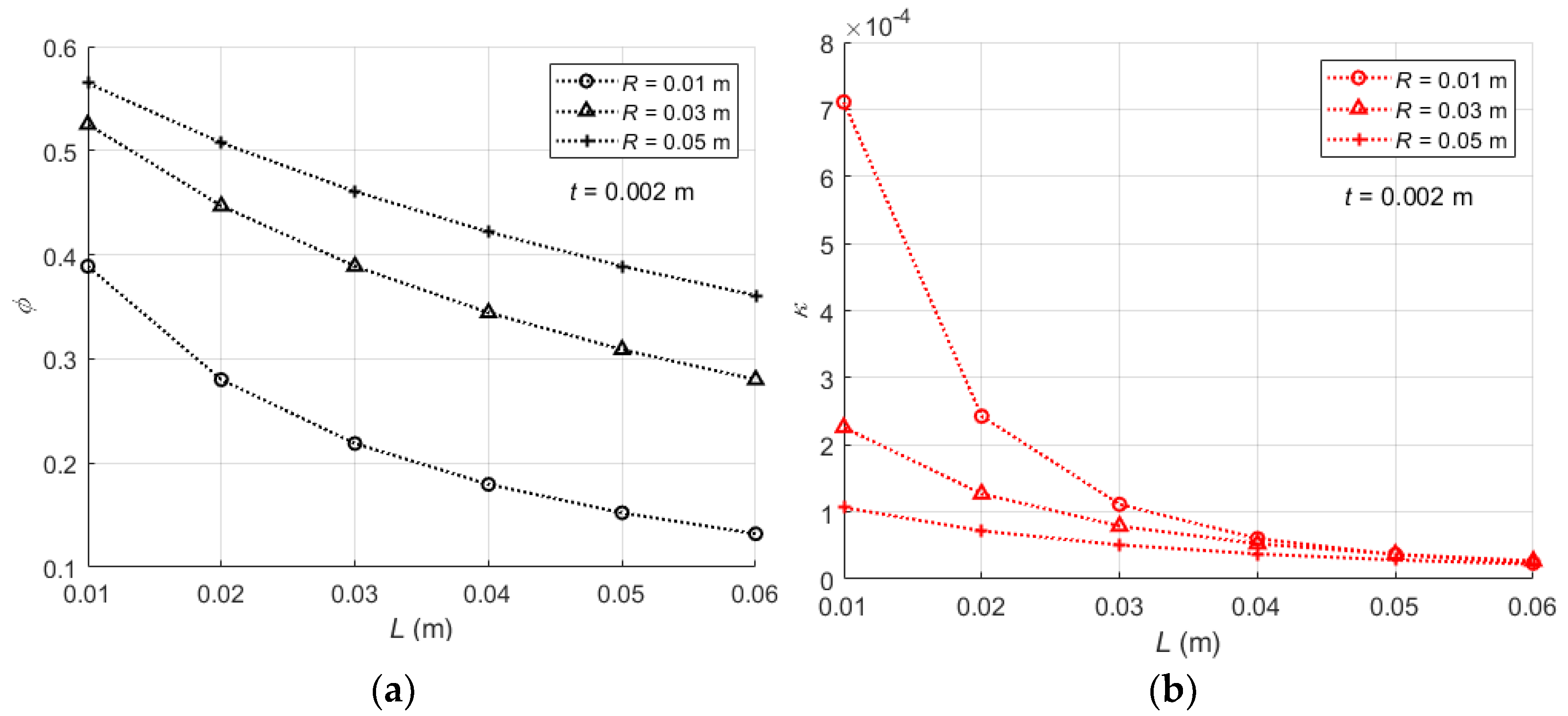
Here, ϕ is the nondimensional critical buckling load, and κ is the nondimensional tension stiffness.
Clearly, the nondimensional indexes are not affected by the overall size or the material properties, and they only vary with the corrugation unit geometry. Figure 5 shows the effect of the corrugation shape parameters. When the corrugation geometry parameters L and R increase, both indexes reduce. Moreover, the nondimensional tension stiffness is found to be much smaller than the nondimensional critical buckling load for the same geometry parameters, which indicates that, in the morphing direction, the flexible corrugated panel is very flexible, while a moderate buckling load can still exist.
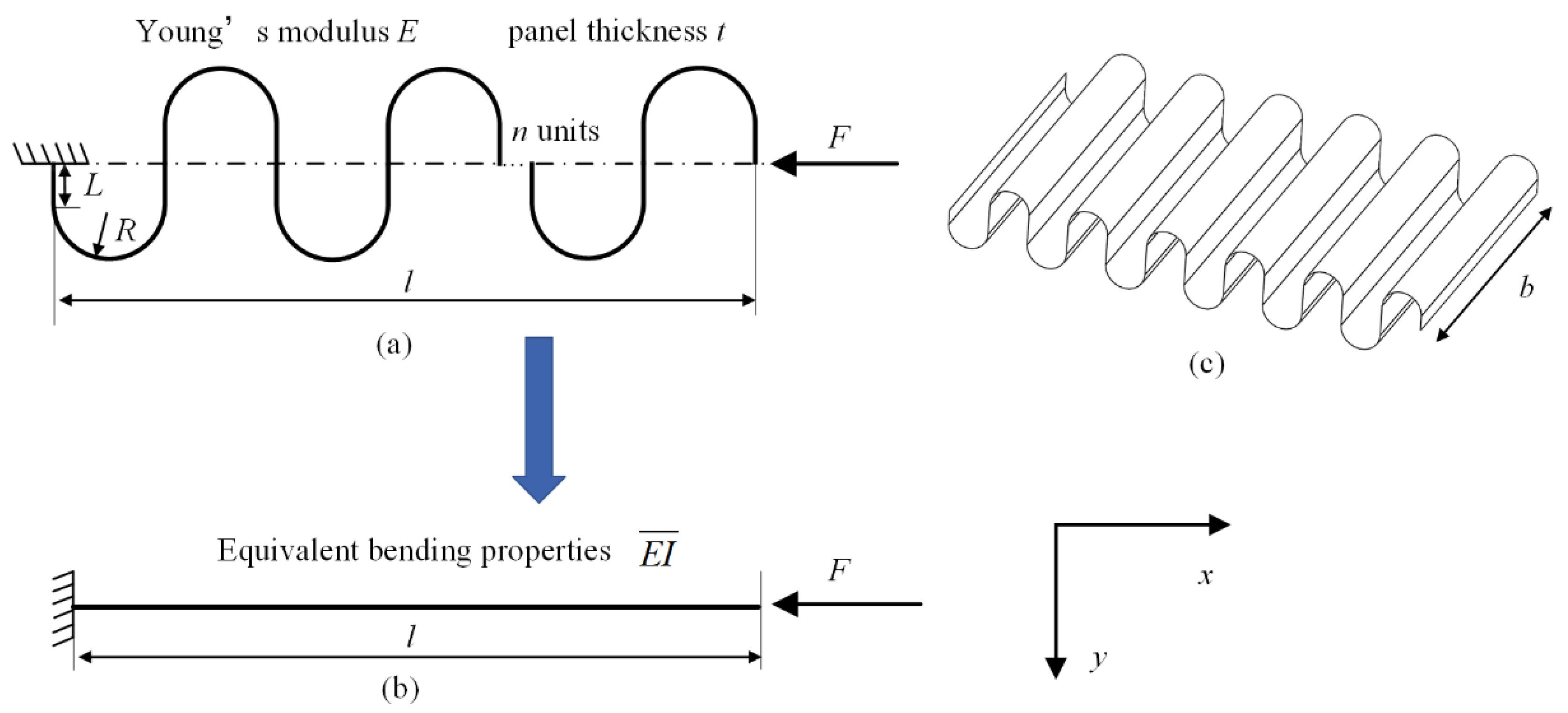
For a flexible corrugated panel, it is expected that the actuation force is limited when it is under extension and that buckling does not occur when it is under compression. Thus, a low-tension stiffness and a high critical buckling load are expected in the x direction, as shown in Figure 1. However, 
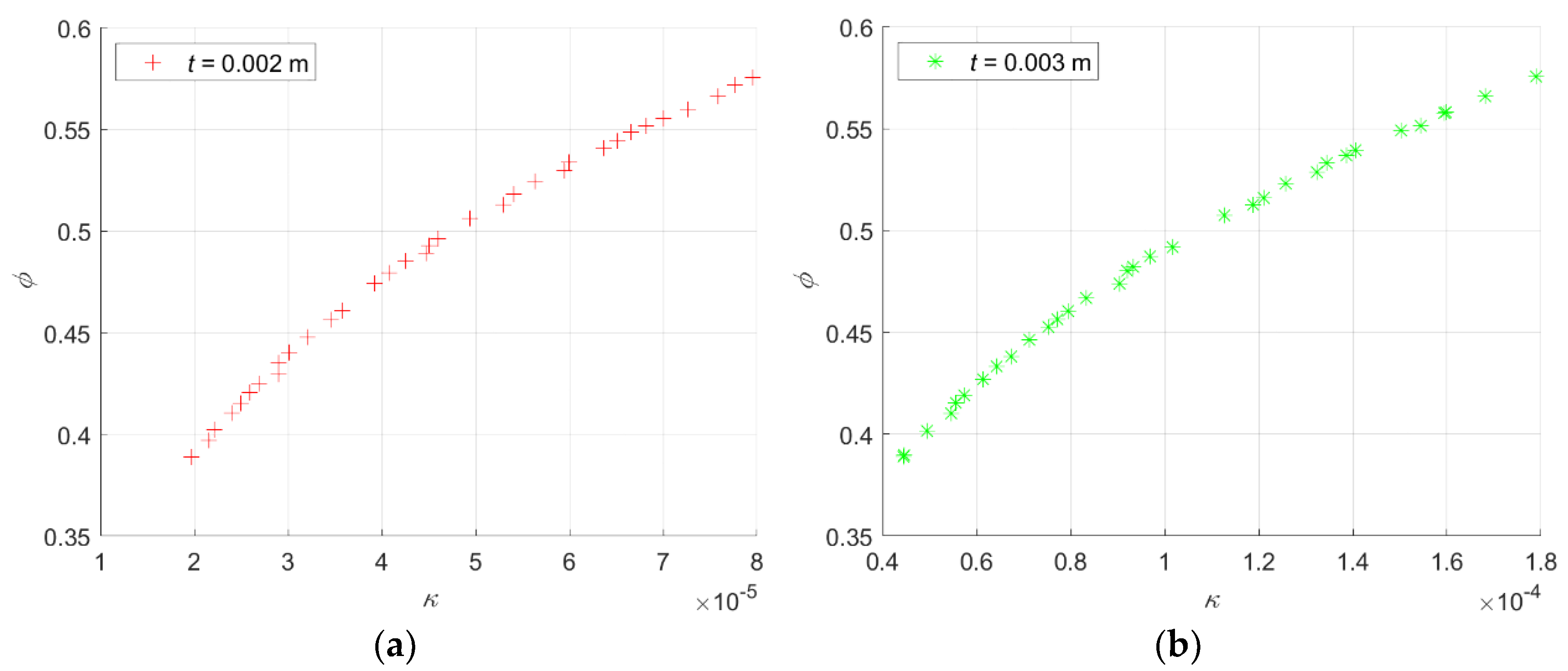
Figure 5 shows that the indexes have a similar trend when the corrugation geometry parameters change. A trade-off study is required to determine the optimal geometry parameters that can satisfy the requirements of low actuation forces and high critical buckling loads simultaneously. The Pareto front is usually applied to show the relationship between the two indexes, and the optimal variables can be determined according to the specific load cases.
A two-objective optimisation is performed to find the objectives as follows:
min κ max ϕ
The corrugation geometry parameters L and R are chosen as design variables, while the thickness remains fixed since it only affects κ.
0 . 01 L 0 . 06   m 0 . 01 R 0 . 06   m
The genetic algorithm is applied to find the Pareto front of the objectives. The population size, max generation and crossover fraction are set to 200, 1000 and 0.6, respectively. As shown in Figure 6, when the nondimensional tension stiffness is reduced, the nondimensional buckling loads also reduce and vice versa. The panel thickness only affects the stiffness and does not change the optimal buckling loads. Due to the conflict between the two indexes, the optimal solution for a morphing design will be determined if the specific requirements of the indexes are given.

4. Reinforcement Using Passive Jamming

4.1. Conceptual Design

The results in Section 2 and Section 3 show that it is much easier for the flexible corrugated panel to become unstable due to reduced critical buckling loads in the x direction. Although buckling can be delayed by tuning the geometry parameters of the corrugation units, the critical buckling load of a corrugated panel is inherently lower than that of a flat panel. Therefore, a conceptual design to reinforce a flexible corrugated panel is proposed, which aims to increase its critical buckling load but keep the tension stiffness low in the morphing direction.
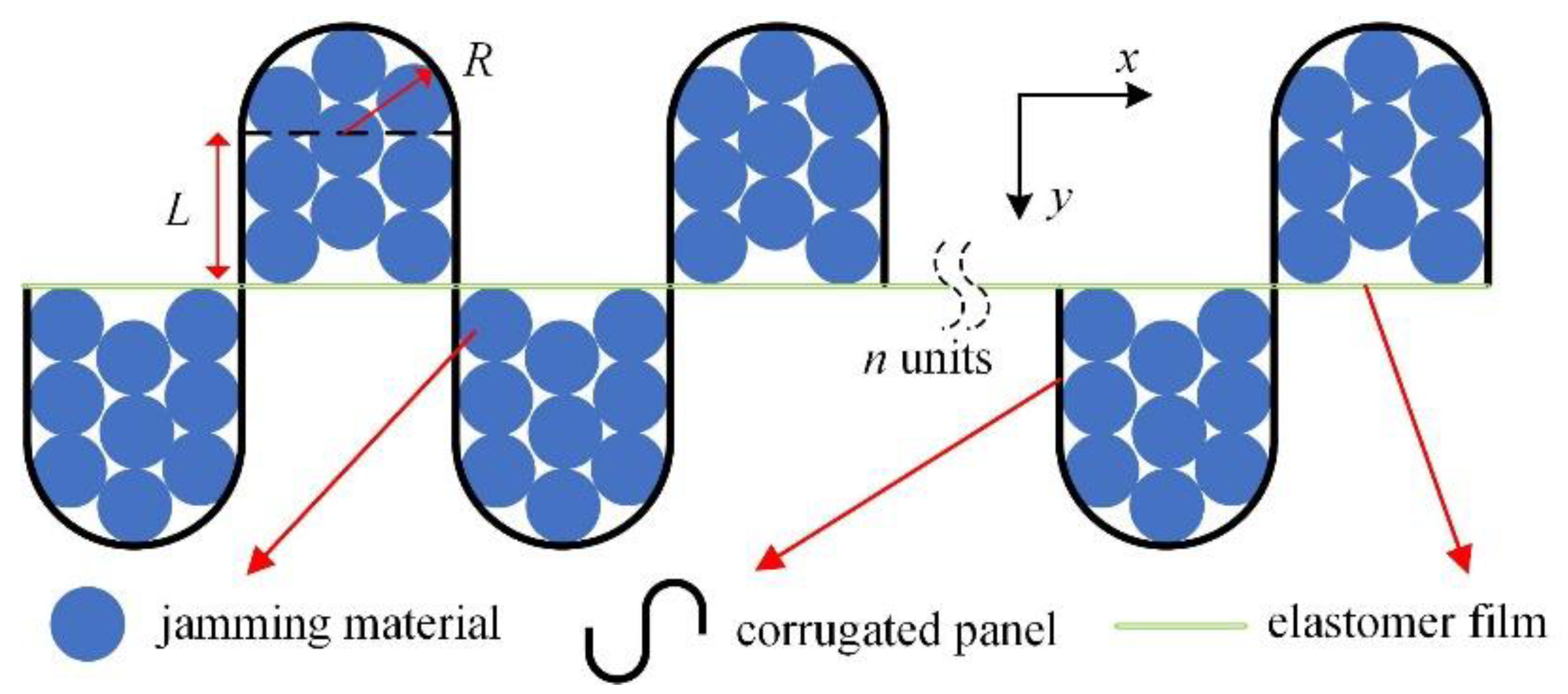
As shown in Figure 7, the corrugated panel is filled with a jamming material, and an elastomer film is used to seal the units. In the current research, circular tubes, such as carbon fibre tubes, are used as the jamming material, and granular seeds, such as coffee beans, can be adopted in a more general situation in the future. It is noted that Figure 7 only shows the concept of a reinforced corrugated panel and does not show the real positions or number of jamming materials.
When no external loads are applied, the jamming materials have loose contact with the corrugated panel, the elastomer film and themselves.
Obviously, if the reinforced corrugated panel is under tension along the x direction, the jamming material will not interfere with the deformation of the corrugated panel. The overall tension stiffness of the reinforced panel is determined by the stiffness of the corrugated panel and the stiffness of the elastomer film. Since the elastomer film is very flexible, only a moderate increase in the tension stiffness can be expected. Moreover, gravity is not considered in the current study.
However, if the reinforced corrugated panel is under compression along the x direction, the jamming material will gradually form close contact, which will lead to friction between the jamming material and a higher overall resistance to compression. The compression stiffness can then be increased, which corresponds to an increased critical buckling load.

4.2. Conceptual-Level Validation

To validate the concept, the critical buckling loads of the reinforced corrugated panel are obtained using the finite element analysis, and a case study is applied to demonstrate the concept. The corrugated panel has the geometry parameters of L = 0.02 m, R = 0.015 m, t = 0.003 m, b = 0.01 m and n = 5. As a conceptual-level study, the jamming material is modelled as a homogeneous material, and the interactions between the jamming material and the corrugated panel are neglected in the current study. The entire inner area of the corrugated panel is assumed to be filled by the jamming material, and the effect of the volume fractions of the jamming material will be investigated in a future study.
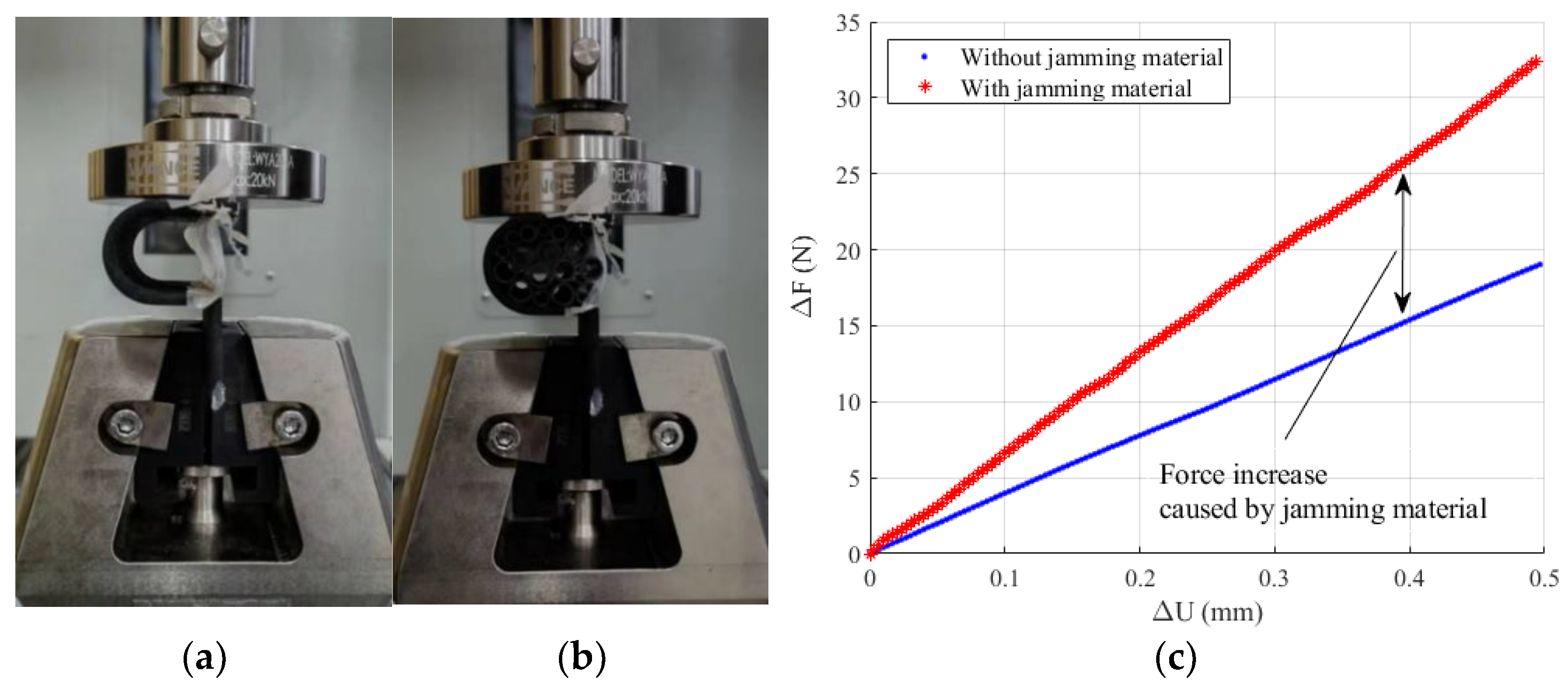
The Young’s modulus of the jamming material is obtained from compression tests. The compression tests are shown in Figure 8, and they are performed in the universal test machine WANCE® TES 105D. The maximum measurement range of the load cell is 200 N, with the measurement accuracy level at 0.2%. A half corrugation unit is fabricated using a 3D printer, and silicone rubber is applied to seal the corrugation unit. Considering the manufacturing conditions, the Young’s modulus of the 3D printed material will not be exactly the same as that in its product manual. Thus, in the current study, the compression tests are not applied to obtain the critical buckling loads but rather to determine the stiffness increase due to the filled jamming material. Since the filled jamming material is treated as a homogeneous material, its equivalent Young’s modulus can be obtained once the stiffness increase due to the filled material is determined. The stiffness increase is observed as shown in Figure 8c, which inherently represents the hardening effect of the jamming material.
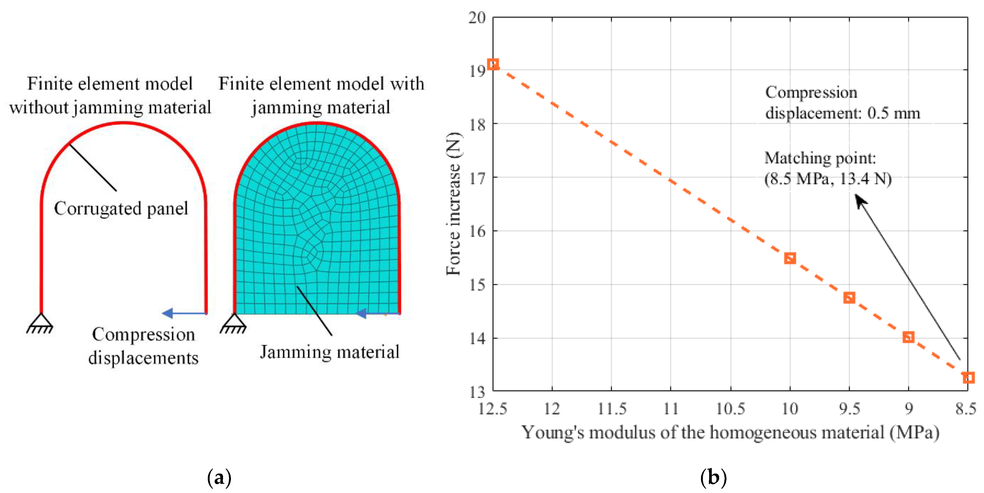
Then, a finite element model of the corrugation unit is built, as shown in Figure 9a. The jamming material is modelled as a homogenous material using the solid element C3D8R, and the corrugated panel is modelled using the shell element S4R. Only a half corrugation unit is applied to obtain the Young’s modulus of the jamming material. Compression displacements are applied to the corrugation unit, and the reaction forces at the boundary conditions are obtained as the compression force.
The Young’s modulus of the homogeneous material can be found inversely by matching the force increase observed in the numerical results to that observed in the experimental results. In the case study, the compression displacement is 0.5 mm, and the modulus of the jamming material in the finite element model is varied linearly until the force increase in the finite element analysis can match that in the compression tests. By trial and error, the equivalent Young’s modulus of the jamming material is finally taken as 8.5 MPa in the current study, as shown in Figure 9b.
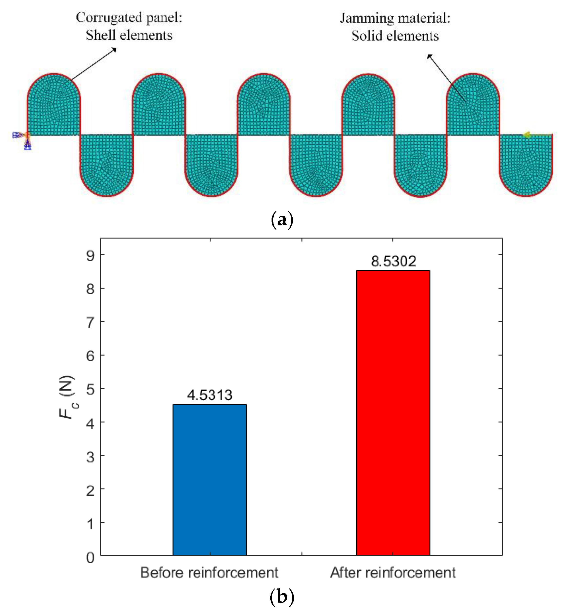
A finite element model of the reinforced corrugated panel is then estimated as shown in Figure 10a. All the other settings are the same as those without the jamming material in Section 2, except that the jamming material is modelled with a Young’s modulus of 8.5 MPa. The critical buckling loads are obtained in Abaqus® using the eigenvalue prediction method. The effect of the reinforcement is highlighted in Figure 10b. The critical buckling load is increased by 88% from 4.53 N to 8.53 N, which represents a significant improvement for the flexible corrugated panel.

5. Conclusions

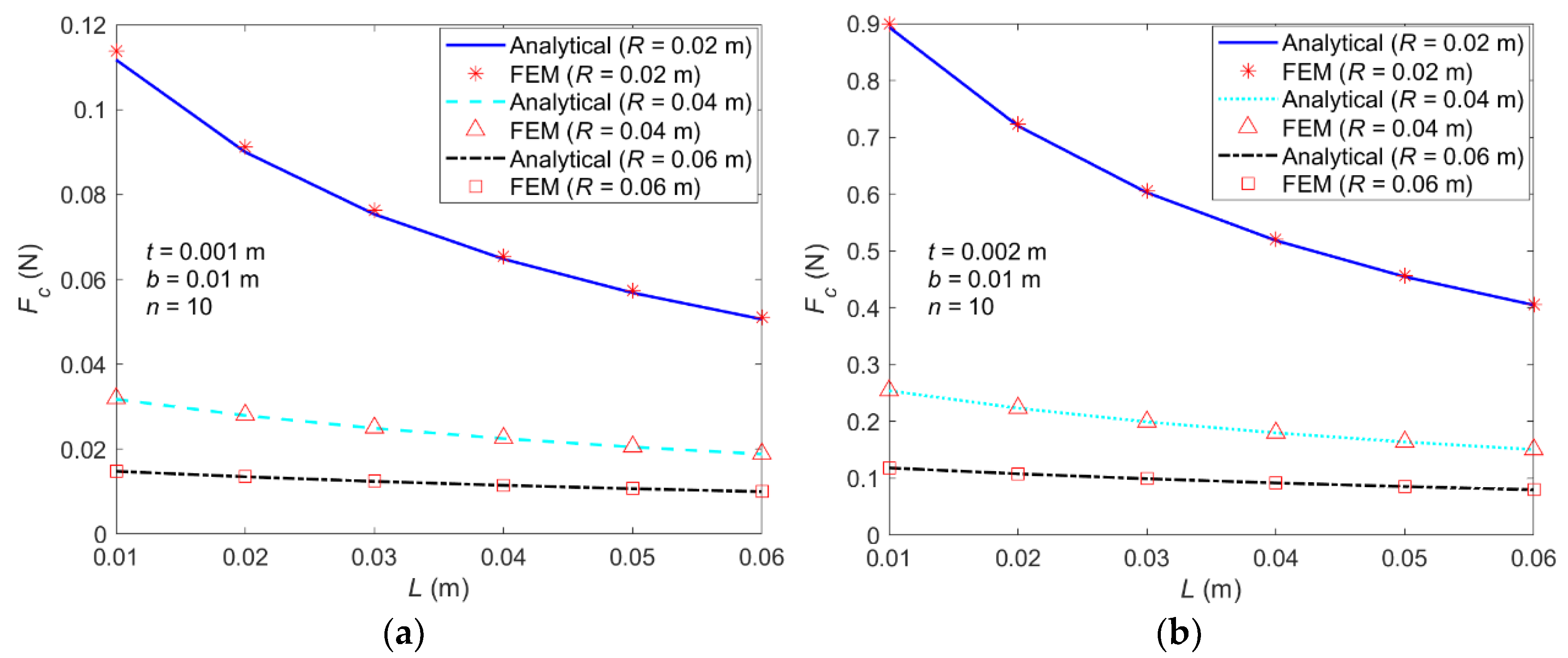
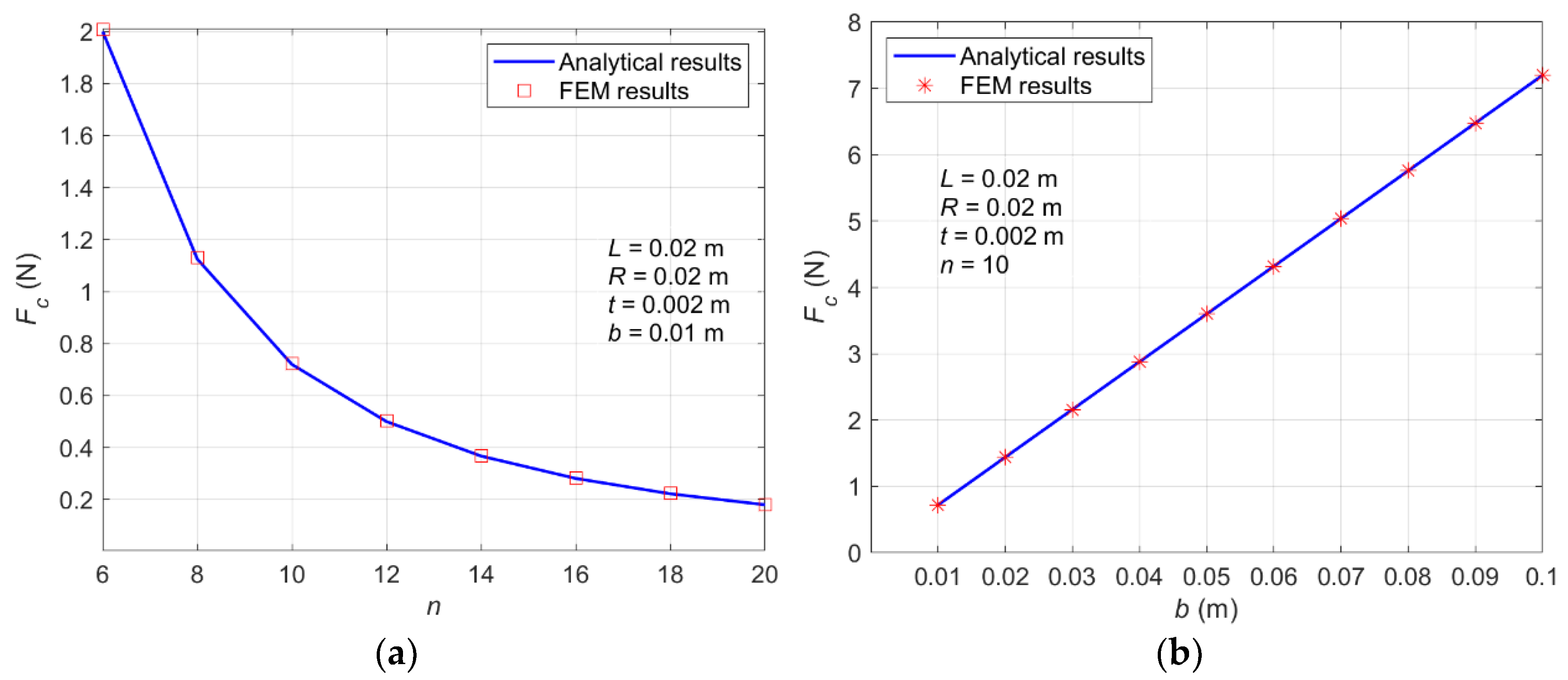
In this paper, a simplified method is preliminarily proposed to predict the critical buckling loads of flexible corrugated panels, and the equivalent properties of the corrugated panels are applied. Analytical solutions are derived, which are then verified using the finite element analysis. Parametric studies are applied to determine the effects of the corrugation geometry and overall size.
A trade-off study is performed to obtain the Pareto front of the critical buckling loads and the tension stiffnesses. It shows that improving the critical buckling load just by changing the geometry parameters usually comes with an increase in the tension stiffness, which could cause a penalty in the increased actuation force.
A novel method to reinforce corrugated panels while keeping the tension stiffness low is proposed by filling the jamming material into the corrugation units, which can passively lead to an increase in the compression stiffness but only a moderate increase in the tension stiffness. A case study is performed to validate the concept schematically, which shows a significant improvement in the critical buckling load.
The current study mainly shows analytical and numerical results. Experimental work will be performed in a future study to further verify the proposed method and to extend the research from a conceptual-level study to practical applications.

Author Contributions

Conceptualization: C.W. and Y.X.; Methodology: C.W., J.Z. and Y.X.; Validation: Y.M., Q.L. and S.F.; Writing—original draft preparation: C.W., Y.M. and J.Z.; Writing—review and editing, C.W., X.S. and Y.X.; Supervision: C.W. and X.S. All authors have read and agreed to the published version of the manuscript.

Funding

This research was funded by the National Science Foundation of China (Grant No. 12111540251), the Research Fund of State Key Laboratory of Mechanics and Control of Mechanical Structures (Nanjing University of Aeronautics and astronautics, Grant No. MCMS-E-0522G02), the Starting Grant of Nanjing University of Aeronautics and Astronautics (Grant No. YQR22056) and the Fundamental Research Funds for the Central Universities (Grant No. YWF-22-L-1210).

Acknowledgments

Chen Wang, Ye Mao, Quan Liu, Siyun Fan and Xing Shen would like to thank the National Science Foundation of China (Grant No. 12111540251) and the Starting Grant of Nanjing University of Aeronautics and Astronautics (Grant No. YQR22056). Jiaying Zhang would like to thank the support by Research Fund of State Key Laboratory of Mechanics and Control of Mechanical Structures (Nanjing University of Aeronautics and astronautics, Grant No.MCMS-E-0522G02) and the Fundamental Research Funds for the Central Universities (Grant No. YWF-22-L-1210). The authors would like to thank Alexander Shaw from Swansea University for the thoughtful communications on the buckling of corrugated panel.

Conflicts of Interest

The authors declare no conflict of interest.

References

  1. Ursache, N.M.; Melin, T.; Isikveren, A.T.; Friswell, M.I. Technology Integration for Active Poly-Morphing Winglets Development. In Proceedings of the ASME 2008 Conference on Smart Materials, Adaptive Structures and Intelligent Systems, Ellicott City, MD, USA, 28–30 October 2008. [Google Scholar]
  2. Wang, C.; Haddad Khodaparast, H.; Friswell, M.I.; Shaw, A.D.; Xia, Y.; Walters, P. Development of a morphing wingtip based on compliant structures. J. Intell. Mater. Syst. Struct. 2018, 29, 3293–3304. [Google Scholar] [CrossRef] [Green Version]
  3. Yokozeki, T.; Takeda, S.-I.; Ogasawara, T.; Ishikawa, T. Mechanical properties of corrugated composites for candidate materials of flexible wing structures. Compos. Part A Appl. Sci. Manuf. 2006, 37, 1578–1586. [Google Scholar] [CrossRef]
  4. Thill, C.; Etches, J.A.; Bond, I.P.; Potter, K.D.; Weaver, P.M. Composite corrugated structures for morphing wing skin applications. Smart Mater. Struct. 2010, 19, 124009–124018. [Google Scholar] [CrossRef]
  5. Lachenal, X.; Daynes, S.; Weaver, P.M. Review of morphing concepts and materials for wind turbine blade applications. Wind Energy 2013, 16, 283–307. [Google Scholar] [CrossRef]
  6. Bowen Perez, A.G.; Zucco, G.; Weaver, P. Folding of flexible hinges for aircraft wingtips and wind turbine blades. In Proceedings of the AIAA Scitech 2021 Forum, Online, 11–15 & 19–21 January 2021. [Google Scholar]
  7. Dayyani, I.; Shaw, A.D.; Flores, E.I.S.; Friswell, M.I. The mechanics of composite corrugated structures: A review with applications in morphing aircraft. Compos. Struct. 2015, 133, 358–380. [Google Scholar] [CrossRef] [Green Version]
  8. Ghabezi, P. Rectangular and Triangular Corrugated Composite Skins. Fibers Polym. 2018, 19, 435–445. [Google Scholar] [CrossRef]
  9. Ghabezi, P.; Golzar, M. Mechanical Behavior of Quasi-sinusoidal Corrugated Composite sheets. Iran. J. Polym. Sci. Technol. 2013, 24, 379–389. [Google Scholar]
  10. Xia, Y.; Friswell, M.I.; Flores, E.I.S. Equivalent models of corrugated panels. Int. J. Solids Struct. 2012, 49, 1453–1462. [Google Scholar] [CrossRef] [Green Version]
  11. Wang, C.; Haddad Khodaparast, H.; Friswell, M.I.; Shaw, A.D. An equivalent model of corrugated panels with axial and bending coupling. Comput. Struct. 2017, 183, 61–72. [Google Scholar] [CrossRef] [Green Version]
  12. Dayyani, I.; Friswell, M.I.; Ziaei-Rad, S.; Flores, E.I.S. Equivalent models of composite corrugated cores with elastomeric coatings for morphing structures. Compos. Struct. 2013, 104, 281–292. [Google Scholar] [CrossRef]
  13. Bai, J.-B.; Chen, D.; Xiong, J.J.; Dong, C.H. A semi-analytical model for predicting nonlinear tensile behaviour of corrugated flexible composite skin. Compos. Part B Eng. 2019, 168, 312–319. [Google Scholar] [CrossRef]
  14. Kress, G.R.; Filipovic, D.T. An analytical nonlinear morphing model for corrugated laminates. Curved Layer. Struct. 2019, 6, 57–67. [Google Scholar] [CrossRef]
  15. Winkler, M.; Kress, G. Deformation limits for corrugated cross-ply laminates. Compos. Struct. 2010, 92, 1458–1468. [Google Scholar] [CrossRef]
  16. Schmitz, A.; Horst, P. Bending deformation limits of corrugated unidirectionally reinforced composites. Compos. Struct. 2014, 107, 103–111. [Google Scholar] [CrossRef]
  17. Wang, C.; Xia, Y.; Friswell, M.; Flores, E.S. Predicting global strain limits for corrugated panels. Compos. Struct. 2020, 231, 111472. [Google Scholar] [CrossRef]
  18. Shaw, A.D.; Dayyani, I.; Friswell, M.I. Optimisation of composite corrugated skins for buckling in morphing aircraft. Compos. Struct. 2015, 119, 227–237. [Google Scholar] [CrossRef]
  19. Fitzgerald, S.G.; Delaney, G.W.; Howard, D. A Review of Jamming Actuation in Soft Robotics. Actuators 2020, 9, 104. [Google Scholar] [CrossRef]
  20. Brigido-González, J.D.; Burrow, S.G.; Woods, B.K. Switchable stiffness morphing aerostructures based on granular jamming. J. Intell. Mater. Syst. Struct. 2019, 30, 2581–2594. [Google Scholar] [CrossRef] [Green Version]
  21. Narang, Y.S.; Vlassak, J.J.; Howe, R.D. Mechanically Versatile Soft Machines through Laminar Jamming. Adv. Funct. Mater. 2018, 28, 1707136. [Google Scholar] [CrossRef] [Green Version]
  22. Li, Y.; Chen, Y.; Li, Y. Distributed design of passive particle jamming based soft grippers. In Proceedings of the 2018 IEEE International Conference on Soft Robotics (RoboSoft), Livorno, Italy, 24–28 April 2018. [Google Scholar]
  23. Wang, C.; Haddad Khodaparast, H.; Friswell, M.I.; Shaw, A.D. Compliant structures based on stiffness asymmetry. Aeronaut. J. 2018, 122, 442–461. [Google Scholar] [CrossRef] [Green Version]
  24. Dassault Systèmes. Abaqus 2019 Analysis User’s Guide; Dassault Systèmes: Vélizy-Villacoublay, France, 2019. [Google Scholar]
Figure 1. Corrugated panel: (a) two-dimensional model, (b) equivalent model, (c) three-dimensional model.
Machines 11 00339 g001
Figure 2. (a) FEM model, (b) meshes in one corrugation unit, (c) first-order buckling mode.
Machines 11 00339 g002
Figure 3. Parametric study of corrugation unit shape: (a) Fc vs. L when t = 0.001 m and R = 0.02, 0.04 and 0.06 m; (b) Fc vs. L when t = 0.002 m and R = 0.02, 0.04 and 0.06 m.
Machines 11 00339 g003
Figure 4. Parametric study of overall size: (a) Fc vs. n, (b) Fc vs. b.
Machines 11 00339 g004
Figure 5. Effect of the corrugation shape on the nondimensional indexes: (a) ϕ, (b) κ.
Machines 11 00339 g005
Figure 6. Pareto front of the nondimensional tension stiffnesses and buckling load. (a) t = 0.002 m, (b) t = 0.003 m.
Machines 11 00339 g006
Figure 7. Concept of a reinforced corrugated panel.
Machines 11 00339 g007
Figure 8. Compression test of a single corrugation unit: (a) without jamming material; (b) with jamming material; (c) change in the compression stiffness with filled jamming material.
Machines 11 00339 g008
Figure 9. Finite element analysis of the corrugation unit: (a) finite element model, (b) change in the force increase with the variation in the Young’s modulus of the homogeneous material.
Machines 11 00339 g009
Figure 10. (a) Finite element model of the reinforced corrugated panel, (b) effect of the jamming material on the critical buckling loads.
Machines 11 00339 g010
Disclaimer/Publisher’s Note: The statements, opinions and data contained in all publications are solely those of the individual author(s) and contributor(s) and not of MDPI and/or the editor(s). MDPI and/or the editor(s) disclaim responsibility for any injury to people or property resulting from any ideas, methods, instructions or products referred to in the content.

