Article

Ultrafine Particle Flotation in a Concept Flotation Cell Combining Turbulent Mixing Zone and Deep Froth Fractionation with a Special Focus on the Property Vector of Particles

Helmholtz-Zentrum Dresden-Rossendorf, Helmholtz Institute Freiberg for Resource Technology, Chemnitzer Str. 40, 09599 Freiberg, Germany
*
Author to whom correspondence should be addressed.
Minerals 2023, 13(8), 1099; https://doi.org/10.3390/min13081099
Submission received: 25 July 2023 / Revised: 9 August 2023 / Accepted: 16 August 2023 / Published: 17 August 2023
(This article belongs to the Special Issue Recent Advances in Flotation Process)

Abstract

:
Froth flotation faces increasing challenges in separating particles as those become finer and more complex, thus reducing the efficiency of the separation process. A lab flotation apparatus has been designed combining the advantages of agitator-type froth flotation for high turbulences and column flotation with a deep froth zone for a fractionating effect, also enabling a study on the effect of different particle property vectors. A model system of ultrafine (<10 µm) particles was used for flotation to study how the separation process is influenced by the ultrafine property vectors of shape and wettability. To evaluate the new apparatus, flotation tests were carried out in a benchmark mechanical flotation cell under comparable conditions. Higher wettabilities result in higher recoveries, but the results show that optimum levels of hydrophobicity vary for different particle shapes. Different behaviours are observed for differently shaped particles, depending on their wettability state. The entrainment of unwanted gangue is reduced with increasing froth depth. While higher recoveries are obtained for the benchmark cell, the newly developed apparatus produces concentrates with higher grades. Our findings contribute to ultrafine flotation techniques and especially our understanding of the complex effect of particle shape in combination with the other property vectors.

1. Introduction

The reduction in grade of ore deposits and the increasing need to process secondary materials (e.g., lithium-ion batteries), where valuable minerals/phases often have very fine particle sizes, creates challenges for the beneficiation processes of the current day, especially the separation stages. Therefore, the mining and recycling industry are aiming to increase the efficiency of already existing processes or trying to invent novel technologies in order to improve the beneficiation of valuable particulate materials. Flotation is one of the most important beneficiation techniques for the processing of fine particles (20–200 µm), where the particles are separated according to differences in their wettability, i.e., hydrophobic particles attach to air bubbles and are recovered in a froth, whereas hydrophilic particles remain suspended [1,2].
In the past decades, research in froth flotation has been carried out to a great extend in several different fields, from the plant design of optimising separation apparatuses and the influences of hydrodynamics, via flotation reagent effects and mode of action, down to the fundamental research of the flotation micro-processes [3,4,5]. Several studies show that separation by flotation is most effective when particles have intermediate size ranges, as challenges arise when the particle system consists of a large amount of fines [6,7,8]. Treating said particle systems with conventional froth flotation strategies usually leads to low grade concentrates, as fine hydrophilic gangue material gets entrained and thus recovered unintentionally [9]. By using column flotation instead of agitator-type flotation, said entrainment is reduced due to the drainage effect of a deep froth zone, where hydrophilic (commonly unwanted) material reports back to the pulp zone, which is typically enhanced by the addition of wash water, yielding a high-grade product [10]. In return, flotation columns lack the high turbulence within the pulp zone of agitator-type flotation, which has a great impact on the hydrodynamics within the suspension zone by enhancing particle–bubble collision and attachment, resulting in less efficient particle–bubble collisions and thus poorer recoveries in flotation columns [11].
Many factors influence the mechanism of entrainment and thus its degree, e.g., hydrodynamic ones such as pulp density, viscosity or turbulence, as well as froth properties such as water recovery or froth structure, height and drainage [9]. Recent investigations focus on the particle system itself by trying to understand how the different particle properties influence the flotation process and consequentially their selective recovery. Long has it been known that wettability is one of the most important factors influencing separation, as the probability of a particle attaching to a bubble rises with increasing hydrophobicity (i.e., an increasing contact angle of water in air). However, if the particles are too hydrophobic, they destabilise the froth, which results in reduced recoveries. Therefore, particles with medium hydrophobicity (i.e., contact angles from 30° to 80°) are favoured [12,13,14,15]. Several studies indicate that irregularly shaped and/or rough particles have shorter attachment times (or induction times) as well as higher flotation recoveries and kinetics, when compared to rather spherical and/or smooth particles. One hypothesis for this is that sharp edges and rough surfaces facilitate the rupture of the liquid film between the particle and the bubble, i.e., their induction time is faster, and thus enhances the probability of creating particle–bubble aggregates [16,17,18,19,20]. These experimental investigations are supported by a recent theoretical study where a three-dimensional discrete element method simulation model is used to show that irregularly shaped particles have a larger critical collision angle and capture probability as well as shorter critical induction times than do particles with a spherical shape [21]. Investigations conducted with consideration of the froth zone lead to more diverse results as there seem to be competing effects. Little et al. [22] investigated the shape effect on chromite entrainment at a platinum concentrator and show that entrainment increases with particle roundness, which is supported by Kupka et al. [23] who show that entrainment increases with particle roundness for some of the gangue minerals of a scheelite ore beneficiation plant. Wiese et al. [24], on the other hand, report higher values of entrainment for elongated particles (in their case wollastonite particles) than for spherical glass beads. With respect to the particle property size, as mentioned above, many challenges arise if particles are either too fine or too coarse (leading to the typical “Elephant curve” of flotation recovery versus size). In the case of processing very fine particles, one of the main reasons for their slow flotation kinetics is the low efficiency of collision between the particle and the bubble, as it is defined partially as a function of their size ratio [25]. Hence, many studies focus on using finer bubbles down to below 50 µm in order to improve the flotation of ultrafine material [26]. Apart from that, ultrafine particles have many other negative contributions, such as slime coating onto coarser valuable particles or bubbles and unselective recovery through entrainment (as the probability of entrainment increases with decreasing particle size) [8,27,28,29].
In order to combine the above-discussed advantages for the ultrafine particle processing of conventional agitator-type froth flotation and column flotation, a novel separation apparatus is used in this study. The flotation apparatus we call MultiDimFlot for “multi-dimensional flotation” is designed as part of a project for the German Research Foundation (DFG, SPP 2045 “MehrDimPart”) and represents a combination of mechanical agitator-type froth flotation and column flotation thus uniting the advantages of both techniques: a highly turbulent suspension zone enabling efficient particle–bubble collisions, even for very fine particles, and a deep froth on top that reduces the entrainment of fine unwanted hydrophilic gangue material. To evaluate the performance of the new MultiDimFlot separation apparatus, flotation tests using the same particle systems are conducted in the novel apparatus as well as in a conventional bottom-driven flotation cell under comparable conditions. To investigate the influence of froth depth, specifically for the case of the entrainment of gangue particles, further flotation tests are conducted by changing the column length of the MultiDimFlot apparatus. Furthermore, the influence of the particle properties of shape and wettability is investigated by using a simplistic binary system with the valuable fraction being glass particles with differing shapes and hydrophobicity levels for all tests of this study. The wettability of the glass particles is adjusted via an esterification reaction with alcohols and characterised using optical contour analysis [30]. The aim is to gain a deeper understanding of how the particle property vector, which besides size consists of wettability and shape, influences the flotation process and how the different flotation set-ups affect the process outcomes.

2. Materials and Methods
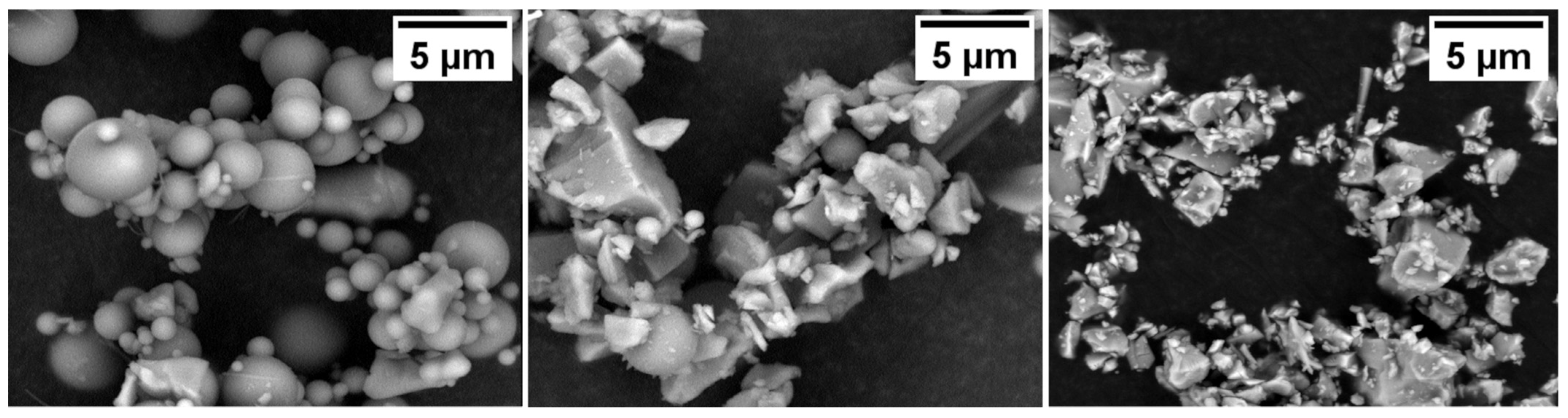
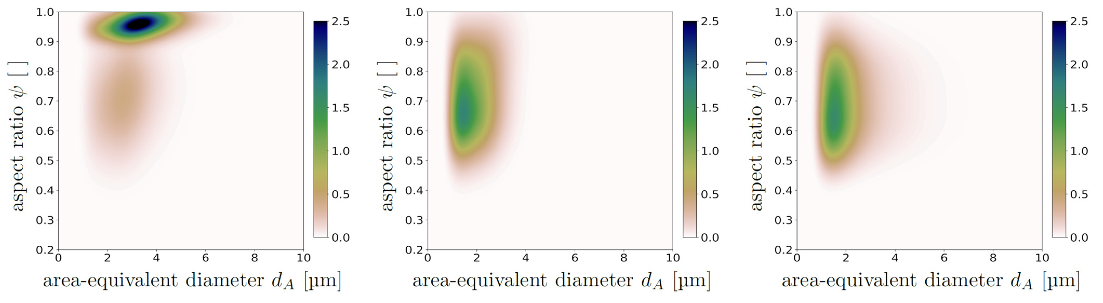
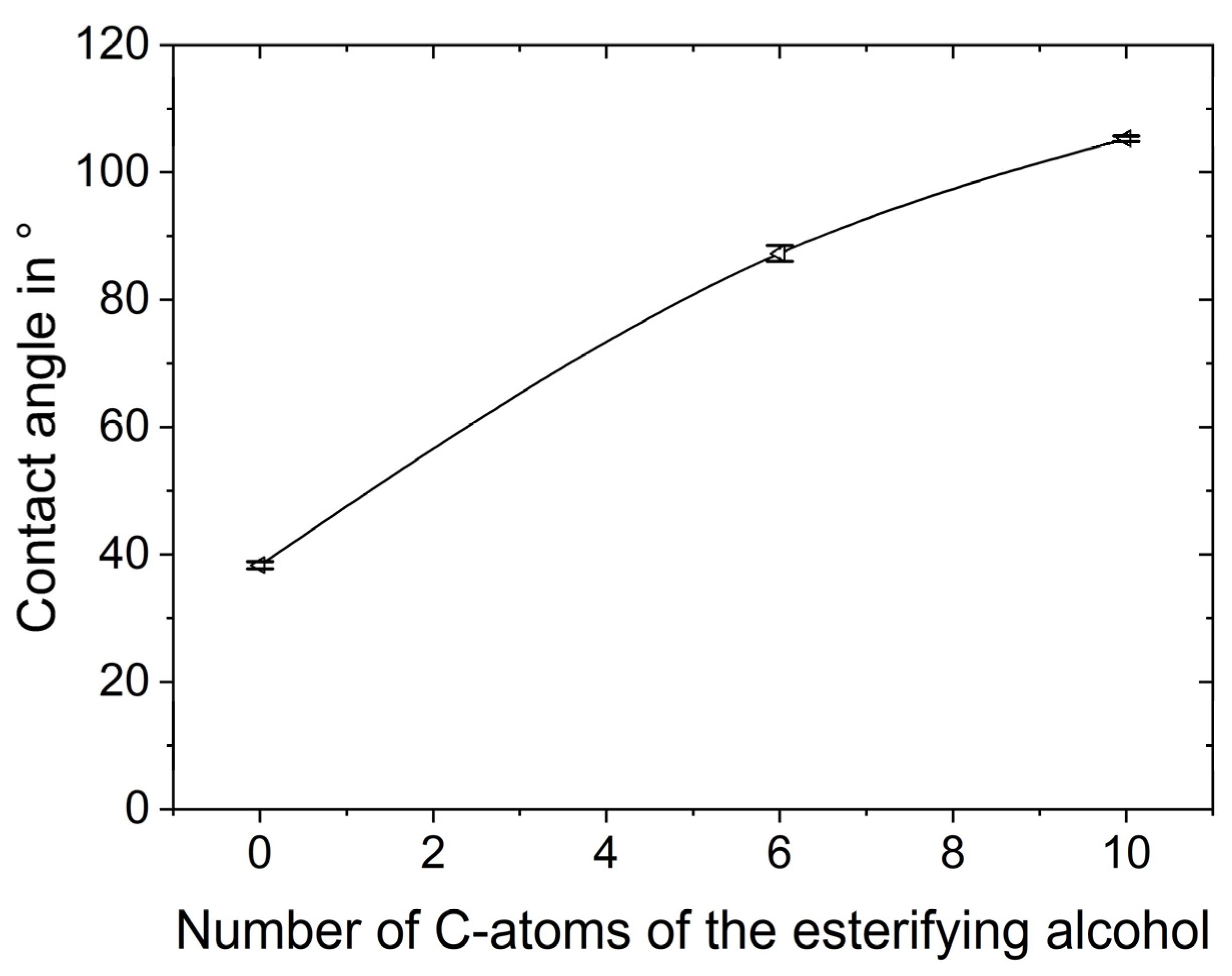
2.1. Materials

The particles used for the flotation tests are presented in SEM images in Figure 1. The feed material consisted of glass particles with two different morphologies, i.e., spheres and fragments, with the floatable and magnetite as the non-floatable fraction. Magnetite was purchased in an ultrafine size fraction (<10 µm) from Kremer Pigmente, Germany, and analysis via X-ray diffraction confirmed its purity. The glass spheres and fragments both consisted of soda-lime glass and were purchased from VELOX, Germany, as SG7010 and SG3000, respectively. The glass spheres were purchased in ultrafine size fractions (<10 µm) (SG7010), whereas glass fragments with sizes of <10 µm were obtained via the milling and aero classification of coarser glass spheres (SG3000). Figure 2 shows the bivariate distributions of their respective properties of size, here indicated as the area-equivalent diameter calculated in accordance with Equation (1), and shape, here indicated as the aspect ratio calculated as the ratio of the minimum Feret diameter to the maximum Feret diameter, both being obtained from image analysis.
a r e a e q u i v a l e n t   d i a m e t e r = 2 p r o j e c t e d   a r e a π
While the glass particles had a density of 2500 kg/m3, which results in a stationary settling velocity of νglass = 8.27 × 10⁻⁶ m/s, the magnetite had a much higher density of 5200 kg/m3 and therefore a faster settling velocity of νmagnetite = 2.31 × 10⁻⁵ m/s (calculated for the Stokes regime and spherical particles).
The wettability of the glass particles was modified via an esterification reaction with n-alcohols, where the resulting particle hydrophobicity was controlled via the alkyl chain length of the alcohol used, as shown by Sygusch et al. [30]. In the scope of this study, three different wettability states of glass particles are used for flotation: pristine, unesterified hydrophilic particles (C0), and particles functionalised using the primary alcohols 1-Hexanol (C6, Carl Roth ≥ 98%, used as received) and 1-Decanol (C10, Carl Roth ≥ 99%, used as received) resulting in esterified particles with medium and strong hydrophobicities. The respective contact angles of equally treated glass slides are presented in Figure 3.

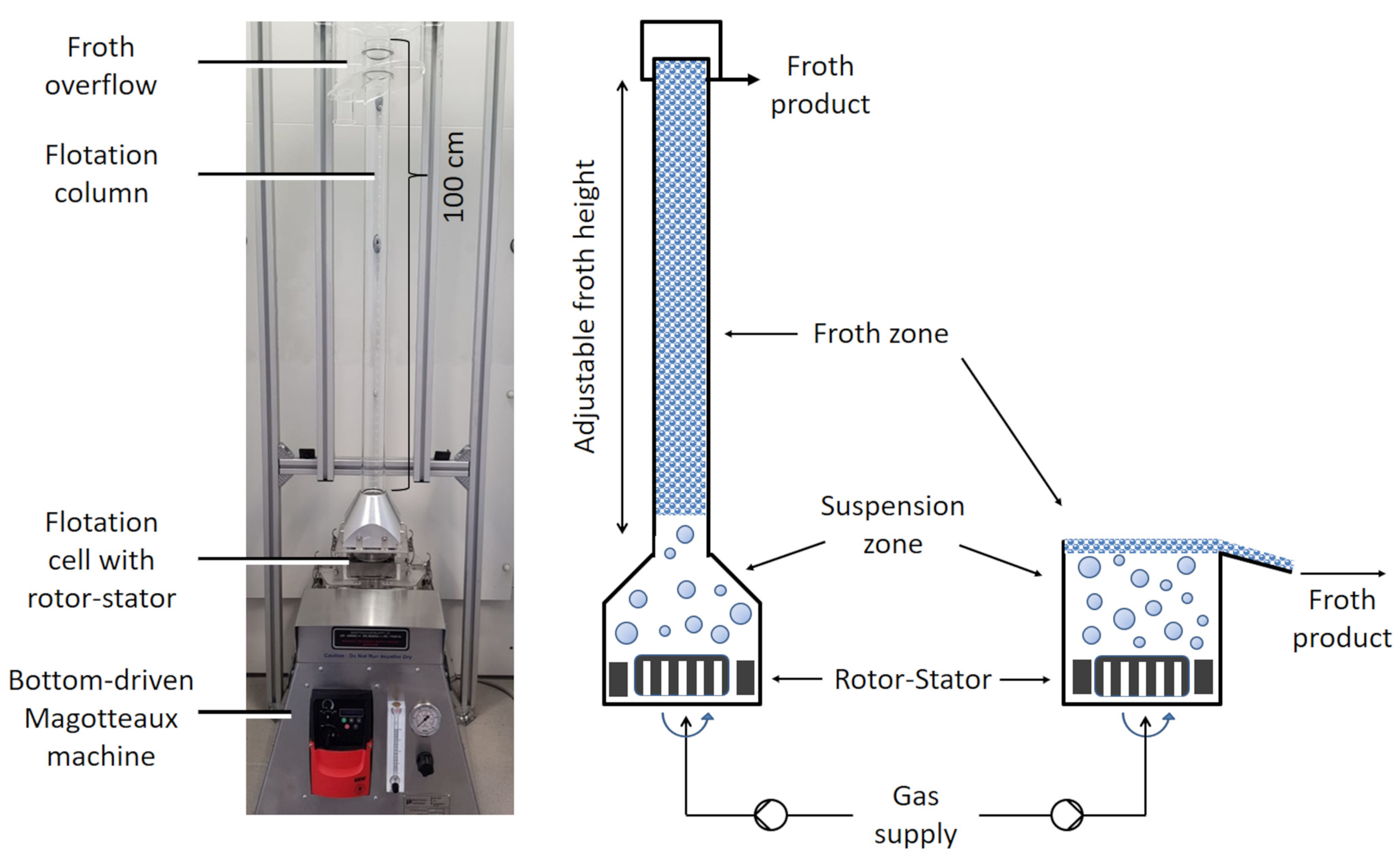
2.2. Separation Apparatus and Flotation Tests

A schematic drawing of the MultiDimFlot separation apparatus, which combines mechanical agitator-type froth flotation with column flotation, where the length of the column can be varied, is shown in Figure 4 together with the conventional mechanical froth flotation cell that is used as a benchmark. Both mechanical flotation cells (12 cm × 12 cm) with a rotor-stator system were purchased from Magotteaux, Vaux-sous-Chèvremont, Belgium.
The flotation tests were conducted in batch mode under comparable conditions with the same superficial gas velocity of 0.76 cm/s (different airflow rates due to different cross-sectional areas of the cells—MultiDimFlot apparatus: 0.9 L/min; mechanical flotation cell: 6.6 L/min) at a rotational speed of 600 min−1 for both cells. For all tests, a pulp density of 4.8% (w/w) was used with a weight ratio of the glass particles to magnetite of 1:9, respectively. Poly(ethylenglycol) (PEG, Carl Roth with a molecular weight of 10,000 g/mol) was used as a frother. Because particle wettability was modified prior to flotation, no conditioning was needed. The particles were dispersed in a 10−2 M KCl background solution with a PEG concentration of 10−5 M using Ultra Turrax (dispersion tool S25N-25F) from IKA, Staufen, Germany, for 1 min at 11,000 min−1. The resulting dispersion had a pH of 9. Flotation tests were carried out for 8 min with concentrates being taken after 1, 2, 4, 6, and 8 min by scraping off the froth every 10 s. For the case of the MultiDimFlot separation apparatus, the flotation tests were conducted using different column lengths of 100 cm, 80 cm and 60 cm, each with a diameter of 5 cm. Each setting was repeated at least 2 times. The post-processing of the concentrates and tailings included the centrifugation of the ultrafine particles, followed by gravimetric analysis for mass balancing and the X-ray fluorescence (S1 TITAN, Bruker, Billerica, MA, USA) of the dried samples.

3. Results and Discussion

The results of this study are presented in different subsections. In the first part, the results of the separation tests of the ultrafine model system using the newly developed separation apparatus with a column length of 100 cm (MultiDimFlot) are compared to those obtained when the conventional mechanical flotation cell is used. In the second part, the column length, i.e., froth depth, of the MultiDimFlot apparatus is varied.
It is assumed that, for the particle systems consisting of hydrophilic particles only, i.e., pristine glass particles and magnetite, there is no true flotation and that the particles are recovered by entrainment only. In this way, information on the influence of particle shape on the entrainment can be obtained. The entrainment factor ENT is calculated as the ratio of the maximum cumulative recovery of the gangue material to the maximum cumulative water pull. Because magnetite has a much higher density and therefore a faster settling velocity (ρmagnetite = 5200 kg/m3, νmagnetite = 2.31 × 10⁻⁵ m/s) than do the glass particles (ρglass = 2500 kg/m3, νglass = 8.27 × 10⁻⁶ m/s), it is more likely that the magnetite is drained back into the pulp more efficiently, which is why it is expected that more glass particles are recovered via entrainment than are magnetite for hydrophilic C0 systems. This is in addition to the fact that also a higher fraction of glass is reaching the pulp–froth interface as it is more equally mixed within the pulp along the height of the suspension zone via turbulent diffusion, which is essentially also a function of the settling velocity. The more hydrophobic glass particle fractions (C6 and C10) are expected to encounter true flotation phenomena, i.e., they interact with and actually attach to the bubbles and form stable particle–bubble aggregates that are recovered in the froth. However, since all particles of this study have size fractions well below 10 µm entrainment is expected to remain to be a significant component of the recovery mechanism. The selectivity index, SI, is calculated in accordance with Gaudin [31] as shown in Eqaution (2).
S I = R c u m , g l a s s 100 R c u m , m a g n e t i t e R c u m , m a g n e t i t e 100 R c u m , g l a s s

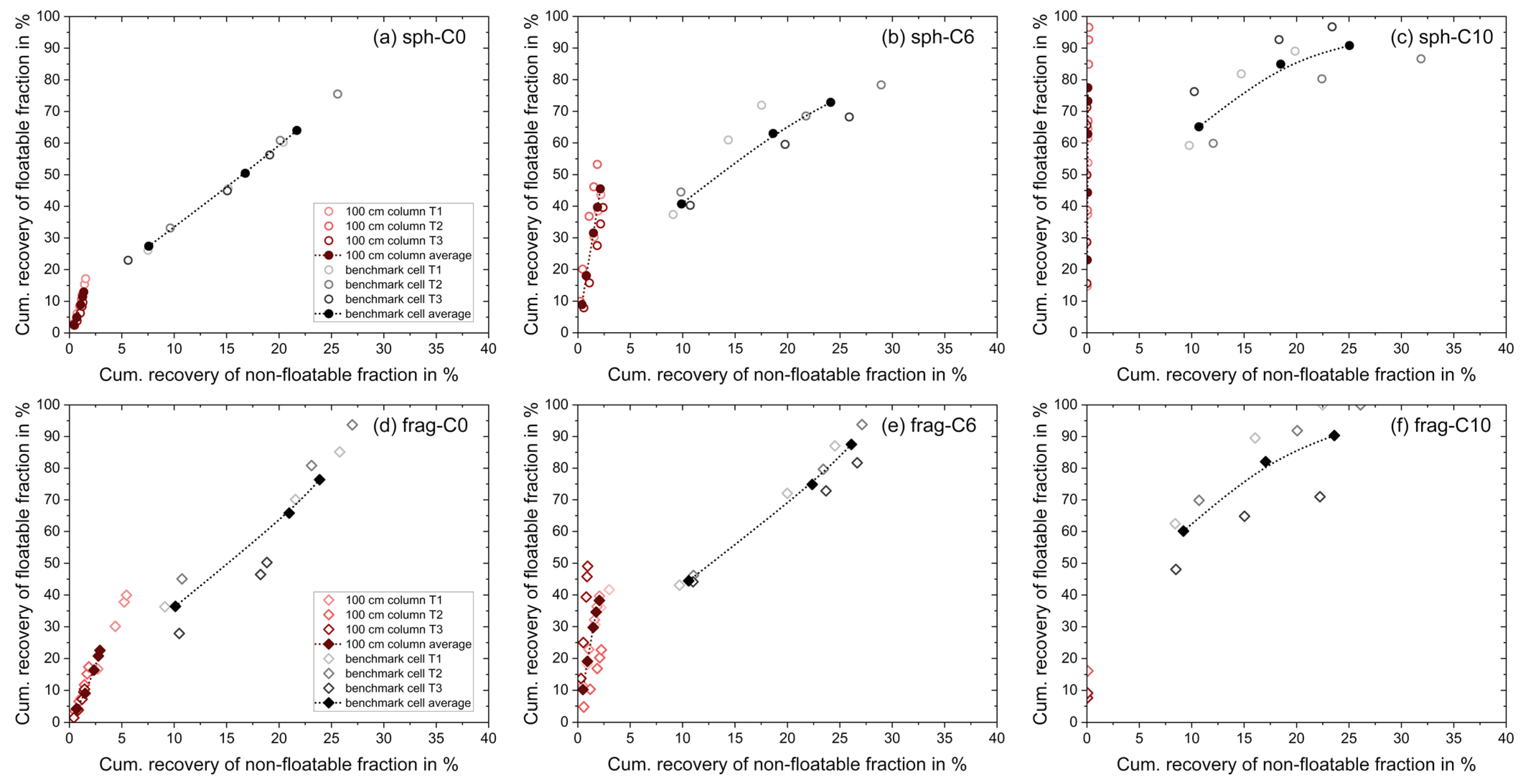
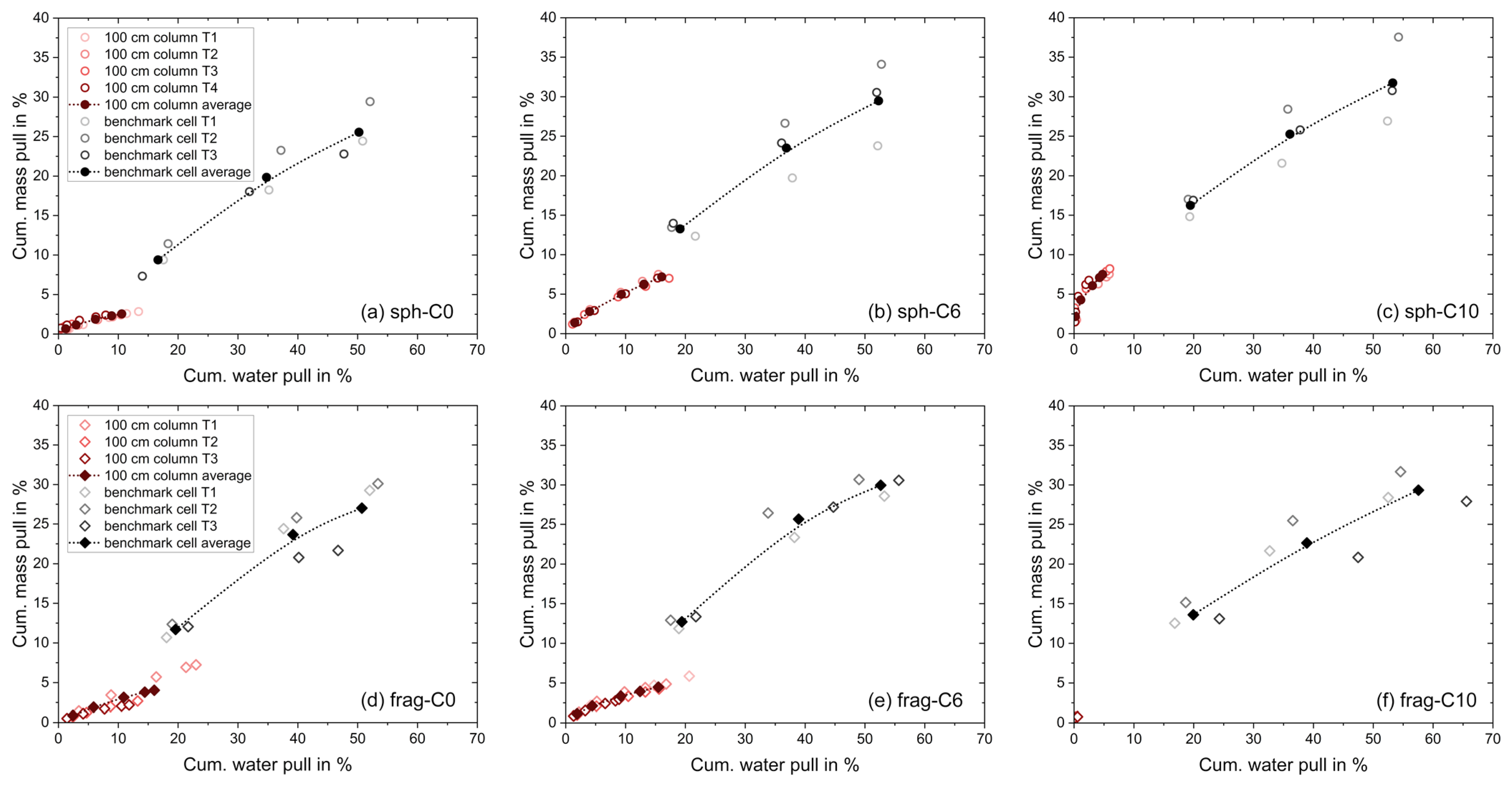
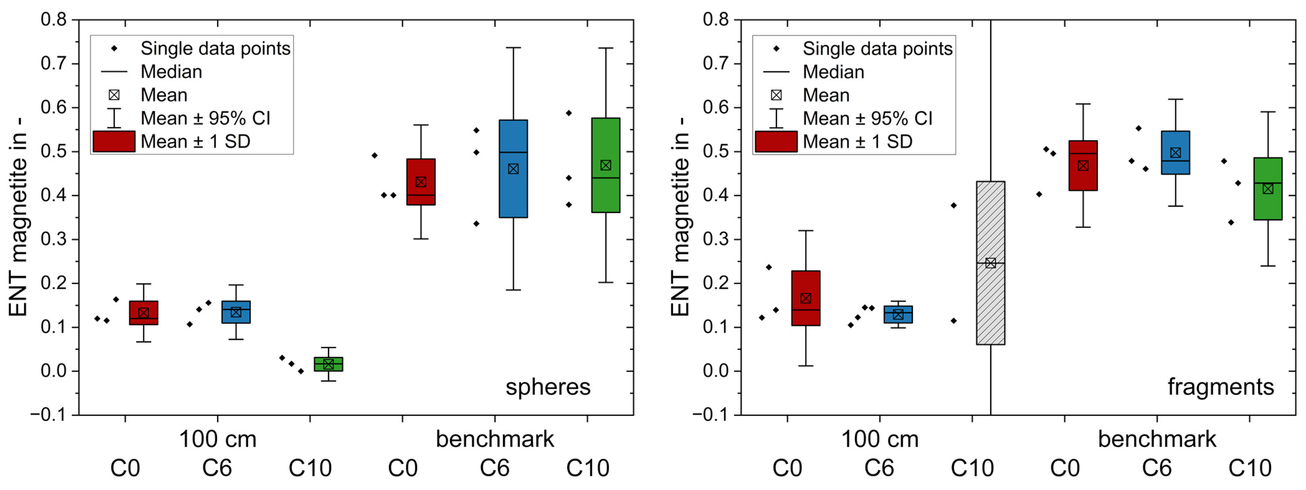
3.1. MultiDimFlot Apparatus vs. Benchmark Mechanical Flotation Cell

The results of the separation tests conducted in a benchmark mechanical flotation cell (black) and those conducted in the novel MultiDimFlot separation apparatus (red) are presented in Figure 5 as Fuerstenau plots, where the cumulative recovery of the glass particles is shown against the cumulative recovery of the magnetite particles. The top row displays the tests with glass spheres as the floatable fraction, whereas the bottom row displays the tests with glass fragments as the floatable fraction (with magnetite being the non-floatable fraction for both systems) and the hydrophobicity of the glass particles is increasing from C0 to C6 to C10 (left to right). Single unfilled, non-connected points represent the results of individual test runs, whereas the filled points that are connected with a line represent the average of said test runs. Each data point corresponds to the cumulative recovery after defined flotation times.
Flotation tests conducted in the benchmark mechanical cell generally have higher recoveries for the floatable fraction (glass), but also for the fraction that is not supposed to float (magnetite), when compared to the MultiDimFlot results. All the results of the benchmark cell are very similar despite the use of particle systems with differing properties, i.e., different shapes (spheres vs. fragments) and wettabilities (hydrophilic, C0; moderately hydrophobic, C6; strongly hydrophobic C10), showing that separation is not very selective on those ultrafine particle property vectors. Hence, recovery is more a consequence of the high mass and water pulls, which are displayed in Figure 6, and, furthermore, the recovery of the particles (also the floatable fraction) is governed by entrainment rather than true flotation. The high output of particles and water is most probably a result of the shallow froth (around 2 cm), which is common for mechanical flotation cells in batch lab operations.
In addition, there is a density effect, which is why more of the glass particles are recovered, or rather entrained, than are the magnetite particles. Flotation tests in a benchmark mechanical cell result in higher recoveries for glass fragments in two out of three cases, when compared to glass spheres (average values of maximum recoveries: Rspheres-C0 = 64% vs. Rfragments-C0 = 76%, Rspheres-C6 = 73% vs. Rfragments-C6 = 87%, and Rspheres-C10 = 91% vs. Rfragments-C10 = 90%). This confirms most of the studies on the impact of particle shape using a mechanical cell with shallow froth since non-spherical particles have a higher probability of being recovered mostly due to the more efficient micro-processes that occur in the suspension zone.
The separation tests in the MultiDimFlot apparatus on the other hand have a much lower mass and water pull. Considerably less magnetite is recovered, resulting in lower ENT values (see Figure 7) and a higher selectivity (see SI values in Table 1). This is most probably due to the deep froth and its fractionating effect in the MultiDimFlot cell since the unwanted particles are drained back into the pulp, thus increasing the grade of the concentrate.
These results support the previous findings of Taghavi et al. [32] who compared the flotation performance of phosphate slimes in a mechanical and a column flotation cell. They showed that the flotation of fine particles in a column was more selective as higher P2O5 grades were obtained, which was most probably due to the calm flow regime in the column and the long residence time of the particles in the deep froth, which increased their chances of reporting back to the suspension. Furthermore, the flotation results obtained with the MultiDimFlot apparatus showed higher sensitivity towards the different particle property vector components, e.g., hydrophilic particles (C0) were accompanied by a wetter froth than were hydrophobic particles (C6, C10) and recoveries increased with particle hydrophobicity, which suggests that more hydrophobic ultrafine glass particles are recovered also via true flotation instead of entrainment only.
When glass particles with different shapes are used, i.e., spheres vs. fragments, and the recoveries of particles with a similar wettability state are compared, it can be observed that there is not a general trend as to which shape is recovered more preferably. For the hydrophilic C0 system, the average recovery of spheres is only 13%, whereas the average recovery of fragments is 23%. Note that these are solely hydrophilic systems and that their recovery is supposed to occur via entrainment only. This is contrary to the studies of Little et al. [22], since they showed the opposite effect for hydrophilic chromite particles (which were coarser than the ultrafine particles studied here) as their entrainment increases with roundness.
For glass particles with a medium level of hydrophobicity (C6), the opposite results are obtained, as 45% of glass spheres and only 38% of glass fragments are recovered. These findings are, once more, not in agreement with those of previous studies where the common theory is that particles that have a rough surface and more edges can rupture the liquid film between the particle and the bubble more easily, thus having a higher probability of attachment, which in turn is expected to result in faster kinetics and higher recoveries of edgy and/or rough particles [16,17,19,33].
For strongly hydrophobic particle systems (C10), comparison is not as easy. Here, for glass spheres, recoveries of almost 100% are obtained, whereas only around 20% of glass fragments are recovered. The reason for this lies in the froth characteristics, which are strongly affected by the particle system and their accompanying properties. Johansson and Pugh [14] have shown that up to a certain degree of hydrophobicity, particles remain dispersed within the lamella (at contact angles, θ, below 40°) or attach to the interface (θ ≈ 65°) and can thus stabilise the froth, while too-hydrophobic particles (θ > 80°) cause bridging effects and penetrate the froth interface resulting in a rupture and thus bubble coalescence. Since both glass particle systems are strongly hydrophobic, this effect should in this study be observed both for the fragments and the spheres. However, this phenomenon was only observed to this extent for the C10 fragment system with MultiDimFlot, where only two concentrates were taken before the froth finally collapsed completely and thus resulted in a premature ending of the flotation test. For the -C10 fragment system, a wide bubble size distribution with very large polyhedral-like bubbles is observed causing bubble coalescence and finally the collapse of the froth. For the -C10 spheres system on the other hand, large bubbles are observed as well, but the bubbles are more spherical and the froth is more stable. This behaviour for the ultrafine particles of this study is quite noteworthy and can occur for two reasons; first, even though the modification of the particle wettability of the two glass fractions is carried out identically and should result in similar levels of wettability, there can be an influence of particle shape on the resulting hydrophobicity (cf. [30]). Ulusoy et al. [34] for example studied the influence of shape on the apparent hydrophobicity of calcite and barite particles that were milled in different ways and showed that more spherical particles of the same type exhibit lower apparent hydrophobicities than do more elongated and flat ones. Second, not only does hydrophobicity affect froth characteristics, but particle shape also plays a crucial role whether a froth is stabilised or destabilised. Several studies investigated how particle shape influences froth stability and showed that edgy and/or rough particles rupture the liquid film faster and that this effect occurs at much lower contact angles than those for spherical particles [35,36,37,38,39]. The reason is most probably a combination of both points. Since this phenomenon is related to the froth, it is only observed for the MultiDimFlot apparatus and not for the conventional mechanical flotation cell.
This shows once more that in order to understand the mechanisms at play during flotation, the process itself must be divided into at least two zones, a pulp or suspension and a froth zone, since both zones are affected by particle properties very differently, i.e., very hydrophobic particles will attach to the bubble in the pulp zone more effectively, resulting in higher recoveries, but will also destabilise the froth more easily which in turn reduces their recovery.

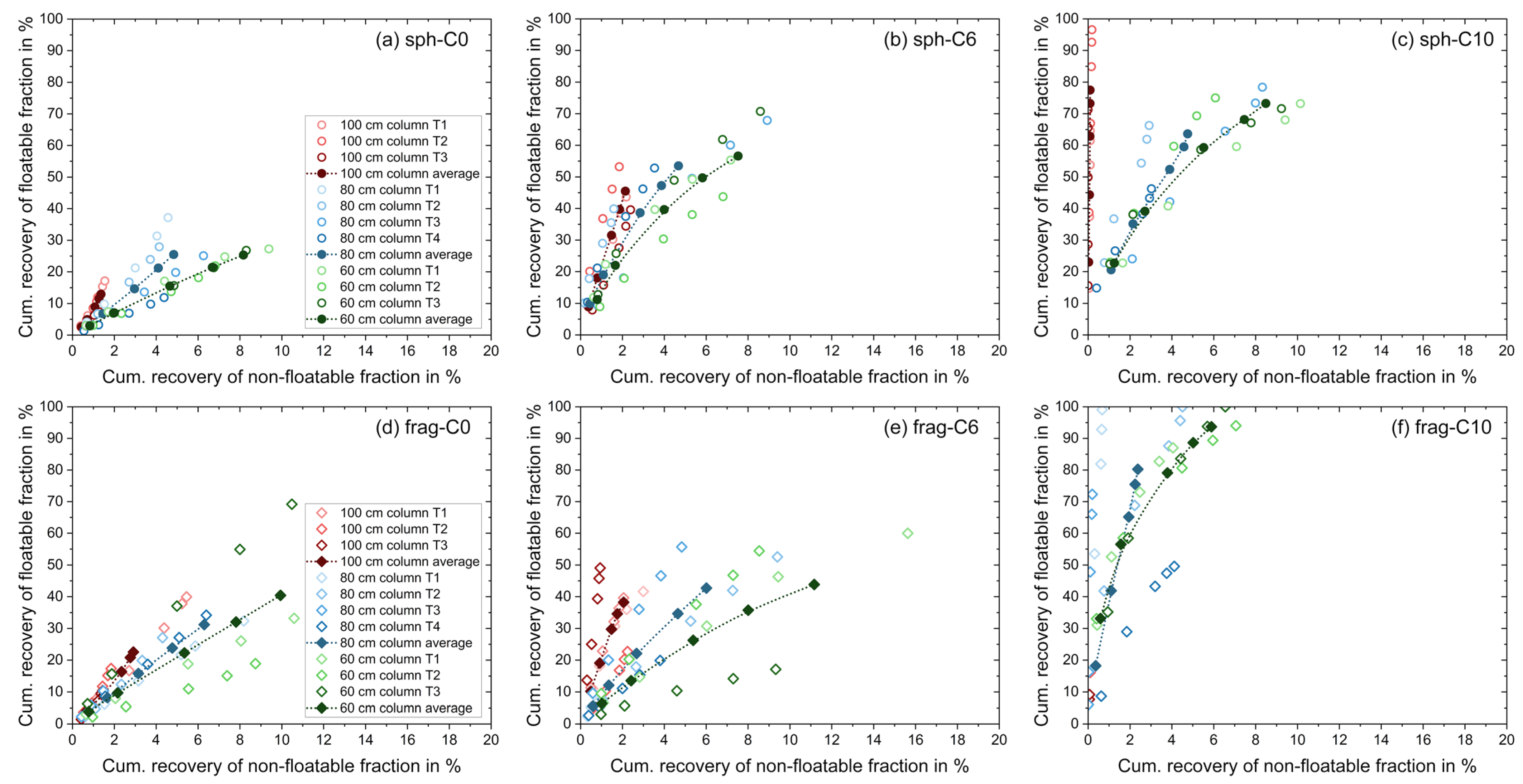
3.2. Influence of Froth Depth on the Flotation of Ultrafine Particles in the MultiDimFlot Cell

The second part of this study focuses on the influence of the froth depth for the MultiDimFlot separation apparatus only. For this, different column lengths with the length of 100 cm, 80 cm and 60 cm, resulting in froth depths of 75 cm, 50 cm and 20 cm, respectively, were used for the flotation tests, while the general apparatus set-up, process parameters and particle systems stayed the same.
Figure 8 displays the results of the flotation tests with the ultrafine model system using the MultiDimFlot cell with differing column lengths (a 100 cm column length in red, 80 cm column length in blue, 60 cm column length in green) as Fuerstenau plots.
The top row displays the tests with glass spheres as the floatable fraction, whereas the bottom row displays the tests with glass fragments as the floatable fraction (with magnetite being the non-floatable fraction for both systems) and the hydrophobicity of the glass particles increases from C0 to C6 and C10 (left to right). Single unfilled, non-connected points represent the results of individual test runs, whereas the filled points that are connected with a line represent the average of said test runs. Each data point corresponds to the cumulative recovery observed after defined flotation times.
Within a column system with the same length, the recovery of glass particles increases along with the hydrophobicity (RC0 < RC6 < RC10) for both spheres and fragments (except C10 fragments in the 100 cm column due to froth collapse), while the recovery of ultrafine hydrophilic magnetite is reduced. As the hydrophobicity of the valuable fraction increases, the froth becomes dryer and further loaded with particles as seen in Figure 9 (e.g., the average water recovery for the 60 cm column at a cum. mass pull of 10%: Rw,spheres-C0 ≈ 29%, Rw,spheres-C6 ≈ 22.5%, Rw,spheres-C10 ≈ 15%, Rw,fragments-C0 ≈ 27.5%, Rw,fragments-C6 ≈ 25%, and Rw,fragments-C10 ≈ 15%), which was also discovered by Ata et al. [40] who investigated the drainage behaviour in flotation froth and showed that particle hydrophobicity has a significant effect on the drainage rate of hydrophilic gangue particles.
If not only the total mass pull, but also the individual mass pull of glass particles and magnetite (cf. Figure 10 and Figure 11, respectively) are considered, it can be seen that the mass pull of magnetite in relation to water recovery is more or less linear for all flotation tests. This suggests that the dominant mechanism for the recovery of magnetite is entrainment, since ultrafine liberated particles are finely dispersed within the suspension and with increasing water recovery more particles are transported to the concentrate via the froth lamella, as shown by Engelbrecht and Woodburn [41] and Trahar [42] in the case of ultrafine silica and quartz particles, respectively.
Looking at the individual mass pull of the glass particles, one can clearly see the change in behaviour of the hydrophilic system toward the hydrophobic particle fractions. For the hydrophilic spheres and fragments (C0), a linear relation of mass and water pull is observed (just as it is for the magnetite particles), which would suggest that the hydrophilic ultrafine glass particles are recovered dominantly via entrainment. As the glass particles become more hydrophobic (C6 and C10), the mass pull follows a more degressively increasing trend, which suggests that the particles are recovered via true flotation, i.e., they actually attach to the gas bubbles and are recovered in the froth as a bubble–particle aggregate and not as part of the suspension within the lamella. Nevertheless, due to the fine particle size a certain degree of entrainment for these particles is always expected, even for very hydrophobic particles. Interestingly, while for the C0 and C10 systems a more or less similar increase and curve progression is observed, the mass–water pull relation of the C6 fragments has a less steep increase than does that of the C6 spheres, which consequently can be interpreted as a higher proportion of fragments being recovered via entrainment. The higher values of water recovery at similar mass pull levels for C6 fragments than for C6 spheres, i.e., wetter froth with fragments, are in support of this.
If the different particle shapes are compared for the same wettability level floated with the same column length, no general conclusion can be drawn from the results. For the hydrophilic system (C0), higher recoveries are obtained for fragments than for spheres for all tested column lengths. On the other hand, for the moderately hydrophobic (C6) particle system higher recoveries are obtained for spheres, again regardless of the froth depth. As already stated in the previous Section 3.1, these results are opposite of what has been reported in other studies. When strongly hydrophobic particles (C10) are tested, the column lengths of 60 cm and 80 cm yield higher recoveries for fragments than for spheres, whereas for the column length of 100 cm no comparison can be made due to the strong bubble coalescence and the resulting froth collapse for the C10 fragments. Here, it can be seen, that while for the C10 spheres the highest recoveries are obtained using the longest column of 100 cm with the deepest froth, for the C10 fragments the highest recoveries are obtained when the 80 cm column is used for flotation. This suggests that the optimum levels of wettability are different for the spheres and the fragments, thus making it shape-dependent.
The comparison of the different column lengths within one particle shape fraction with the same wettability state (e.g., C6 spheres in the 60 cm, 80 cm and 100 cm columns) shows that the average recovery of glass particles decreases with increasing froth depth. Only the strongly hydrophobic spheres (C10) show a different behaviour as the highest recovery is obtained with the deepest froth. At the same time, the amount of unwanted magnetite is reduced as the column length and thus the froth depth increases, i.e., the selectivity of the separation increases with the froth depth. This is supported by the results of the selectivity index, SI (see Table 1), which increases with froth depth for all particle systems as well as the entrainment factor, ENT, which decreases along with an increase in froth depth, as shown in Figure 12.
This is because the fractionating effect of the froth increases with its depth and the drainage effect that pulls back unwanted hydrophilic particles into the pulp is enhanced. Furthermore, Finch et al. [43] explain this with the increased coalescence of bubbles in higher regions in a froth profile which may enhance the selectivity because particles detach from the bubbles and only those with a certain level of hydrophobicity reattach to them, while others are drained back into the pulp. This idea is supported by Tao et al. [44] who suggest grade as a function of froth height. With this increased bubble coalescence in higher froth regions, Taghavi et al. [32] described a decrease in P2O5 recovery when the froth depth was increased, while at the same time they reported an increase in the P2O5 grade. Ata et al. [45] also investigated the influence of different froth heights using glass particles with a d50 of 68 µm with differing levels of hydrophobicity and showed, that the recovery of the different particle fractions is generally increased, but the extent of the increase and its trend depends on the wettability of said particles. They highlight that the residence time of the particles within the froth also plays an important role, as for their apparatus weakly hydrophobic particles have an optimum froth height, since a further increase results in reduced recoveries. The idea of increased bubble coalescence and an optimum froth height for a specific flotation apparatus and a particle system would also be suitable with regard to the behaviour of the -C10 fragments for the set-up of this study, where the bubbles are coalescing at a very fast rate leading to froth collapse and minimum recoveries.

3.3. General Discussion

In the previous two sections, the results of the flotation of a binary system of ultrafine glass particles with differing shapes as well as wettability and ultrafine magnetite were reported for the following scenarios. First, flotation in a newly developed separation apparatus that combines an agitator-type froth flotation cell with a column measuring 100 cm in length and flotation in a benchmark mechanical froth flotation cell was carried out under comparable conditions in order to evaluate the performance of the different apparatuses for ultrafine particle separation. Second, the column length of the MultiDimFlot cell was varied in order to study the effect of the froth depth. Both scenarios include a special focus on the particle property vectors of shape, wettability and size.
The comparison of the different separation cells (MultiDimFlot vs. benchmark mechanical cell) showed that the benchmark cell yields generally higher recoveries, but also poorer grades than does the MultiDimFlot cell, regardless of the particle system used. This was more or less expected, since it is known that a deep froth reduces the entrainment of hydrophilic gangue material [32,44,46]. Especially, flotation tests with the C0 particle systems, i.e., ultrafine hydrophilic valuable and gangue, where recovery is supposed to occur via entrainment only, revealed significant differences in the performance of the two apparatuses. While the mechanical froth flotation entrained an average of 65% of glass spheres and around 75% of glass fragments, MultiDimFlot with a 100 cm column only recovered an average of around 13% and 23% of the glass spheres and fragments, respectively (see Figure 5), which further supports the results of previous studies investigating the influence of different flotation set-ups. Interestingly, for all flotation set-ups, i.e., the mechanical cell as well as the MultiDimFlot cell with column lengths of 100 cm, 80 cm and 60 cm, higher recoveries via entrainment are obtained for the fragments, which is the opposite to what Little et al. [22] reported, as they showed that the entrainment of chromite increased with particle roundness and was lowest for elongated particles. Kupka et al. [23] had similar outcomes as the entrainment of quartz and titanite in an industrial rougher flotation bank of a scheelite beneficiation plant increased with their roundness. Note that a direct comparison of a self-built separation apparatus at lab scale, as is the case in this study, and two industrial flotation circuits is not straight-forward, and additionally that much coarser particle size fractions (in comparison to the ultrafine particles of this study) have been evaluated by Little et al. and Kupka et al., which might explain the different outcomes. On the other hand, Wiese et al. [24,47] reported that chromite fragments as well as elongated wollastonite particles with a needle-like shape entrained to a larger extent than did spherical ballotini. This is more in line with the results of this study and has also a better basis of comparison since Wiese et al. conducted flotation tests in batch mode at lab scale and the wollastonite, chromite and ballotini particles had sizes below 25 µm. Unfortunately, not many studies focus on the influence of particle shape on entrainment specifically, so the pool of literature for comparison is rather small.
When the hydrophobicity of glass particles is increased, their recovery also increases, which indicates that they are recovered via true flotation, although recovery via entrainment will still contribute. Interestingly, for the C6 system, i.e., the particles with medium hydrophobicity, higher recoveries are obtained for spheres when flotation is carried out in the MultiDimFlot apparatus regardless of the froth depth, while the conventional mechanical froth flotation cell yields higher average recoveries for fragments. Many studies have shown that edgy and/or rough particles have higher recoveries than do spherical particles, which is explained by the easier rupture of the liquid film between the bubble and the particle that results in more efficient bubble–particle collisions and finally attachment [16,17,18,20]. Therefore, the results of the mechanical froth flotation cell would support these studies. The reason for the opposite behaviour of the particles in MultiDimFlot most probably lies in the apparatus itself, since most of the previous studies were conducted in mechanical flotation cells which generally have very shallow froth or even, at micro flotation scale, do not take into account the froth phase at all. In contrast, MultiDimFlot combines the mechanical flotation cell with deep froth. Since froth properties, especially froth depth, have a significant effect on separation this might be the most suitable explanation for the different process outcomes. On the other hand, Kursun et al. [48] showed that the column flotation of talc particles yielded higher recoveries for more elongated and flat particles than it did for talc particles with higher roundness, which is again contradictory to the results of the MultiDimFlot cell. However, for their study they used a particle size fraction of −250 µm to +45 µm and specifically filtered out all particles with sizes smaller than 45 µm, which makes the comparison of the results more difficult. Comparing results of different studies is generally not straight-forward, since most of the flotation tests are conducted in different cells (a mechanical cell, micro-flotation, column flotation, a self-built apparatus, or an industrial plant) under different experimental parameters (rpm, air flow rate, froth washing, reagent regime, etc.) using different particle systems (composition, size distribution, liberation, wettability, etc.). Koh et al. [16] for example conducted their flotation tests in a 3-litre modified Denver cell with a rather high rpm and air flow rate of 1200 and 8 L/min, whereas Vaziri Hassas et al. [17] used a micro-flotation set-up. Parameters such as rpm and air flow rate can have a large impact, since the rpm and thus the degree of turbulence within the cell influences the collision, attachment and stability of the bubbles and the particles and the air flow rate affects the gas hold-up as well as the residence time of the froth and thus also drainage and entrainment. Furthermore, many studies use particles of much larger sizes, which might be problematic for comparison, as Rahimi et al. [49] showed that the influence of shape on the flotation kinetics is larger for coarser particles than for finer ones and that for smaller size fractions roughness is the more dominating property. This could lead to inconsistent flotation results when particle fractions of different sizes are used for testing. Particles with different levels of wettability are also hard to compare, since a change in hydrophobicity can have significant effects on the influence of shape, as seen in this study for the very hydrophobic particle systems (C10), where higher recoveries are obtained for fragments than for spheres, i.e., the particles show the opposite behaviour to that of those in the C6 system.
Since the process of flotation is rather complex, it is hard to attribute a certain effect directly to a single cause, since for example the properties of a particle system influence the froth characteristics. If the hydrophobicity of particles is changed, this will not only influence the micro-processes (e.g., leading to a higher attachment probability) in the suspension zone but also eventually affect the froth, which in turn will also have consequences on separation. This was demonstrated in this study when the 100 cm column length together with the strongly hydrophobic fragments (C10) were used, as they destabilised the froth which resulted in its complete collapse and hence very low recovery. The fact that this phenomenon was observed for the strongly hydrophobic fragments only and not for the spheres with similar hydrophobicity levels also demonstrates the influence of particle shape on the apparent hydrophobicity of particles and their effect on the froth, and supports investigations from Dippenaar [36] who showed that particles with a spherical shape need to have higher contact angles in order to rupture the liquid film than do non-spherical particles. This suggests that there is not only an optimum contact angle for the flotation of a certain size fraction of particles as shown by Johansson et al. [14] and Schwarz et al. [50] for quartz particles, but that the optimum contact angle is also shape-dependent, as seen in this study. Johansson et al. used a size fraction of 26–44 µm and reported an optimum contact angle of around 65° for which the froth stability was highest, while Schwarz et al. used quartz of a size fraction of −38 µm and reported an optimum contact angle of around 63° for maximum recovery. Both investigations showed that a further increase in contact angle (θ > 80° for Johansson et al. and θ = 69° for Schwarz et al.) results in increased froth collapse and reduced recovery. According to their outcomes, the C6 particle fractions with medium hydrophobicity of this study with a contact angle of 87° should already be too hydrophobic for efficient flotation and the strongly hydrophobic C10 fractions with a contact angle of 105° should be even less suitable. However, as highlighted here, except for the C10 fragments all of the studied fractions are floatable with the highest hydrophobicity level even yielding the highest recoveries. This suggests that the optimum contact angle changes not only with particle shape but also with the particle size.

4. Conclusions

This study investigated the influence of the particle property vectors of shape, wettability and size as a contribution to the further understanding and improvement of the flotation specifically of ultrafine particles. A novel flotation apparatus, the MultiDimFlot cell, designed for ultrafine particle treatment and increasing our understanding of suspension and froth zone separation, is applied combining high particle–bubble collision rates of a conventional froth flotation cell with high selectivities via fractionation in deep froth of column flotation. Flotation tests were also carried out in a benchmark agitator-type froth flotation cell under comparable conditions in order to evaluate the performance of this newly developed separation apparatus specifically for the separation of ultrafine particulate systems. By altering the wettability of the floatable fraction via esterification with alcohols, six academic feed systems of glass particles with two different morphologies as well as three different wettability states mixed with magnetite as the non-floatable fraction are available for testing.
In agreement with our common understanding of the flotation process, our results show that recoveries increase when particles are hydrophobised, but in addition they point out that optimum levels of hydrophobicity vary for different particle shapes as a consequence of particle–froth interaction, also depending on the separation apparatus used. While the recovery of particles with medium hydrophobicity was more pronounced for spheres when the MultiDimFlot apparatus was used, the benchmark froth flotation cell recovered more of the fragments. On the other hand, if strongly hydrophobic glass particles are used the opposite trend is obtained. The entrainment of the floatable glass fractions within the purely hydrophilic feed system was generally higher for fragments than for spheres. For the separation of ultrafine particulate material, the newly developed MultiDimFlot separation apparatus yielded lower recoveries than did the agitator-type froth flotation cell, but the concentrates had higher grades and the results showed a much higher sensitivity towards the investigated ultrafine particle property vectors of wettability and shape. The entrainment of unwanted ultrafine hydrophilic magnetite is reduced as the froth depth is increased.

Author Contributions

Conceptualisation, J.S. and M.R.; methodology, J.S. and M.R.; formal analysis, J.S. and N.S.; investigation, J.S. and N.S.; writing—original draft preparation, J.S.; writing—review and editing, N.S. and M.R.; visualisation, J.S.; supervision, M.R.; funding acquisition, J.S. and M.R. All authors have read and agreed to the published version of the manuscript.

Funding

This work was supported by the German Research Foundation (DFG) via the research project RU 2184/1-1 and RU 2184/1-2 as part of the priority programme SPP2045, “Highly specific and multidimensional fractionation of fine particle systems with technical relevance”.

Data Availability Statement

The data presented in this study are available on request from the corresponding author.

Acknowledgments

The authors would like to thank Nyamjargal Erdeneduvchir, Mujahid Hussain Bhatti and Klaus Graebe from the Helmholtz Institute Freiberg for Resource Technology for their assistance in the lab, as well as Thomas Wilhelm from the Institute of Stochastics from Ulm University for generating the bivariate distributions.

Conflicts of Interest

The authors declare no conflict of interest.

References

  1. Wills, B.A.; Finch, J.A. Wills’ Mineral Processing Technology, Froth Flotation; Elsevier: Amsterdam, The Netherlands, 2016; Chapter 12; pp. 265–380. [Google Scholar]
  2. Schubert, H. Aufbereitung fester Stoffe, Band II: Sortierprozesse; Deutscher Verlag für Grundstoffindustrie: Stuttgart, Germany, 1996. [Google Scholar]
  3. Pradip; Fuerstenau, D.W. The role of inorganic and organic reagents in the flotation separation of rare-earth ores. Int. J. Miner. Process. 1991, 32, 1–22. [Google Scholar] [CrossRef]
  4. Ralston, J.; Fornasiero, D.; Hayes, R. Bubble–particle attachment and detachment in flotation. Int. J. Miner. Process. 1999, 56, 133–164. [Google Scholar] [CrossRef]
  5. Schubert, H.; Bischofberger, C. On the hydrodynamics of flotation machines. Int. J. Miner. Process. 1978, 5, 131–142. [Google Scholar] [CrossRef]
  6. Schubert, H. On the optimization of hydrodynamics in fine particle flotation. Miner. Eng. 2008, 21, 930–936. [Google Scholar] [CrossRef]
  7. Trahar, W.J.; Warren, L.J. The flotability of very fine particles—A review. Int. J. Miner. Process. 1976, 3, 103–131. [Google Scholar] [CrossRef]
  8. Miettinen, T.; Ralston, J.; Fornasiero, D. The limits of fine particle flotation. Miner. Eng. 2010, 23, 420–437. [Google Scholar] [CrossRef]
  9. Wang, L.; Peng, Y.; Runge, K.; Bradshaw, D. A review of entrainment: Mechanisms, contributing factors and modelling in flotation. Miner. Eng. 2015, 70, 77–91. [Google Scholar] [CrossRef]
  10. Yianatos, J.B. Column Flotation—Modelling and Technology. In Developments in Froth Flotation; SAIMM: Cape-Town, South Africa, 1989. [Google Scholar]
  11. Amini, E.; Bradshaw, D.J.; Xie, W. Influence of flotation cell hydrodynamics on the flotation kinetics and scale up, Part 2: Introducing turbulence parameters to improve predictions. Miner. Eng. 2017, 100, 31–39. [Google Scholar] [CrossRef]
  12. Albijanic, B.; Ozdemir, O.; Nguyen, A.V.; Bradshaw, D. A review of induction and attachment times of wetting thin films between air bubbles and particles and its relevance in the separation of particles by flotation. Adv. Colloid Interface Sci. 2010, 159, 1–21. [Google Scholar] [CrossRef]
  13. Drelich, J.W.; Marmur, A. Meaningful contact angles in flotation systems: Critical analysis and recommendations. Surf. Innov. 2017, 6, 19–30. [Google Scholar] [CrossRef]
  14. Johansson, G.; Pugh, R.J. The influence of particle size and hydrophobicity on the stability of mineralized froths. Int. J. Miner. Process. 1992, 34, 1–21. [Google Scholar] [CrossRef]
  15. Ata, S.; Ahmed, N.; Jameson, G.J. A study of bubble coalescence in flotation froths. Int. J. Miner. Process. 2003, 72, 255–266. [Google Scholar] [CrossRef]
  16. Koh, P.T.L.; Hao, F.P.; Smith, L.K.; Chau, T.T.; Bruckard, W.J. The effect of particle shape and hydrophobicity in flotation. Int. J. Miner. Process. 2009, 93, 128–134. [Google Scholar] [CrossRef]
  17. Vaziri Hassas, B.; Caliskan, H.; Guven, O.; Karakas, F.; Cinar, M.; Celik, M.S. Effect of roughness and shape factor on flotation characteristics of glass beads. Colloids Surf. A Physicochem. Eng. Asp. 2016, 492, 88–99. [Google Scholar] [CrossRef]
  18. Verrelli, D.I.; Bruckard, W.J.; Koh, P.T.L.; Schwarz, M.P.; Follink, B. Particle shape effects in flotation. Part 1: Microscale experimental observations. Miner. Eng. 2014, 58, 80–89. [Google Scholar] [CrossRef]
  19. Xia, W. Role of particle shape in the floatability of mineral particle: An overview of recent advances. Powder Technol. 2017, 317, 104–116. [Google Scholar] [CrossRef]
  20. Lu, S.; Pugh, R.J.; Forssberg, E. Interfacial Separation of Particles; Elsevier: Amsterdam, The Netherlands, 2005. [Google Scholar]
  21. Chen, Y.; Zhuang, L.; Zhang, Z. Effect of particle shape on particle-bubble interaction behavior: A computational study using discrete element method. Colloids Surfaces A Physicochem. Eng. Asp. 2022, 653, 13003. [Google Scholar] [CrossRef]
  22. Little, L.; Wiese, J.; Becker, M.; Mainza, A.; Ross, V. Investigating the effects of particle shape on chromite entrainment at a platinum concentrator. Miner. Eng. 2016, 96–97, 46–52. [Google Scholar] [CrossRef]
  23. Kupka, N.; Tolosana-Delgado, R.; Schach, E.; Bachmann, K.; Heinig, T.; Rudolph, M. R as an environment for data mining of process mineralogy data: A case study of an industrial rougher flotation bank. Miner. Eng. 2020, 146, 106111. [Google Scholar] [CrossRef]
  24. Wiese, J.; Becker, M.; Yorath, G.; O’Connor, C. An investigation into the relationship between particle shape and entrainment. Miner. Eng. 2015, 83, 211–216. [Google Scholar] [CrossRef]
  25. Dai, Z.; Fornasiero, D.; Ralston, J. Particle-bubble collision models—A review. Adv. Colloid Interface Sci. 2000, 85, 231–256. [Google Scholar] [CrossRef] [PubMed]
  26. Farrokhpay, S.; Filippova, I.; Filippov, L.; Picarra, A.; Rulyov, N.; Fornasiero, D. Flotation of fine particles in the presence of combined microbubbles and conventional bubbles. Miner. Eng. 2020, 155, 106439. [Google Scholar] [CrossRef]
  27. De Gontijo, C.F.; Fornasiero, D.; Ralston, J. The limits of fine and coarse particle flotation. Can. J. Chem. Eng. 2007, 85, 739–747. [Google Scholar] [CrossRef]
  28. Konopacka, Z.; Drzymala, J. Types of particles recovery—Water recovery entrainment plots useful in flotation research. Adsorption 2010, 16, 313–320. [Google Scholar] [CrossRef]
  29. Leistner, T.; Peuker, U.A.; Rudolph, M. How gangue particle size can affect the recovery of ultrafine and fine particles during froth flotation. Miner. Eng. 2017, 109, 1–9. [Google Scholar] [CrossRef]
  30. Sygusch, J.; Rudolph, M. A contribution to wettability and wetting characterisation of ultrafine particles with varying shape and degree of hydrophobization. Appl. Surf. Sci. 2021, 566, 150725. [Google Scholar] [CrossRef]
  31. Gaudin, A.M. Principles of Mineral Dressing; McGraw-Hill: New York, NY, USA, 1939. [Google Scholar]
  32. Taghavi, F.; Noaparast, M.; Pourkarimi, Z.; Nakhaei, F. Comparison of mechanical and column flotation performances on recovery of phosphate slimes in presence of nano-microbubbles. J. Cent. South Univ. 2022, 29, 102–115. [Google Scholar] [CrossRef]
  33. Szczerkowska, S.; Wiertel-Pochopien, A.; Zawala, J.; Larsen, E.; Kowalczuk, P.B. Kinetics of froth flotation of naturally hydrophobic solids with different shapes. Miner. Eng. 2018, 121, 90–99. [Google Scholar] [CrossRef]
  34. Ulusoy, U.; Hiçyılmaz, C.; Yekeler, M. Role of shape properties of calcite and barite particles on apparent hydrophobicity. Chem. Eng. Process. Process Intensif. 2004, 43, 1047–1053. [Google Scholar] [CrossRef]
  35. Aveyard, R.; Binks, B.P.; Fletcher, P.D.I.; Peck, T.G.; Rutherford, C.E. Aspects of aqueous foam stability in the presence of hydrocarbon oils and solid particles. Adv. Colloid Interface Sci. 1994, 48, 93–120. [Google Scholar] [CrossRef]
  36. Dippenaar, A. The destabilization of froth by solids. I. The mechanism of film rupture. Int. J. Miner. Process. 1982, 9, 1–14. [Google Scholar] [CrossRef]
  37. Ata, S. Phenomena in the froth phase of flotation—A review. Int. J. Miner. Process. 2012, 102–103, 1–12. [Google Scholar] [CrossRef]
  38. Farrokhpay, S. The significance of froth stability in mineral flotation—A review. Adv. Colloid Interface Sci. 2011, 166, 1–7. [Google Scholar] [CrossRef] [PubMed]
  39. Kaptay, G. On the optimum contact angle of stability of foams by particles. Adv. Colloid Interface Sci. 2012, 170, 87–88. [Google Scholar] [CrossRef]
  40. Ata, S.; Ahmed, N.; Jameson, G.J. The effect of hydrophobicity on the drainage of gangue minerals in flotation froths. Miner. Eng. 2004, 17, 897–901. [Google Scholar] [CrossRef]
  41. Engelbrecht, J.A.; Woodburn, E.T. The Effects of Froth Height, Aeration Rate and Gas Precipitation on Flotation. J. S. Afr. Inst. Min. Metall. 1975, 76, 125–132. [Google Scholar]
  42. Trahar, W.J. A rational interpretation of the role of particle size in flotation. Int. J. Miner. Process. 1981, 8, 289–327. [Google Scholar] [CrossRef]
  43. Finch, J.A.; Yianatos, J.; Dobby, G. Column Froths. Miner. Process. Extr. Metall. Rev. 1989, 5, 281–305. [Google Scholar] [CrossRef]
  44. Tao, D.; Luttrell, G.H.; Yoon, R.H. A parametric study of froth stability and its effect on column flotation of fine particles. Int. J. Miner. Process. 2000, 59, 25–43. [Google Scholar] [CrossRef]
  45. Ata, S.; Ahmed, N.; Jameson, G.J. Collection of hydrophobic particles in the froth phase. Int. J. Miner. Process. 2002, 64, 101–122. [Google Scholar] [CrossRef]
  46. McKay, J.D.; Foot, D.G.; Huiatt, J.L. Column flotation of Montana chromite ore. Min. Metall. Explor. 1986, 3, 170–177. [Google Scholar] [CrossRef]
  47. Wiese, J.G.; O’Connor, C.T. An investigation into the relative role of particle size, particle shape and froth behaviour on the entrainment of chromite. Int. J. Miner. Process. 2016, 156, 127–133. [Google Scholar] [CrossRef]
  48. Kursun, H.; Ulusoy, U. Influence of shape characteristics of talc mineral on the column flotation behavior. Int. J. Miner. Process. 2006, 78, 262–268. [Google Scholar] [CrossRef]
  49. Rahimi, M.; Dehghani, F.; Rezai, B.; Aslani, M.R. Influence of the roughness and shape of quartz particles on their flotation kinetics. Int. J. Miner. Metall. Mater. 2012, 19, 284–289. [Google Scholar] [CrossRef]
  50. Schwarz, S.; Grano, S. Effect of particle hydrophobicity on particle and water transport across a flotation froth. Colloids Surf. A Physicochem. Eng. Asp. 2005, 256, 157–164. [Google Scholar] [CrossRef]
Figure 1. Scanning electron micrographic images of glass spheres (left), glass fragments (middle) and magnetite (right).
Minerals 13 01099 g001
Figure 2. Bivariate distribution of the particle properties of shape, as aspect ratio, and size, as area-equivalent diameter, obtained via the image analysis of glass spheres (left), glass fragments (middle) and magnetite (right). The colour scale is an indication of the frequency of the described property value and has no units.
Minerals 13 01099 g002
Figure 3. Contact angles of pristine glass slides (C0) and those esterified with 1-Hexanol (C6) and 1-Decanol (C10) measured in sessile drop mode via optical contour analysis against water. The glass slides have the same chemical composition as do the glass particles used in this study and their esterification is conducted in the same way as that of the glass particles. The error bars represent the 95% confidence interval. Lines are added to guide the eyes.
Minerals 13 01099 g003
Figure 4. The MultiDimFlot separation apparatus in the lab (left), schematic drawings of MultiDimFlot (middle) and the conventional agitator-type froth flotation cell (right) used for the flotation tests in this comparative study.
Minerals 13 01099 g004
Figure 5. Fuerstenau upgrading curves for the flotation tests in the benchmark mechanical froth flotation cell (black) and the MultiDimFlot apparatus with the 100 cm column (red) using the 6-particle systems: (a) hydrophilic spheres, C0, (b) moderately hydrophobic spheres, C6, (c) strongly hydrophobic spheres, C10, (d) hydrophilic fragments, C0, (e) moderately hydrophobic fragments, C6, and (f) strongly hydrophobic fragments, C10, all mixed with magnetite as the non-floatable fraction. Data points for tests using spheres are represented by a circle, while data points for tests using fragments are represented by a diamond symbol. Filled points with a dashed line are average values (where lines were added to guide the eye), and single points are the individual experiment runs. Each data point corresponds to the cumulative recovery after defined flotation times.
Minerals 13 01099 g005
Figure 6. Cumulative mass versus water pull diagrams for the flotation tests in the benchmark mechanical froth flotation cell (black) and the MultiDimFlot apparatus with the 100 cm column (red) using the 6-particle systems: (a) hydrophilic spheres, C0, (b) moderately hydrophobic spheres, C6, (c) strongly hydrophobic spheres, C10, (d) hydrophilic fragments, C0, (e) moderately hydrophobic fragments, C6, and (f) strongly hydrophobic fragments, C10, all mixed with magnetite as the non-floatable fraction. Data points for tests using spheres are represented by a circle, while data points for tests using fragments are represented by a diamond symbol. Filled points with a dashed line are average values (where lines are added to guide the eye), and single points are the individual experiment runs. Each data point corresponds to the cumulative mass or water pull after defined flotation times.
Minerals 13 01099 g006
Figure 7. Entrainment factor, ENT, of the non-floatable fraction magnetite for the flotation tests in the MultiDimFlot apparatus with the 100 cm column and the benchmark mechanical froth flotation cell using spheres (left) and fragments (right) as the floatable fraction with increasing hydrophobicity from C0 (red) to C6 (blue) and C10 (green). The ENTs of the tests using fragments, C10, in MultiDimFlot are marked in grey, because only two tests worked out (others failed due to froth collapse), making the use of statistical analysis difficult.
Minerals 13 01099 g007
Figure 8. Fuerstenau upgrading curves for the flotation tests in the MultiDimFlot apparatus with the 100 cm column (red), the 80 cm column (blue) and the 60 cm column (green) using the 6-particle systems: (a) hydrophilic spheres, C0, (b) moderately hydrophobic spheres, C6, (c) strongly hydrophobic spheres, C10, (d) hydrophilic fragments, C0, (e) moderately hydrophobic fragments, C6, and (f) strongly hydrophobic fragments, C10, all mixed with magnetite as the non-floatable fraction. Data points for tests using spheres are represented by a circle, while data points for tests using fragments are represented by a diamond symbol. Filled points with a dashed line are average values (where lines are added to guide the eye), and single points are the individual experiment runs. Each data point corresponds to the cumulative recovery observed after defined flotation times.
Minerals 13 01099 g008
Figure 9. Cumulative mass versus water pull diagrams for the flotation tests in the MultiDimFlot apparatus with the 100 cm column (red), 80 cm column (blue) and the 60 cm column (green) using the 6-particle systems: (a) hydrophilic spheres, C0, (b) moderately hydrophobic spheres, C6, (c) strongly hydrophobic spheres, C10, (d) hydrophilic fragments, C0, (e) moderately hydrophobic fragments, C6, and (f) strongly hydrophobic fragments, C10, all mixed with magnetite as the non-floatable fraction. Data points for tests using spheres are represented by a circle, while data points for tests using fragments are represented by a diamond symbol. Filled points with a dashed line are average values (where lines are added to guide the eye), and single points are the individual experiment runs. Each data point corresponds to the cumulative mass or water pull observed after defined flotation times.
Minerals 13 01099 g009
Figure 10. Cumulative mass pull of magnetite only versus water pull diagrams for the flotation tests in the MultiDimFlot apparatus with the 100 cm column (red), 80 cm column (blue) and the 60 cm column (green) using the 6-particle systems: (a) hydrophilic spheres, C0, (b) moderately hydrophobic spheres, C6, (c) strongly hydrophobic spheres, C10, (d) hydrophilic fragments, C0, (e) moderately hydrophobic fragments, C6, and (f) strongly hydrophobic fragments, C10, all mixed with magnetite as the non-floatable fraction. Filled points with a dashed line are average values (where lines are added to guide the eye), and single points are the individual experiment runs. Each data point corresponds to the cumulative mass or water pull observed after defined flotation times.
Minerals 13 01099 g010
Figure 11. Cumulative mass pull of glass particles only versus water pull diagrams for the flotation tests in the MultiDimFlot apparatus with the 100 cm column (red), 80 cm column (blue) and the 60 cm column (green) using the 6-particle systems: (a) hydrophilic spheres, C0, (b) moderately hydrophobic spheres, C6, (c) strongly hydrophobic spheres, C10, (d) hydrophilic fragments, C0, (e) moderately hydrophobic fragments, C6, and (f) strongly hydrophobic fragments, C10, all mixed with magnetite as the non-floatable fraction. Data points for tests using spheres are represented by a circle, while data points for tests using fragments are represented by a diamond symbol. Filled points with a dashed line are average values (where lines are added to guide the eye), and single points are the individual experiment runs. Each data point corresponds to the cumulative mass or water pull observed after defined flotation times.
Minerals 13 01099 g011
Figure 12. Entrainment factor, ENT, of the non-floatable fraction magnetite for the flotation tests in the MultiDimFlot apparatus with the 100 cm column, the 80 cm column and the 60 cm column using spheres (left) and fragments (right) as the floatable fraction with increasing hydrophobicity from C0 (red) to C6 (blue) to C10 (green). The ENTs of the tests using C10 fragments in MultiDimFlot are marked in grey, because only two tests worked out (others failed due to froth collapse), which makes the use of statistical analysis difficult.
Minerals 13 01099 g012
Table 1. Selectivity index, SI, for the flotation tests conducted in the 4 different apparatus set-ups using different glass particles as the floatable fraction and magnetite as the non-floatable fraction.
Flotation ApparatusFloatable FractionAverage SI in
benchmark mechanical froth flotation cellSpheres, C02.59
Spheres, C62.98
Spheres, C106.43
Fragments, C04.17
Fragments, C64.80
Fragments, C102.92
MultiDimFlot apparatus—100 cm columnSpheres, C03.26
Spheres, C66.28
Spheres, C1083.36
Fragments, C03.18
Fragments, C66.02
Fragments, C1013.18
MultiDimFlot apparatus—80 cm columnSpheres, C02.62
Spheres, C65.53
Spheres, C106.55
Fragments, C02.68
Fragments, C63.66
Fragments, C1055.55
MultiDimFlot apparatus—60 cm columnSpheres, C01.96
Spheres, C64.11
Spheres, C105.57
Fragments, C02.66
Fragments, C62.61
Fragments, C1013.50
Disclaimer/Publisher’s Note: The statements, opinions and data contained in all publications are solely those of the individual author(s) and contributor(s) and not of MDPI and/or the editor(s). MDPI and/or the editor(s) disclaim responsibility for any injury to people or property resulting from any ideas, methods, instructions or products referred to in the content.

