Article

Size-by-Liberation Characterisation of an Industrial Flotation Bank in Rougher and Cleaner–Scavenger Operation

1
Department of Chemical and Environmental Engineering, Universidad Técnica Federico Santa María, 2390123 Valparaíso, Chile
2
Metallurgy and Process Control Management, Compañía Minera Doña Inés de Collahuasi, 7510689 Santiago, Chile
*
Author to whom correspondence should be addressed.
Minerals 2023, 13(7), 875; https://doi.org/10.3390/min13070875
Submission received: 10 May 2023 / Revised: 22 June 2023 / Accepted: 27 June 2023 / Published: 29 June 2023
(This article belongs to the Special Issue Recent Advances in Flotation Process)

Abstract

:
The flotation process characterization is typically based on the mineral properties and related to the feed particle size. Laboratory testing allows for the evaluation of the batch flotation kinetics, while plant surveys are carried out for the plant evaluation, and sometimes the rougher flotation stage is also characterized by kinetics, considering either the full sampling of the circuit or the short-cut method. Comparisons of plant and batch results are useful for identifying the scale-up factors. The kinetic evaluation of cleaner stages is less common in plant surveys, and usually, only the overall cleaner and scavenger results are reported. This condition limits a more comprehensive understanding of these stages, which have significant differences from the rougher operation. In this study, the effect of main operating variables in cleaner and scavenger stages, such as finer particle size, higher mass recoveries, higher liberation, particles entrainment, froth recoveries, mineral grades, froth depth, gas rate, and others, was analysed by using an industrial simulation tool that was built from a wide industrial database. For this purpose, data from plant kinetic surveys was used to characterize the mineral feed entering the cleaner–scavenger stage, which allowed for calibrating the simulation tool and predicting the overall circuit performance. The metallurgical results of the cleaner–scavenger bank were compared with those when the bank was operating at a rougher stage (previous operation). The results allowed for evaluating the differences in metallurgical results of the cleaner–scavenger and rougher banks, mainly related to the differences in particle size and liberation as well as in the mass flowrate of collected particles, which affects bubble loading and consequently froth stability, that in turns impacts on froth recovery. The operating conditions and mineral characteristics of each stage also impacted the water recovery and gangue entrainment along the banks. The comparison of predicted recoveries and grades in rougher, cleaner, and scavenger stages showed a good agreement with plant data. These results validated the simulation tool, which is useful and flexible enough to characterize different stages, predict performance and explore new operating conditions.

1. Introduction

The overall performance of a flotation plant addresses two main objectives: the valuable mineral recovery and the final concentrate grade. The plant recovery and grade are related to the mineral characteristics, such as particle size, mineral conditioning, flotation circuit arrangement, and operating conditions. In terms of the circuit arrangement, a rougher flotation circuit is the first separation step, whose main target relates to reaching a high plant recovery, followed by a cleaning stage, mainly oriented to reach a high final concentrate grade. The rougher circuits are simple and typically consist of several parallel lines of cells in series, whose tailings represent about 90% of the overall plant loss. On the other hand, the cleaner circuit can be more complex, with one or more stages to reach the final concentrate grade, sometimes combining different types of equipment, e.g., mechanical, and pneumatic cells, whose tailings are recycled or go to a scavenger stage, which produces around 10% of the overall plant loss [1]. The flotation plant evaluations typically consist of characterizing the flotation kinetics of the rougher circuit [2] and evaluating the rougher scale-up factor for design purposes [3]. Then, to estimate the overall plant recovery, a constant overall cleaner recovery is considered, e.g., 95%–98%. Despite the impact of the cleaner stage on the plant recovery being less critical than the rougher stage, it is also relevant to enhance the knowledge of the cleaner stage to obtain the best compromise between overall plant recovery and final concentrate grade.
Some studies on cleaner flotation kinetics have been carried out at a laboratory scale. Chen et al. [4] investigated the separation of chalcopyrite and chalcocite from pyrite in cleaner flotation after regrinding, using a batch flotation cell of 1.5 dm3. Then, Chen et al. [5] studied the effect of regrinding by stirred and tumbling mills on chalcocite surface properties and the subsequent cleaner flotation, carried out in a batch flotation cell of 1.5 dm3. On the other hand, Ni et al. [6] investigated the difference in flotation kinetics between rougher and cleaner flotation processes for various size fractions of bituminous coal using a 1.5-L Denver batch flotation cell. In this context, to the authors’ knowledge, there is no available information on flotation kinetics in industrial cleaner and scavenger banks.
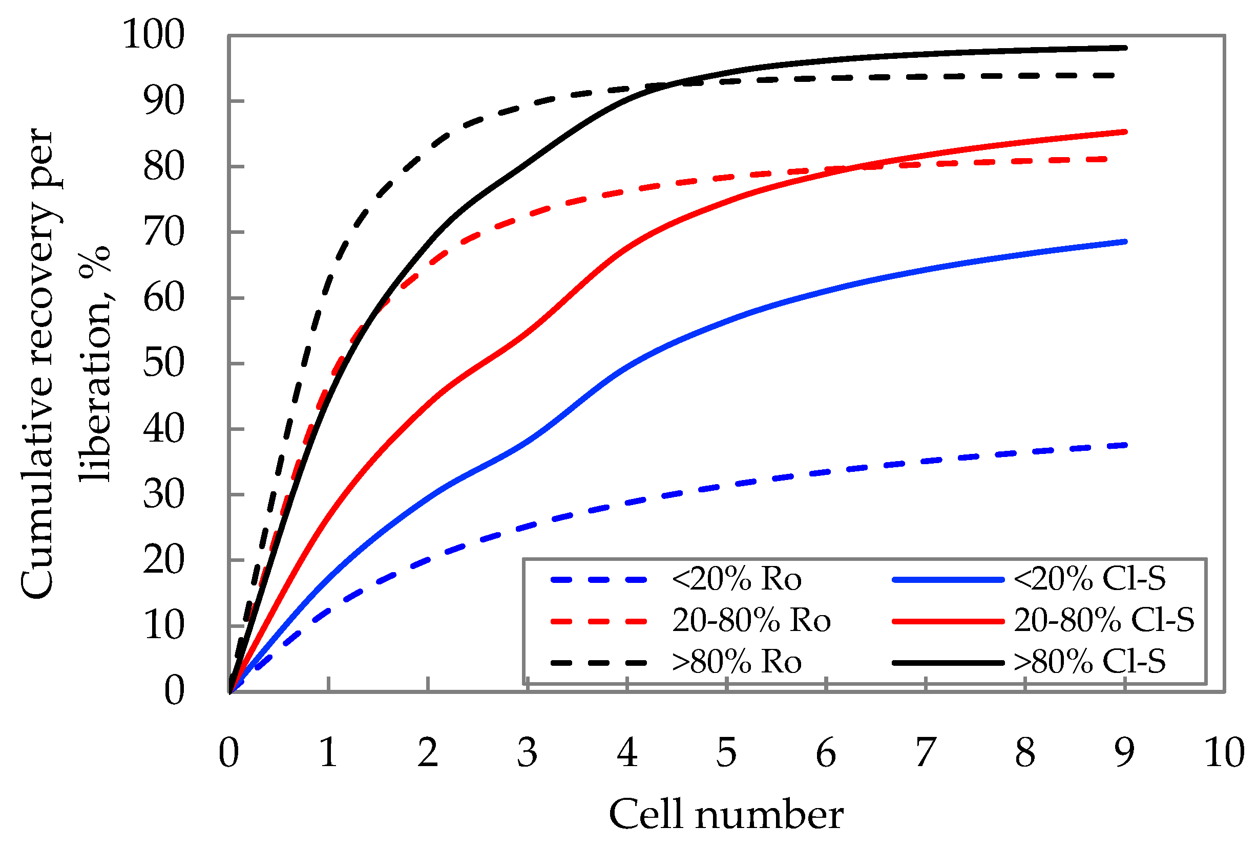
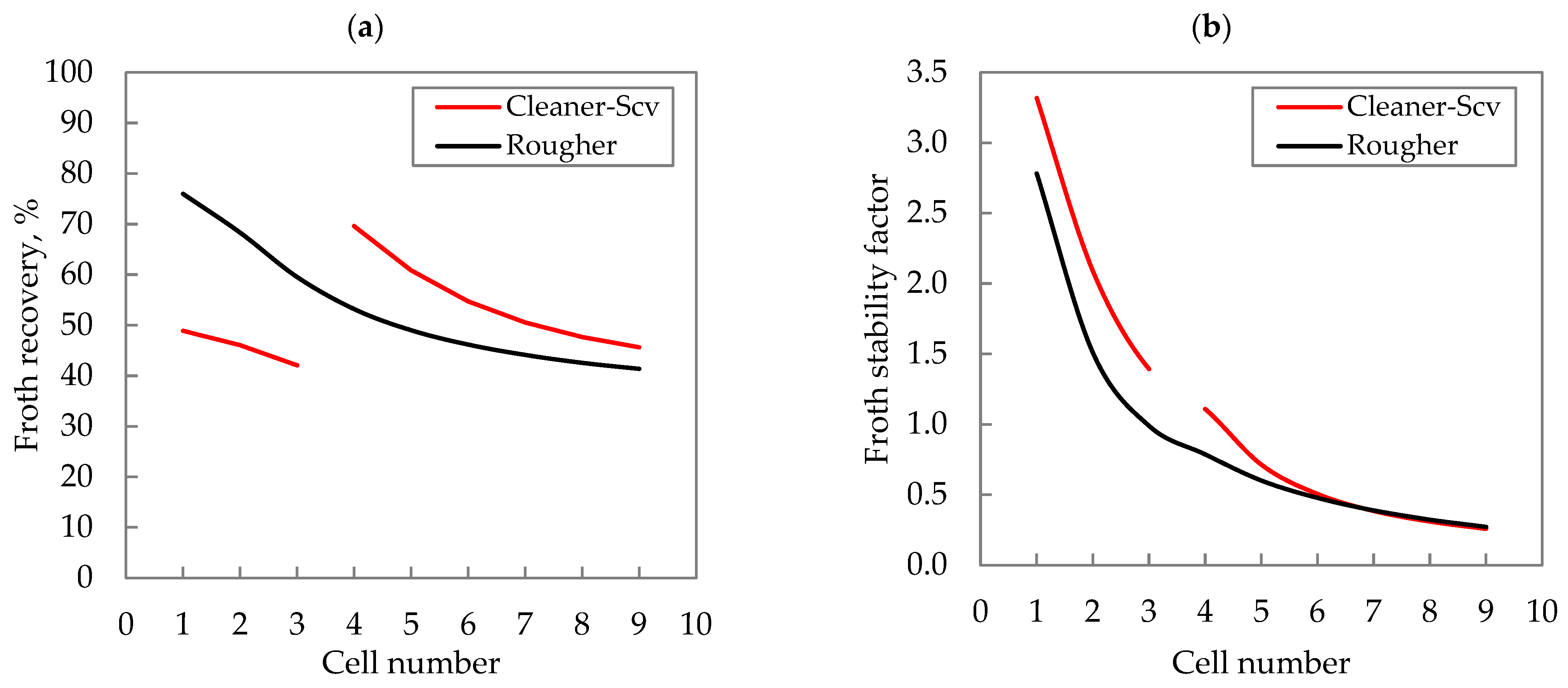
This paper presents the kinetic characterization per particle size classes and liberation of a first cleaner stage operating with a scavenger stage to produce the final tailings of the cleaner circuit. This information contributes to a better understanding of a typical cleaner–scavenger flotation operation, where the finer particle sizes improve the mineral liberation and the potential for the concentrate upgrade in the cleaner stage, while the scavenger stage mainly recovers the minerals which are not liberated enough and are recycled back to regrinding. The effects of main variables such as froth recovery, bubble loading, froth stability, gangue entrainment, and concentrate grade were compared with the results of the same flotation bank operating in the rougher stage.
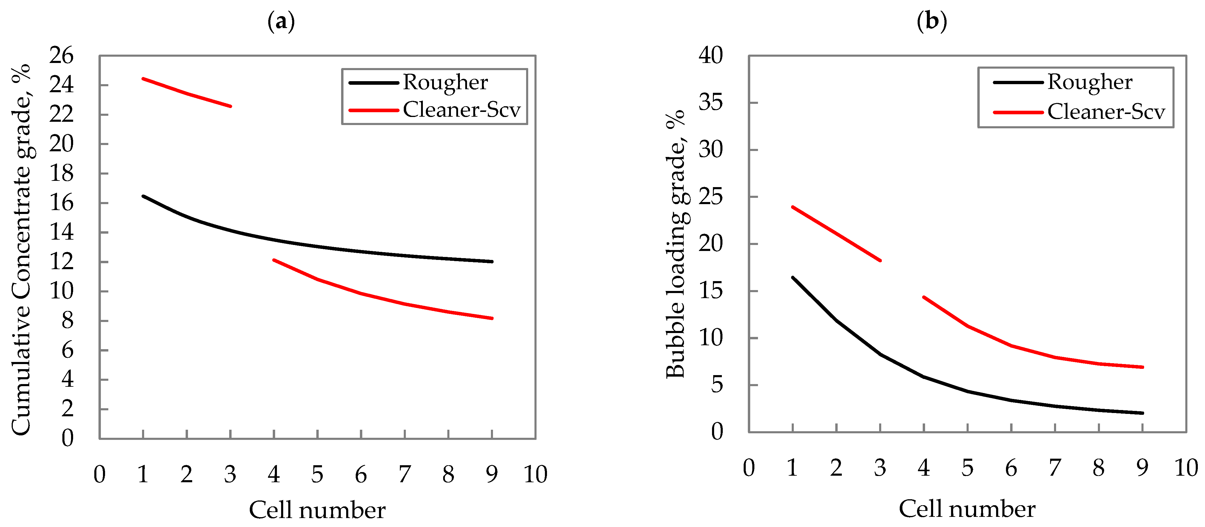
These variables can be significantly different in flotation banks, depending on the role that they develop in the flotation plant (e.g., rougher, and first cleaner stages). For instance, bubble loading is related to the floatable mineral mass that is transported by true flotation (as a bubble–particle aggregate) from the pulp to the froth zone in a flotation machine [7]. Thus, the mineral collected by true flotation in a cleaner cell has a higher grade and higher liberation (because of regrinding) than in a rougher one, resulting in faster kinetics. On the other hand, a proportion of the particles entering the froth by true flotation are returned to the collection zone because of the froth action that results in froth recovery. The froth recovery is defined as the ratio between the mass flowrate of floatable minerals recovered into the concentrate by true flotation and the mass flowrate of minerals entering the froth as particle–bubble aggregate (true flotation) [7,8,9]. The froth recovery has been commonly described as a simple function of time, but it depends on different factors such as cell design, froth transport distances, froth residence time, and froth stability. The latter is a key driver of flotation selectivity and recovery and is typically estimated as a factor proportional to the specific mass flowrate of collected mineral entering the froth (tph/m2) [10].
In this paper, a study of an industrial cleaner–scavenger stage was carried out, together with the analysis of the same circuit operating as a rougher stage (previous operation). Plant kinetics surveys were carried out in the current cleaner–scavenger circuit and when it was operating as a rougher bank, which allowed for obtaining the metallurgical performance and minerals characteristics in the streams for each case. Thus, the cleaner–scavenger operation was compared with the rougher operation. Additionally, an industrial simulation tool was used to characterize the cleaner–scavenger and rougher banks, allowing for estimating and comparing variables that are not commonly obtained from sampling surveys, such as froth recovery, gangue entrainment flowrate, water recovery, bubble loading grade, and others. The results from the sampling surveys were used to calibrate the simulation tool and characterize each stage.

2. Methodology

2.1. Sampling Surveys in the Cleaner–Scavenger Bank

Sampling surveys were carried out to characterize the metallurgical performance of the cleaner–scavenger circuit at the Cu concentrator of Doña Inés de Collahuasi mining company (CMDIC), which is located on the high plateau of the Atacama Desert, Chile, at 4.400 masl. Some streams of the flotation banks were sampled and then submitted for chemical analysis. Additionally, mineralogical and particle size information was provided to complement the study. 
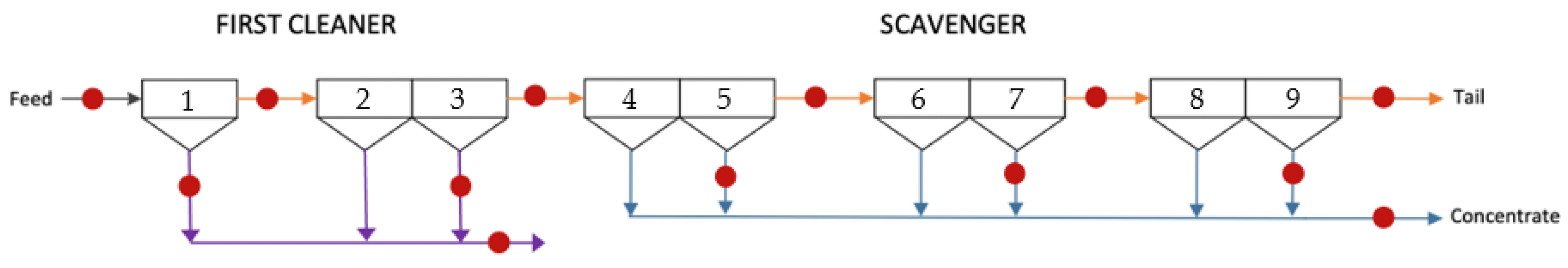
Figure 1 shows one of the cleaner–scavenger banks of the CMDIC concentrator (5 banks in total), which will be analysed in this study and consists of nine forced-air cells of 160 m3. The first three cells correspond to the first cleaner stage, and the next six cells belong to the scavenger stage. Figure 1 also includes the sampling points (red circles) in feed, concentrate, and tail streams, which allows for the characterization of the metallurgical performance along the bank after a mass balance data reconciliation. These samples were collected and analysed by personnel of CMDIC, using either manual or automatic samplers, depending on the sampling point.
The feed flowrate during the sampling surveys was around 300 t/h, with a Cu grade of 8.7%, P80 of 55 µm, and a solid content of 15%. With respect to the operating conditions, the first cleaner stage had a more selective operation, with froth heights of around 50 cm and superficial gas flowrates of 0.9 cm/s (at the froth surface). On the other hand, the scavenger stage showed a less selective operation, with froth heights of around 15 cm and superficial gas flowrates of 1.5 cm/s (at the froth surface).
This cleaner–scavenger bank was previously operated as a rougher bank until a few years ago, which was also characterized.
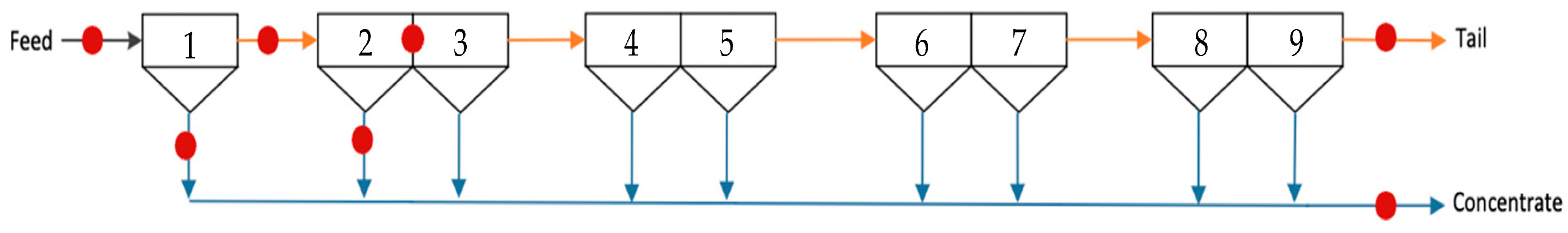
Figure 2 shows the rougher bank of the CMDIC concentrator with the sampling points (red circles) for metallurgical characterization after mass balance data reconciliation. This bank corresponds to the same one shown in Figure 1, but when it operated as a rougher bank. In this case, the short-cut method [11,12] was used to characterize the kinetics behaviour along the bank, which consisted of sampling the feed, concentrate, and tail from the first and second cells, in addition to the final tail and cumulative concentrate of the rougher bank. These samples were collected using manual or automatic samplers, depending on the sampling point.
The mineral fed to the bank when it was operating in the rougher stage had the following characteristics: flowrate of 1375 t/h, with a Cu grade of 1.2%, P80 of 200 µm, and a solid content of 34%. The operating conditions were froth heights of around 20 cm and superficial gas flowrates of 1.0 cm/s (at the froth surface).
Now, this study compares the flotation bank operation in the rougher and in the current cleaner–scavenger stages.

2.2. Metallurgical Prediction by Using an Industrial Simulation Tool

An industrial simulation tool was used to characterize the cleaner–scavenger bank, estimating variables that are not commonly obtained from sampling surveys, such as froth recovery, gangue entrainment flowrate, water recovery, bubble loading grade, and others. The metallurgical results from the sampling surveys in the cleaner–scavenger bank, as well as data from the bank operating as a rougher circuit, were used to calibrate the simulation tool and characterize each stage. This allowed for observing the differences between both operations based on internal variables of the process.
The simulation tool used in this study was built from a wide industrial database, which includes metallurgical performances and hydrodynamic and mineralogical data obtained from sampling campaigns performed in many concentrators in Chile for more than 20 years.
The simulation tool considers the sequential calculation of each single cell in the series, and the collection and froth zones are characterized independently using the two-zone model [8]. The collection zone was modelled based on actual residence time distributions measured at industrial circuits using the radioactive tracer technique [13]. On the other hand, the froth recovery is modelled as a function of froth stability, which depends on the solid flowrate entering the froth by true flotation; launder design, considering the froth transport behaviour; froth residence time; and particle size. This model was built and calibrated using a wide database on froth recoveries, measured at different industrial plants, with values from 40% to 90%. Results of froth recoveries per particle size class were also available from measurements in industrial plants.
The feed minerals, as well as the collection kinetics parameters, are characterized in terms of size-by-liberation classes.
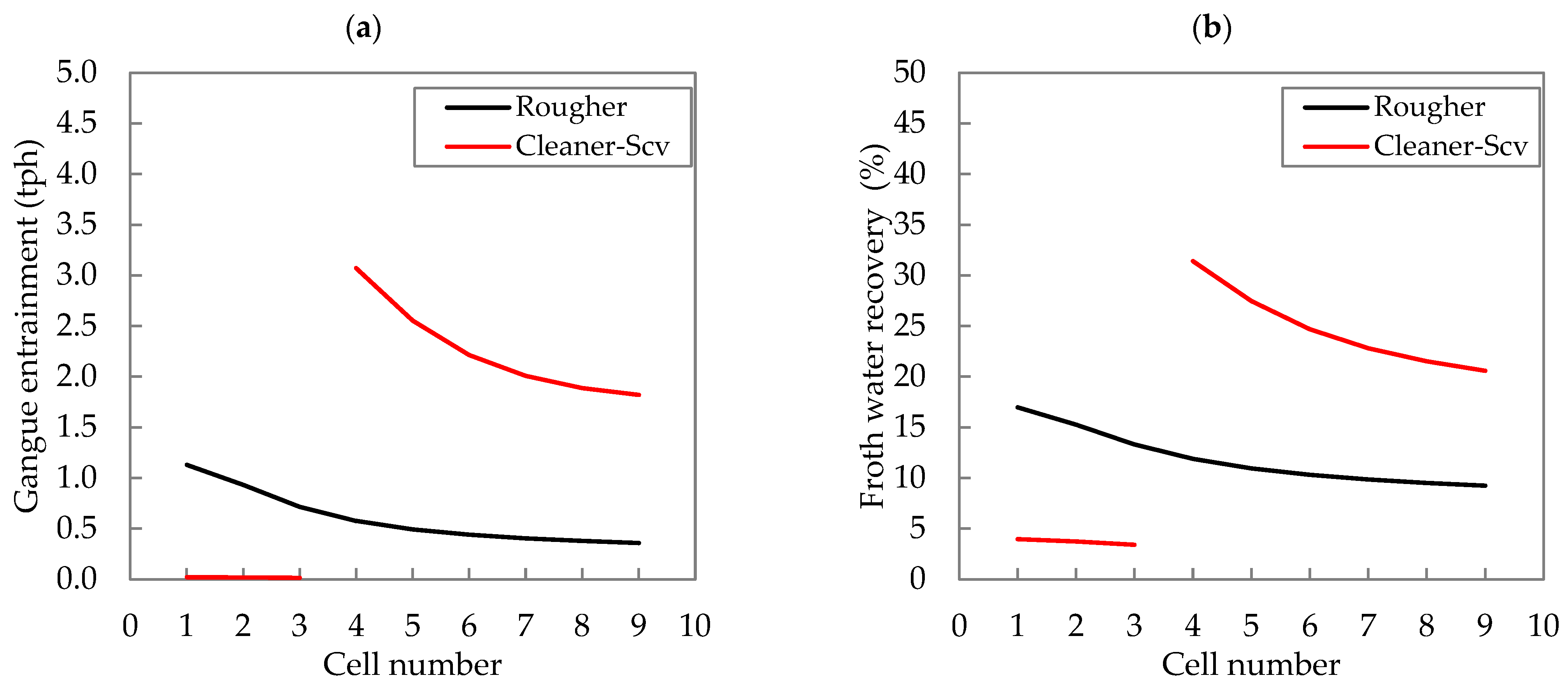
This simulation tool also includes a characterization of gangue entrainment, which is estimated from water recovery and particle settling velocity [14] in each cell. The froth water recovery was represented as a function of the solid froth recovery, froth depth, and air flowrate.
A more detailed description of this simulation tool was developed by Yianatos et al. [15]. Additionally, calibration and testing studies of the simulation tool have been reported [16,17,18,19]. This tool is currently implemented in the HSC Chemistry® software [20].

3. Results and Discussion

3.1. Calibration of the Simulation Tool from Industrial Data

The simulation tool was calibrated using the data from the sampling surveys, the feed characteristics, the cell design, and the operating conditions. Thus, the kinetics parameters size-by-liberation were obtained, fitting the recovery and concentrate grade profiles by using the least squares method.
Figure 3 shows the recovery and concentrate grade profiles along the cleaner–scavenger bank, including measured (red and blue points) and modelled data (black line). A good agreement between the measured and modelled data was observed.
It should be mentioned that a good agreement between measured and modelled data was also obtained when the simulation tool was calibrated for the bank operating as a rougher circuit.

3.2. Characterization of the Cleaner–Scavenger Bank

Figure 4 shows the cumulative recovery (Figure 4a) and the cumulative concentrate grade (Figure 4b) profiles, simulated per particle size class along the cleaner–scavenger bank. The coarse, intermediate, and fine classes correspond to >75 µm, 38–75 µm, and <38 µm, respectively.
Figure 4a shows that fine and intermediate particles are well recovered along the circuit, with a similar final recovery at the end of the scavenger stage. However, the coarser particles (>75 µm) show slow kinetics in the first cleaner stage, which operates in a more selective way, but they are better recovered in the scavenger stage, with a less selective operation. Thus, the first cleaner mainly rejects the coarser particles, but they are recovered in the scavenger bank to be sent to the regrinding stage.
Figure 4b shows that the selective operation in the first cleaner stage allows for reducing the gangue entrainment of fine particles, reaching the highest concentrate grades. However, the less selective scavenger operation causes a higher gangue entrainment of fine particles (<38 µm) and intermediate particles (38–75 µm), so the coarser particles reach higher concentrate grades in this stage.

3.3. Comparison of the Flotation Bank Operating as a Rougher or a Cleaner–Scavenger Stage

The metallurgical performance of the cleaner–scavenger bank was compared with that when the bank was operating at a rougher stage. Thus, the comparison includes aspects related to the Cu recovery and Cu concentrate grade.

3.3.1. Comparison of Cu Recovery

Figure 5 shows the Cu recovery profiles simulated per liberation class for the bank operating as the current cleaner–scavenger stage and the previous rougher stage (dashed lines). It must be noticed that 93% of the Cu sulphides fed to the 1° cleaner have liberation higher than 85%. Then, 4.5% of them have liberation between 20% and 80%, and 2.5% is occluded (liberation lower than 20%). The feed stream to the Scavenger stage (tail of cell 3) is composed of 84% of Cu sulphides liberated (>80% liberation), 9% middling (20%–80% liberation), and 7% occluded (liberation < 20%).
On the other hand, the feed stream to the circuit, when it was operating as a rougher stage, was composed of 86% Cu sulphides liberated, 5% middling, and 9% occluded. The liberation characteristics of the rougher feed were similar to those of the Scavenger feed. However, particle size in the feed is different in these two operations.
The results from Figure 5 show that the recovery of liberated and middling particles (>20% liberation) in the first cleaner stage is lower than in the rougher stage. However, the recovery significantly increases throughout the scavenger stage, resulting in a higher final recovery. On the other hand, for the occluded particles (<20% liberation), the recovery in the first cleaner stage is higher than in the rougher stage, mainly because this liberation class in the rougher stage contains coarser particles, which are more difficult to be recovered in the first cells of flotation banks.
Figure 6 shows the simulated froth recovery (Figure 6a) and the froth stability factor (from the froth recovery model in the simulation tool, Figure 6b) in each cell along the cleaner–scavenger and rougher banks.
Figure 6a shows that froth recovery is low in the first cleaner stage because of the more selective operation (high froth heights, 50 cm, and low superficial gas flowrate, 0.9 cm/s at the froth surface). However, the scavenger stage shows higher froth recoveries because of the less selective operation (low froth heights, 15 cm, and high superficial gas flowrate, 1.5 cm/s at the froth surface). The froth recoveries in the rougher stage are lower than those in the scavenger stage but higher than those in the cleaner stage. This is related to the operating conditions of the rougher stage and the froth mineralization degree that gives the froth stability, which is lower in the rougher stage because of the lower amount of collected minerals (Figure 6b). It should be mentioned that the froth stability, and therefore, the froth recovery, decreases along the banks for all cases because of the depletion of the valuable mineral, which decreases the collected mineral grade and the froth mineralization degree towards the end of the bank.

3.3.2. Comparison of Cu Concentrate Grade

Figure 7 shows the cumulative concentrate Cu grade (Figure 7a) and the bubble loading Cu grade profiles (Figure 7b), simulated along the cleaner–scavenger bank and the rougher bank.
Figure 7a shows that the first cleaner stage reaches the highest grades because of the selective operation. Then, the scavenger stage shows the lowest grades, while the circuit operating in a rougher stage shows intermediate values.
With respect to the bubble loading grade, Figure 7b, the first cleaner and scavenger stages show grades higher than those in the rougher stage because of the better quality of the mineral fed to these cleaning stages. In the first cleaner, the large differences in concentrate grades with respect to the scavenger and rougher stages are due to the cleaning action of the froth (high froth heights and low gas flowrates) in the first cleaner cells.
Figure 8 shows the gangue entrainment flowrate (Figure 8a) and the froth water recovery (Figure 8b) along the flotation bank, operating in the cleaner–scavenger and rougher stage.
Figure 8a shows that the first cleaner can reject most of the gangue entering the froth because of the high froth heights (50 cm). On the other hand, the scavenger stage shows higher gangue entrainment flowrates than those in the rougher stage because of the less selective operation, the more mineralized froths (better froth stability), and the better froth recoveries.
Figure 8b shows that the froth water recovery follows similar trends as the gangue entrainment because the water recovered into the concentrate transports the fine non-valuable particles that are recovered by entrainment.

4. Conclusions

The simulation tool allowed for studying internal variables along the cleaner–scavenger circuit, which are not easy to obtain from sampling surveys. Additionally, this tool allowed for comparing the metallurgical results and internal variables of the flotation bank operating as a cleaner–scavenger bank (current operation) and as a rougher bank (previous operation).
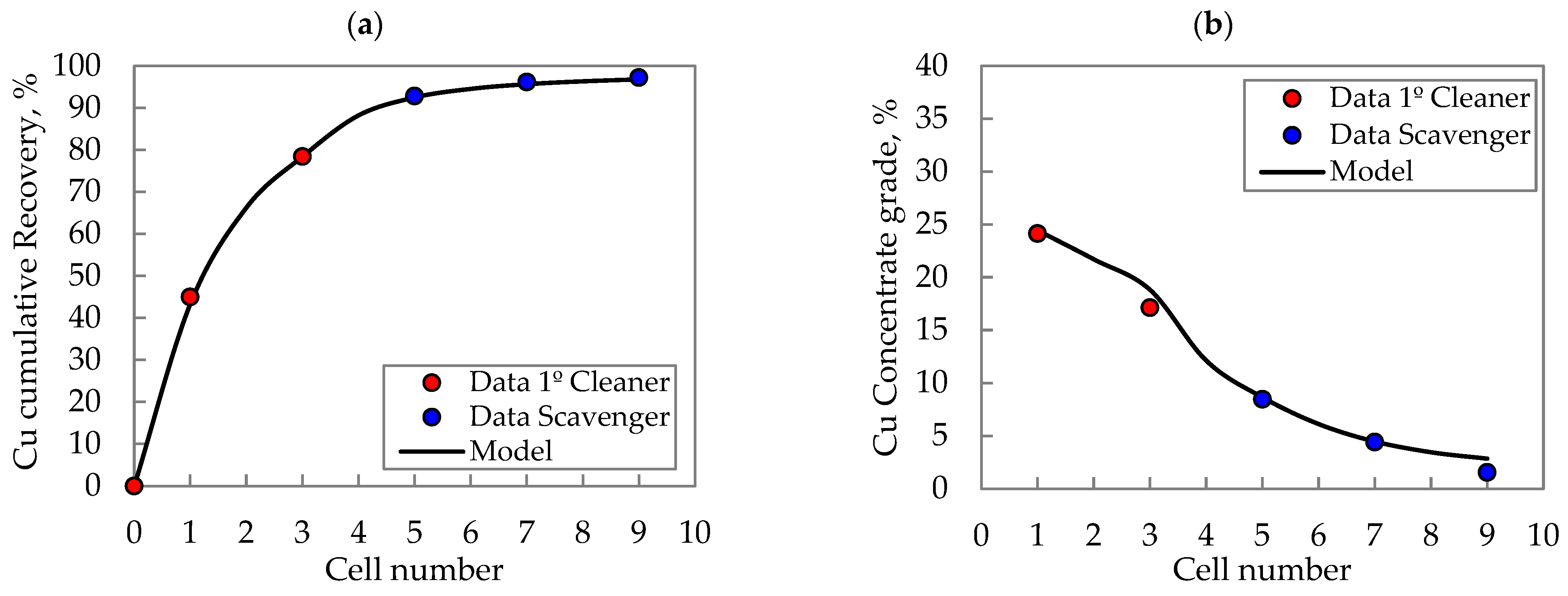
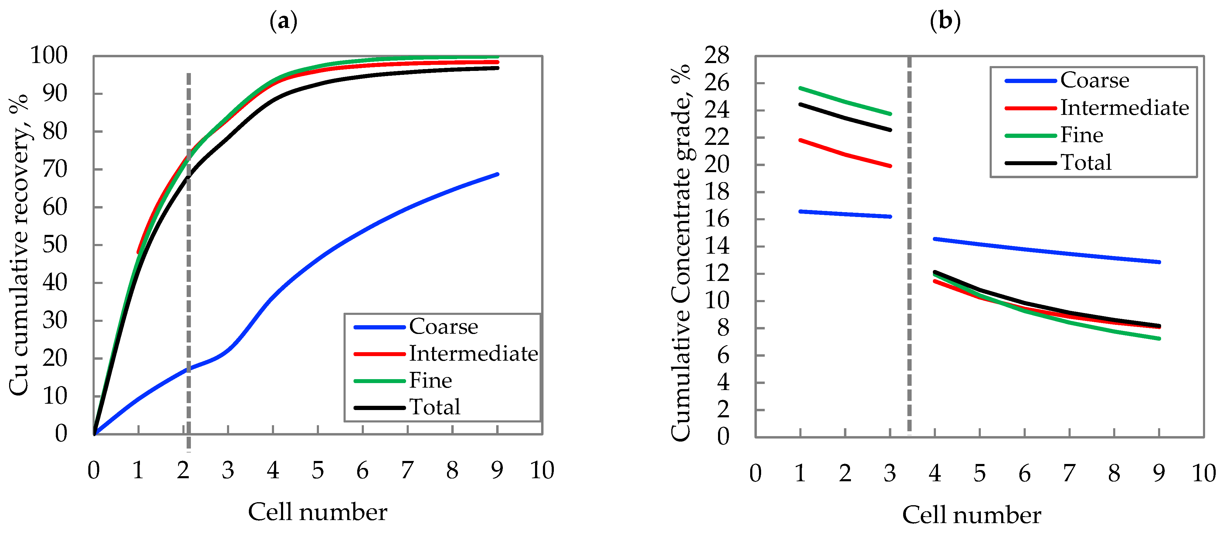
The results showed that the first cleaner operates in a selective way, so it rejects the coarser particles, but they are recovered in the scavenger bank (less selective operation) to be sent to the regrinding stage.
When comparing the cleaner–scavenger and rougher operations, it was found that the operating conditions and the froth mineralization degree that gives the froth stability caused significant differences in froth recovery in the different stages. Thus, the lowest froth recoveries were observed in the first cleaner stage, because of the more selective operation, with higher froth depths, despite the higher froth stability. The highest froth recoveries were found in the scavenger stage, because of the less selective operation and better froth stability, with respect to the rougher operation.
The concentrate grades in the first cleaner stage were significantly higher than those in the scavenger and rougher stages due to the cleaning action of the froth in these cells, which can reject most of the water and entrained gangue entering the froth. The scavenger stage showed higher gangue entrainment flowrates than those in the rougher stage because of the less selective operation, the most mineralized froths (better froth stability), and the better froth recoveries.
The first cleaner and scavenger stages showed higher bubble loading Cu grades than those in the rougher stage because of the better quality of the mineral fed to these cleaning stages.

Author Contributions

Conceptualization, P.V. and J.Y.; methodology, P.V., J.Y. and J.C.; software, P.V.; validation, J.Y., P.V. and M.R.; formal analysis, P.V.; investigation, J.Y. and P.V.; resources, M.R. and J.C.; data curation, P.V., J.Y. and J.C.; writing—original draft preparation, P.V. and J.Y.; writing—review and editing, P.V., M.R. and J.C.; visualization, J.Y.; supervision, J.Y. and M.R.; project administration, J.Y. and M.R.; funding acquisition, J.Y. and M.R. All authors have read and agreed to the published version of the manuscript.

Funding

This research was funded by Agencia Nacional de Investigación y Desarrollo (ANID), Fondecyt Project 1201335.

Data Availability Statement

The data presented in this study are available on request from the corresponding author. The data are not publicly available due to confidentiality restrictions.

Acknowledgments

The authors are grateful to Agencia Nacional de Investigación y Desarrollo (ANID), FONDECYT Project 1201335, and Universidad Técnica Federico Santa María, Chile, for providing funding for process modelling and control research. Additionally, we would like to thank Doña Inés de Collahuasi Mining Company, Chile, for allowing this collaborative work to be published.

Conflicts of Interest

The authors declare no conflict of interest. The funders had no role in the design of the study; in the collection, analyses, or interpretation of data; in the writing of the manuscript; or in the decision to publish the results.

References

  1. Wills, B.; Finch, J. Wills’ Mineral Processing Technology: An Introduction to the Practical Aspects of ore Treatment and Mineral Recovery, 8th ed.; Elsevier: Amsterdam, The Netherlands, 2016; pp. 351–366. [Google Scholar]
  2. Kupka, N.; Tolosana-Delgado, R.; Schach, E.; Bachmann, K.; Heinig, T.; Rudolph, M. R as an environment for data mining of process mineralogy data: A case study of an industrial rougher flotation bank. Miner. Eng. 2020, 146, 106111. [Google Scholar] [CrossRef]
  3. Yianatos, J.; Vallejos, P.; Rodríguez, M.; Cortínez, J. A scale-up approach for industrial flotation cells based on particle size and liberation data. Miner. Eng. 2022, 184, 107635. [Google Scholar] [CrossRef]
  4. Chen, X.; Peng, Y.; Bradshaw, D. The separation of chalcopyrite and chalcocite from pyrite in cleaner flotation after regrinding. Miner. Eng. 2014, 58, 64–72. [Google Scholar] [CrossRef]
  5. Chen, X.; Peng, Y.; Bradshaw, D. The effect of particle breakage mechanisms during regrinding on the subsequent cleaner flotation. Miner. Eng. 2014, 66–68, 157–164.
  6. Ni, C.; Xie, G.; Jin, M.; Peng, Y.; Xia, W. The difference in flotation kinetics of various size fractions of bituminous coal between rougher and cleaner flotation processes. Powder Technol. 2016, 292, 210–216. [Google Scholar] [CrossRef]
  7. Yianatos, J.B.; Moys, M.H.; Contreras, F.; Villanueva, A. Froth recovery of industrial flotation cells. Miner. Eng. 2008, 21, 817–825. [Google Scholar] [CrossRef]
  8. Finch, J.A.; Dobby, G.S. Column Flotation, 1st ed.; Pergamon: Oxford, UK, 1990. [Google Scholar]
  9. Rahman, R.M.; Ata, S.; Jameson, G.J. Froth recovery measurements in an industrial flotation cell. Miner. Eng. 2013, 53, 193–202. [Google Scholar] [CrossRef]
  10. Yang, S.; Wang, L. Measurement of froth zone and collection zone recoveries with various starch depressants in anionic flotation of hematite and quartz. Miner. Eng. 2019, 138, 31–42. [Google Scholar] [CrossRef]
  11. Yianatos, J.; Henríquez, F. Short-cut method for flotation rates modelling of industrial flotation banks. Miner. Eng. 2006, 19, 1336–1340. [Google Scholar] [CrossRef]
  12. Qaredaqi, M.; Haji Amin, H.; Abdollahi., H. Comparison of Yianatos and traditional methods to determine kinetic rate constants of different size fractions in industrial rougher cells. Int. J. Miner. Process. 2012, 106–109, 65–69. [Google Scholar] [CrossRef]
  13. Yianatos, J.; Bergh, L.; Vinnett, L.; Panire, I.; Díaz, F. Modelling of residence time distribution of liquid and solid in mechanical flotation cells. Miner. Eng. 2015, 78, 69–73. [Google Scholar] [CrossRef]
  14. Wang, L.; Runge, K.; Peng, Y.; Vos, C. An empirical model for the degree of entrainment in froth flotation based on particle size and density. Miner. Eng. 2016, 98, 187–193. [Google Scholar] [CrossRef]
  15. Yianatos, J.; Vallejos, P.; Grau, R.; Yañez, A. New approach for flotation process modelling and simulation. Miner. Eng. 2020, 156, 106482. [Google Scholar] [CrossRef]
  16. Vallejos, P.; Yianatos, J.; Grau, R.; Yañez, A. Evaluation of flotation circuits design using a novel approach. Miner. Eng. 2020, 158, 106591. [Google Scholar] [CrossRef]
  17. Vallejos, P.; Yianatos, J.; Grau, R.; Yañez, A. The Impact of Froth Launders Design in an Industrial Flotation Bank Using Novel Metallurgical and Hydrodynamic Models. Minerals 2023, 13, 169. [Google Scholar]
  18. Vallejos, P.; Yianatos, J.; Grau, R.; Yañez, A. Effect of Mineral Feed Characteristics on Industrial Flotation Circuits Performance by Simulating Mineralogical and Operational Changes; IMPC: Cape Town, Sudáfrica, 2020. [Google Scholar]
  19. Vallejos, P.; Yianatos, J.; Grau, R.; Yañez, A. Effect of cell arrangement and operating conditions on internal variables along industrial flotation banks. In Proceedings of the Flotation’21, London, UK, 8–12 November 2021. [Google Scholar]
  20. Metso Corporation. HSC Chemistry® Software. Available online: https://www.metso.com/portfolio/hsc-chemistry/?r=3> (accessed on 9 May 2023).
Figure 1. Cleaner–Scavenger flotation bank (9 cells of 160 m3) at CMDIC concentrator.
Minerals 13 00875 g001
Figure 2. Rougher flotation bank at CMDIC concentrator in the previous operation.
Minerals 13 00875 g002
Figure 3. Comparison of measured and modelled data: (a) Recovery and (b) Concentrate grade.
Minerals 13 00875 g003
Figure 4. (a) Recovery profiles and (b) Concentrate grade profiles, simulated per particle size class.
Minerals 13 00875 g004
Figure 5. Comparison of simulated recovery profiles per liberation class along the flotation bank as rougher (Ro) and cleaner–scavenger (Cl-S) stages.
Minerals 13 00875 g005
Figure 6. Comparison of the flotation bank as rougher and cleaner–scavenger stages: (a) Simulated froth recovery and (b) Froth stability factor.
Minerals 13 00875 g006
Figure 7. Comparison of (a) the concentrate Cu grade profile and (b) the bubble loading Cu grade profile, simulated along the bank as a rougher and cleaner–scavenger stage.
Minerals 13 00875 g007
Figure 8. Comparison of (a) simulated gangue entrainment and (b) simulated froth water recovery of the flotation bank as a rougher and cleaner–scavenger stage.
Minerals 13 00875 g008
Disclaimer/Publisher’s Note: The statements, opinions and data contained in all publications are solely those of the individual author(s) and contributor(s) and not of MDPI and/or the editor(s). MDPI and/or the editor(s) disclaim responsibility for any injury to people or property resulting from any ideas, methods, instructions or products referred to in the content.

