Article

Enhancing Fines Recovery by Hybrid Flotation Column and Mixed Collectors

by
Polyxeni K. Tsave
1,
Margaritis Kostoglou
1,
Thodoris D. Karapantsios
1 and
Nikolaos K. Lazaridis
2,*
1
Laboratory of Chemical and Environmental Technology, School of Chemistry, Aristotle University of Thessaloniki, GR-541 24 Thessaloniki, Greece
2
Division of Chemical Technology & Industrial Chemistry, School of Chemistry, Aristotle University of Thessaloniki, GR-541 24 Thessaloniki, Greece
*
Author to whom correspondence should be addressed.
Minerals 2023, 13(7), 849; https://doi.org/10.3390/min13070849
Submission received: 8 May 2023 / Revised: 18 June 2023 / Accepted: 19 June 2023 / Published: 23 June 2023
(This article belongs to the Special Issue Recent Advances in Flotation Process)

Abstract

:
The froth flotation technique can be considered one of the most efficient methods for the separation of minerals. Prior to utilizing any physicochemical separation method, the size of the mined ore must be decreased to facilitate the release of the valuable materials. This practice, along with the increased exploitation of ores that carry fine mineral particles caused the production of fine and ultrafine particles which are difficult to recover with classical enrichment methods, due to their different characteristics compared to coarser particles. It is established that fine and ultrafine particles are difficult to float, leading to losses of valuable minerals, mainly due to their low collision efficiency with bubbles. Moreover, fine particles require higher reagent consumption due to the fact that have a higher specific area, and finally, their flotation is limited by low kinetic energy. Flotation of fines can be enhanced by either decreasing bubble diameter or increasing their apparent size, or moreover, by enhancing the collector’s adsorption (their hydrophobic behavior) using alternative reagents (non-ionic co-collectors). In the present research, flotation experiments on a hybrid electrolytic flotation column that can produce microbubbles (−50 μm), were carried out for recovering fine magnesite (−25 μm) particles. In addition, the synergistic effect of anionic/non-ionic collectors were studied for the enhancement of fines recovery. Experimental flotation results so far designate the enhancement of fine magnesite particle recovery by approximately 8% with the addition of microbubbles. Finally, the synergistic effect of anionic/non-anionic collectors led to the improvement of flotation recovery by almost 12%.

1. Introduction

Froth flotation is one of the most important technological achievements of the 20th century. It is the most widespread mineral beneficiation method and has contributed with great efficiency to the raw materials industry [1]. Flotation is a separation technique based on the differences in surface wettability of materials. When air is inserted in an aqueous dispersion of a mineral mixture only the hydrophobic particles attach to bubbles and rise to the top where they are recovered, while the hydrophilic particles sink. Given that the most of the minerals are hydrophilic by nature, surfactants called collectors are added to selectively adsorb on the targeted minerals and increase their hydrophobicity [2]. The improvement of flotation efficiency necessitates the simultaneous adjustment of several variables related to the surface properties of mineral particles, chemical processes of the pulp, and hydrodynamic conditions in the flotation cell. The simultaneous enhancement of the three main flotation process components-operational, chemical, and equipment-makes it feasible to improve the flotation efficiency of complicated ores [3].
As earlier defined by Gaudin et al., the method is particularly successful when applied to a particle size range of approximately 15–150 µm [4]. In this primary work, the well-known “Elephant Curve” illustrates the clear decrease in flotation performance outside of this size range. This behavior, regarding the larger particles, is mainly attributed to turbulence and the inability of buoyancy to drive them to the froth phase [5,6]. On the contrary, the main reason for the low flotation efficiency of fine particles lies in the low collision efficiency with conventionally sized bubbles [7,8,9,10]. Fine particles show different behavior compared to coarser particles and their main characteristics are: (1) higher surface area per unit mass (higher collector consumption), (2) tendency to follow the fluid flow around a bubble more easily than a larger particle (greater entrainment tendency), (3) slower flotation rate and (4) more susceptible to the chemistry of the pulp and to the ions contained in this [5]. Recent advancements have been developed which aim to increase the bubble-particle collision efficiency, either by reducing the bubble size [11,12,13,14] or by increasing the apparent particle size [15,16]. However, both approaches are practically difficult to implement on an industrial scale. The former needs selective flocculation of fine particles [17], which is not always possible [18] and the latter needs bubbles sized <50 µm, whose production and industrial use are quite demanding processes [15]. However, on a laboratory scale the use of microbubbles (<100 µm, produced by electroflotation, hydrodynamic cavitation or gas supersaturation) appears to be a relatively more efficient process with selectivity which increases the collision efficiency of fine and ultrafine particles with these bubbles and consequently increase the flotation recovery and rate [19,20]. Another alternative method to improve fines recovery is by means of using a carrier material [21,22,23] i.e., a material that can selectively collect fine hydrophobic materials so that the relative size of the fines is increased. Flotation recovery can be also increased with the addition of nonionic reagents or other additives to enhance the selective adsorption of the main collector or, finally, through recently technological innovations regarding the design of flotation cells [16,17,18].
Fine particles mainly derive from the fractionation in an effort to release the useful minerals from the sterile ones or from the increased exploitation of ores with lower quality or less pure streams. The impossibility of enriching and utilizing these fine particles which accumulate unexploited is economically detrimental to the industries and moreover a burden on the environment. Among some recent technological innovations is a version of a Jameson cell which promotes high mixing and intensive contact between air bubbles and mineral particles [19] increasing the probability of particle-bubble collision. In addition, the HydroFloatTM device uses an aerated dense fluidized-bed of particles where gas bubbles pass through the bed of particles [24] and the Stack Cell device incorporates a high-shear bubble-particle contactor, specially designed to efficiently channel energy for the collision of bubbles with particles [25]. The Concorde cell increases flotation recovery of particle sizes from 0 to 150 µm [19]. Lately, considerable attention has attracted the oscillating grid flotation cell (OGC) [2,26,27,28]. In addition, a flotation device using ultrasound has been developed which consists of a separation cell, a bubble de-aerator and an ultrasound transmitter placed inside the reactor [29]. Finally, a hybrid Denver type flotation device was developed by employing electrolysis units that produce microbubbles by our group [30].
Salt type (carbonate) minerals are recovered by flotation using an anionic surfactant as the main collector, such as sodium oleate. However, recovery could be increased with the addition of nonionic reagents or other additives to enhance the selective adsorption of the anionic collector. A recent study refers to the use of branched alcohols and/or their alkoxylates as secondary collectors for recovering salt type ores, in combination with a main collector (anionic or an amphoteric surface active compound) [31]. Non ionic collectors are adsorbed by forming hydrogen bonds and the adsorption capacity is affected by the ethoxylation degree. For example, non ionic surfactants with lower ethoxylation degree show preferential adsorption on silica compared with those with higher ethoxylation grade [32] due to the steric effect of the ethylene oxide chains on the hydrocarbon chain-chain interaction at the solid/liquid interface. The hydrophobicity of a mineral surface after surfactant adsorption has been found to be dependent on the structure of surfactant, as well as the adsorption density. These changes in hydrophobicity are interpreted by considering changes in the orientation of the hydrocarbon chain of the adsorbed surfactant [32].
Based on the aforementioned information it is assumed that either the combined use of conventional and microbubbles or the synergistic effect of anionic/non-ionic collectors may increase the flotation of fine magnesite particles. The innovation of this study relies on the construction of a hybrid flotation column that generates in situ microbubbles, by employing electrolysis of water, and the use of non-ionic surfactants for improvement of fine magnesite particle flotation. In the current study, a two-stage flotation process is proposed, which is a combination of conventional flotation and electroflotation and the synergistic use of sodium oleate and non-ionic co-collectors. It is believed that employing electrolysis for micro-bubble generation in support of fine particle flotation enhancement will be used economically, even on an industrial scale, by employing alternative energy resources from renewable processes, e.g., solar power. Therefore, research must continue on a larger scale.

2. Materials and Methods

The present study was conducted by employing magnesite samples (−25, −45, −100 μm) provided by the Grecian Magnesite Company located in Northern Greece. The main collector used in this research was the anionic surfactant sodium oleate (NaOl, ≥82% fatty acids, Riedel-de Haen). In addition, the non-ionic co-collectors studied (ethoxylated and alkoxylated alcohols) were Dodecyl Alkoxylate 54, Dodecyl Ethoxylate 3, Isotridecyl Alkoxylate 52, Isotridecyl Ethoxylate 3 and Isotridecyl Ethoxylate 10, provided by BASF. The pH was adjusted using 0.1 M NaOH/HCl (Pancreac) and moreover, pine oil was employed as afrother to improve the stability of the froth, while promoting the flotation process [33]. Sodium chloride (NaCl, VWR Chemicals) was utilized as a background electrolyte, and throughout the flotation experiments deionized (~10 μS/cm) water was used.

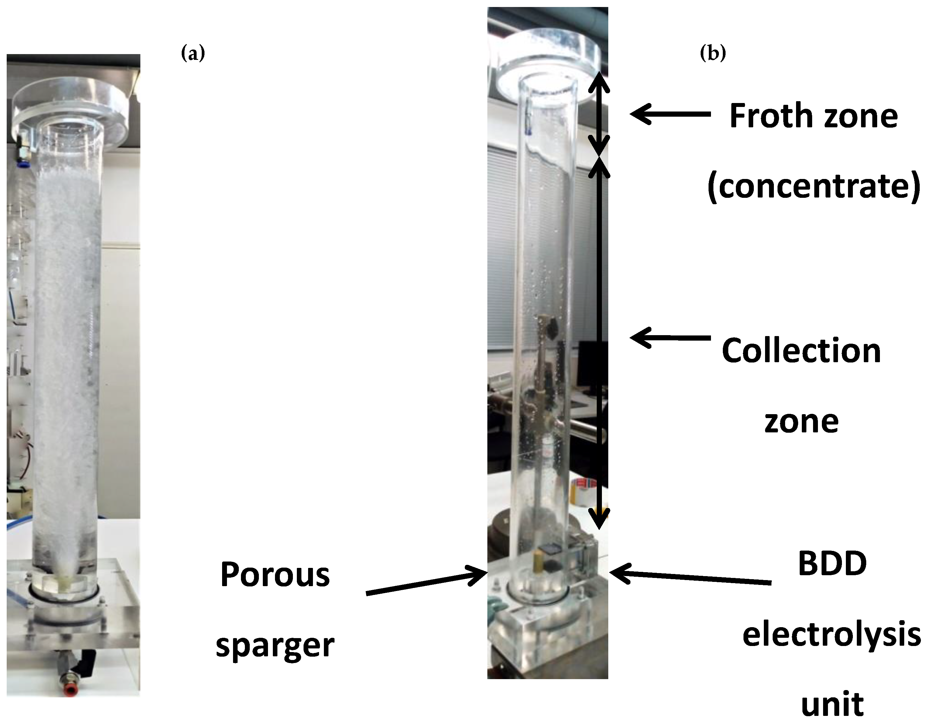
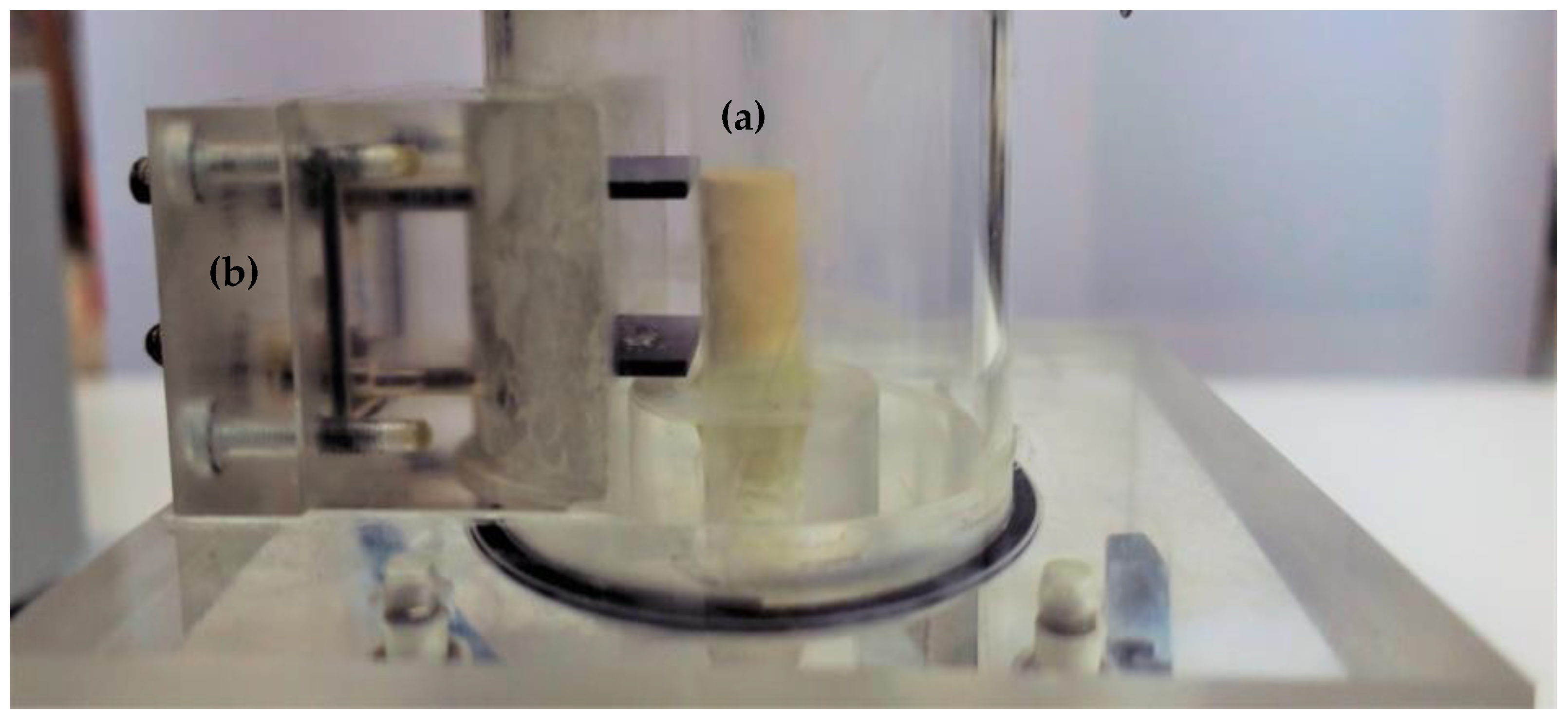
2.1. Experimental Set up-The Hybrid Flotation Column

The laboratory flotation device used for mineral flotation in the present study is a laboratory-scale custom manufactured column (Scheme 1a). The flotation column consists of three plexiglass cylindrical sections, connected with two flanges and it is completely sealed. Plexiglas is a preferential material used for laboratory scale flotation columns mainly due to its stability and moreover, it serves for the three-phase flow observation. The column height is 60 cm, its diameter is 7 cm, and the wall thickness is 3 mm. At the top of the flotation column, around the outer surface, a concentric cylindrical overflow weir is mounted where the recovered particles are collected. The column can be divided into two zones (Scheme 1b): the collection zone, where particles collide with the air bubbles and the froth zone, where the recovered particles are collected.
Two Boron Doped Diamond (BDD) electrodes serve as an electrolysis unit, as described in a previous study [30]. The electrodes were placed horizontally and parallel and the unit is supported on the inner wall of the flotation column 6 cm above the bottom of the columns (Scheme 2), so that the produced microbubbles can be dispersed homogeneously in the column’s volume. The electrolysis unit is connected to an external power supply. There is a large number of studies indicating that combining conventional-sized bubbles with microbubbles leads to the enhancement of fine particle recovery [34,35,36]. The hybrid column is capable of producing bubbles anwith average bubble diameter of less than 40 and over 400 µm. The resulting hybrid flotation column is called BBD-Hybrid Column (BDDHC, Boron Doped Diamond Hybrid Column) and is capable of producing bubbles with different bubble size diameters enhancing the flotation of fine mineral particles.

2.2. Flotation Experiments

The flotation experiments were realized in the hybrid column, where no agitation is carried out (absence of mechanical parts and an impeller), with the use of an aeration system (ceramic porous sparger/ microbubble generator) in the slurry. Initially, in a 2000 mL beaker, 1750 mL of deionized water was added with 17.5 g of the mineral and the desired concentration of the collector. At this stage, when the synergistic effect between anionic and non-ionic collectors was examined, the co-collector was also added. pH was adjusted to the values of interest using NaOH and HCl. Continuous stirring was performed for 5 min [30] at a rate of 500 rpm. At this time, conditioning of the hydrophilic particles took place. The preferred concentration of the frother was added and stirring continued for an additional minute. The suspension was then transferred to the flotation column. During the experiments performed in the presence of microbubbles, conditioning of fine magnesite particles with microbubbles was conducted (20 min) after conditioning with the collector/co-collector and prior to the induction of dispersed (coarse) bubbles. Experiments were performed at room temperature (RT; ~20–25 °C).
The dispersion of air in the column was carried out through a ceramic sparger, located at the bottom of the column with an average pore diameter of 10–16 μm. The airflow of conventional/coarse bubbles was adjusted by a calibrated flowmeter (0.7 L/min). Upon the flotation process completion (after 5 min), the recovered mineral particles were collected from the concentric cylindrical weir on the top of the column and were dried and weighed. The recovery of the mineral particles in the froth product (R) was computed as:
R% = 100 c/f
where, c: mass of concentrate, f: mass of feed.
Moreover, flotation experiments were performed in triplicate, and the values represent the mean value of independent experiments. The obtained data were presented as average and standard error mean (SEM) values of multiple sets of independent measurements. Recovery percentages and SEMs were calculated for each individual group.
Some of the recovered particles were analyzed regarding their size in order to ascertain the effect of microbubbles on the recovered particle’ size. The particle size analysis was conducted in wet sample dispersion (Malvern 2000). In the framework of flotation experiments kinetic studies have been performed in an effort to study the recovery rates with regard to (i) particle size and (ii) the presence of microbubbles. On this base, for both cases, concentrates were collected at 1–6 min of flotation time and the corresponding recoveries were calculated.
The experimental data deriving from the experiments represent the mean value of at least three single and independent experiments. Subsequently, the obtained data are presented as average and standard error mean (SEM) values of sets of independent measurements. Recovery percentages and SEMs are calculated for each individual group.
The effect of conditioning time (0–20 min) with microbubbles, pH (2–12), collector (0–120 mg/L), and electrolyte concentration (0–1 M), with regard to bubble size were investigated. Some of the flotation products were analyzed concerning their particle size distribution in an effort to define the contribution of the electrolytic bubbles to fine and ultrafine particle recovery. Moreover, the synergistic effect of nonionic-anionic surfactants on fine magnesite particles was examined as an alternative approach to enhance fines recovery.

3. Results

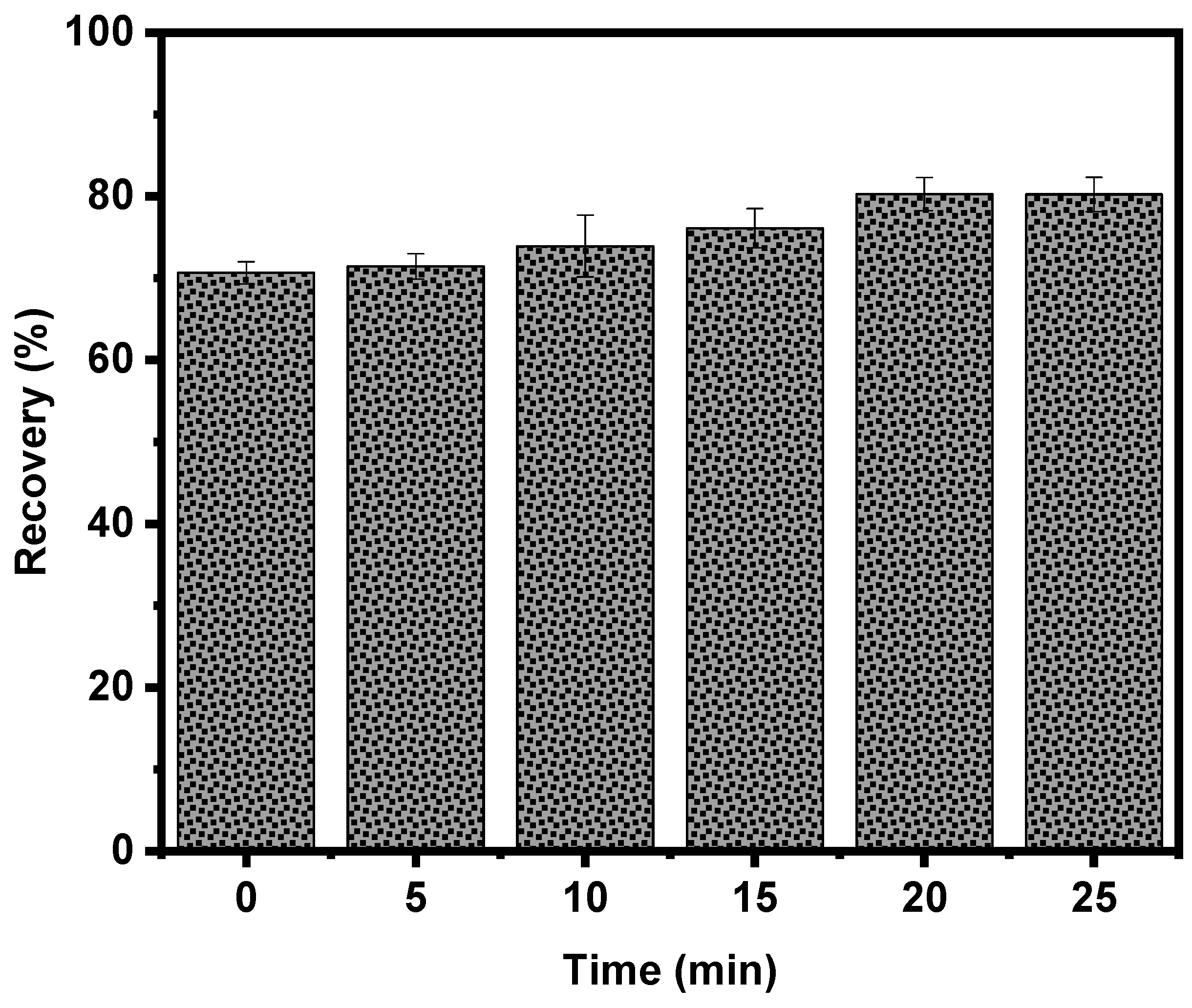
3.1. Effect of Conditioning Time with Electrolytic Bubbles

In order to examine the enhancement of fine and ultrafine magnesite particles (−25 µm) recovery flotation experiments were carried out in the hybrid flotation column. In these experiments, the effect of the presence of microbubbles (~45 μm) was studied. Initially, the treatment time of magnesite particles with microbubbles was investigated. Figure 1 illustrates the effect of the conditioning time of the mineral with microbubbles, produced by water electrolysis, once it has been treated with the collector and before introducing dispersed air (coarse) bubbles (~210 μm) into the slurry. The size of bubbles is determined by capturing bubble images using a high-resolution digital camera (a 20MP Canon EOS 70) equipped with macro lenses and extension tubes for efficient image magnification A custom-made image analysis software (BubbleSEdit software, Laboratory of Chemical and Environmental Technology, School of Chemistry, Thessaloniki) is used to automatically detect the bubbles contour and measure their size and consequently obtain the corresponding bubble size distributions [30]. The results show that the treatment of magnesite with electrolytic bubbles enhances the flotation recovery, and the maximum recovery is achieved when the treatment time reaches 20 min. Further conditioning does not improve recovery. It is considered that 20 min is the time required for the electrolytic bubbles to act as selective flocculants, promoting the formation of large aggregates, which are easier to float by dispersed-air bubbles. In particular, the recovery of magnesite particles in the absence of electrolytic bubbles is 70% and when magnesite is conditioned with microbubbles for 20 min the recovery reaches 81%.
The results indicate the importance of the presence of smaller bubbles in the enhancement of fine particle recovery. This is attributed, most likely, to the formation of hetero-aggregates (mineral particles and microbubbles) under the effect of electrostatic attraction between particles and microbubbles [37], which leads to the increase of the apparent minerals’ particle size. It is experimentally and theoretically clear that the flotation rate increases when particle size increases [7,14,38,39,40,41]. The hetero-aggregates formed can be floated more sufficiently by the coarser bubbles, due to the fact that particles with larger sizes exhibit higher collision efficiency with conventional bubbles.

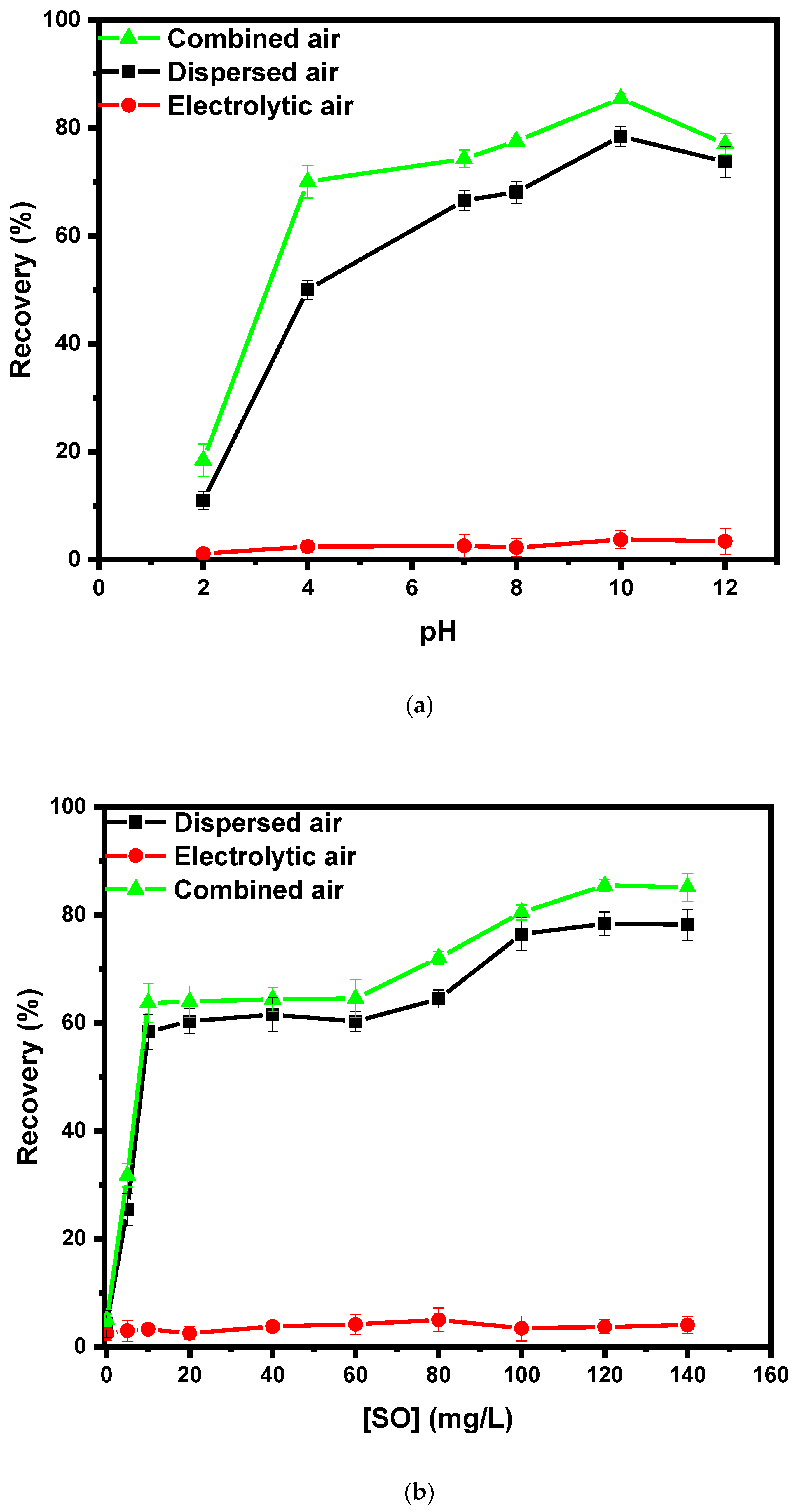
3.2. Effect of pH and Collector Concentration on Combined Magnesite Flotation

Figure 2a illustrates the effect of pH on the recovery of magnesite in the presence of sodium oleate as a collector with regards to (i) dispersed, (ii) electrolytic, and (iii) combined air. The pH values tested ranged from 2 to 12. The graph shows that for all three cases, the behavior along the pH values is similar; recovery of magnesite is very poor in acidic conditions and increases when the pulp pH value increases. The solubility of magnesite in acidic pH values cannot be excluded. When pH values are lower than 6 adsorption of sodium oleate (anionic collector) does not occur effectively, so flotation is not promoted at pH values due to the fact that the surface is positively charged. This is probably because adsorption of the collector on the magnesite surface occurs possibly through chemisorption. At pH 7–10 the recovery of magnesite in presence of dispersed air increased from 66.5 to 78.4% and from 74.2 to 85.4% when combined air is utilized. The recovery of magnesite increases significantly as the pH value increases, reaching the maximum value for pH 10, while further increase decreases recovery. The results are consistent with a previous study of magnesite flotation [42]. Adsorption of the collector on a magnesite surface is not favored in acidic conditions, so a very small percentage of particles recover [43]. Electrolytic bubbles alone cannot float magnesite particles.
The experimental findings indicate that the highest recovery is achieved in the presence of combined air. The results prove that the treatment of magnesite with microbubbles (20 min) enhances the recovery of fines leading to a recovery improvement of about 7%–8% when compared to recovery achieved in the presence of single dispersed air. Based on the literature, electrolytic bubbles act as ‘bridges’ increasing the apparent size of fine particles and thereby enhancing their flotation [44]. Rulyov et al. established the hetero-aggregation of fine particles with microbubbles in a non-uniform hydrodynamic field for a flotation cell [34]. More specifically, the microbubbles act as carriers of the fine particles, thus enabling their collision with the coarse bubbles. Therefore, flotation of particle-microbubble hetero-aggregates by conventional bubbles is more efficient than when using exclusively conventional-sized bubbles.
Figure 2b demonstrates the effect of collector concentration on fine magnesite particles in the presence of (i) dispersed air, (ii) electrolytic air, and (iii) combined air. Maximum recovery occurs at the concentration of sodium oleate 120 mg/L for all cases. With further increase of collector concentration, the recovery of magnesite was stable; therefore, 120 mg/L can be defined as the maximum collector dose. When sodium oleate concentration becomes 240 mg/L recovery decreases. This is due to the fact that an excess of collector concentration is able to create a new adsorption layer which renders the particles hydrophilic again, thus reducing the flotation efficiency [45]. In a previous study, Yin et al. studied the effect of sodium oleate on the recovery of magnesite fraction with grain size smaller than 74 µm and larger than 38 µm (+38–74 µm) [46]. The results showed that the optimal collector concentration was 90 mg/L and further increase of the concentration did not increase the recovery of the mineral [46]. The −25 μm magnesite particles fraction requires an increased amount of collector (120 mg/L), due to their larger specific surface [47]. In addition, it is evident that maximum recovery is achieved after treating magnesite particles with electrolytic microbubbles. In particular, the recovery increased by 8% compared to the experiments conducted exclusively with dispersed air.

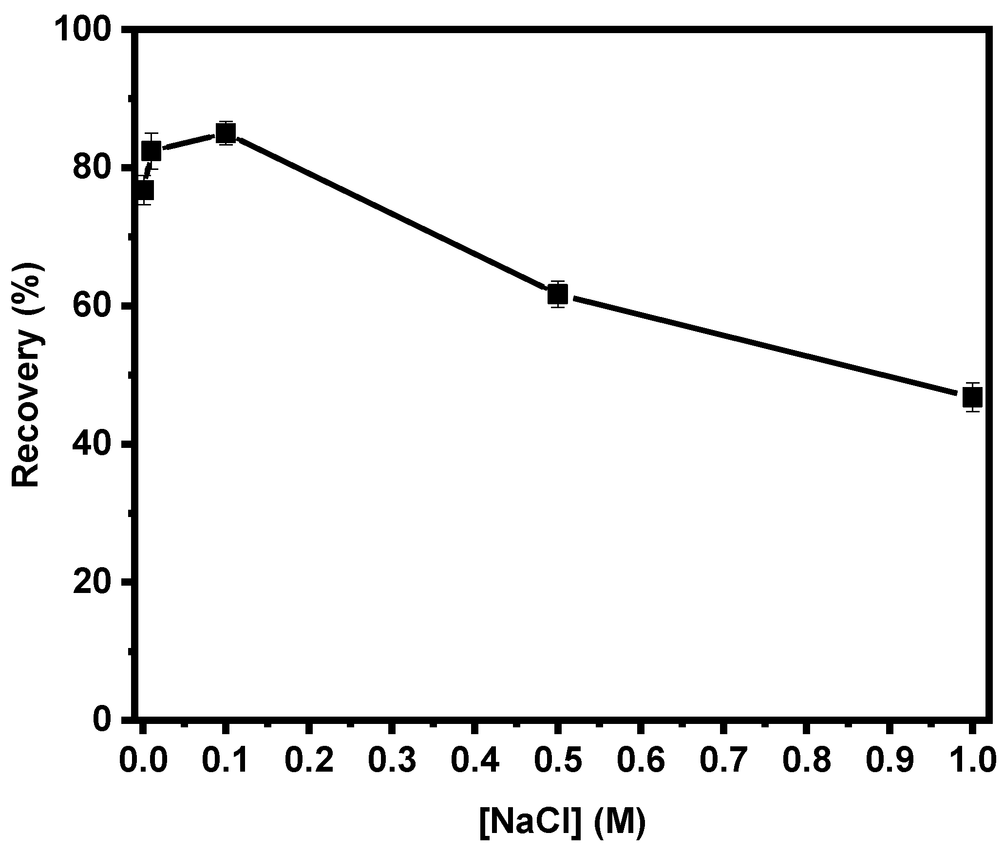
3.3. Effect of Electrolyte Concentration on Combined Flotation

The presence of an electrolyte is of great importance during water electrolysis, mostly for increasing the conductivity of the solution and furthermore by ensuring the efficiency of the process. More specifically, an electrolyte increases the ion conductivity of the solution and decreases the resistance (Ohm law), and therefore there is more voltage available to induce the electrolysis reaction. The current density (J) of the electrolysis unit (I = 0.1 Ampere, a = 50 mm = 5 cm, b = 25 mm = 2.5 cm, c = 1 mm = 0.1 cm, where a, b, c are the dimensions of the electrodes) is: J = 2 × (current intensity/surface area) = 2 × (0.1 A/26.25 cm2) = 0.008 A/cm2 = 80 A/m2. The voltage used was 15 V and the volume of electrolyzed water was 1750 L. Moreover, an inorganic electrolyte increases the surface hydrophobicity of the mineral particles, thus increasing their adhesion to the bubbles diffused in the slurry [48]. In addition, Marrucci et al. argue that the presence of an inorganic electrolyte leads to the avoidance of bubble aggregation and the formation of a stable froth zone [49]. Furthermore, Uchida et al. established that the presence of NaCl can improve the stability of oxygen microbubbles for even more than seven days [50]. On an industrial scale, the salt usage expense could be equilibrated by the higher floated material and/or possibility of using seawater, recycled water, or renewable energy sources. The electrolyte used in the current study was sodium chloride (NaCl) and parameters such as pH (10), collector concentration (120 mg/L), and current density (0.1 A) were kept constant throughout the experiments. The results (Figure 3) illustrate that the addition of electrolyte initially enhances the microbubble-assisted flotation recovery, but when the NaCl concentration exceeds 0.1 M recovery decreases.
The addition of an electrolyte to the slurry leads to an increase of the surface electric potential of the bubbles, thus promoting repulsive forces between bubbles and particles [51], however in cases of excess concentration of mineral salts during flotation, the pulp may have a suppressive effect on the recovery of some particles [52], while bubble aggregation has also been observed [50]. Nevertheless, high electrolyte concentration leads to high electrical conductivity, which results in lower voltage values at the same current density values. This leads to lower energy consumption [53].

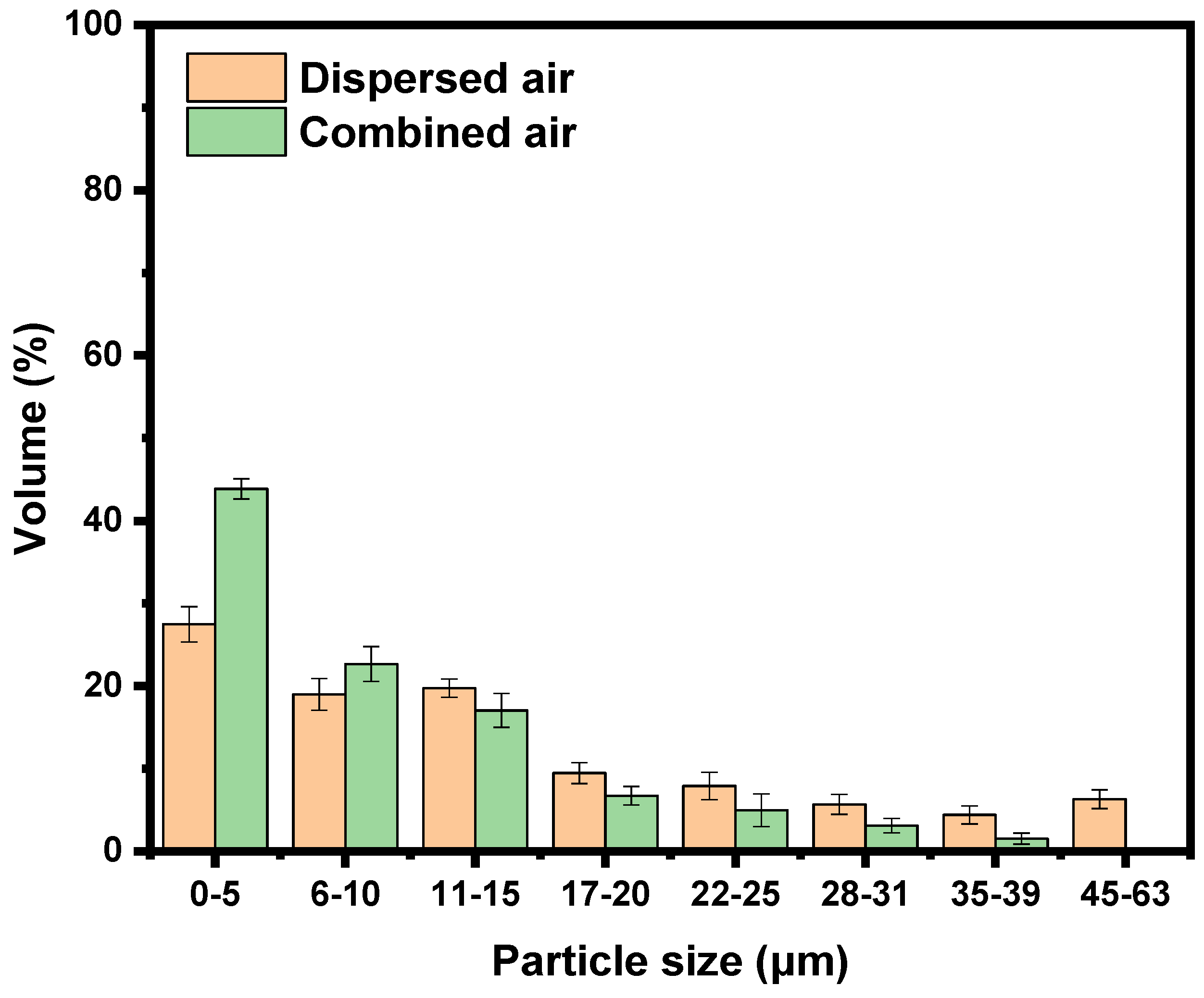
3.4. Particle Size Distribution of Froth Products

Subsequently, particle size analysis of the froth products was performed (Figure 4). The analysis was carried out in the framework of determining the particle size range of magnesite that floated with the experimental conditions studied (combined air). The analysis was carried out on flotation products recovered in the presence and absence of electrolytic bubbles in order to ascertain the contribution of microbubbles to the flotation of fine particles and moreover to conclude which particle fraction affects more. The technique of laser diffraction is to measure the particle size and particle size distribution of materials. This is achieved by measuring the intensity of light scattered as a laser beam passes through a dispersed particulate sample. This data is then analyzed to calculate the size of the particles that created the scattering pattern. Figure 4 illustrates the particle size distribution of (i) magnesite floated by dispersed air bubbles and (ii) magnesite recovered after treatment with electrolytic bubbles. When exclusivelydispersed air bubbles were used, the froth product contained 27.5% magnesite particles sized between 1 and 5 µm, 19 and 20% particles in the range of 6–10 and 11–15 µm respectively, while the largest particles 35–39 and 45–63 µm occupied 4 and 6% of the froth product, respectively. When magnesite was treated with electrolytic bubbles recovery of finer mineral particles occurs. More specifically, the sample contains 44% of particles sized between 0 and 5 µm and the percentage of recovered ultrafine particles has increased by 37.4%. In addition, it is observed that the recovered particles sized in the range of 6–10 µm were increased by 16.2%. Finally, the percentage of larger particles (22–25 µm) decreases by 37%.
The recovery percentage of particles with size >10 μm to some extent decreases and that indicates that the concentrate that derives from combined flotation consists mostly of finer particles Particle size analysis of the recovered mineral is an important indicator that proves that the use of combined air results in fine and ultrafine mineral particle flotation enhancement.

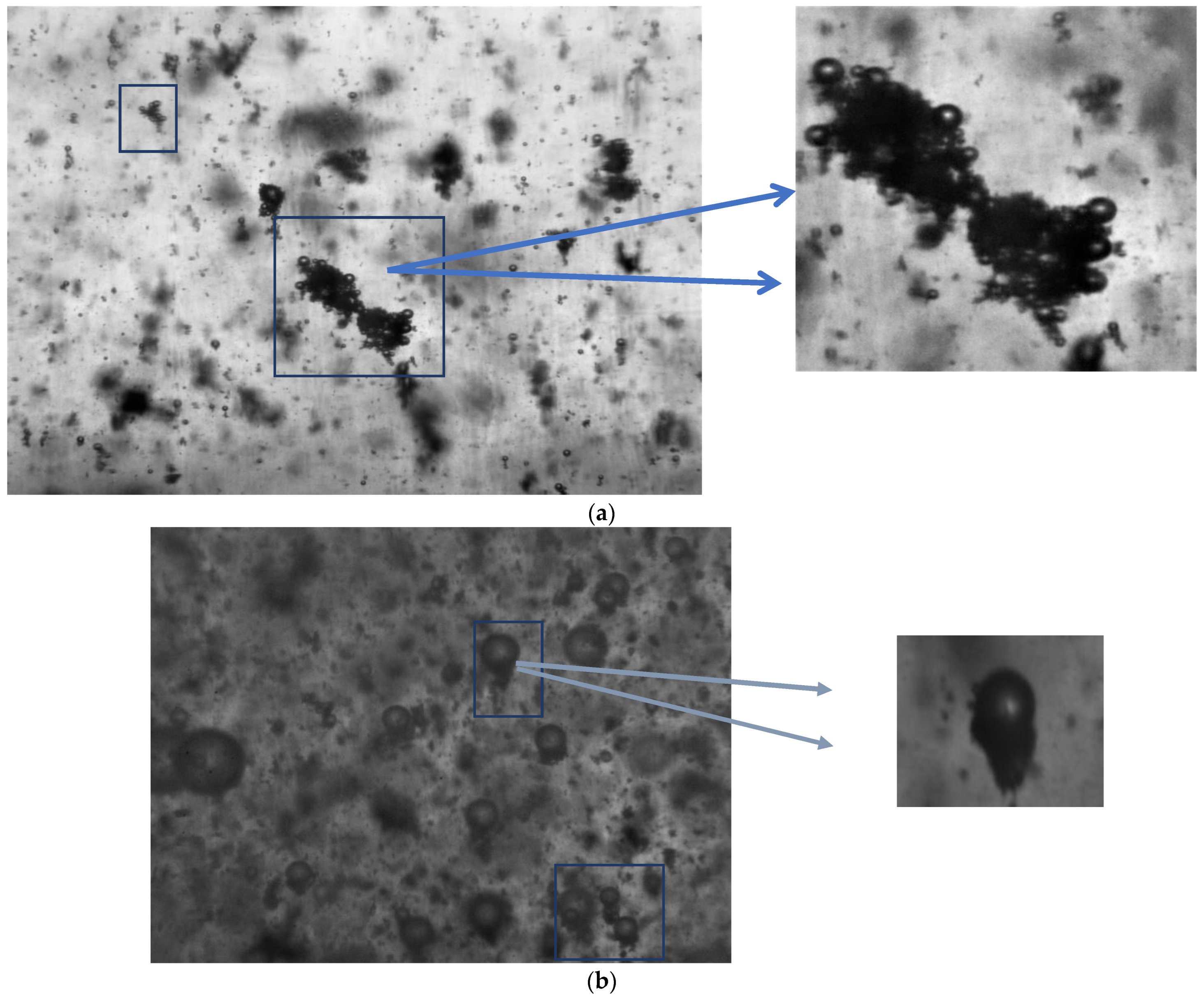
3.5. Flotation Mechanism

In order to further investigate the mechanism regarding the hetero-aggregates of microbubbles and mineral fine particles a high-resolution camera was employed to capture indicative Schemes that prove the corresponding assumption. Figure 5a is a Scheme of the formed hetero-aggregates of microbubbles and particles of magnesite after conditioning occurs. Electrolytic bubbles act as selective flocculants, promoting the formation of particle-microbubble aggregates (flocs), which are then more possible to collide and adhere with conventional flotation bubbles (Figure 5b) [37].
This observation along with experimental findings regarding the promotion of finer particle flotation when combined air is applied is strong evidence that the use of different bubble sizes is beneficial for increasing flotation recovery. These findings confirm the principles of the combined micro-flotation process [54].

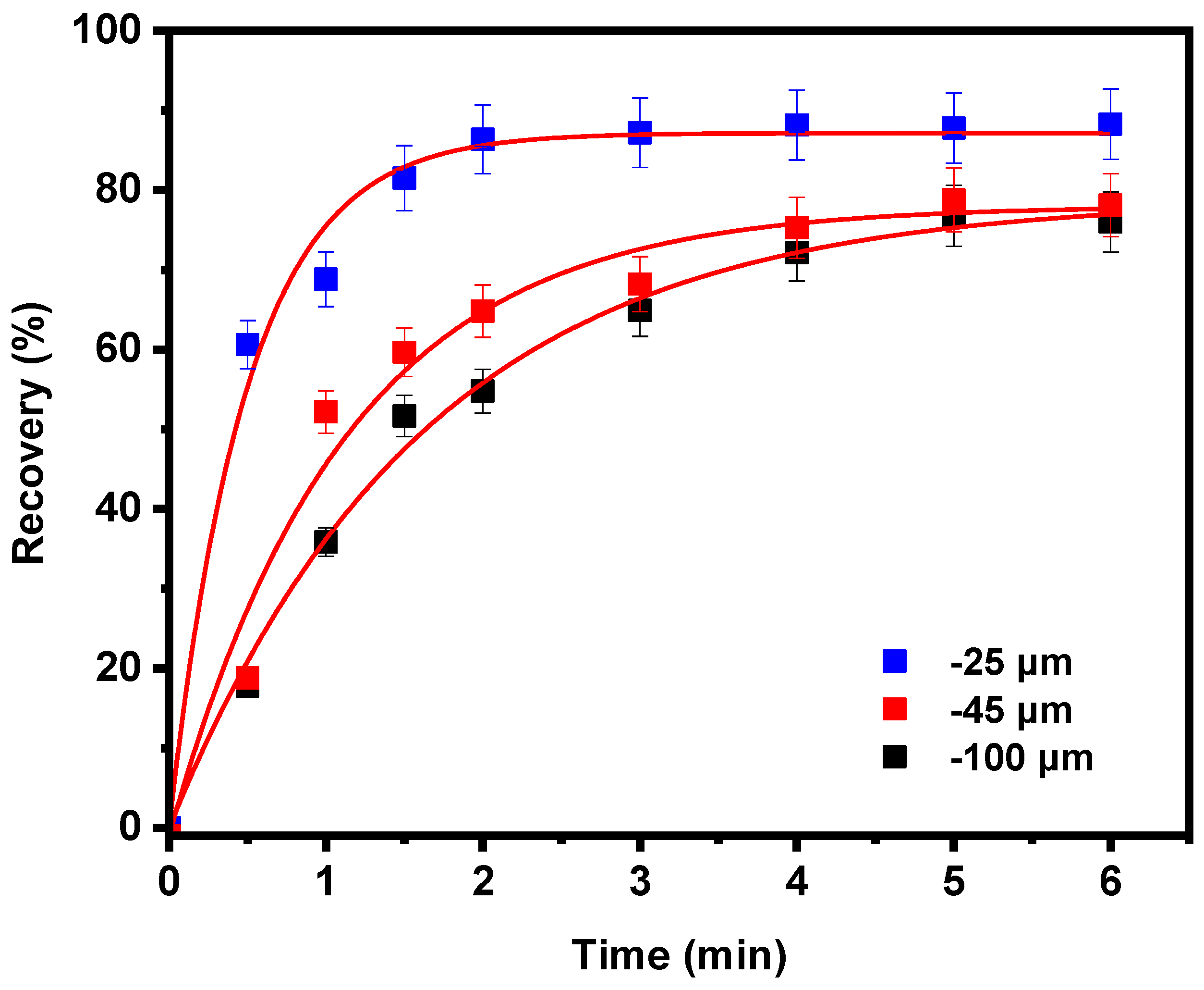
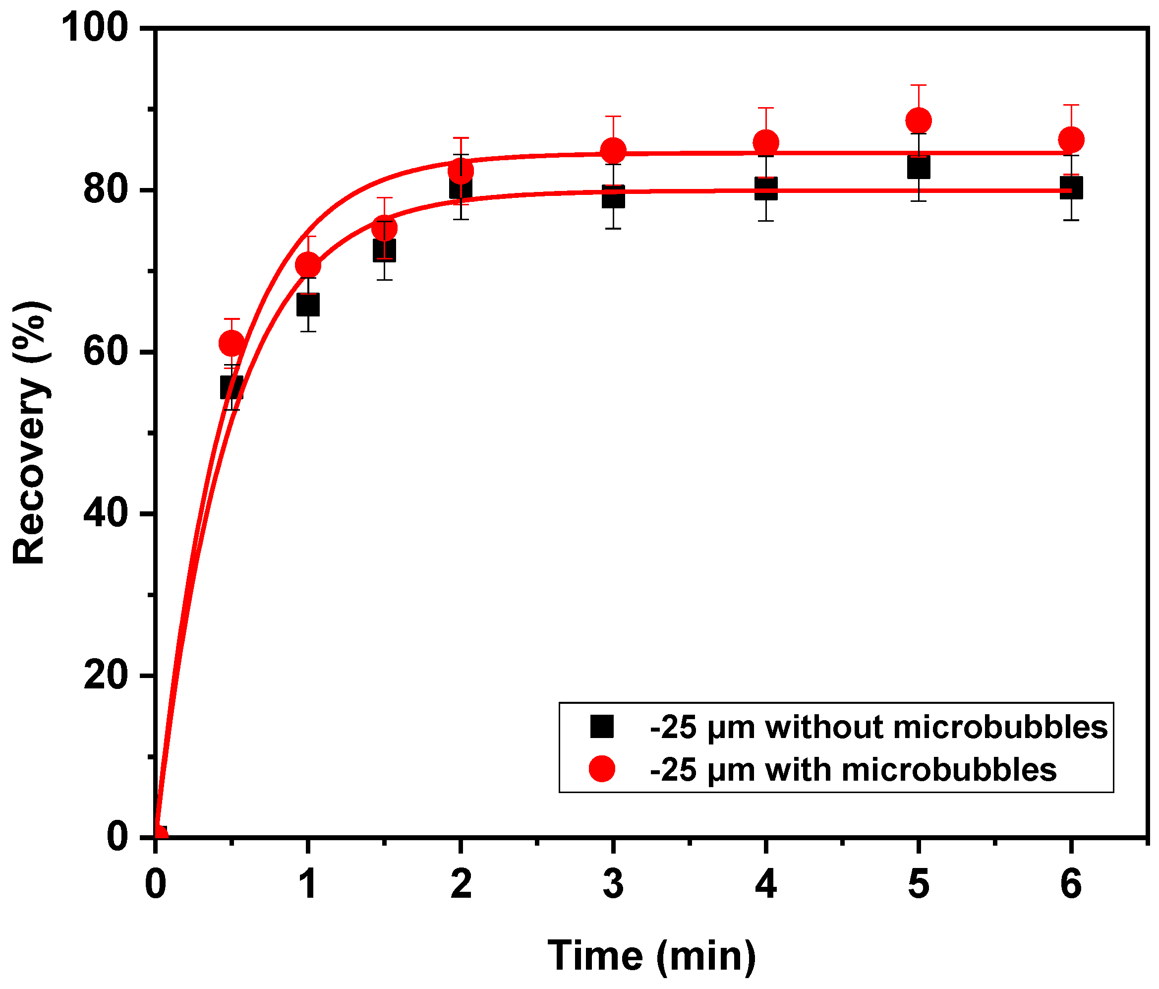
3.6. Flotation Kinetics Study

The most important parameters that affect the performance of a flotation device are the kinetics of the process and the type of flow that dominates during the process. These two parameters conduce to the prediction of the yield of the process and furthermore can contribute to a possible optimization of the method [54]. The recovery rate of the finest particles is faster, and this is attributed to the fact that flotation columns favor the flotation of finer particles due to the fact that they produce bubbles with smaller diameters (spargers), and in addition, a milder turbulent flow field prevails. Fine and ultrafine particles are more likely to attach to smaller bubbles and rise to the froth phase, whereas, in the presence of larger bubbles, they tend to follow the flow lines around them. However, their existence is important for creating turbulence increasing the frequency of bubble particle collisions, and moving the slurry. First and second-order flotation kinetic models were fitted to the experimental data of Figure 6 and the results are given in Table 1. The second-order kinetic model failed to fit the results and therefore the corresponding model parameters are not presented. To that end, kinetic experiments were performed and the effect of flotation time on the recovery of three different grain sizes of magnesite samples (−100, −45, and −25 µm) was examined (Figure 6). The experimental data depict that the finer particles (−25 μm) recover more satisfactorily (by 10%) that the coarser particles. Moreover, the finer fraction (−25 μm) accomplishes the maximum recovery even at the second minute (plateau) while the process for the other two fractions −45 μm and −100 μm completes after 5 min.
The recovery rate of the finest particles is faster, and this is attributed to the fact that flotation columns favor the flotation of finer particles due to the fact that they produce bubbles with smaller diameters (spargers) in addition, a milder turbulent flow field prevails. Fine and ultrafine particles are more likely to attach to smaller bubbles and rise to the froth phase, whereas, in the presence of larger bubbles they tend to follow the flow lines around them [55]. First and second-order flotation kinetic models were fitted to the experimental data of Figure 6 and the results are given in Table 1. The second-order kinetic model failed to fit the results and therefore the corresponding model parameters are not presented. First-order model R = Rmax × (1 − e kt) k corresponds to the first-order rate constant (deterministic) and Rmax to the maximum achievable recovery at t → ∞ [55].
The correlation coefficients (R2) show that the experimental data fit the first-order kinetic model and suggest a uniform dispersed feed and average flotation rate values and show that the particle floatability is constant [56]. Moreover, the results of Table 1 illustrate that the finer particles (−25 µm) have the a higher rate constant (2.01 s−1) compared to the coarser fractions, confirming the fact that the maximum recovery of finer particles is accomplished faster compared to the coarser ones.
In order to investigate the possible contribution/change of the flotation rate of fine (−25 µm), magnesite particles in the presence of microbubbles kinetic experiments occurred. Figure 7 shows the effect of flotation time on the recovery of the finer magnesite fraction in the presence and absence of microbubbles. The graph shows that the flotation process is completed for both cases after 2 min. In addition, higher recovery (by 6%) is achieved in the presence of microbubbles after the third minute.
The data were fitted to the first-order kinetic model and the continuous lines in Figure 7 represent the corresponding fits. Table 2 presents the kinetic parameters: flotation constant k and the value of maximum recovery Rmax, obtained in the presence and absence of electrolytic bubbles. The flotation constant increases from 2.1 to 2.2 min−1(increase by 5%) in the presence of microbubbles, while the addition of microbubbles leads to an increase of the maximum recovery, indicating that magnesite particles that could not float (probably the finest particles with a flotation rate constant close to zero) are now floating.

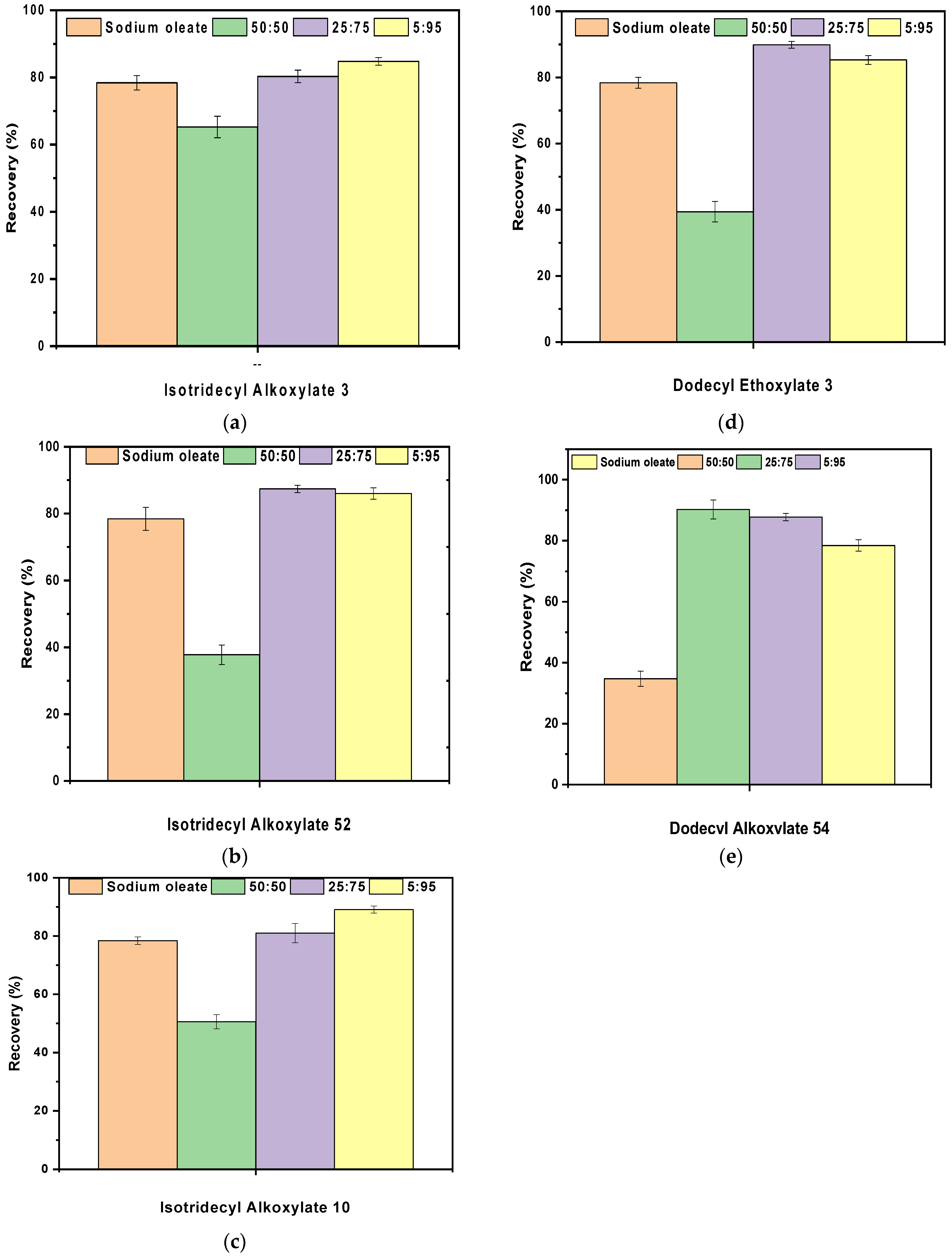
3.7. Synergistic Effect of Anionic/Non Ionic Collectors on Fine Magnesite Flotation

Mainly, carbonate minerals are recovered by using anionic collectors, such as sodium oleate. Anionic collectors have been shown to be effective for carbonate minerals; however, they are not selective between different carbonate minerals. Thus, the addition of nonionic reagents or other additives is often required to enhance the selective adsorption of the anionic collector (main collector). Indeed, the non-ionic surfactants (co-collectors) used in the flotation of carbonate ores are usually synthetic organic reagents produced via fatty alcohol ethoxylation. In mineral flotation that employs fatty acids as the main collector, the use of ethoxylated or alkoxylated modifiers (co-collectors) is quite widespread in industry [57,58,59,60,61,62,63] mainly due to the efficiency they provide, as well as their low cost. The main purpose for adding the nonionic surfactant is to increase the selectivity of the main collector. Moreover, its addition increases the recovery of the target mineral since it enhances the adsorption of the main collector on its surface through the hydrogen bonds that are formed. As a consequence, the density of the adsorbed collector’s layer is increased on the surface of the target mineral, while the repulsive forces of the ionic heads of sodium oleate reduce [31,64,65,66,67,68,69].
Figure 8 shows the effect of single (sodium oleate) and mixed collector systems (non-ionic co-collectors &sodium oleate) on the recovery of magnesite in the presence of dispersed air, at pH 10. It is observed that magnesite recovery takes different values in the presence or absence of the co-collectors. Three co-collector:collector ratios were studied: 50:50, 25:75, and 5:95. When magnesite was conditioned with single sodium oleate recovery reaches 78.4%. The results show that the most effective ratios were 5:95 and 25:75. More specifically, magnesite recovery reached 85 and 89% for the mixtures sodium oleate and Isotridecyl Alkoxylate 3 and Isotridecyl Alkoxylate 10, respectively for the ratio 5:95. When the mixture ratio between co-collector:collector was 25:75 flotation recovery was enhanced by 11.5, 12 and 10% for the co-collectors Dodecyl Ethoxylate 3, Dodecyl Alkoxylate 54 and Isotridecyl Alkoxylate 52, respectively. The ratio of 50:50 resulted in about a 20%–40% reduction in recovery for all five mixtures, indicating that the excess of the co-collector possibly creates an additional adsorption layer making magnesite particles hydrophilic again [45].
There are three main effects of an anionic/nonionic collector mixture: (1) enhancing the adsorption selectivity of the main collector, (2) enhancing the adsorption of the main collector on target minerals, and subsequently (3) increasing mineral recovery [21,49]. The adjuvant effect of the addition of the non-ionic reagent addition is mainly due to their co-adsorption and thus the creation of a mixed adsorption layer. The hydrogen bonds formed increase the density of the adsorption layer and moreover contribute to the reduction of repulsive forces between the ionic heads of the main collector. Overall, this aims to such adisposition of the non-ionic and ionic co-collectors’ heads that enhance the hydrophobicity of the mineral and therefore its recovery. The collector molecules occupy positions on the mineral surface between the existing anionic collector molecules. Therefore, the interactions between the anionic collector molecules are reduced leading to a stronger adsorption layer of the collector ions on the mineral particles and thus its flotation enhancement [65,69,70].

4. Conclusions

In the current research, the construction of a hybrid flotation column (BDDHC) capable of producing bubbles of different sizes by combining conventional-sized bubbles (dispersed air) and micro-bubbles (electrolysis of water) conducted and employed for flotation experiments that lead to fine mineral particles recovery enhancement.
During flotation experiments, the effect of conditioning time with electrolytic bubbles, pH, collector, and electrolyte concentration, with regards to bubble size was studied and moreover, the synergistic effect of anionic/non ionic collectors was examined. The experimental data depict that the presence of electrolytic bubbles enhances the flotation recovery of fine magnesite particles by 7%–8%. Furthermore, particle size analysis of the froth product showed that the presence of electrolytic bubbles enhances the flotation recovery of finer particles more than when employing dispersed-air bubbles exclusively.
  • The experimental results can be concluded as:
  • The maximum treatment time of magnesite fine particles with electrolytic microbubbles with the optimal recovery was 20 min.
  • Flotation experiments realized on the hybrid column with combined air showed an increase of about 8% in fines recovery. In addition, the particle size distribution of the recovered mineral showed an increase of about 37.4% in 0–5 μm particles compared to experiments conducted with dispersed air bubbles exclusively. To this end, it is distinct that the use of combined air favors the recovery of ultra-fine particles.
  • The experimental data deriving from the kinetic study revealed that the experimental data follow the first-order model and furthermore that the particles of smaller particle size (−25 μm) are recovered faster than the other two fractions (−45 and −100 μm).The hybrid column kinetic study showed a 5% increase in the flotation rate of magnesite fines.
  • The maximum ratios between sodium oleate and the non-ionic collectors were 5:95 and 25:75. In addition, maximum recovery was achieved when Dodecyl Alkoxylate 54 was utilized as the co-collector in a ratio of 25:75 increasing magnesite fines recovery by almost 12%.
As a future challenge, the current research can be continued on alarger scale. Moreover, utilization of the hybrid flotation device in a broader range of fine minerals and over a broad range of conditions (collectors, bubbles size, etc.) is encouraged.

Author Contributions

Conceptualization, M.K., T.D.K. and N.K.L.; Data curation, P.K.T.; Investigation, P.K.T.; Supervision, M.K., T.D.K. and N.K.L.; Writing-original draft, P.K.T.; Writing-review and editing, M.K., T.D.K. and N.K.L. All authors have read and agreed to the published version of the manuscript.

Funding

This work was supported by the European Union’s Horizon 2020 research and innovation program under grant agreement No. 821265—FineFuture.

Data Availability Statement

The data presented in this study are available upon request from the corresponding author.

Acknowledgments

The authors would like to acknowledge Grecian Magnesite for providing magnesite samples for this study.

Conflicts of Interest

The authors declare that they have no known competing financial interests or personal relationships that could have appeared to influence the work reported in this paper.

References

  1. Glembotskii, V.A.; Klassen, V.I.; Plaksin, I.N. Flotation; Primary Sources: New York, NY, USA, 1972; p. 633. [Google Scholar]
  2. Pyke, B.; Fornasiero, D.; Ralston, J. Bubble particle heterocoagulation under turbulent conditions. J. Colloid. Interface Sci. 2003, 265, 141–151. [Google Scholar] [CrossRef] [PubMed]
  3. Beloborodov, V.; Fedotov, K. Ways to increase the efficiency of flotation process for complex ores. Oral Session. In Proceedings of the XXI International Mineral Processing Congress, July 23-27, Rome, Italy, 23–27 July 2000; pp. C8b–84–C8b–91. [Google Scholar] [CrossRef]
  4. Gaudin, A.M.; Schuhmann, J.R.; Schlechten, A.W. Flotation Kinetics. II. The Effect of Size on the Behavior of Galena Particles. J. Phys. Chem. 1942, 46, 902–910. [Google Scholar] [CrossRef]
  5. Li, H. The Roles of Non-Polar Oil in Froth Flotation of Fine Particles. Ph.D. Thesis, University of Alberta, Edmonton, AB, Canada, 2018. [Google Scholar] [CrossRef]
  6. Pease, J.D.; Curry, D.C.; Young, M.F. Designing Flotation Circuits for High Fines Recovery; Jameson, G.J., Ed.; Centenary of Flotation Symposium, The Australian Institute of Mining and Metallurgy: Carlton, Australian, 2005; pp. 905–912. [Google Scholar] [CrossRef]
  7. Evans, G.M.; Atkinson, B.W.; Jameson, G.J. The Jameson Cell. In Flotation Science and Engineering; Matis, Ed.; Marcel Dekker: New York, NY, USA, 1995. [Google Scholar]
  8. Mohanty, M.K.; Honaker, R.Q. Performance optimization of Jameson flotation technology for fine coal cleaning. Miner. Eng. 1999, 12, 367–381. [Google Scholar] [CrossRef]
  9. Cowburn, J.; Harbort, G.; Manlapig, E.; Pokrajcic, Z. Improving the recovery of coarse coal particles in a Jameson cell. Miner. Eng. 2006, 19, 609–618. [Google Scholar] [CrossRef]
  10. Jameson, G.J. New Directions in flotation machine design. Miner. Eng. 2010, 23, 835–841. [Google Scholar] [CrossRef]
  11. Trahar, W.J.; Warren, L.J. The flotability of very fine particles—a review. Int. J. Miner. Process. 1976, 3, 103–131. [Google Scholar] [CrossRef]
  12. Fuerstenau, D.W. Fine particle flotation. In Fine Particle Processing, Proceedings International Symposium, Las Vegas, Nevada, 24–28 February 1980; Somasundaran, P., Ed.; American Institute of Mining, Metallurgical, and Petroleum Engineers: Wilkes-Barre, PA, USA, 1980. [Google Scholar]
  13. Yoon, R.H.; Luttrell, G.H. The effect of bubble size on fine particle flotation. Miner. Process. Extr. Metall. 1989, 5, 101–122. [Google Scholar] [CrossRef]
  14. Dai, Z.; Fornasiero, D.; Ralston, J. Particle–bubble collision models—A review. Adv. Colloid Interface Sci. 2000, 85, 231–256. [Google Scholar] [CrossRef]
  15. Read, A.D.; Hollick, C.T. Selective flocculation techniques for recovery of fine particles. Min. Sci. Eng. 1976, 8, 202–213. [Google Scholar]
  16. Rubio, J.; Capponi, F.; Matiolo, E.; Nunes, G.N. Advances in flotation of mineral fines. Proceeding of the XXII International Mineral Processing Congress, Cape Town, South Africa, 29 September–3 October 2003. [Google Scholar]
  17. Somasundaran, P. Selective Flocculation of Fines. The Physical Chemistry of Mineral—Reagent Interactions in Sulfide Flotation; U.S. Bureau of Mines: Washington, DC, USA, 1978. [Google Scholar]
  18. Fornasiero, D.; Filippov, L. Innovations in the flotation of fine and coarse particles. J. Phys. Conf. Ser. 2017, 879, 012002. [Google Scholar] [CrossRef] [Green Version]
  19. Rulyov, N.N. Turbulent microflotation of fine disperse minerals (The general concept). In Proceedings of the Strategic Conference and Workshop: Flotation & Flocculation: From Fundamentals to Applications, Kailua-Kona, Hawai, 28 July–2 August 2003. [Google Scholar]
  20. Ahmed, N.; Jamesson, G.J. The effect of bubble size on the rate of flotation of fine particles. Int. J. Miner. Process. 1985, 14, 195–215. [Google Scholar] [CrossRef]
  21. Lu, S.; Pugh, R.; Forssberg, E. Surface Properties of Particles. In Interfacial Separation of Particles, 20th ed.; Elsevier Science: Amsterdam, The Netherlands, 2005. [Google Scholar]
  22. Zhou, Z.A.; Li, H.; Chow, R.S.; Roberge, K. Role of carrier flotation in accelerating bitumen extraction recovery from mineable Athabasca oil sands. Can. J. Chem. Eng. 2013, 91, 1340–1348. [Google Scholar] [CrossRef]
  23. Yang, B.; Song, S. Hydrophobic agglomeration of mineral fines in aqueous suspensions and its application in flotation: A review. Surf. Rev. Lett. 2014, 21, 1430003. [Google Scholar] [CrossRef]
  24. Kohmuench, J.N.; Luttrell, G.; Mankosa, M. Coarse particle concentration using the HydroFloat Separator. Miner. Metall. Process 2000, 18, 61–67. [Google Scholar] [CrossRef]
  25. Mankosa, M.J.; Kohmuench, J.N.; Christodoulou, L.; Yan, E.S. Improving fine particle flotation using the Stackcell™ (raising the tail of the elephant curve). Miner. Eng. 2018, 121, 83–89. [Google Scholar] [CrossRef]
  26. Koh, P.T.L.; Schwarz, M.P. CFD modelling of bubble–particle collision rates and efficiencies in a flotation cell. Miner. Eng. 2003, 16, 1055–1059. [Google Scholar] [CrossRef]
  27. Hoseinian, F.S.; Rezai, B.; Kowsari, E.; Safari, M. Effect of impeller speed on the Ni(II) ion flotation. Geosyst. Eng. 2019, 22, 161–168. [Google Scholar] [CrossRef]
  28. Hoseinian, F.S.; Rezai, B.; Safari, M.; Deglon, D.A.; Kowsari, E. Effect of hydrodynamic parameters on nickel removal rate from wastewater by ion flotation. J. Environ. Manag. 2019, 244, 408–414. [Google Scholar] [CrossRef]
  29. Filippov, L.O.; Matinin, A.S.; Samiguin, V.D.; Filippova, I.V. Effect of ultrasound on flotation kinetics in the reactor-separator. J. Phys. Conf. Ser. 2013, 416, 012016. [Google Scholar] [CrossRef]
  30. Tsave, P.K.; Kostoglou, M.; Karapantsios, T.D.; Lazaridis, N.K. A Hybrid device for enhancing flotation of fine particles by combining micro-Bubbles with conventional bubbles. Minerals 2021, 11, 561. [Google Scholar] [CrossRef]
  31. Filippova, I.V.; Filippov, L.O.; Duverger, A.; Severov, V.V. Synergetic effect of a mixture of anionic and nonionic reagents: Ca mineral contrast separation by flotation at neutral pH. Miner. Eng. 2014, 66–68, 135–144. [Google Scholar] [CrossRef]
  32. Subrahmanyam, T.V.; Forssberg, K.S.E. Fine particles processing: Shear-flocculation and carrier flotation—A review. Int. J. Miner. Process. 1990, 30, 265–286. [Google Scholar] [CrossRef]
  33. Cho, Y.S.; Laskowski, J.S. Bubble coalescence and its effect on dynamic foam stability. Can. J. Chem. Eng. 2002, 80, 299–305. [Google Scholar] [CrossRef]
  34. Rulyov, N.N. Combined microflotation of fine minerals: Theory and experiment. mineral processing and extractive metallurgy. Trans. Inst. Min. Metall. C 2016, 125, 81–85. [Google Scholar] [CrossRef]
  35. Rulyov, N.N.; Tussupbayev, N.K.; Kravtchenco, O.V. Combined microflotation of fine quartz. Mineral processing and extractive metallurgy. Trans. Inst. Min. Metall. C 2015, 124, 217–233. [Google Scholar] [CrossRef]
  36. Rulyov, N.N.; Filippov, L.O.; Kravchenko, O.V. Combined microflotation of glass beads. Colloids Surf. A Physicochem. Eng. 2020, 598, 124810. [Google Scholar] [CrossRef]
  37. Rulyov, N.N.; Tussupbayev, N.K.; Turusbekov, D.K.; Semushkina, L.V.; Kaldybaeva, Z.A. Effect of Micro-bubbles as Flotation Carriers on Fine Sulphide Ore Beneficiation. Trans. Inst. Min. Metall. C 2018, 127, 133–139. [Google Scholar] [CrossRef]
  38. Sutherland, K.L. Physical Chemistry of Flotation. XI. Kinetics of the Flotation PROCESS. J. Chem. Phys. 1948, 52, 394–425. [Google Scholar] [CrossRef] [PubMed]
  39. Crawford, R.; Ralston, J. The influence of particle size and contact angle in mineral flotation. Int. J. Miner. Process. 1988, 23, 1–24. [Google Scholar] [CrossRef]
  40. Ralston, J.; Dukhin, S.S. The interaction between particles and bubbles. Colloids Surf. A Physicochem. Eng. Asp. 1999, 151, 3–14. [Google Scholar] [CrossRef]
  41. Duan, J.; Fornasiero, D.; Ralston, J. Calculation of the flotation rate constant of chalcopyrite particles in an ore. Int. J. Miner. Process. 2003, 72, 227–237. [Google Scholar] [CrossRef]
  42. Matis, K.A.; Gallios, G.P. Anionic flotation of magnesium carbonates by modifiers. Int. J. Miner. Process. 1989, 25, 261–274. [Google Scholar] [CrossRef]
  43. Brandão, P.R.G.; Poling, G.W. Anionic Flotation of Magnesite. Can. Metall. Q. 1982, 21, 211–220. [Google Scholar] [CrossRef]
  44. Fan, M.; Tao, D.; Honaker, R.; Luo, Z. Nanobubble generation and its application in froth flotation (Part III): Specially designed laboratory scale column flotation of phosphate. Min. Sci. Technol. 2010, 20, 317–338. [Google Scholar] [CrossRef]
  45. Liu, H.; Guofan, Z.; Luo, Y. Effect of depressants in the selective flotation of smithsonite and calcite using cationic collector. Physicochem. Probl. Miner. Process. 2020, 56, 1–10. [Google Scholar] [CrossRef]
  46. Yin, W.; Sun, H.; Tang, Y.; Hong, J.; Yang, B.; Fu, Y.; Han, H. Effect of pulp temperature on separation of magnesite from dolomite in sodium oleate flotation system. Physicochem. Probl. Miner. Process. 2019, 55, 1049–1058. [Google Scholar] [CrossRef]
  47. Bedekovic, G. A study of the effect of operating parameters in column flotation using experimental design. Physicochem. Probl. Miner. Process. 2016, 52, 523–535. [Google Scholar] [CrossRef]
  48. Dishon, M.; Zohar, O.; Sivan, U. From repulsion to attraction and back to repulsion: The effect of NaCl, KCl, and CsCl on the force between silica surfaces in aqueous solution. Langmuir 2009, 25, 2831–2836. [Google Scholar] [CrossRef]
  49. Marrucci, G.; Nicodemo, L. Coalescence of gas bubbles in aqueous solutions of inorganic electrolytes. Chem. Eng. Sci. 1967, 22, 1257–1265. [Google Scholar] [CrossRef]
  50. Uchida, T.; Liu, S.; Enari, M.; Oshita, S.; Yamazaki, K.; Gohara, K. Effect of NaCl on the lifetime of micro-and nanobubbles. Nanomaterials 2016, 6, 31. [Google Scholar] [CrossRef]
  51. Zieminski, S.A.; Whittemore, R.C. Behavior of gas bubbles in aqueous electrolyte solutions. Chem. Eng. Sci. 1971, 26, 509–520. [Google Scholar] [CrossRef]
  52. Montes-Atenas, G.; Garcia-Garcia, F.J.; Mermillod-Blondin, R.; Montes, S. Effect of suspension chemistry onto voltage drop: Application of electro-flotation. Powder Technol. 2010, 204, 1–10. [Google Scholar] [CrossRef]
  53. Huang, C.H.; Shen, S.Y.; Chen, C.W.; Dong, C.D.; Kumar, M.; Dakshinamoorthy, B.; Chang, J.H. Effect of chloride ions on electro-coagulation to treat industrial wastewater containing Cu and Ni. Sustainability 2020, 12, 7693. [Google Scholar] [CrossRef]
  54. Vinnett, L.; Waters, K.E. Representation of Kinetics Models in Batch Flotation as Distributed First-Order Reactions. Minerals 2020, 10, 913. [Google Scholar] [CrossRef]
  55. Wang, D.; Liu, Q. Hydrodynamics of froth flotation and its effects on fine and ultrafine mineral particle flotation: A literature review. Miner. Eng. 2021, 173, 107220. [Google Scholar] [CrossRef]
  56. Rosen, M.J.; Zhu, Z.H. Synergism in binary-mixtures of surfactants. 7. synergism in foaming and its relation to other types of synergism. J. Am. Oil Chem. Soc. 1988, 65, 663–668. [Google Scholar] [CrossRef]
  57. Xiong, Y. Bubble Size Effects in Coal Flotation and Phosphate Reverse Flotation Using a Pico-Nano Bubble Generator. Ph.D. Thesis, West Virginia University, Morgantown, VA, USA, 2014. [Google Scholar]
  58. Sobhy, A.; Tao, D. Nanobubble column flotation of fine coal particles and associated fundamentals. Int. J. Miner. Process. 2013, 124, 109–116. [Google Scholar] [CrossRef]
  59. Fan, M.; Tao, D.; Zhao, Y.; Honaker, R. Effect of nanobubbles on the flotation of different sizes of coal particle. Min. Metall. Explor. 2013, 30, 157–161. [Google Scholar] [CrossRef]
  60. Ma, F.; Tao, D.; Tao, Y. Effects of nanobubbles in column flotation of Chinese sub-bituminous coal. Int. J. Coal Prep. Util. 2019, 1–17, 1142–1146. [Google Scholar] [CrossRef]
  61. Svetovoy, V.B. Spontaneous chemical reactions between hydrogen and oxygen in nanobubbles. Curr. Opin. Colloid Interface Sci. 2021, 52, 101423. [Google Scholar] [CrossRef]
  62. Zhou, W.; Liu, K.; Wang, L.; Zhou, B.; Niu, J.; Ou, L. The role of bulk micro-nanobubbles in reagent desorption and potential implication in flotation separation of highly hydrophobized minerals. Ultrason. Sonochem. 2020, 64, 104996. [Google Scholar] [CrossRef]
  63. Nazari, S.; Shafaei, S.Z.; Hassanzadeh, A.; Azizi, A.; Gharabaghi, M.; Ahmadi, R.; Shahbazi, B. Study of effective parameters on generating submicron (nano)-bubbles using the hydrodynamic cavitation. Physicochem. Probl. Miner. Process. 2020, 56, 884–904. [Google Scholar] [CrossRef]
  64. Filippov, L.O.; Duverger, A.; Filippova, I.V.; Kasaini, H.; Thiry, J. Selective flotation of silicates and Ca-bearing minerals: The role of non-ionic reagent on cationic flotation. Miner. Eng. 2012, 36–38, 314–323. [Google Scholar] [CrossRef]
  65. Guimaraes, R.C.; Araujo, A.C.; Peres, A.E.C. Reagents in igneous phosphate ores flotation. Miner. Eng. 2005, 18, 199–204. [Google Scholar] [CrossRef]
  66. Lovell, V.M. Froth Characteristics in Phosphate Flotation in Flotation; Fuerstenau, M.C., Ed.; Mintek: New York, NY, USA, 1976. [Google Scholar]
  67. Rao, K.H.; Dwari, R.K.; Lu, S.; Vilinska, A.; Somasundaran, P. Mixed anionic/non-ionic collectors in phosphate gangue flotation from magnetite fines. TOMPJ 2010, 4, 14–24. [Google Scholar] [CrossRef] [Green Version]
  68. Sis, H.; Chander, S. Reagents used in the flotation of phosphate ores: A critical review. Miner. Eng. 2003, 16, 577–585. [Google Scholar] [CrossRef]
  69. Sis, H.; Chander, S. Adsorption and contact angle of single and binary mixtures of surfactants on apatite. Miner. Eng. 2003, 16, 839–848. [Google Scholar] [CrossRef]
  70. Chen, C.; Zhu, H.; Sun, W.; Hu, Y.; Qi, W.; Liu, R. Synergetic effect of the mixed anionic/non-ionic collectors in low temperature flotation of scheelite. Minerals 2017, 7, 87. [Google Scholar] [CrossRef] [Green Version]
Scheme 1. (a) The flotation column (b) The hybrid electroflotation column.
Minerals 13 00849 sch001
Scheme 2. (a) Ceramic porous sparger, (b) BDD electrolysis unit.
Minerals 13 00849 sch002
Figure 1. Effect of conditioning time with electrolytic bubbles on the flotation recovery % of magnesite: particle size −25 μm, pH 10, CSO = 120 mg/L, mMgCO3 = 17.5 g, frother = 0.2 mL pine oil.
Minerals 13 00849 g001
Figure 2. Effect of (a) pH and (b) the concentration of collector sodium oleate on the flotation of recovery of magnesite % in the presence of electrolytic, dispersed, and combined bubbles: particle size −25 μm, mMgCO3 = 30 g, frother= 0.2 mL pine oil.
Minerals 13 00849 g002
Figure 3. Effect of the background electrolyte concentration on the flotation % of magnesite by employing combined bubbles: particle size −25 μm, pH 10, CSO = 120 mg/L, mMgCO3 = 17.5 g, frother = 0.2 mL pine oil.
Minerals 13 00849 g003
Figure 4. Particle size distribution of magnesite that floated by employing dispersed air bubbles and magnesite recovered by combining electrolytic and dispersed-air bubbles: pH = 10, [SO] = 120 mg/L, [NaCl] = 0.1 M, frother = 0.2 mL pine oil.
Minerals 13 00849 g004
Figure 5. (a) Scheme of microbubbles and magnesite (−25 μm) hetero-aggregates, (b) Flotation of the formed hetero-aggregates by coarse (conventional) bubbles.
Minerals 13 00849 g005
Figure 6. The recovery of magnesite particles as a function of flotation time: particle sizes −25−45 & −100 μm, pH = 10, [SO] = 120 mg/L, frother = 0.2 mL pine oil.
Minerals 13 00849 g006
Figure 7. The recovery of magnesite particles (−25 μm) as a function of flotation time in the presence and absence of microbubbles: pH = 10, [SO] = 120 mg/L, frother = 0.2 mL pine oil.
Minerals 13 00849 g007
Figure 8. Effect of the co-collector’ (a) Isotridecyl Ethoxylate 3, (b) Dodecyl Ethoxylate 3, (c) Dodecyl Alkoxylate 54, (d) Isotridecyl Alkoxylate 52, (e) Isotridecyl Ethoxylate 10 presence (5:95, 25:75, 50:50–co-collector: sodium oleate), on the flotation recovery % of magnesite: particle size −25 μm, [SO] = 120 mg/L, pH = 10, mMgCO3 = 17.5 g, frother = 0.2 mL pine oil.
Minerals 13 00849 g008
Table 1. Flotation rate constants and maximum recovery, Rmax for magnesite fractions −25, −45, and −100 μm, were obtained by fitting the experimental recovery versus time data with the classical first-order model.
Kinetic ModelMagnesite Fractionk (min−1)Rmax (%)R2
First
order
−100 μm0.61 ± 0.00478.95 ± 1.830.990
−45 μm0.89 ± 0.1178.27 ± 2.800.980
−25 μm2.01 ± 0.1987.17 ± 1.500.990
Table 2. Flotation rate constant, k, and maximum recovery, Rmax, in the absence and presence of microbubbles, obtained by fitting the experimental recovery versus time data with a classical first-order model (kmb and kb refer to the rate constants in the presence and absence of microbubbles, respectively).
k (min−1)Rmax (%)kmb/kbR2
In presence of microbubbles (mb)kmb = 2.2 ± 0.285 ± 1.71.05 ± 0.40.983
Absence of microbubbles (b)kb = 2.1 ± 0.280 ± 1.30.990
Disclaimer/Publisher’s Note: The statements, opinions and data contained in all publications are solely those of the individual author(s) and contributor(s) and not of MDPI and/or the editor(s). MDPI and/or the editor(s) disclaim responsibility for any injury to people or property resulting from any ideas, methods, instructions or products referred to in the content.

