

Investigating the Amenability of a PGM-Bearing Ore to Coarse Particle Flotation

Abstract
:1. Introduction
2. Materials and Methods
2.1. Sample Preparation
2.2. Particle Size Distribution
2.3. Ore Chemistry
2.4. Size by Assay
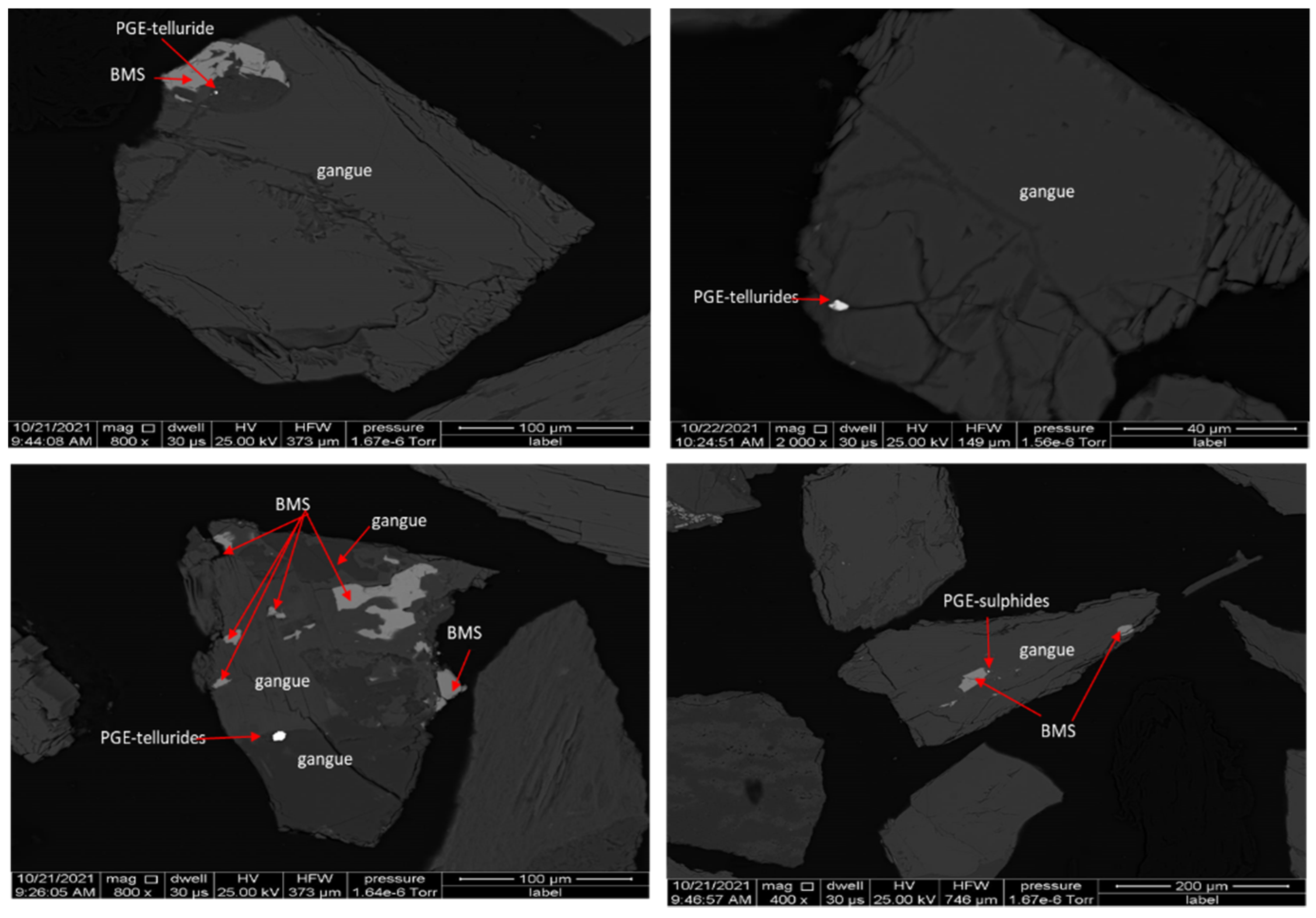
2.5. Mineralogy
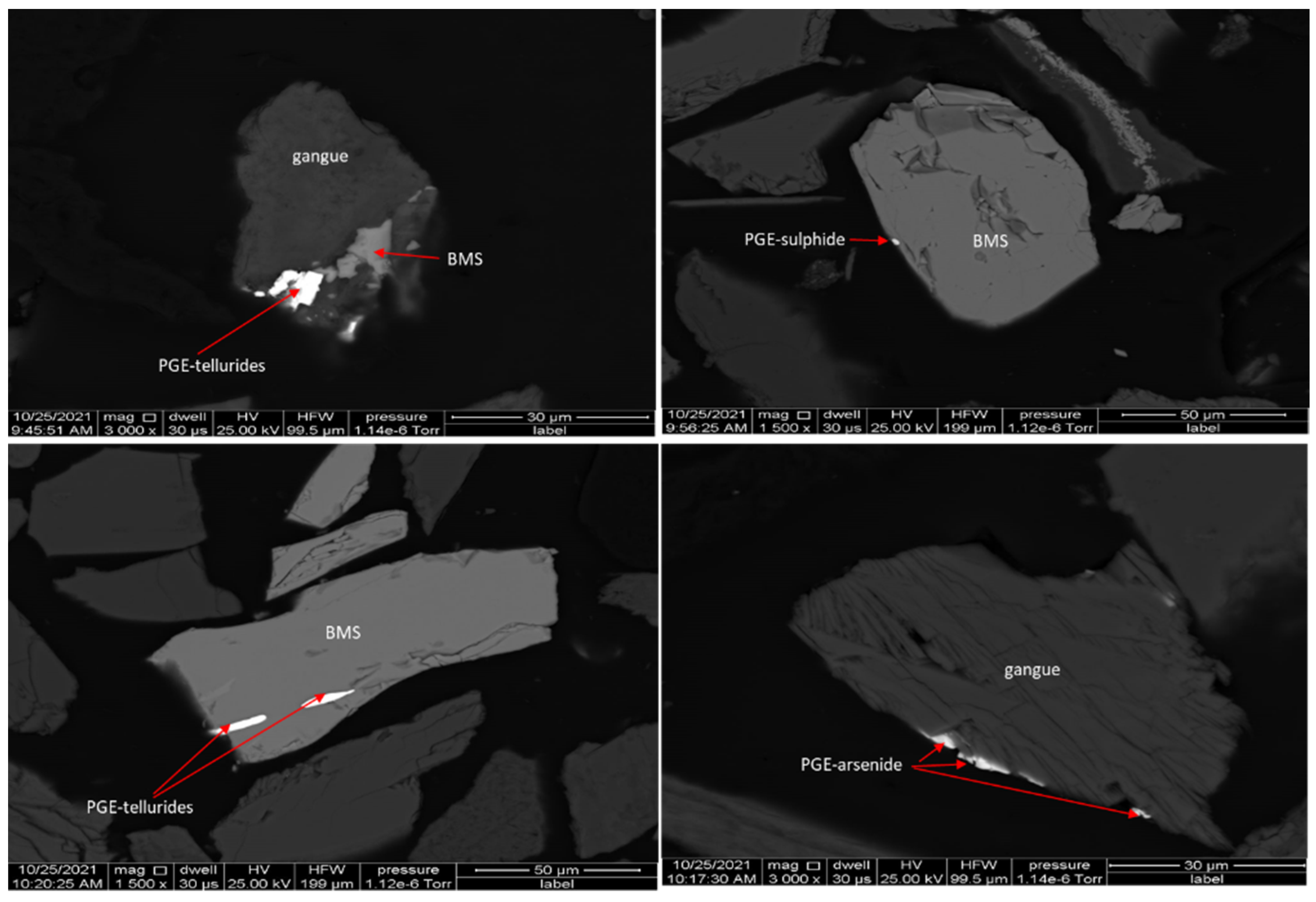
PGM Characteristics
2.6. Hydrofloat Tests and Procedure
2.7. Denver Machine Flotation Tests Procedure
3. Results
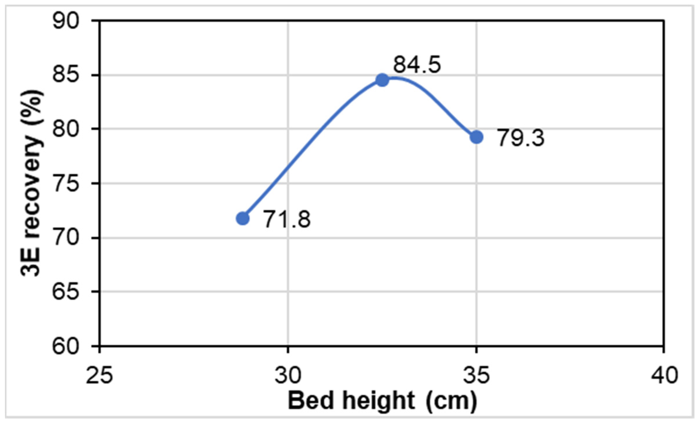
3.1. Effect of Bed Height on the HF Separator Performance
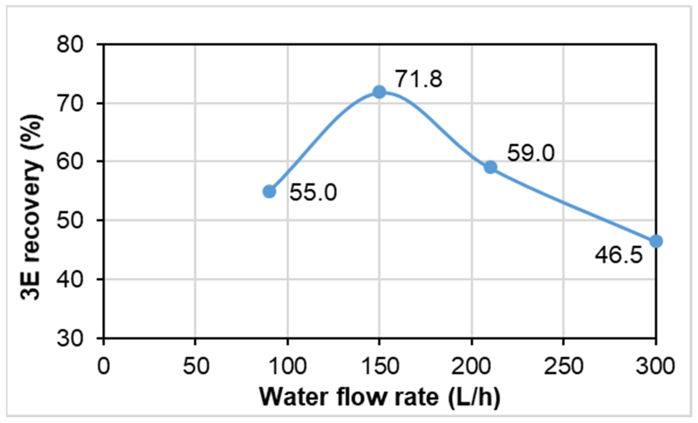
3.2. Effect of Water Flow Rate
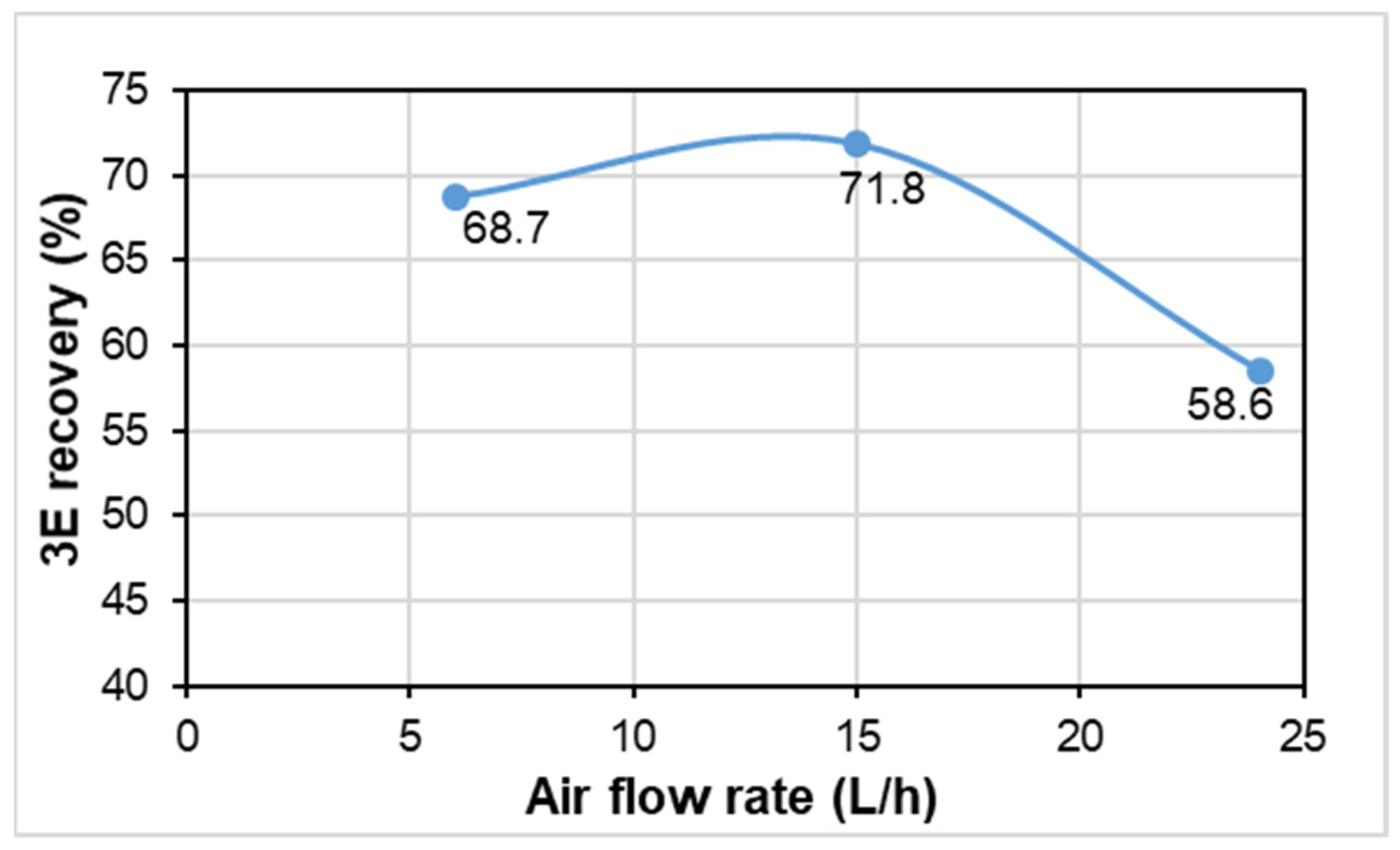
3.3. Effect of Air Flow Rate
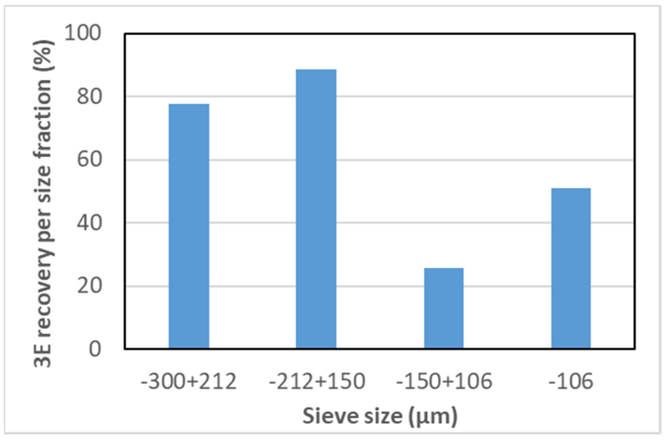
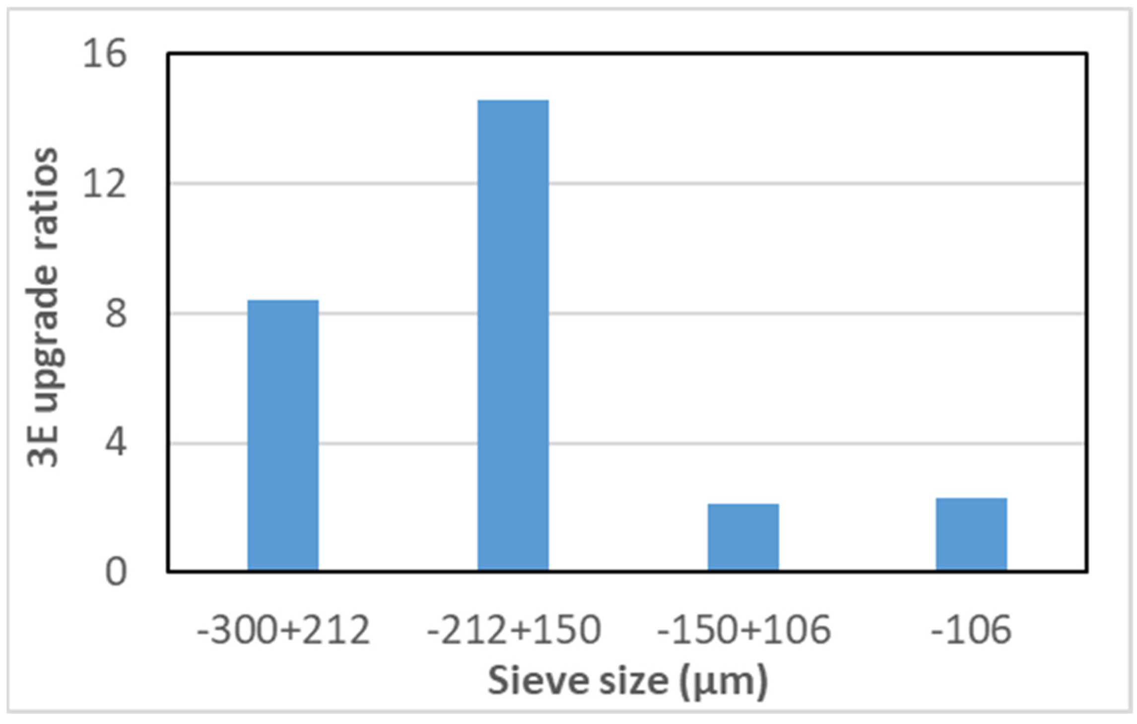
3.4. Recovery by Size Information for Optimised Test
3.5. Characterisation of Flotation Products
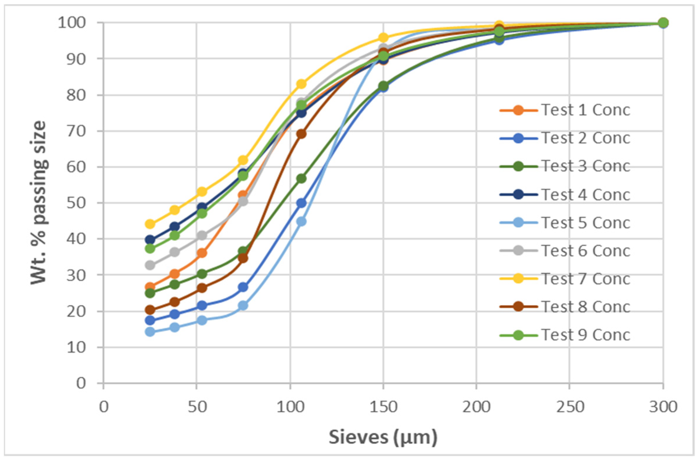
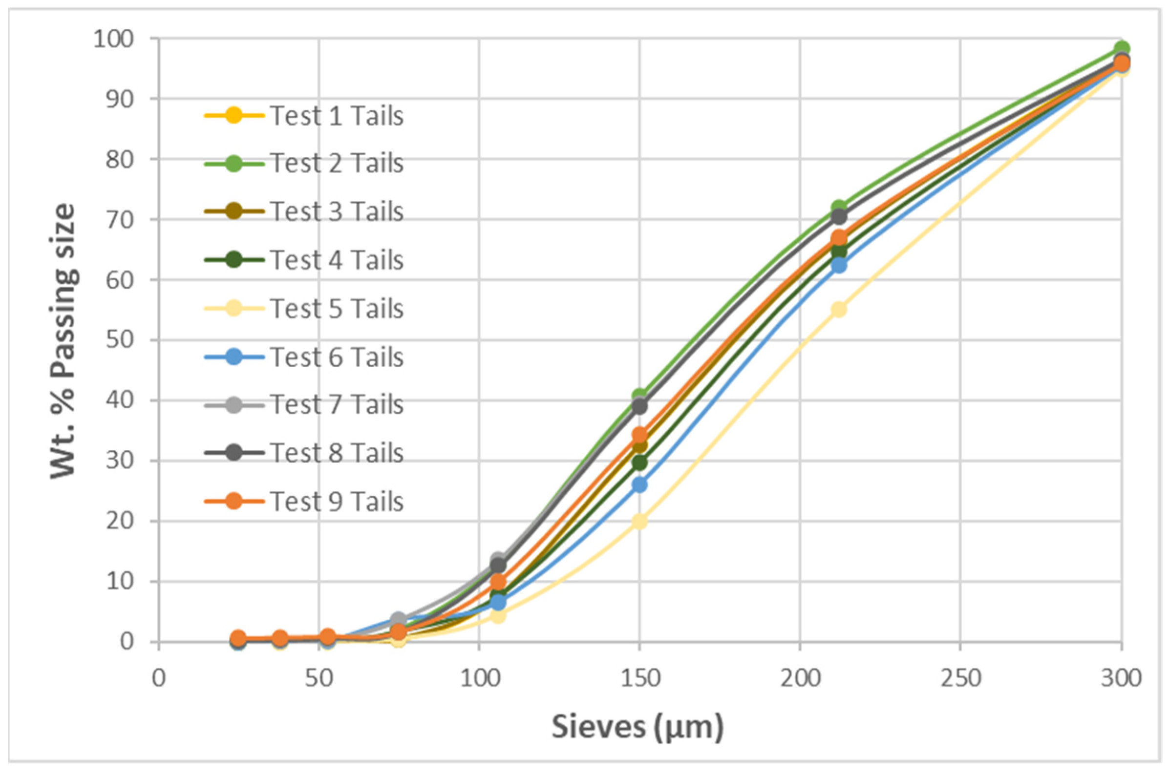
3.5.1. Concentrates and Tailings PSDs
3.5.2. Concentrate and Tailings’ Mineralogy
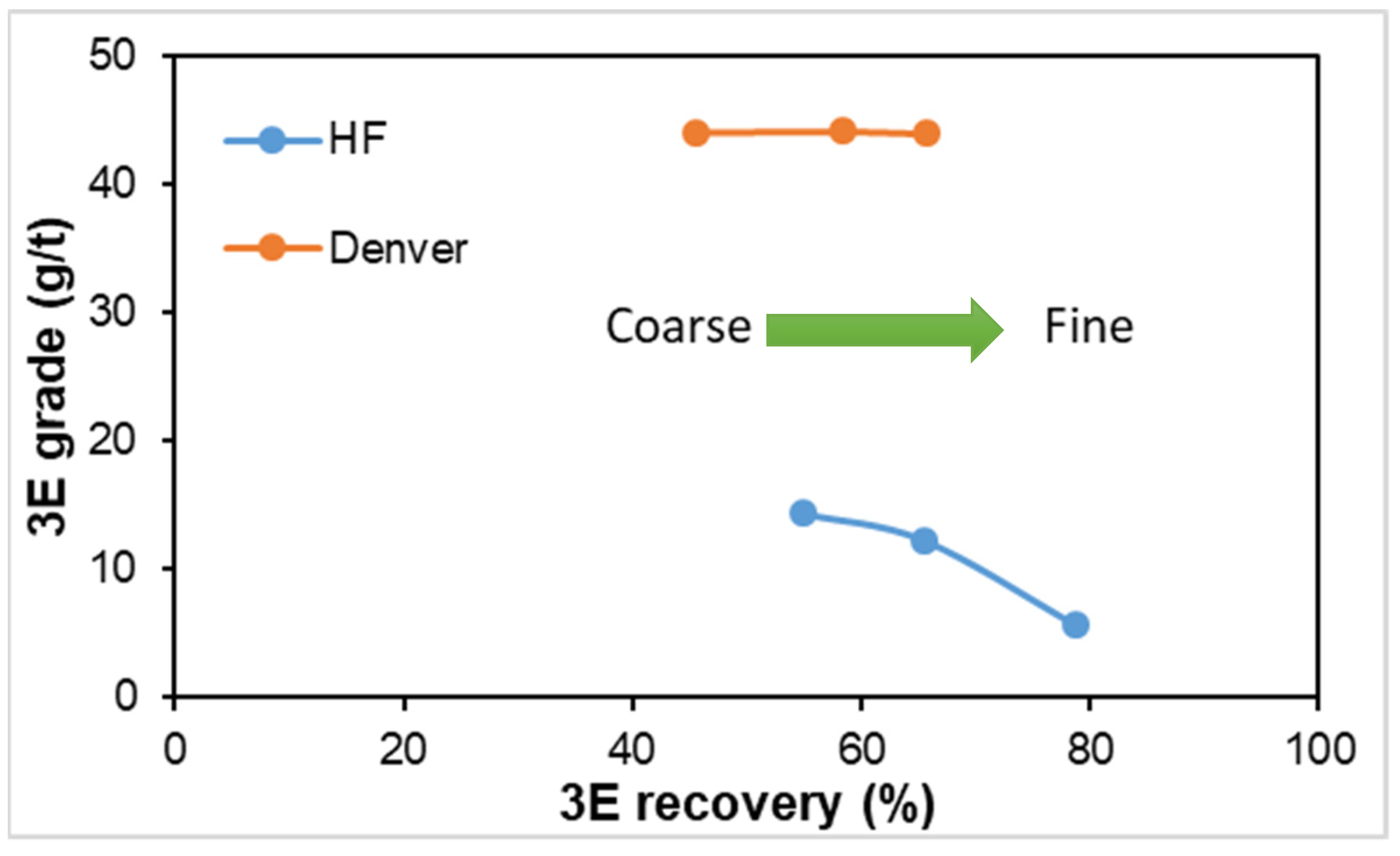
3.6. Hydrofloat vs. Denver Machine CPF Performance
4. Conclusions
Author Contributions
Funding
Data Availability Statement
Acknowledgments
Conflicts of Interest
References
- Schouwstra, R.; Kinloch, E.; Lee, A. A short geological review of the Bushveld Complex. Platin. Met. Rev. 2010, 44, 33. [Google Scholar]
- Von Gruenenwaldt, G. The mineral resources of the Bushveld Complex. Miner. Sci. Eng. 1977, 9, 83–96. [Google Scholar]
- Mwale, A.H.; Musonge, P.; Fraser, D.D. The influence of particle size on energy consumption and water recovery in comminution and dewatering systems. Miner. Eng. 2005, 18, 915–926. [Google Scholar] [CrossRef]
- Zhu, G.; Peng, Y.; Li, Z.; Liu, C.; Li, H. Mechanism of particle size on flotation of PGMs in a fluidised bed flotation column. Miner. Eng. 2020, 151, 106338. [Google Scholar]
- Safari, M.; Harris, M.; Deglon, D. The effect of energy input on the flotation of a platinum ore in a pilot-scale oscillating grid flotation cell. Miner. Eng. 2017, 110, 69–74. [Google Scholar] [CrossRef]
- Hassanzadeh, A.; Safari, M.; Khoshdast, H.; Güner, M.; Hoang, D.; Sambrook, T.; Kowalczuk, P.B. Introducing key advantages of intensified flotation cells over conventionally used mechanical and column cells. Physicochem. Probl. Miner. Process. 2022, 58, 155101. [Google Scholar] [CrossRef]
- Chanturia, V.A.; Ivanova, T.A.; Getman, V.V.; Koporulina, E.V. Methods of minerals modification by the micro-and nanoparticles of gold and platinum for the evaluation of the collectors selectivity at the flotation processing of noble metals from the fine ingrained ores. Miner. Process. Extr. Metall. Rev. 2015, 36, 288–304. [Google Scholar] [CrossRef]
- Safari, M.; Harris, M.; Deglon, D. The effect of energy input on the flotation kinetics of galena in an oscillating grid flotation cell. In Proceedings of the XXVII International Mineral Processing Congress, Santiago, Chile, 20–24 October 2014; Volume 27. [Google Scholar]
- Farrokhpay, S.; Filippov, L.; Fornasiero, D. Flotation of fine particles: A review. Miner. Process. Extr. Metall. Rev. 2021, 42, 473–483. [Google Scholar] [CrossRef]
- Jameson, G.J. New directions in flotation machine design. Miner. Eng. 2010, 23, 835–841. [Google Scholar] [CrossRef]
- Lynch, A.J.; Johnson, N.W.; Manlapig, E.V.; Thorne, C.G. Mineral and Coal Flotation Circuits: Their Simulation and Control; Elsevier Publishing: Amsterdam, The Netherlands, 1981; p. 291. [Google Scholar]
- Schulze, H.J. New theoretical and experimental investigations on stability of bubble/particle aggregates in flotation: A theory on the upper particle size of floatability. Int. J. Miner. Process. 1977, 4, 241–258. [Google Scholar] [CrossRef]
- Testa, F.G.; Safari, M.; Deglon, D.; Leal, L.d.S. Influence of agitation intensity on flotation rate of apatite particles. REM-Int. Eng. J. 2017, 70, 491–495. [Google Scholar] [CrossRef]
- Sahu, P.; Jena, M.S.; Mandre, N.R.; Venugopal, R. Platinum group elements mineralogy, beneficiation, and extraction practices–An overview. Miner. Process. Extr. Metall. Rev. 2021, 42, 521–534. [Google Scholar] [CrossRef]
- Hoseinian, F.S.; Rezai, B.; Safari, M.; Deglon, D.; Kowsari, E. Effect of hydrodynamic parameters on nickel removal rate from wastewater by ion flotation. J. Environ. Manag. 2019, 244, 408–414. [Google Scholar] [CrossRef]
- Paiva, M.; Rubio, J. Factors affecting the floto-elutriation process efficiency of a copper sulphide mineral. Miner. Eng. 2016, 86, 59–65. [Google Scholar] [CrossRef]
- Hoseinian, F.S.; Rezai, B.; Safari, M.; Deglon, D.; Kowsari, E. Separation of nickel and zinc from aqueous solution using triethylenetetramine. Hydrometallurgy 2021, 202, 105609. [Google Scholar] [CrossRef]
- Safari, M.; Deglon, D. Evaluation of an Attachment–Detachment Kinetic Model for Flotation. Minerals 2020, 10, 978. [Google Scholar] [CrossRef]
- Jameson, G.J.; Nguyen, A.V.; Seher, A. The flotation of fine and coarse particles. In Froth Flotation—A Century of Innovation; Fuerstenau, N., Jameson, G., Yoon, R.-H., Eds.; SME: Littleton, CO, USA, 2007; pp. 339–372. [Google Scholar]
- Safari, M.; Hoseinian, F.; Deglon, D.; Filho, L.L.; Pinto, T.S. Investigation of the reverse flotation of iron ore in three different flotation cells: Mechanical, oscillating grid and pneumatic. Miner. Eng. 2020, 150, 106283. [Google Scholar] [CrossRef]
- Trahar, W.J.; Warren, L.J. The floatability of very fine particles—A review. Int. J. Miner. Process. 1976, 3, 103–131. [Google Scholar] [CrossRef]
- Safari, M.; Deglon, D. An attachment-detachment kinetic model for the effect of energy input on flotation. Miner. Eng. 2018, 117, 8–13. [Google Scholar] [CrossRef]
- Rinne, A.; Peltola, A. On lifetime costs of flotation operations. Miner. Eng. 2008, 21, 846–850. [Google Scholar] [CrossRef]
- Kohmuench, J.N.; Thanasekaran, H.; Seaman, B. Advances in coarse particle flotation: Copper and gold. In Proceedings of the AusIMM MetPlant Conference, Perth, Australia, 14–17 July 2013; p. 11. [Google Scholar]
- Mankosa, M.J.; Kohmuench, J.N.; Christodoulou, L.; Luttrell, G.H. Recovery of values from a porphory copper tailings stream. In Proceedings of the XXVIII International Mineral Processing Congress, Québec City, QC, Canada, 11–15 September 2016; p. 457. [Google Scholar]
- Carelse, C.; Manuel, M.; Chetty, D.; Taguta, J.; Safari, M.; Youlton, K. The flotation behaviour of liberated Platinum Group minerals in Platreef ore under reduced reagent conditions. Miner. Eng. 2022, 190, 107913. [Google Scholar] [CrossRef]
- Miller, J.D.; Lin, C.L.; Wang, Y.; Mankosa, M.J.; Kohmuench, J.N.; Luttrell, G.H. Significance of exposed grain surface area in coarse particle flotation of low-grade gold ore with the HydrofloatTM technology. In Proceedings of the XXVIII International Mineral Processing Congress, Quebec City, QC, Canada, 11–15 September 2016. [Google Scholar]
- Fosu, S.; Awatey, B.; Skinner, W.; Zanin, M. Flotation of coarse composite particles in mechanical cell vs. the fluidised-bed separator (The HydroFloat™). Miner. Eng. 2015, 77, 137–149. [Google Scholar] [CrossRef]
- Awatey, B.; Thanasekaran, H.; Kohmuench, J.; Skinner, W.; Zanin, M. Optimization of operating parameters for coarse sphalerite flotation in the HydroFloatTM fluidised-bed separator. Miner. Eng. 2013, 50–51, 99–105. [Google Scholar] [CrossRef]
- Awatey, B.; Thanasekaran, H.; Kohmuench, J.N.; Skinner, W.; Zanin, M. Critical contact angle for coarse sphalerite flotation in a fluidised-bed separator vs. a mechanically agitated cell. Miner. Eng. 2014, 60, 51–59. [Google Scholar] [CrossRef]
- Tariqul Islam, M.D.; Nguyen, A.N. A numerical study with experimental validation of liquid-assisted fluidisation of particle suspensions in a HydroFloat cell. Miner. Eng. 2019, 134, 176–192. [Google Scholar] [CrossRef]
- Xu, D.; Ametov, I.; Grano, S.R. A study of detachment of coarse particles from bubbles using novel electro-acoustical technique. In Proceedings of the CHEMECA 2009, Perth, Australia, 27–30 September 2009. [Google Scholar]
- Gontijo, C. Coarse Particle Flotation. Ph.D. Thesis, University of South Australia, Adelaide, Australia, 2009. [Google Scholar]
- Hassanzadeh, A.; Safari, M.; Hoang, D.H.; Khoshdast HAlbijanic, B.; Kowalczuk, P.B. Technological assessments on recent developments in fine and coarse particle flotation systems. Miner. Eng. 2022, 180, 107509. [Google Scholar] [CrossRef]
- Nazari, S.; Shafaei, S.Z.; Gharabaghi, M.; Ahmadi, R.; Shahbazi, B.; Maoming, F. Effects of nanobubble and hydrodynamic parameters on coarse quartz flotation. Int. J. Min. Sci. Technol. 2019, 29, 289–295. [Google Scholar] [CrossRef]
- Nazari, S.; Ziaedin Shafaei, S.; Hassanzadeh, A.; Azizi, A.; Gharabaghi, M.; Ahmadi, R.; Shahbazi, B. Study of effective parameters on generating sub-micron (nano)-bubbles using hydrodynamic cavitation. Phyisicochem. Probl. Miner. Process. 2020, 56, 884–904. [Google Scholar] [CrossRef]
- Fan, M.; Tao, D. A study on picobubble enhanced coarse phosphate froth flotation. Sep. Sci. Technol. 2008, 43, 1–10. [Google Scholar] [CrossRef]
- Safari, M.; Hoseinian, F.; Deglon, D.; Leal Filho, L.; Souza, T. Impact of flotation operational parameters on the optimization of fine and coarse Itabirite iron ore beneficiation. Powder Technol. 2022, 408, 117772. [Google Scholar] [CrossRef]
- Mohlala, M.; Ramonotsi, K.; Makhatha, M. The effect of collector dosage and particle size on coarse particle flotation of platinum group minerals in the Merensky Reef. Miner. Eng. 2022, 179, 107052. [Google Scholar]
- Fan, Y.; Cao, B.; Guo, Y.; Liu, L. Coarse particle flotation of PGMs using a fluidised bed flotation cell with nonionic surfactant. Miner. Eng. 2021, 169, 107111. [Google Scholar]
- Li, X.; Xia, L.; Chen, L.; Wang, C. Optimization of a fluidised bed flotation column for coarse particle flotation of low-grade sulfide ore. Miner. Eng. 2020, 157, 106518. [Google Scholar]
- Alabi, A.O.; Dlamini, T.B.; Ndlovu, B.; Makhatha, M.M. Performance of a new type of froth flotation cell for coarse particles. Miner. Eng. 2020, 151, 106343. [Google Scholar]
- Ma, M.; Song, S.; Ke, X.; Liu, G. Recovery of platinum group metals from low-grade sulfide ores by coarse particle flotation. Miner. Eng. 2021, 163, 106818. [Google Scholar]
- Dube, T.; Bradshaw, D.J.; Harris, P.J. Coarse particle flotation for improving the recovery of valuable minerals in traditional flotation circuits. Miner. Eng. 2020, 145, 106115. [Google Scholar]
- Ghorbani, Y.; Zhang, S.E.; Nwaila, G.T.; Bourdeau, J.E.; Safari, M.; Hadi Hoseinie, S.; Nwaila, P.; Ruuska, J. Dry laboratories—Mapping the required instrumentation and infrastructure for online monitoring, analysis, and characterization in the mineral industry. Miner. Eng. 2023, 191, 107971. [Google Scholar]
- Danha, G.M.; Shengo, M.; Muzenda, E. Review on the optimisation of platinum group metal recovery through flotation. Miner. Eng. 2020, 157, 106467. [Google Scholar]
- Zhang, K.; Song, S.; Li, Q.; Chen, L.; Zhang, L.; Zhou, J. The effect of conditioning time, collector dosage, collector type, and pH on the recovery of PGMs from a low-grade ore by flotation. Minerals 2019, 9, 368. [Google Scholar]


| 3E | Cu | Ni | Fe | Total S |
|---|---|---|---|---|
| (g/t) | (%) | (%) | (%) | (%) |
| 2.59 | 0.08 | 0.16 | 6.39 | 0.28 |
| Sieve Size (µm) | Mass (g) | Mass (%) | Grade | Mass Distribution (%) | ||||
|---|---|---|---|---|---|---|---|---|
| 3E (g/t) | Cu (%) | Ni (%) | 3E | Cu | Ni | |||
| +300 | 6.72 | 2.3 | 2.59 | 0.063 | 0.10 | 2.9 | 1.3 | 2.1 |
| −300 + 212 | 68.31 | 23.2 | 2.36 | 0.062 | 0.09 | 26.5 | 13.0 | 20.3 |
| −212 + 150 | 81.77 | 27.7 | 1.75 | 0.073 | 0.10 | 23.5 | 18.4 | 25.8 |
| −150 + 106 | 76.83 | 26.1 | 1.62 | 0.11 | 0.10 | 20.4 | 26.0 | 24.5 |
| −106 | 61.07 | 20.7 | 2.67 | 0.22 | 0.14 | 26.8 | 41.3 | 27.3 |
| Total | 294.7 | 100.0 | 100.0 | 100.0 | 100.0 | |||
| Liberation Characteristic | PGM vol (%) | |
|---|---|---|
| Concentrate | Tailings | |
| Liberated PGMs | 7.1 | n.d. |
| PGMs associated with liberated BMS (base metal sulphides) | 1.0 | 1.0 |
| PGMs associated with BMS locked in silicate or oxide gangue particles | 0.6 | n.d. |
| PGMs attached to silicate or oxide gangue particles | 2.4 | 9.8 |
| PGMs associated with BMS attached to silicate or oxide gangue particles | 85.2 | 60.7 |
| PGMs locked within silicate or oxide gangue particles | 3.7 | 28.6 |
| 100 | 100 | |
| Number of grains | 119 | 64 |
| Size Class (µm) | MP (%) | 3E Recovery (%) | ||
|---|---|---|---|---|
| HF | DENVER | HF | DENVER | |
| +212 − 250 | 7.9 | 1.8 | 55.0 | 45.6 |
| +150 − 212 | 13.9 | 2.7 | 65.5 | 58.4 |
| +106 − 150 | 41.1 | 3.4 | 78.8 | 65.7 |
Disclaimer/Publisher’s Note: The statements, opinions and data contained in all publications are solely those of the individual author(s) and contributor(s) and not of MDPI and/or the editor(s). MDPI and/or the editor(s) disclaim responsibility for any injury to people or property resulting from any ideas, methods, instructions or products referred to in the content. |
© 2023 by the authors. Licensee MDPI, Basel, Switzerland. This article is an open access article distributed under the terms and conditions of the Creative Commons Attribution (CC BY) license (https://creativecommons.org/licenses/by/4.0/).
Share and Cite
Taguta, J.; Safari, M.; Govender, V.; Chetty, D. Investigating the Amenability of a PGM-Bearing Ore to Coarse Particle Flotation. Minerals 2023, 13, 698. https://doi.org/10.3390/min13050698
Taguta J, Safari M, Govender V, Chetty D. Investigating the Amenability of a PGM-Bearing Ore to Coarse Particle Flotation. Minerals. 2023; 13(5):698. https://doi.org/10.3390/min13050698
Chicago/Turabian StyleTaguta, Jestos, Mehdi Safari, Veruska Govender, and Deshenthree Chetty. 2023. "Investigating the Amenability of a PGM-Bearing Ore to Coarse Particle Flotation" Minerals 13, no. 5: 698. https://doi.org/10.3390/min13050698