
A New Approach for Analyzing Circular Tunnels in Nonlinear Strain-Softening Rock Masses Considering Seepage Force

Abstract
:1. Introduction
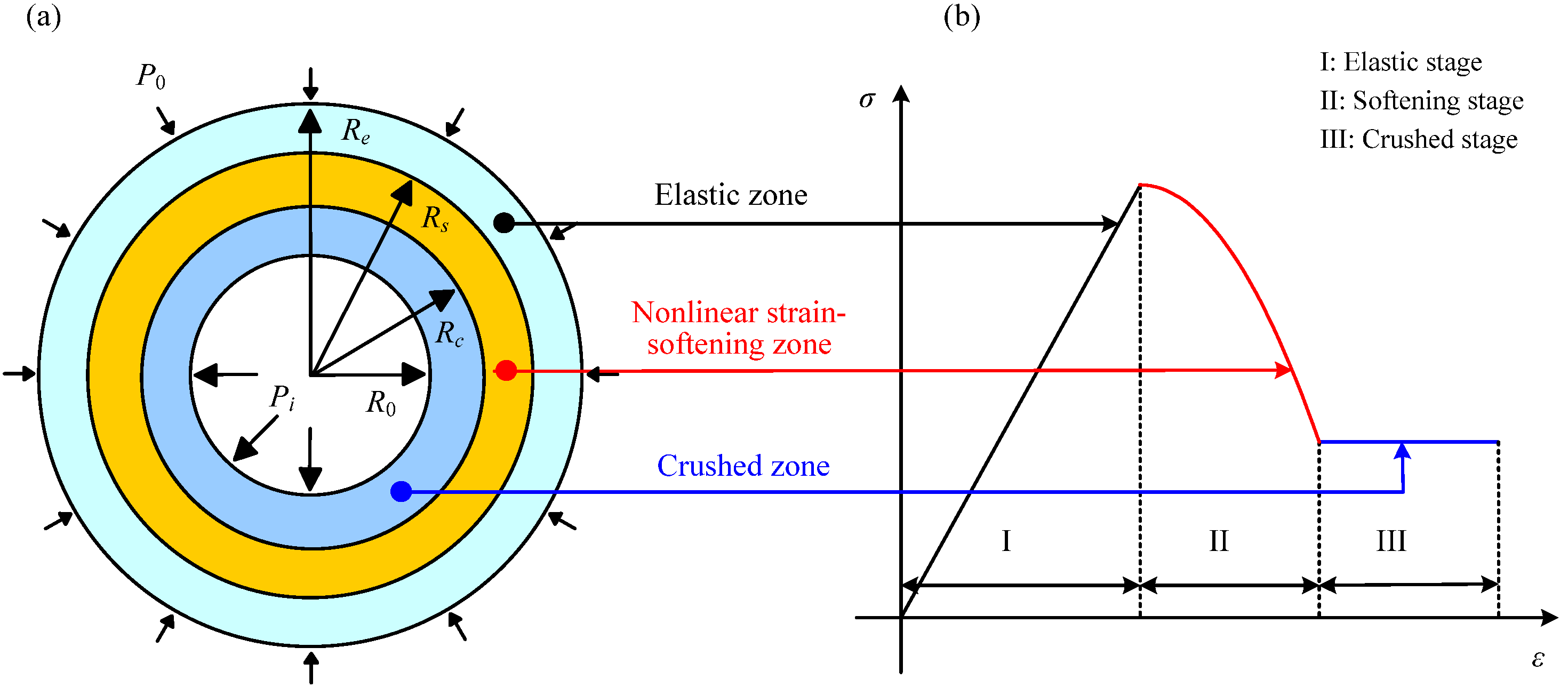
2. Model Establishment
3. Mechanical Analysis
- 1.
- Equilibrium differential formula:
- 2.
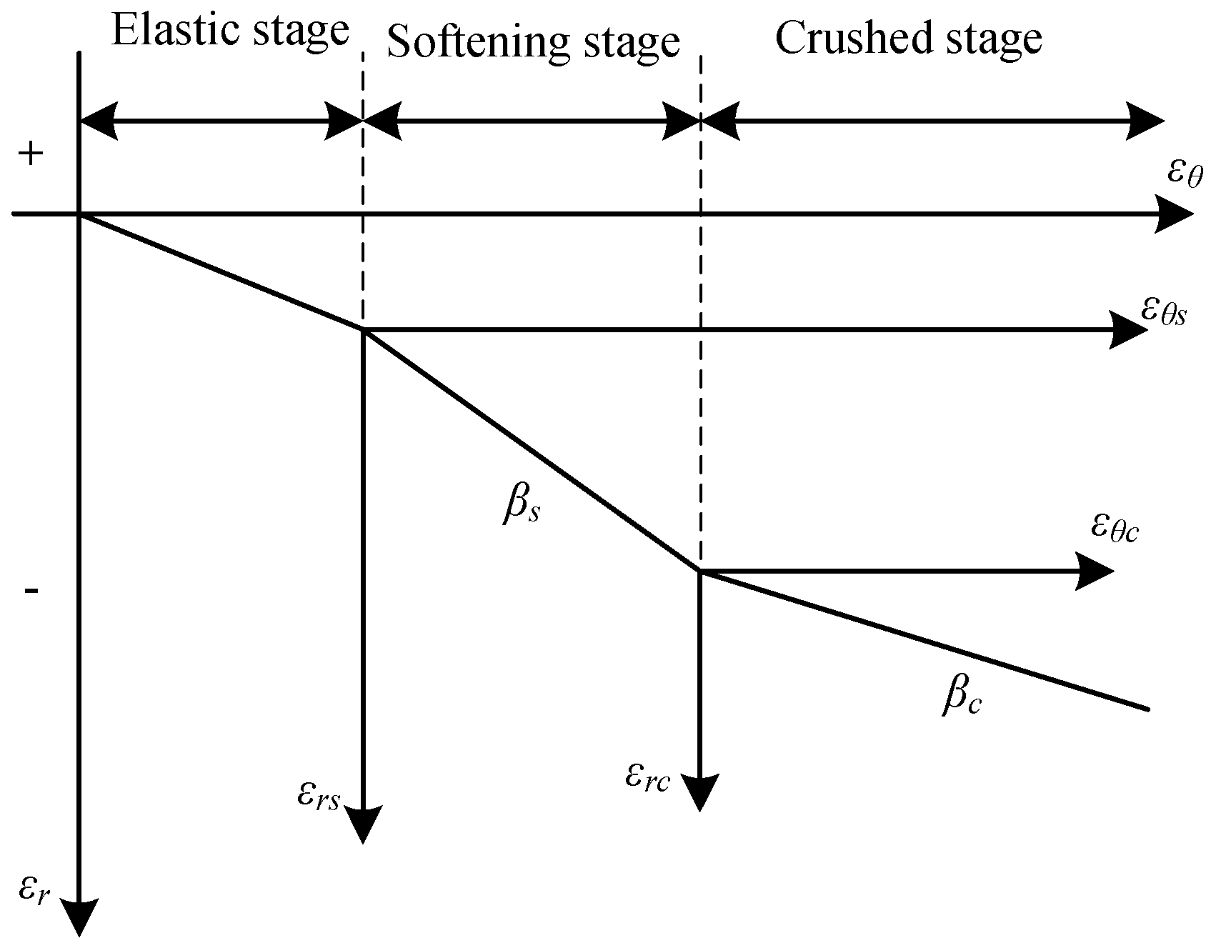
- Geometric formula:
- 3.
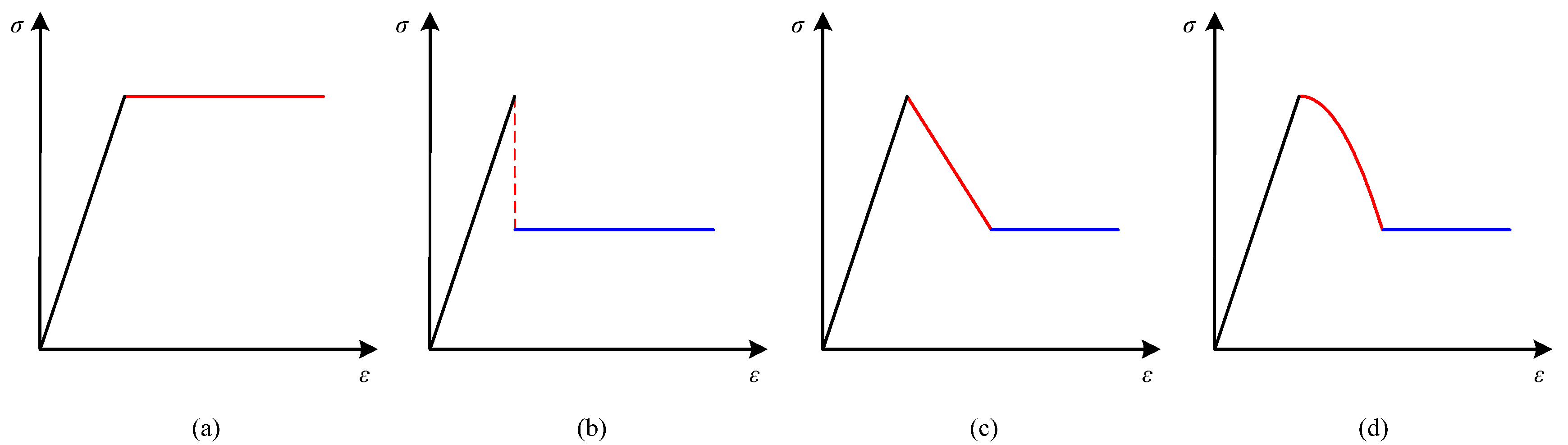
- Constitutive formula:
- 4.
- Mogi-Coulomb strength criterion:
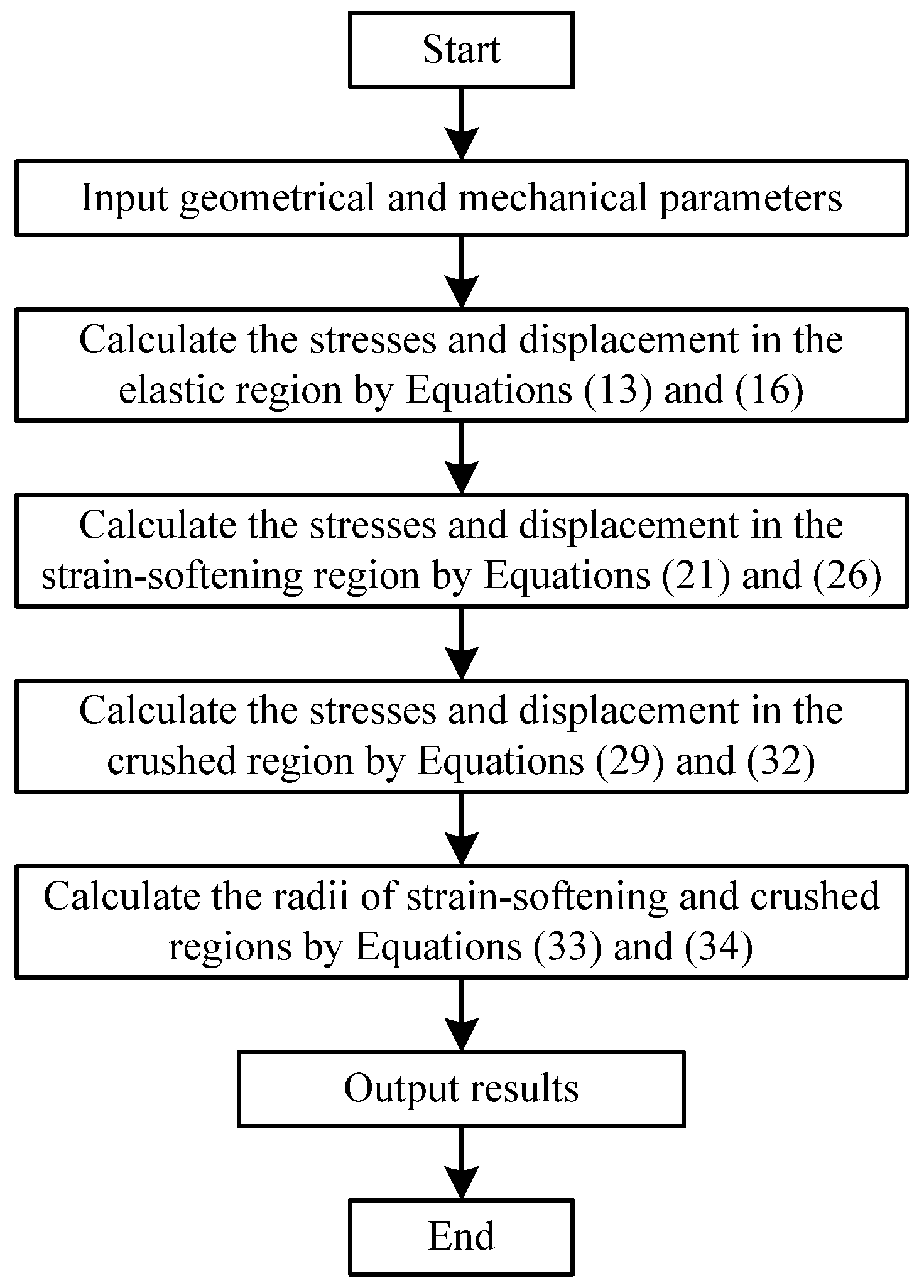
3.1. Stresses and Displacement in the Elastic Region
3.2. Stresses and Displacement in the Strain-Softening Region
3.3. Stresses and Displacement in the Crushed Region
3.4. Radii of Strain-Softening and Crushed Regions
4. Special Cases Discussion
4.1. Kastner’s Formula
4.2. Wilson’s Formula
5. Parameter Sensitivity Analysis
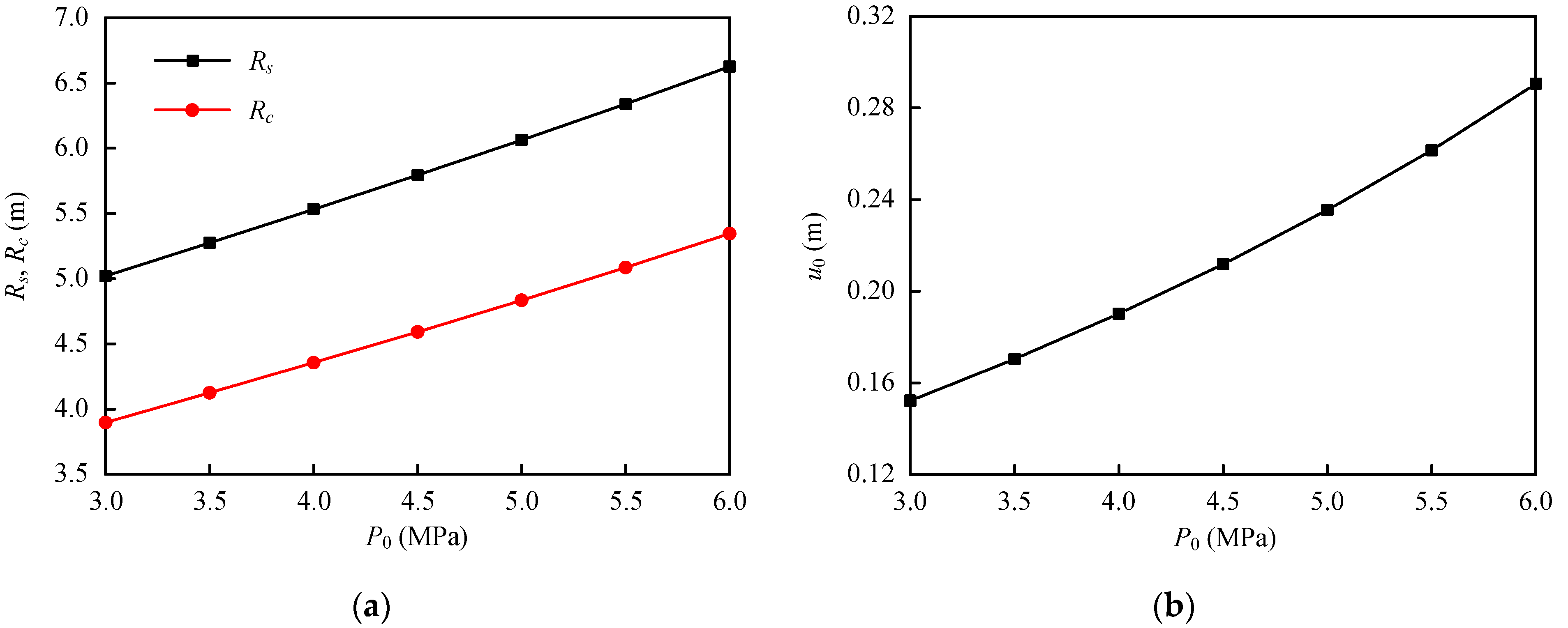
5.1. Seepage Force
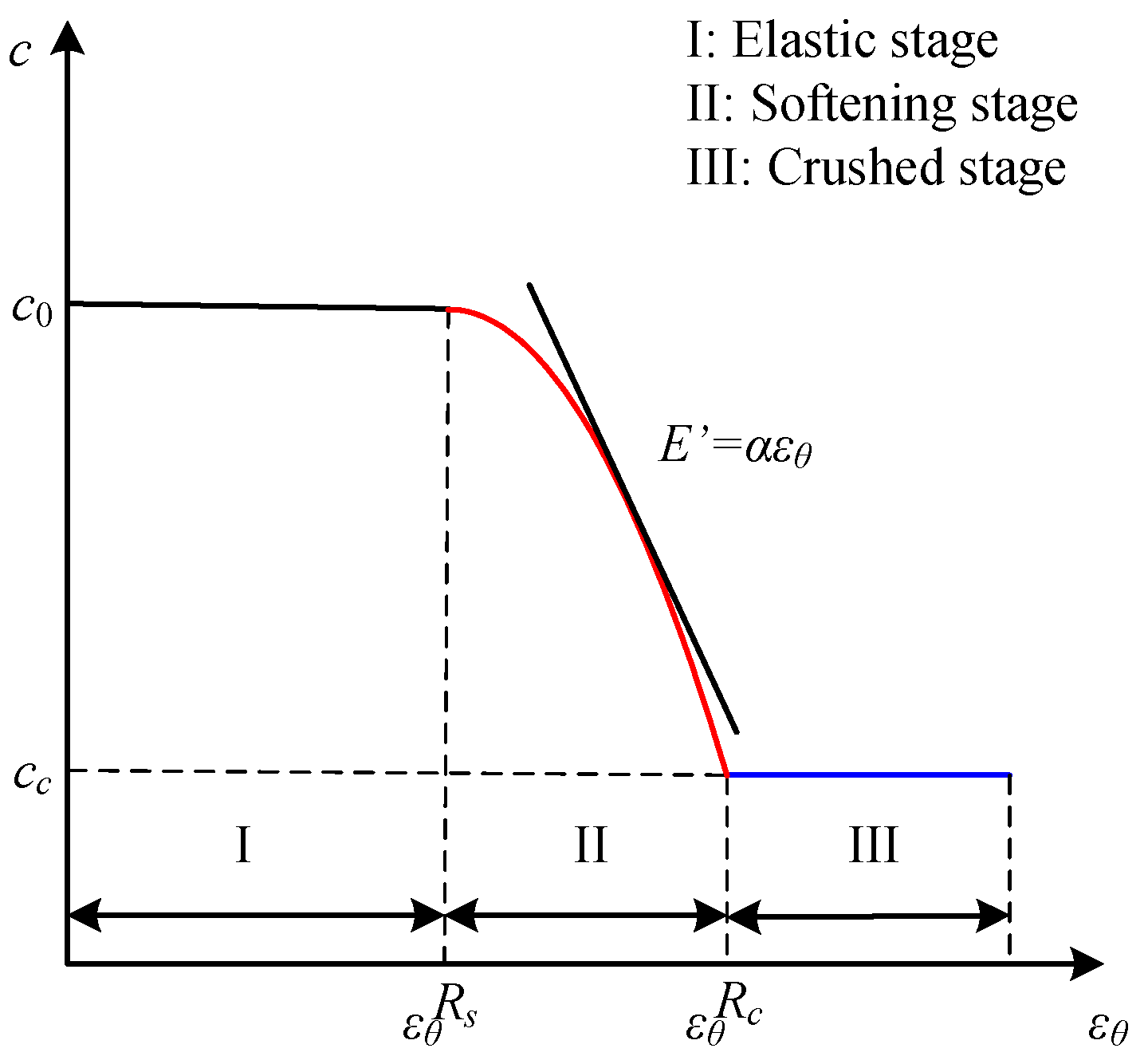
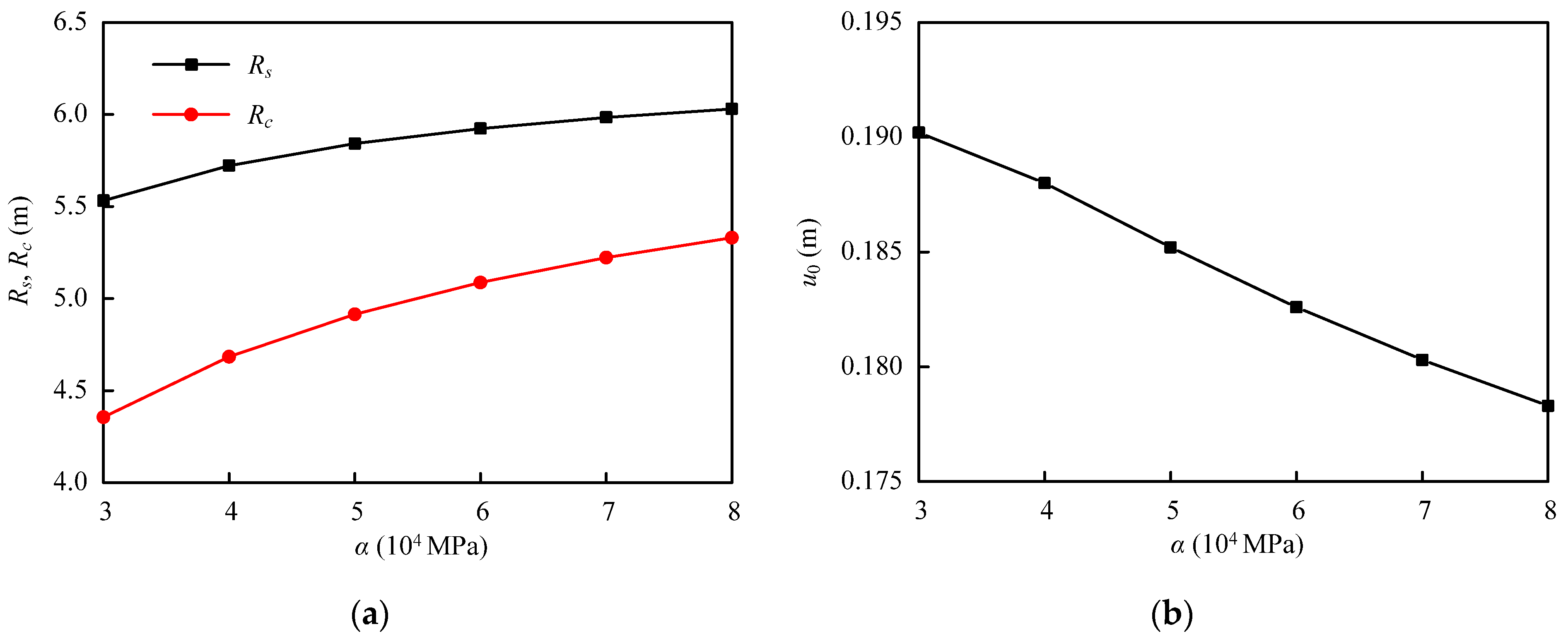
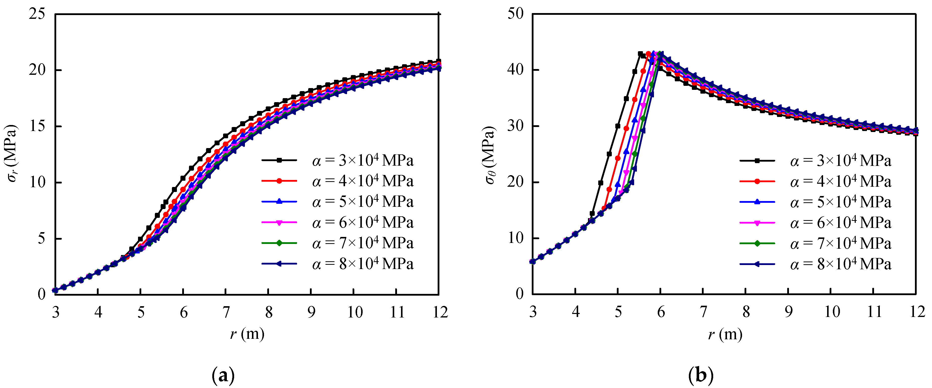
5.2. Softening Modulus Coefficient of Cohesion
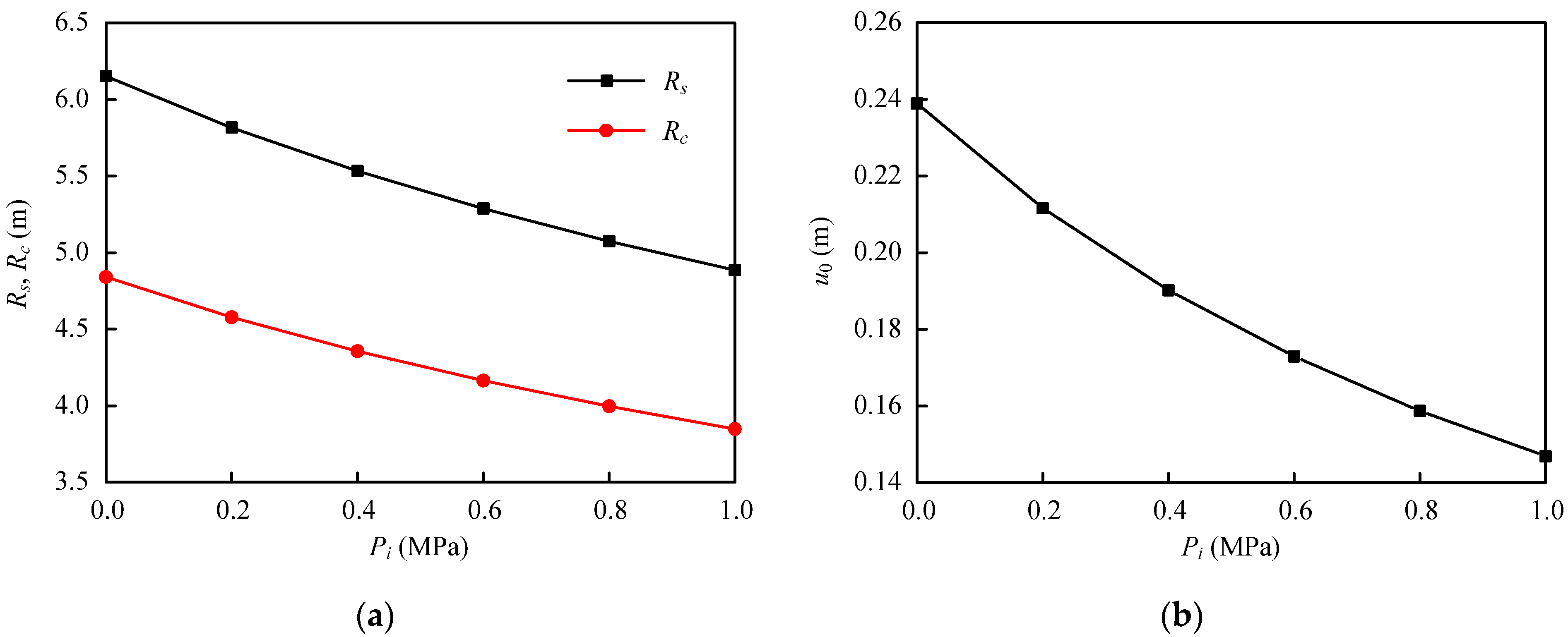
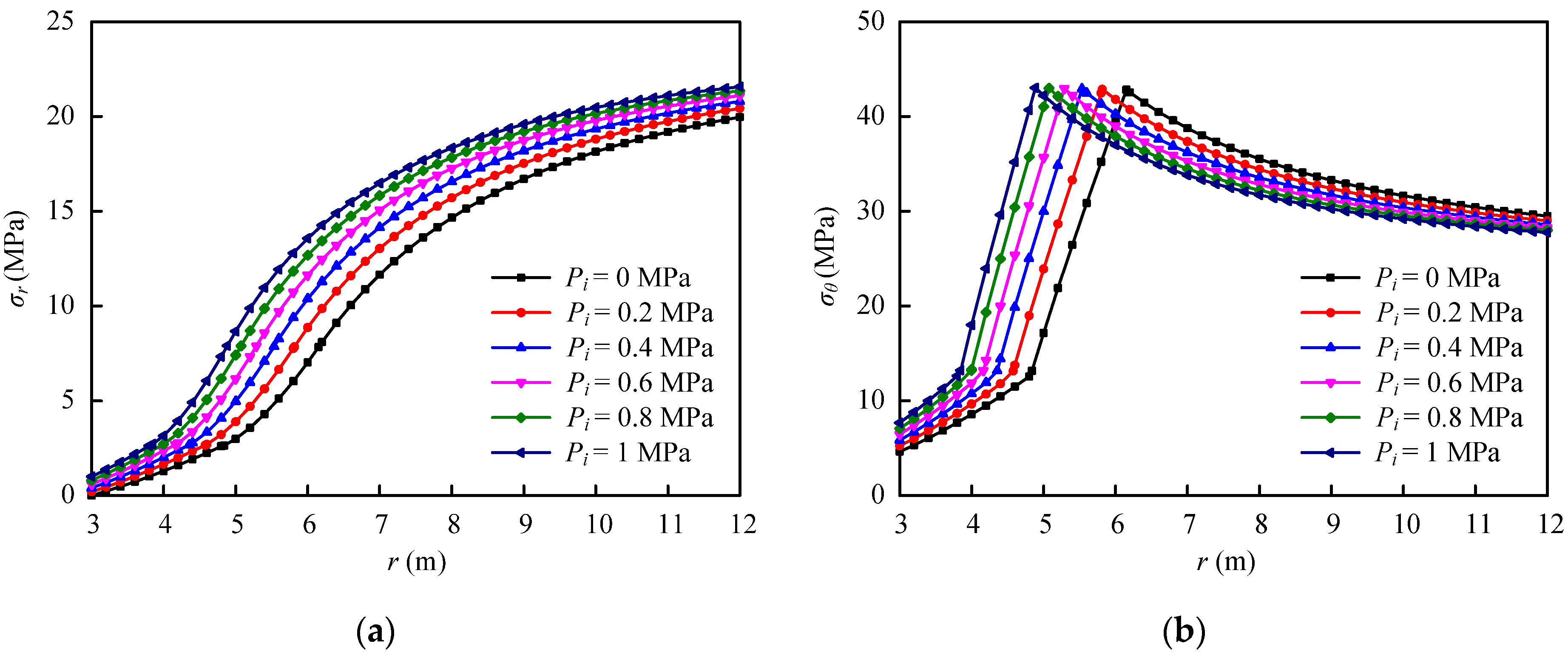
5.3. Initial Support Resistance
6. Conclusions
- (1)
- Compared with other solutions, when the softening modulus coefficient of cohesion and seepage force coefficient are both zero, the current solution degenerates for the elastic–perfectly plastic solution by Kastner. When the softening modulus coefficient of cohesion is large enough, and the seepage force coefficient is zero, the current solution degenerates for the elastic–brittle-plastic solution by Wilson.
- (2)
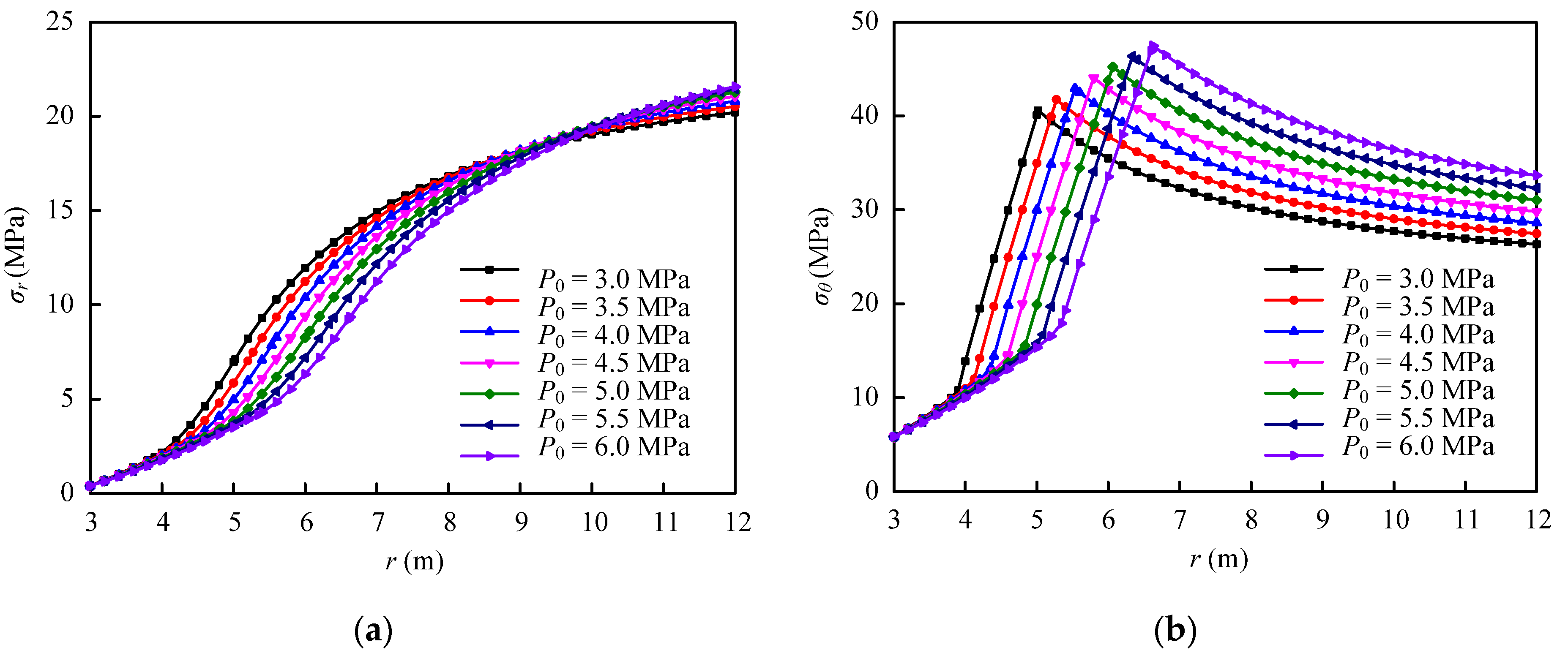
- The tangential stress is always larger than the radial stress. As the distance from the tunnel center increases, the radial stress continues to increase, and the tangential stress first increases in the broken and strain-softening regions and then decreases in the elastic region. The peak value of tangential stress appears at the interface between elastic and strain-softening regions.
- (3)
- As the seepage force increases, the radii of strain-softening and crushed regions and surface displacement all increase. As the softening modulus coefficient of cohesion increases, the radii of strain-softening and crushed regions increase while the surface displacement decreases. Additionally, the radii of strain-softening and crushed regions and surface displacement all decrease with the increasing initial support resistance.
Author Contributions
Funding
Data Availability Statement
Acknowledgments
Conflicts of Interest
References
- Detournay, E. Elastoplastic model of a deep tunnel for a rock with variable dilatancy. Rock Mech. Rock Eng. 1986, 19, 99–108. [Google Scholar] [CrossRef]
- González-Cao, J.; Varas, F.; Bastante, F.G.; Alejano, L.R. Ground reaction curves for circular excavations in non-homogeneous, axisymmetric strain-softening rock masses. J. Rock Mech. Geotech. Eng. 2013, 5, 431–442. [Google Scholar] [CrossRef] [Green Version]
- Luo, Y.; Gong, F.Q.; Zhu, C.Q. Experimental investigation on stress-induced failure in D-shaped hard rock tunnel under water-bearing and true triaxial compression conditions. Bull. Eng. Geol. Environ. 2022, 81, 76. [Google Scholar] [CrossRef]
- Liang, R.Z.; Wu, J.; Sun, L.W.; Shen, W.; Wu, W.B. Performances of adjacent metro structures due to regiond excavation of a large-scale basement in soft ground. Tunn. Undergr. Space Technol. 2021, 117, 104123. [Google Scholar] [CrossRef]
- Tonon, R.C.F. Closed-form solutions for a circular tunnel in elastic-brittle-plastic ground with the original and generalized Hoek–Brown failure criteria. Rock Mech. Rock Eng. 2011, 44, 169–178. [Google Scholar]
- Lv, A.; Masoumi, H.; Walsh, S.D.C.; Roshan, H. Elastic-Softening-Plasticity around a borehole: An analytical and experimental study. Rock Mech. Rock Eng. 2019, 52, 1149–1164. [Google Scholar] [CrossRef]
- Carranza-Torres, C. Elasto-plastic solution of tunnel problem using the generalized form of the Hoek-Brown failure criterion. Int. J. Rock Mech. Min. 2004, 41, 480–481. [Google Scholar] [CrossRef]
- Hao, Y.; Wu, Y.; Mao, X.; Li, P.; Zhang, L.; Tao, J. An elastoplastic softening damage model for hydraulic fracturing in soft coal seams. Adv. Civ. Eng. 2018, 2018, 2548217. [Google Scholar] [CrossRef] [Green Version]
- Park, K.H.; Tontavanich, B.; Lee, J.G. A simple procedure for ground response curve of circular tunnel in elastic-strain softening rock masses. Tunn. Undergr. Space Technol. 2008, 23, 151–159. [Google Scholar] [CrossRef]
- Pourhosseini, O.; Shabanimashcool, M. Development of an elasto-plastic constitutive model for intact rocks. Int. J. Rock Mech. Min. Sci. 2014, 66, 1–12. [Google Scholar] [CrossRef]
- Brown, E.; Bray, J.; Ladanyi, B.; Hoek, E. Ground response curves for rock tunnels. J. Geotech. Eng. 1983, 109, 15–39. [Google Scholar] [CrossRef]
- Masoudian, M.S.; Hashemi, M.A. Analytical solution of a circular opening in an axisymmetric elastic-brittle-plastic swelling rock. J. Nat. Gas Sci. Eng. 2016, 35, 483–496. [Google Scholar] [CrossRef]
- Sharan, S.K. Elastic-brittle-plastic analysis of circular openings in Hoek-Brown media. Int. J. Rock Mech. Min. 2003, 40, 817–824. [Google Scholar] [CrossRef]
- Zareifard, M.; Fahimifar, A. Analytical solutions for the stresses and deformations of deep tunnels in an elastic-brittle-plastic rock mass considering the damaged region. Tunn. Undergr. Space Technol. 2016, 58, 186–196. [Google Scholar] [CrossRef]
- Kastner, H. Statik des Tunnel-Und Stollenbaues; Springer: New York, NY, USA, 1962. [Google Scholar]
- Wilson, A.H. A method of estimating the closure and strength of lining required in drivages surrounded by a yield zone. Int. J. Rock Mech. Min. Geomech. Abstr. 1980, 17, 349–3550. [Google Scholar] [CrossRef]
- Ghorbani, A.; Hasanzadehshooiili, H.; Sadowski, L. Neural prediction of tunnels’ support pressure in elasto-plastic, strain-softening rock mass. App. Sci. 2018, 8, 841. [Google Scholar] [CrossRef] [Green Version]
- Han, J.X.; Li, S.C.; Li, S.C.; Yang, W.M. A procedure of strain-softening model for elasto-plastic analysis of a circular opening considering elasto-plastic coupling. Tunn. Undergr. Space Technol. 2013, 37, 128–134. [Google Scholar] [CrossRef]
- Li, Y.; Cao, S.; Fantuzzi, N.; Liu, Y. Elastoplastic analysis of a circular borehole in elastic-strain softening coal seams. Int. J. Rock Mech. Min. 2015, 80, 316–324. [Google Scholar] [CrossRef]
- Wang, S.L.; Yin, X.T.; Tang, H.; Ge, X. A new approach for analyzing circular tunnel in strain-softening rock masses. Int. J. Rock Mech. Min. 2010, 47, 170–178. [Google Scholar] [CrossRef]
- Jing, W.; Xue, W.; Yao, Z. Variation of the internal friction angle and cohesion of the plastic softening region rock in roadway surrounding rock. J. China Coal Soc. 2018, 43, 2203–2210. [Google Scholar]
- Lu, Y.; Wang, L.; Yang, F.; Li, Y.; Chen, H. Post-peak strain softening mechanical properties of weak rock. Chin. J. Rock Mech. Eng. 2010, 29, 640–648. [Google Scholar]
- Fahimifar, A.; Ghadami, H.; Ahmadvand, M. The influence of seepage and gravitational loads on elastoplastic solution of circular tunnels. Sci. Iran. 2014, 21, 1821–1832. [Google Scholar]
- Fahimifar, A.; Zareifard, M.R. A thoretical solution for analysis of tunnels below groundwater considering the hydraulic-mechanical coupling. Tunn. Undergr. Space Technol. 2009, 24, 634–646. [Google Scholar] [CrossRef]
- Huangfu, M.; Wang, M.S.; Tan, Z.S.; Wang, X.Y. Analytical solution for steady seepage into an underwater circular tunnel. Tunn. Undergr. Space Technol. 2010, 25, 391–396. [Google Scholar] [CrossRef]
- Fan, H.; Wang, L.G.; Wang, S.; Jiang, C.Y. A new unified solution for deep tunnels in water-rich areas considering seepage force. Geofluids 2021, 2021, 6696757. [Google Scholar] [CrossRef]
- Mogi, K. Flow and fracture of rocks under general triaxial compression. Appl. Math. Mech. 1981, 2, 635–651. [Google Scholar] [CrossRef]


Disclaimer/Publisher’s Note: The statements, opinions and data contained in all publications are solely those of the individual author(s) and contributor(s) and not of MDPI and/or the editor(s). MDPI and/or the editor(s) disclaim responsibility for any injury to people or property resulting from any ideas, methods, instructions or products referred to in the content. |
© 2023 by the authors. Licensee MDPI, Basel, Switzerland. This article is an open access article distributed under the terms and conditions of the Creative Commons Attribution (CC BY) license (https://creativecommons.org/licenses/by/4.0/).
Share and Cite
Fan, H.; Wang, L.; Li, S. A New Approach for Analyzing Circular Tunnels in Nonlinear Strain-Softening Rock Masses Considering Seepage Force. Minerals 2023, 13, 138. https://doi.org/10.3390/min13020138
Fan H, Wang L, Li S. A New Approach for Analyzing Circular Tunnels in Nonlinear Strain-Softening Rock Masses Considering Seepage Force. Minerals. 2023; 13(2):138. https://doi.org/10.3390/min13020138
Chicago/Turabian StyleFan, Hao, Lei Wang, and Shaobo Li. 2023. "A New Approach for Analyzing Circular Tunnels in Nonlinear Strain-Softening Rock Masses Considering Seepage Force" Minerals 13, no. 2: 138. https://doi.org/10.3390/min13020138