Article

Fault Diagnosis of Crack on Gearbox Using Vibration-Based Approaches

1
Department of Mechanical Engineering, College of Engineering, University of Mosul, Mosul 41002, Iraq
2
Department of Mechanical Engineering, Faculty of Engineering, South Valley University, Qena 83523, Egypt
3
Department of Physics and Engineering, Frostburg State University, Frostburg, MD 21532, USA
*
Author to whom correspondence should be addressed.
Symmetry 2022, 14(2), 417; https://doi.org/10.3390/sym14020417
Submission received: 1 July 2021 / Revised: 22 December 2021 / Accepted: 24 January 2022 / Published: 19 February 2022
(This article belongs to the Special Issue Solid Mechanics and Mechanical Mechanics)

Abstract

:
This study experimentally investigates vibration-based approaches for fault diagnosis of automotive gearboxes. The primary objective is to identify methods that can detect gear-tooth cracks, a common fault in gearboxes. Vibrational signals were supervised on a gearbox test rig under different operating conditions of gears with three symmetrical crack depths (1, 2, and 3 mm). The severity of the gear-tooth cracks was predicted from the vibrational signal dataset using an artificial feedforward multilayer neural network with backpropagation (NNBP). The vibration amplitudes were the greatest when the crack size in the high-speed shaft was 3 mm, and the root mean square of its vibration speed was below 3.5 mm/s. The vibration amplitudes of the gearbox increased with increasing depth of the tooth cracks under different operating conditions. The NNBP predicted the states of gear-tooth cracks with an average recognition rate of 80.41% under different conditions. In some cases, the fault degree was difficult to estimate via time-domain analysis as the vibration level increases were small and not easily noticed. Results also showed that when using the same statistical features, the time-domain analysis can better detect crack degree compared to the neural network technique.

1. Introduction

In advanced machinery, the gearbox transmits the required power or motion to the device of the application. Any malfunction of the gearbox parts degrades the efficiency and productivity of the system. Gears are responsible for many common machine breakdowns that lead to improper operating conditions and failure of the entire mechanism [1]. Gearboxes are widely used in automotive, manufacturing, and railway applications. Fault diagnosis of the gearbox considerably reduces the total cost of maintenance. Various faults could occur within the gearbox due to inadequate lubrication, excessive applied load, decoupling, misalignment, poor cooling, improper gear design, and others [2].
The gear system is a vital subsystem of any machinery tool, and gear cracking is the most important issue of the failure mode. The gearing operation majorly relies on the durability of the tooth conditions. Link et al. [3] reported that gear failures contribute to approximately 59% of the failure modes in wind turbines. Astridge [4] reported that approximately 19.1% of all transmission-system failures are attributable to gear failures. Yin et al. reported that crack propagation diminishes the lifetime of the machinery [5]. Aslantaş and Taşgetiren [6] simulated the crack propagation path on a gear-tooth surface and compared their simulated results with those obtained experimentally to detect the pitting formation life.
Recently, the vibration signals of faulty parts have been used for fault detection [7]. Ma et al. [8] considered the vibration features of a gear pair with spalling faults, which are fundamental to fault diagnosis and identification of the spalling mechanism. They estimated the time-varying mesh stiffness for many crack lengths and crack paths and detected the vibration signatures of cracked gears using the suggested model. Recently, Shalaan et al. [9] found that vibration signals are crucial in the evaluation of gearbox defects. Moreover, the highest peak value in the time domain fluctuates around the x-axis and increases with gear speed.
During the past three decades, diagnostic techniques for the detection of gearbox defects have been intensively researched, including those reported by Dalpiaz et al. [10], Ma et al. [11], Mohammed et al. [12], Saxena et al. [13], Wu et al. [14], and Li [15]. Rezaei et al. [16] detected multicrack locations and lengths from transmission-error ratios. In solved examples, they showed that when the cracks are sufficiently far, their effects on the transmission error are clearly distinguishable, and their lengths can be observed precisely. Gritli et al. [17] diagnosed the faults resulting from tooth root cracks in a gear pair. Finite element analysis and dynamic simulations of the gear system performed in MATLAB software can obtain the mesh stiffness of a gear pair. The modulation created more sidebands than that of a normal gear with healthy teeth.
Belsak and Flasker [18] examined gear-tooth cracks in time and frequency domains under healthy and defect conditions. Combet et al. [19] experimentally monitored the vibration signals of a cracked gear to validate their simulation results. They observed that their diagnostic approach depended on the angle within a specific frequency range. They measured the damage degree of cracked teeth using the root mean square and kurtosis degree. Furthermore, they analyzed the fault features of a gear system with crack and tooth fracture faults. The amplitude of the meshing frequency was found to increase with crack length.
Artificial neural networks (ANNs) are commonly employed in fault diagnosis. Examples of ANN-based studies are those by Ghazaly et al. [20], who detected misfires in a spark-ignition engine, and Kumar et al. [21], who monitored the condition of rolling element bearings. Tosun et al. [22] predicted engine characteristics via linear regression and ANN modeling. When trained and tested on the data obtained from experimental studies, ANNs can accurately predict the fault parameters. For instance, Tosun et al. [22] demonstrated that an ANN efficiently predicts the failure load in single-lap adhesive joints under tensile loading. Ghazaly et al. [20] found combustion faults in an internal combustion engine using an ANN and the wavelet packet transform.
Figure 1 and Figure 2 show two examples of the proposed method. A gearbox of lathe machine and drilling machine. The machines are used in various applications. It is essential to early detect gears faults and bearings faults inside these rotating machines before they exaggerate into higher degrees of faults and propagate through interfering systems resulting in machine failures or even causalities.
Herein, several sets of gears were experimentally tested at different speeds on a gearbox test rig. The healthy gears were fastened inside the gearbox casing, and their vibration signals were collected by data acquisition systems for affording healthy baseline characteristics. The healthy gears were then replaced with cracked gears with symmetrical crack depths (1, 2, and 3 mm), and the vibration signals in each case were separately collected under the same conditions. The defect signals in the gears were identified using different approaches: time domain, frequency domain, crest factor, kurtosis, and root mean square. The results obtained from the analysis of the faulty gears were compared with those obtained from gears with healthy teeth. The time-domain analysis used in the feature extraction was input to the network, and the defect signals of the gears were analyzed using the crest factor, kurtosis, peak, and root mean square. The recognition rate was then summarized in each state. This is an important topic when it comes to designing gears for different applications as vibration detection, fault, and signature are great measures of gears performance. The work fits the aim of symmetry as it provides readers with information about the current and latest advancement in this area.

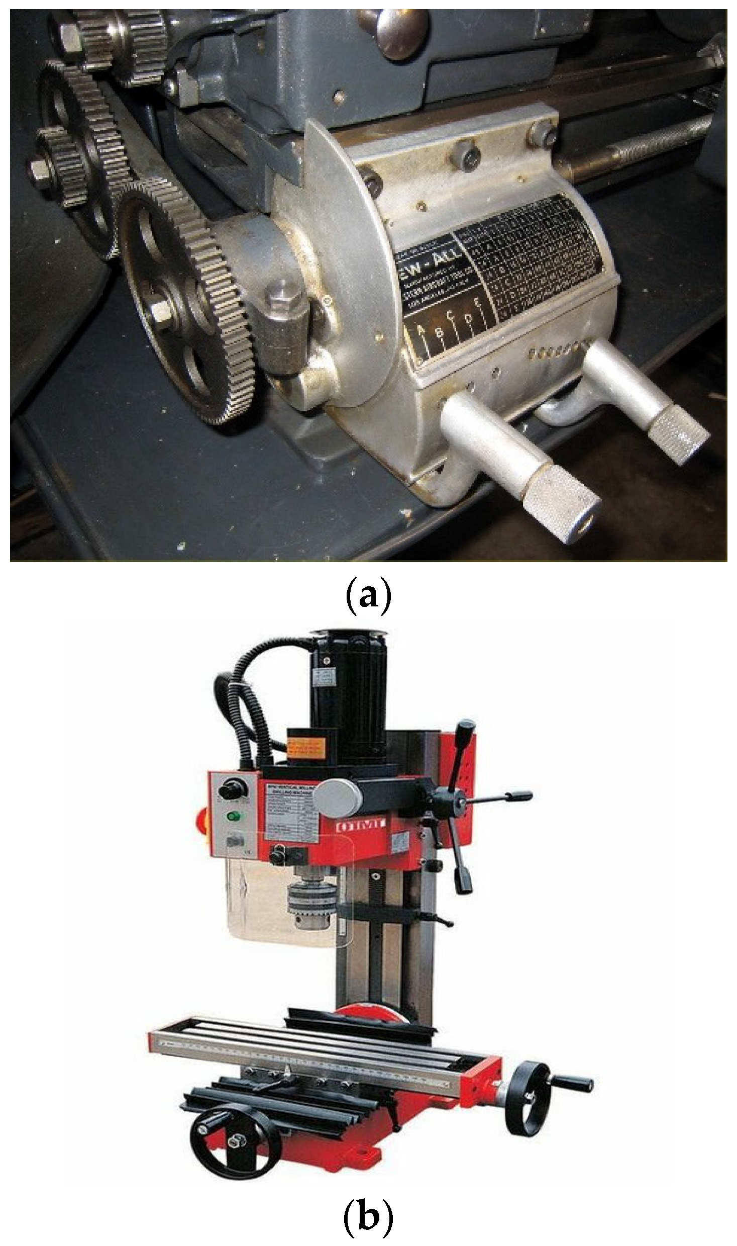
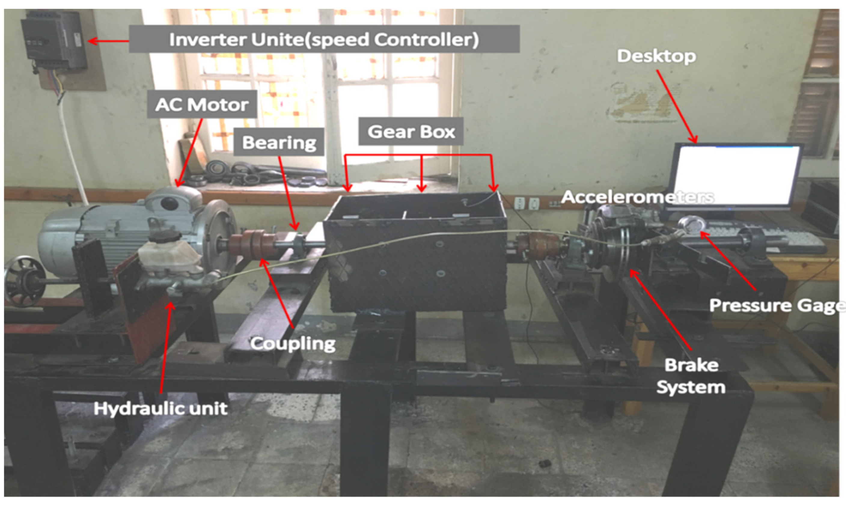
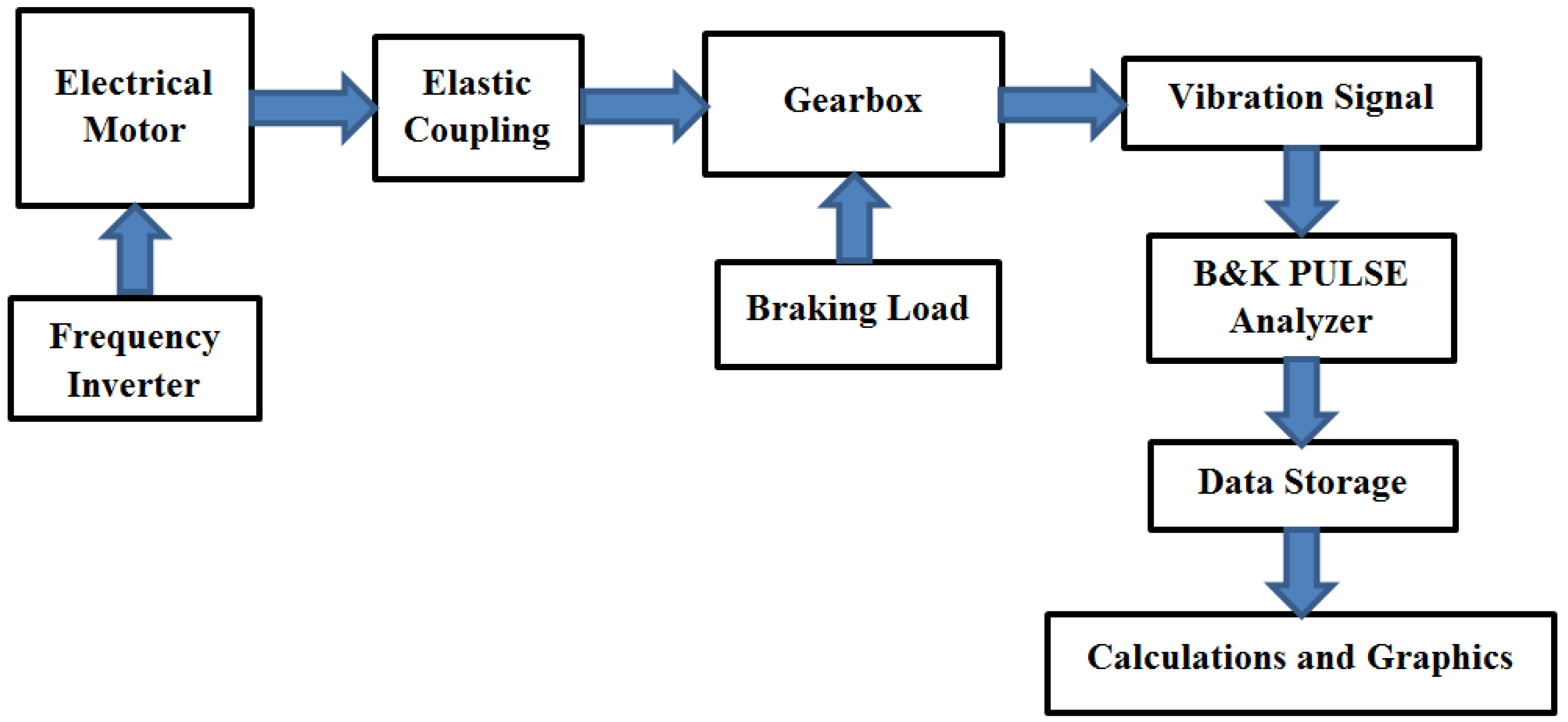
2. Experimental Test Rig

The faults in the gearbox were detected and analyzed in an experimental gearbox setup (see Figure 1). The data were sufficiently accurate and abundant to be evaluated via complex signal-processing techniques. The primary objective of these experimental studies was to monitor the conditions of healthy and cracked gearboxes operating under different applied loads and operating speeds. The experimental facility was developed to obtain the vibration signatures of gearboxes. The driving unit comprised a 7.5-kW AC motor with a maximum speed of 1500 rpm and a three-phase frequency inverter that rotated the driving shaft at different rotational speeds. The disc brake assembly was connected directly to the electrical motor. The braking unit comprised a hydraulic system that applied the required load to the brake system. The pressure value was controlled by a hydraulic valve and displayed on a pressure gauge. The vibration data were provided by a piezoelectric accelerometer with a sensitivity of 100 mV/g, which was directly waxed and placed on the casing near the selected gear to ensure the accuracy of the data. The measured signals were sent to the dual-channel analyzer and saved as vibration signatures. The time-domain signals were acquired under several operating conditions. The stored data in the vibration analyzer were retrieved through a cable connected to the computer for further analysis using PULSE software. A MATLAB code was utilized for training the ANN. More details are provided in the block diagram of the gearbox test rig (see Figure 2).
Figure 3 shows a block diagram of the gearbox test rig. The electrical motor speed is controlled by an inverter unit. The output shaft of the motor is coupled with the input shaft of the gearbox. The braking unit uses a hydraulic system to provide the required load to the output shaft through the gearbox. The output shaft of the gearbox is controlled by a hydraulic disc brake unit. The vibration signals are collected using the accelerometer and stored in a PC using Bruel and Kjaer Data acquisition device (analyzer). Finally, features are extracted from the raw time-domain signal, stored, and analyzed.
Table 1 shows data acquisition device specifications and parameters used in the experiments.

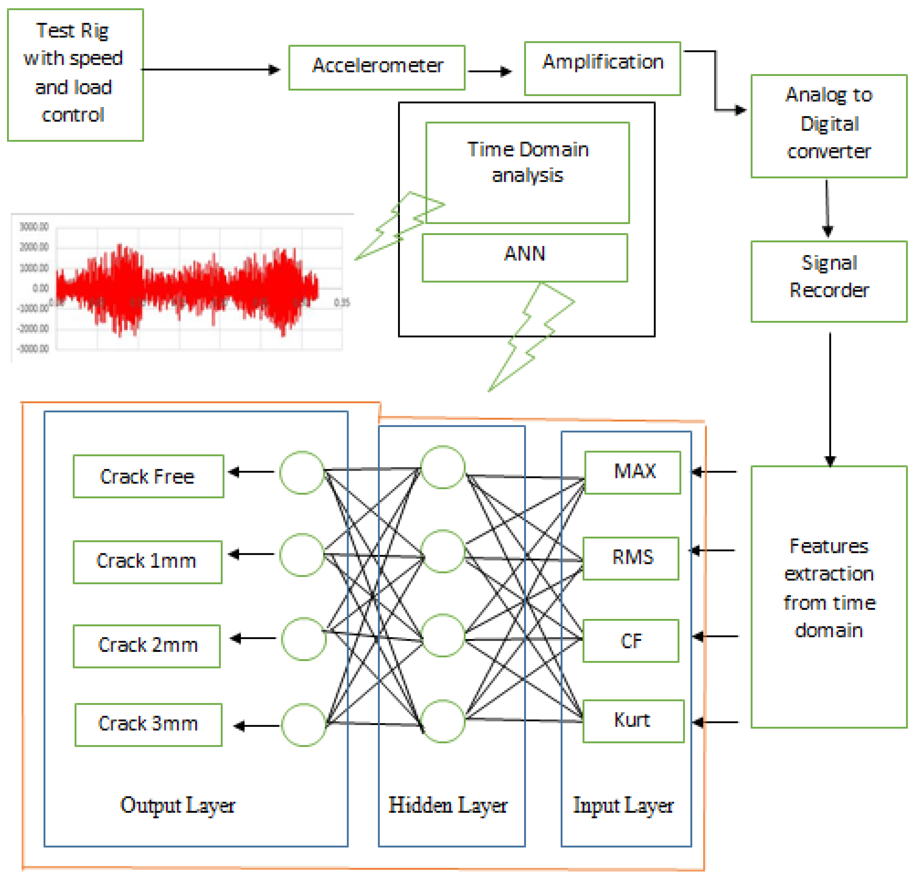
3. Time-Domain Analysis and Features Extraction

Faulty conditions were determined based on the signal features extracted using signal-processing techniques (such as time analysis) and statistical parameters of the signals (mean, variance, standard deviation, kurtosis, root mean square, crest factor, maximum, minimum, mode, and median). These features of the statistical parameters can describe the trend of gearbox faults. The maximum and minimum may not only seem to provide similar information but are also useful for notifying the range (upper and lower limit values in the network).
The kurtosis indicates the impulsiveness of the signal. It is expressed as
k u t o s i s = I = 1 N ( x i x ¯ ) 4 N S 4
The information from the root mean square (RMS) differs from that of the mean; the mean denotes the center of the dispersed data, whereas the RMS is important when the values range between positive and negative (such as sinusoids). The RMS is used in the calculation of the crest factor of a time-domain analysis:
R M S = i = 1 N ( x i ) 2 N
The crest factor is determined as
c r e s t   f a c t o r = x m a x R M S
where x i is a data point in the sample, N is the sample size, x ¯ is the mean, and S is the standard deviation.
The crest factor is defined as the maximum peak value of the vibration signal x over a period of measured time divided by the RMS of the vibration signal.
The severity of the defect is calculated to distinguish crack degree. The crack severity is calculated using Equations (4)–(7):
S p = Crack   Peak CrackFree   Peak
S RMS = Crack   RMS CrackFree   RMS
S CF = Crack   CF CrackFree   CF
S Kurt = Crack   KURT CrackFree   KURT
where S p , S RMS , S CF , and S Kurt are crack severity calculated from peak, root mean square, crest factor, and kurtosis, respectively.
In the time-domain statistical feature analysis, 60 instances were randomly selected from 75 instances cases. The remaining 15 instances were reserved for validation and correctness. In all experiments, five operating speeds and five loads were selected.

4. Artificial Neural Network Training

ANNs mimic the neural system in the human brain. A biological neuron takes an input, performs calculations in its processing unit, and outputs the result. The hidden layer in the neuron (unlike the input and output layers) does not interact with the environment. A typical biological neuron is shown in Figure 3. ANN is considered an important technique in machine learning and artificial intelligence and has considerably improved the performance of fault detection. The interconnected processing units in an ANN are highly simplified models of those in real biological neural networks. ANNs can solve complicated engineering problems without requiring complex rules and mathematical formulations; instead, they learn the key information patterns within a multi-information domain.
In the present application, the classification task must recognize the patterns of gear-tooth cracks. The dataset comprised 200 samples divided into four states (50 observations of each label-targeted state: crack-free, 1-mm, 2-mm, and 3-mm cracks). Seventy percent (140 of 200 samples) of the data were randomly selected for the training network, 15% (30 samples) were reserved for validating the network, and the final 15% (30 samples) were used for testing the network subsequent to training. During validation, the weights were adjusted until there was no need to update the network connections. The number of hidden neurons was four. The training function (learning algorithm) used was the simple gradient descent method, and the error method used for backpropagation was the mean square error.

5. Experimental Procedure

Prior to conducting the experiment, the gearbox test rig vibrations were measured and verified to assess their ovality and misalignment. The experimental test was executed for 15 min to ensure a steady-state system. An accelerometer with a magnetic base was mounted directly over the bearing support to acquire the vibration signals. The output signal was collected from the accelerometer and fed into the dual-channel vibration analyzer. The time-domain information was acquired at different operating speeds under different applied loads. The stored data were retrieved and passed through a cable to the computer for analysis using PULSE software. After obtaining the necessary signatures of the system with the healthy gear, the healthy gear was replaced with a defective gear that had a specific crack size, and the experimental tests were then repeated under the abovementioned conditions. Figure 4 is a flowchart of the research methodology used herein, and Figure 5 illustrates a healthy and defective helical gear. The vibration events were recorded at five speeds (600, 700, 800, 900, and 1000 rpm) and five load capacities (0%, 25%, 50%, 75%, and 100%).
In real-world applications, accelerometers measure the complex voltage waveforms, and their time-domain signals provide a detailed understanding of the vibration patterns and events. In this experiment, the time-domain signals were collected and the statistical features fed into the ANN were extracted using the traditional time-domain technique. The vibration signal is recorded using Bruel and Kjaer accelerometer. The network was a simple feedforward backpropagation network trained using the gradient descent method, and its performance measure was the mean square error.

6. Results and Discussions

Cracks in the gear teeth were detected using a vibration-based technique. The results of three crack sizes (1, 2, and 3 mm) were compared with those of the healthy case at five shaft-rotation speeds (600, 700, 800, 900, and 1000 rpm) under 0%, 25%, 50%, 75%, or 100% load. All vibration measurements were obtained under the same operational conditions, and dry friction was assumed. Figure 6 compares the RMS values of the systems with different symmetrical crack depths (including the healthy condition with crack depth = 0 mm). The maximum amplitude of the vibration signature reflected the intensity of the defect in the system. Specifically, the maximum amplitude of the vibration increased with the symmetrical crack depth of the teeth.
As seen from the crest factors in Figure 6, the maximum amplitude of the vibration signature reflects the intensity of the defect in the system. The maximum amplitude of vibration was an increasing function of the symmetrical crack depth. Identical results were obtained from the kurtosis analysis. From the experimental results at a given operating time, it was observed that the greater the applied running speed, the greater the RMS, and the greater were the maximum and average values of the signals.
Figure 6 Regular time-domain analysis results at different speeds (left to right blocks: 600, 700, 800, 900, 1000 rpm) under different load capacities (left to right bars in each block: 0%, 25%, 50%, 75%, 100%). From top to bottom are plotted the peak (max), root mean square (RMS), crest factor = peak/RMS, and kurtosis.
As evidenced in Figure 6, increasing the severity of the fault increased the values of the statistical features up to load capacities of 50–75%. At higher load capacities, the values tended to decrease. One can thus conclude that although the threshold for fault detection is determinable, it cannot be generalized because the behavior differs under different speed and load-capacity conditions.
Table 2 shows the crack severities boundaries using equation 4 of 60 instances under different operating conditions. The severity is the ratio between the statistical feature extracted from the crack signal and the statistical feature extracted from the crack-free signal. The results indicate that the crack degree boundaries can be determined using the size of the crack.
Table 3 illustrates the validation of the 15 instances that were not involved in obtaining the results in Table 1. Passed statistical features are defined as how many features severities passed the test using the information provided in Table 1. Table 3 shows that at 1 mm crack size, the first two instances (75%) failed to pass the statistical features, and the other three instances passed the statistical features. The result also shows that five instances passed the statistical features of tests conducted on 2 mm and 3 mm crack sizes under shown speed and load conditions.
Table 4 shows a mix-up evaluation of crack severities of five instances used to validate each of the three degrees of crack. The results show that all real cracks were predicted as expected, which means that there is no misclassification.
Table 5 lists the recognition rates (percentages) of the different classes in the ANN. By discerning the fault degree, the ANN can isolate different crack depths under different load and speed conditions. When the recognition rate was 100%, the ANN correctly classified the fault in all instances. Thus, the pattern recognition performance of the network is optimal at higher speeds and under half-load capacities.
Table 6 shows the average recognition rates of four cases: crack-free and cracks with 1, 2, and 3 mm depth. The average recognition rate is defined as the average of recognition rates for all different cases at five speeds and five loads, as illustrated in Table 5. Damages are detected irrespective of the transmitted power and rotational speed. The results indicate that the ANN with fed features could discern healthy condition (crack free) by 78.8%, 78.24% with 1 mm crack depth, 75.8% with crack 2 mm crack depth, and 89.76% with 3 mm crack depth 3 mm on average when compared to the networks shown in Table 5.
Table 7 provides a comparison between the proposed method and the other two methods: Novel convolution neural network (NCNN) [21] and Convolution neural network (CNN) [22]. The proposed method provides a much simpler technique while it has an accuracy of 80.65%. Table 7 also provides a summary of features, operating conditions, and application of the three methods.

7. Conclusions

This study performed a crack-fault diagnosis of helical gears and analyzed them based on their vibrational amplitudes under different operating-speed conditions. The vibration signatures of healthy and cracked gears were obtained in an experimental facility under different operating conditions. The experimental results confirmed that vibration signal analysis is crucial in the evaluation of gearbox crack defects. The statistical parameters (RMS, crest factor, and kurtosis) of the systems with healthy and defective gears significantly depended on their operating speeds. Moreover, increasing the depth of the defect increased the vibration generation of the gearbox. The vibration amplitudes increased with symmetrical crack depth in gears running at different speeds.
Moreover, the results showed that the time-domain analysis is a better ANN method in detecting the sizes of the cracks. This is due to adopting simpler and fewer requirements than ANN. The ANN requires large datasets to raise the model accuracy. The average recognition rate for detection of 1 mm crack using the ANN method was 78.8% and 90% using the time-domain analysis. These results indicate that the time-domain analysis improved the results by 11.2% compared to using the ANN method. The severity calculation with the help of time-domain signature could be an indication of detecting gear crack degree using vibration measurement. It is recommended to compare these methods using different faults with larger data samples and other statistical features. Finally, it is recommended to train the ANN using the data collected at higher speeds and half-load capacities to maximize the recognition performance of gear-crack detection.

Author Contributions

Conceptualization, S.A.M. and N.M.G.; methodology, S.A.M.; software, N.M.G.; validation, S.A.M., N.M.G. and J.A.; formal analysis, J.A.; investigation, S.A.M.; resources, N.M.G.; data curation, N.M.G.; writing—original draft preparation, S.A.M.; writing—review and editing, J.A.; visualization, N.M.G.; supervision, J.A.; project administration, N.M.G.; funding acquisition, S.A.M. All authors have read and agreed to the published version of the manuscript.

Funding

This research received no external funding.

Institutional Review Board Statement

Not applicable.

Informed Consent Statement

Not applicable.

Data Availability Statement

The study didn’t report any data.

Conflicts of Interest

The authors declare no conflict of interest.

References

  1. Chen, P.; Zhao, X.; Jiang, H. A New Method of Fault Feature Extraction Based on Hierarchical Dispersion Entropy. Shock Vib. 2021, 2021, 8824901. [Google Scholar] [CrossRef]
  2. Xu, J.; Xu, P.; Wei, Z.; Ding, X.; Shi, L. DC-NNMN: Across Components Fault Diagnosis Based on Deep Few-Shot Learning. Shock Vib. 2020, 2020, 3152174. [Google Scholar] [CrossRef]
  3. Yuan, Z.; Zhou, T.; Liu, J.; Zhang, C.; Liu, Y. Fault Diagnosis Approach for Rotating Machinery Based on Feature Importance Ranking and Selection. Shock Vib. 2021, 2021, 8899188. [Google Scholar] [CrossRef]
  4. Zhang, D.; Ren, X.; Zuo, H. Compound Fault Diagnosis for Gearbox Based Using of Euclidean Matrix Sample Entropy and One-Dimensional Convolutional Neural Network. Shock Vib. 2021, 2021, 6669006. [Google Scholar] [CrossRef]
  5. Long, Y.; Shi, X.; Chen, Q.; Xiao, Z.; Qin, Y.; Lv, J. Early Fault Diagnosis Technology for Bearings Based on Quantile Multiscale Permutation Entropy. Math. Probl. Eng. 2021, 2021, 7718074. [Google Scholar] [CrossRef]
  6. You, D.; Chen, L.; Liu, F.; Zhang, Y.; Shang, W.; Hu, Y.; Liu, W. Intelligent Fault Diagnosis of Bearing Based on Convolutional Neural Network and Bidirectional Long Short-Term Memory. Shock Vib. 2021, 2021, 7346352. [Google Scholar] [CrossRef]
  7. Xu, Z.; Li, X.; Wang, J.; Wang, Z. Reliable Fault Diagnosis of Rolling Bearing Based on Ensemble Modified Deep Metric Learning. Shock Vib. 2021, 2021, 5153751. [Google Scholar] [CrossRef]
  8. Mohamad, S.A.; Makrahy, M.M.; Ghazaly, N.M. Fault Diagnosis of Helical Gear through Various Vibration Techniques in Automotive Gearbox. J. Mech. Des. Vib. 2019, 7, 21–26. [Google Scholar]
  9. Ghazali, M.H.M.; Rahiman, W. Vibration Analysis for Machine Monitoring and Diagnosis: A Systematic Review. Shock Vib. 2021, 2021, 9469318. [Google Scholar] [CrossRef]
  10. Zhang, X.; Cong, Y.; Yuan, Z.; Zhang, T.; Bai, X. Early Fault Detection Method of Rolling Bearing Based on MCNN and GRU Network with an Attention Mechanism. Shock Vib. 2021, 2021, 6660243. [Google Scholar] [CrossRef]
  11. He, J.; Li, X.; Chen, Y.; Chen, D.; Guo, J.; Zhou, Y. Deep Transfer Learning Method Based on 1D-CNN for Bearing Fault Diagnosis. Shock Vib. 2021, 2021, 6687331. [Google Scholar] [CrossRef]
  12. Chen, Y.; Yuan, J.; Luo, Y.; Zhang, W. Fault Prediction of Centrifugal Pump Based on Improved KNN. Shock Vib. 2021, 2021, 7306131. [Google Scholar] [CrossRef]
  13. Shu, L.; Shen, J.; Liu, X. Fault Diagnosis Method for Rotating Machinery Based on Hierarchical Amplitude-Aware Permutation Entropy and Pairwise Feature Proximity. Shock Vib. 2021, 2021, 4395500. [Google Scholar] [CrossRef]
  14. Ghazaly, N.M.; Abdel-Fattah, M.; Makrahy, M.M. Determination of Engine Misfire Location using Artificial Neural Networks. Int. J. Veh. Struct. Syst. 2019, 11, 407–412. [Google Scholar] [CrossRef]
  15. Zhang, Y.; He, L.; Cheng, G. A Vibrational Signal Fault Diagnosis Rule Extraction Method Based on DST-ACI Discriminant Criterion. Shock Vib. 2021, 2021, 8085421. [Google Scholar] [CrossRef]
  16. Chen, J.; Xu, B.; Zhang, X. A Vibration Feature Extraction Method Based on Time-Domain Dimensional Parameters and Mahalanobis Distance. Math. Probl. Eng. 2021, 2021, 2498178. [Google Scholar] [CrossRef]
  17. Ren, Q.; Kou, Z.; Wu, J.; Li, T.; Yahya, W. Development and Parametric Analysis of Vibration System Controlled by Hydraulic Shock Rotary Vibrator. Shock Vib. 2021, 2021, 1082963. [Google Scholar] [CrossRef]
  18. Miao, F.; Zhao, R.; Jia, L.; Wang, X. Multisource Fault Signal Separation of Rotating Machinery Based on Wavelet Packet and Fast Independent Component Analysis. Int. J. Rotating Mach. 2021, 2021, 9914724. [Google Scholar] [CrossRef]
  19. Kou, F.; Wu, J.; Gao, J.; Wu, D.; Chen, R. Active Fault-Tolerant Control Based on the Fault of Electromagnetic Hybrid Active Suspension. Shock Vib. 2021, 2021, 4273698. [Google Scholar] [CrossRef]
  20. Yang, Z.; Ying, S.; Wang, B.; Li, Y.; Dong, B.; Geng, J.; Zhang, T. A System Fault Diagnosis Method with a Reclustering Algorithm. Sci. Program. 2021, 2021, 6617882. [Google Scholar] [CrossRef]
  21. Kumar, A.; Vashishtha, G.; Gandhi, C.P.; Zhou, Y.; Glowacz, A.; Xiang, J. Novel Convolutional Neural Network (NCNN) for the Diagnosis of Bearing Defects in Rotary Machinery. IEEE Trans. Instrum. Meas. 2021, 70, 1–10. [Google Scholar] [CrossRef]
  22. Pham, M.T.; Kim, J.-M.; Kim, C.H. Intelligent Fault Diagnosis Method Using Acoustic Emission Signals for Bearings under Complex Working Conditions. Appl. Sci. 2020, 10, 7068. [Google Scholar] [CrossRef]
Figure 1. Examples of method 2: (a) Lathe machine headstock gearbox, (b) drilling machine.
Symmetry 14 00417 g001
Figure 2. Photograph of the gearbox test rig.
Symmetry 14 00417 g002
Figure 3. Block diagram of the gearbox test rig.
Symmetry 14 00417 g003
Figure 4. Flowchart of the methodology used herein.
Symmetry 14 00417 g004
Figure 5. (A) Healthy helical gear, (B) defective helical gear.
Symmetry 14 00417 g005
Figure 6. (a) Time-domain peak feature. (b) Time-domain root mean square feature. (c) Time-domain crest factor feature. (d) Time-domain kurtosis feature.
Symmetry 14 00417 g006aSymmetry 14 00417 g006b
Table 1. Data acquisition device.
3560-B-130 (Bruel and Kjaer)
Channels 5-input channels
Input type Direct/CCLD, 1 Tacho conditioning
Frequency range 0 Hz to 25,600 Hz
Communication to PC LAN interface
Voltage 10–32 V DC
Digital signal size 13 Bits
Sampling Frequency (Hz)12,500
Number of data points8192
Sampling period (seconds per
sample)
0.00008
Duration of samples (s)0.655
FilterAnti-aliasing filter (analog)
Finite Impulsive Response (FIR)
Band-pass digital filter (10–25 kHz)
Table 2. Crack Severities boundary.
Degree of CrackSeverityMore ThanLess Than or Equal
1 mmPeak Severity11.27
Root mean square Severity1.0131.10
Crest Factor Severity0.901.23
Kurtosis Severity0.523.04
2 mmPeak Severity1.382.00
Root mean square Severity1.481.55
Crest Factor Severity0.921.29
Kurtosis Severity0.833.23
3 mmPeak Severity1.642.24
Root mean square Severity1.791.87
Crest Factor Severity0.901.20
Kurtosis Severity0.763.15
Table 3. Crack severities validation.
Degree of CrackInstancePassed Statistical Features (%)
1 mm600 RPM at 0% load75
700 RPM at 25% load75
800 RPM at 50% load100
900 RPM at 75% load100
1000 RPM at 100% load100
2 mm600 RPM at 0% load100
700 RPM at 25% load100
800 RPM at 50% load100
900 RPM at 75% load100
1000 RPM at 100% load100
3 mm600 RPM at 0% load100
700 RPM at 25% load100
800 RPM at 50% load100
900 RPM at 75% load100
1000 RPM at 100% load100
Table 4. Crack severities confusion matrix.
Predicted Crack 1 mmPredicted Crack 2 mmPredicted Crack 3 mm
Real Crack 1 mm5 (33.33%)00
Real Crack 2 mm05 (33.33%)0
Real Crack 3 mm005 (33.33%)
Table 5. ANN recognition rates.
600 RPM
Load0%25%50%75%100%
Crack free386664450
Crack 1 mm784210040100
Crack 2 mm15661001002
Crack 3 mm100100100100100
700 RPM
Load0%25%50%75%100%
Crack free74981006676
Crack 1 mm6886464678
Crack 2 mm10046488080
Crack 3 mm209680100100
800 RPM
Load0%25%50%75%100%
Crack free10010092618
Crack 1 mm10014969890
Crack 2 mm89610010098
Crack 3 mm1001008284100
900 RPM
Load0%25%50%75%100%
Crack free86841008296
Crack 1 mm9010010010068
Crack 2 mm846410010092
Crack 3 mm1009896100100
1000 RPM
Load0%25%50%75%100%
Crack free10010010010076
Crack 1 mm16100100100100
Crack 2 mm100100100100100
Crack 3 mm968610010100
Table 6. Average recognition rate of the networks.
ConditionAverage Recognition Rate
Crack free78.8%
Crack 1 mm78.24%
Crack 2 mm75.8%
Crack 3 mm89.76%
Table 7. Comparisons of different methods.
MethodSignal ElementOptimizer or Learning StrategyTest Instances, Sample RateDefect ConditionsOperation ConditionsAccuracy
Back propagation feed forward neural network for gear fault detection (proposed) Vibration GearsGradient decent200 (50 × 4), 12,500 sample/s.-Crack defect 1 mm, 2 mm, and 3 mm.600, 700, 800, 900, 1000 rpm/0%, 25%, 50%, 75%, 100% loads.80.65%
Novel convolution neural network (NCNN) [21]VibrationBearings Transfer learning. Sigmoid + Existing Cost function. 240 (20 × 12), 70,000 sample/s.- Outer race defect: 22.4, 46.4, 67.7 Mils.
- Inner race defect: 18.5, 40.5, 58.6, 71.2 Mils.
- Ball defect of 18.1, 44.0, 56.6, 79.1 Mils.
2050 rpm/0.16 HP load.91%
Convolution neural network (CNN) [22]Acoustic EmissionBearingsStochastic line-search1200 (30 × 40), 10 M sample/s.Cracks 3, 6, 12 mm at locations:
Outer raceway, inner raceway, roller, inner + outer raceways, outer raceway and roller, inner raceway and roller, inner raceway + outer raceway + roller.
250, 350, 450 rpm98.21%
Publisher’s Note: MDPI stays neutral with regard to jurisdictional claims in published maps and institutional affiliations.

