Article

Numerical Investigation on Mixing Characteristics and Mechanism of Natural Gas/Air in a Super-Large-Bore Dual-Fuel Marine Engine

1
College of Power and Energy Engineering, Harbin Engineering University, Harbin 150001, China
2
China Shipbuilding Power Engineering Institute Co., Ltd., Shanghai 201208, China
*
Author to whom correspondence should be addressed.
Atmosphere 2022, 13(9), 1528; https://doi.org/10.3390/atmos13091528
Submission received: 29 August 2022 / Revised: 13 September 2022 / Accepted: 13 September 2022 / Published: 19 September 2022
(This article belongs to the Special Issue Shipping Emissions and Air Pollution)

Abstract

:
Premixed combustion mode dual-fuel (DF) engines are widely used in large-bore marine engines due to their great potential to solve the problem of CO2 emissions. However, detonation is one of the main problems in the development of marine engines based on the premixed combustion mode, which affects the popularization of liquefied natural gas (LNG) engines. Due to the large bore and long stroke, marine dual-fuel engines have unique flow characteristics and a mixture mechanism of natural gas and air. Therefore, the purpose of this study is to present a simulated investigation on the influence of swirl on multiscale mixing and the concentration field, which provides a new supplement for mass transfer theory and engineering applications. It is suggested that the phenomenon of abnormal combustion occurs on account of the distribution of the mixture being uneven in a super-large-bore dual-fuel engine. Further analysis showed that the level of swirl at the late compression stage and the turbulence intensity are the decisive factors affecting the transmission process of natural gas (NG) and distribution of methane (CH4) concentration. Finally, a strategy of improving mixture quality and the distribution of the mixture was proposed.

1. Introduction

The large-bore low-speed two-stroke marine engine has become the preferred choice for ocean-going ships due to its advantages of high power, stable operation and low maintenance cost [1]. The combustion of diesel fuels generates significant nitrogen oxide (NOx) and carbon dioxide (CO2) emissions; SCR technology is currently the most effective technology for dealing with NOx emissions [2]. However, CO2 emissions from marine transport cause 2.6% of global CO2 emissions due to diesel being the main fuel for marine engines [3]. The IMO adopted a preliminary scheme to limit greenhouse gas emissions from ships in April 2018, which proposed that compared to 2008, greenhouse gas emissions decrease annually by at least 50% by 2050 [4]. NG is considered to have great potential to reduce greenhouse gas emissions due to its advantage of low carbon content. Therefore, LNG engines have begun to be popularized on ocean-going ships [5,6,7].
For the large-bore two-stroke DF marine engines, low-pressure injection could more effectively restrain NOx emissions, which does not require additional postprocessing systems compared to high-pressure gas injection [8]. However, for adopting NG low-pressure in-cylinder direct injection technology to achieve the premixed combustion mode, knock is one of the main problems in the development of a low-pressure injection DF engine, resulting in engine loads and output power being limited on account of knocking and aggravating the wear of the piston ring–cylinder liner system, and further aggravating the cylinder pulling phenomenon, which affects the popularization of the LNG engine and decarbonization for the shipping industry [9,10].
Many studies have been conducted to study the knock mechanism under different engines. Chen Y et al. [11] studied the influence of burning rate on knock through experiments and simulations. They found that with increasing burning rate, the end-gas will be consumed by the flame front at a faster rate and knock is suppressed. In 2019, Deng et al. [12] experimentally studied the detonation combustion process of single-cylinder spark ignition. This suggests that the position and timing of the automatic ignition in the cylinder are key factors affecting the generation of knock. Chen et al. [13] revealed the effect of flame velocity on the delay time of the automatic ignition of end-gas. They found that reducing the rate of flame propagation can suppress the occurrence of knocking. In 2022, Liu et al. [14] investigated a knock characteristic and mechanism of a large-bore dual-fuel marine engine. They found that reducing the pilot fuel can suppress knock.
From the above literature, although the explanation for the mechanism of detonation is not entirely consistent in their research results, the main reasons they proposed for the formation of knock are all related to the quality of the in-cylinder mixture. Hence, several studies have also investigated the mixing of the mechanisms of fuel and air and improvement methods. Gürbüz H et al. [15] investigated the influence of swirl motion caused by different inlet angles on engine performance by an experiment. The results showed that the intake angle is 20° and the swirl can improve the engine performance by about 3%. In 2017, Cao et al. [16] investigated how the level of swirling motion affects the flow characteristics and combustion performance in the cylinder. The results showed that different swirl ratios have obvious differences in flow characteristics and combustion performance. Yousefi A et al. [17] numerically studied the influence of swirl on the combustion and engine performance of a DF engine, the results showed that the swirl motion can promote the formation of the mixture and improve the mixture quality. Wang et al. [18] studied the strategy of diesel injection on engine performance by numerical simulation method. The results showed that the function of the swirl is to accelerate the mixing and diffusion speed of fuel, thus promoting the combustion process in the cylinder. In 2020, Choi M et al. [19] investigated that the influence of flow field on engine performance by changing the intake condition; the results demonstrated that the increase in inlet flow leads to automatic ignition and detonation combustion in the end-gas zone. Other efforts have focused on ways to reduce the intensity of the knock, including changes in diesel injection strategies, equivalence ratio and adding excess oxygen during the intake process. [20,21,22,23]. They found that the injection strategies could obviously suppress the occurrence of knock, that increasing oxygen in the air is an effective way to eliminate knocking and that increasing the CH4 equivalence ratio can cause pressure oscillations.
From the above literature, it is found that the efforts have focused on investigating the influence of flow on the mixing of NG and air. It demonstrates that mixture uniformity is the fundamental premise to solve the problem of abnormal combustion before fuel injection. For the premixed combustion mode, the mixing process of NG is mainly controlled by the in-cylinder flow field. Therefore, it is essential to understand the formation process of mixtures and the influence of flow field on the mixing process. In our previous research, Liu et al. [24] studied the characteristics of marine engine flow field and the process of mixed gas transportation for a large-bore marine engine. The result indicated that the swirl plays an important role in the flow field in the cylinder compare to the tumble. However, the mixing mechanism and improvement measures of large-bore marine engine were not further explored. Meanwhile, the cylinder diameter of the engine studied in this paper is 920 mm compare to compared with the engine cylinder diameter of 500 mm previously studied, which has special flow and mixture characteristics compared with other marine engines due to the super-large bore and long stroke. In addition, because of the large size and complex boundary conditions for marine engines, which has brought difficulties to the development of related experiments. Numerical simulation has been extensively recognized as most appropriate method to investigate the problems of large-bore marine engines [25,26,27].
Therefore, the aim of this study is to reveal the effect of flow field on large-scale mixing and deeply understand the mixing mechanism of the super-large-bore DF marine engine computationally. First, the distribution of equivalence ratios and the flame propagates of combustion was analyzed to make a further understanding of the distribution of the mixtures on combustion performance of a super-large-bore marine engine. Second, through the decoupling of the velocity field calculation, the mixing mechanism of large-scale engine and identification of the swirl effects on mixing uniformity and the combustion process are intensified. Finally, two kinds of air injection strategies are considered to promote the level of swirl movement in the cylinder for improving mixture quality and the distribution of the mixture.

2. Model Description and Validation

2.1. Investigated Engine

The Winterthur Gas and Diesel (Win GD) X92 DF engine was applied for this study, which is the biggest two-stroke DF engine at present. This type of engine is extensively applied in modern large and ultra large container vessels. The engine is designed for three different operating modes to meet different working conditions and environments, which consist of the diesel mode, the gas mode and the fuel-sharing mode. In this work, a computational study was conducted under the gas mode. More technical specifications of X92DF engine are provided in Table 1.

2.2. CFD Model Description

The engine simulations were performed using the commercial CFD software CONVERGE 3.0, which was developed by Convergent Science Inc. (CSI) in the U.S. As shown in Figure 1, the geometric model included a scavenge box, cylinder, two NG nozzles arranged near the middle of the cylinder, precombustion chamber and exhaust port.
In this study, the experimental data were obtained at 100% load in gas-operating mode with dynamic combustion control system (DCC). When DCC is active in the gas mode, the main fuel injectors start to inject a small amount of liquid fuel when critical combustion pressures are reached, then the NG is ignited by the main fuel and the pilot flame formed in precombustion chambers together. The injection quantities of the main diesel fuel and pilot diesel fuel were 16.85 g and 0.4544 g. The start of injection timings of the main diesel fuel and pilot diesel fuel were −6 °CA and −5 °CA, respectively. The initial pressure of the intake region and the exhaust region were set at 4.7 bar and 4.55 bar, respectively. Table 2 shows the list of main operating parameters of the simulation.
In this paper, the numerical calculation was based on continuity, momentum and energy conservation laws. In addition, the turbulence model, spray model, combustion model and emission model were used in the CFD model. Previous study proved that the RNG k-ε model can be applied to the simulation of turbulent flow fields for ship engines [14,16,18]. Therefore, RNG k-ε model was selected for calculating turbulence motion in this work. In order to simulate the NG injection process, the mass flow rate was selected as the boundary condition. The Kelvin–Helmholtz/Rayleigh–Taylor (KH-RT) model was applied for the spray atomization and breakup simulation. which can accurately describe the breakup phenomenon in the liquid and gas–liquid mixing zone [20,28]. In addition, A reduced mechanism consisting of n-heptane and NG, which was developed by Rahimi et al. [29], was employed to simulate combustion process. The extended Zeldovich model [30] provided by Heywood was applied to simulate the process of NOx formation. Table 3 shows the list of submodels applied for simulation.

2.3. CFD Simulation Model Calibration

2.3.1. Grid Independence

Due to the large volume of the simulation model, this paper adopts a larger size of the basic mesh, as well as adaptive mesh refinement (AMR) and fixed embedding for important areas to meet the simulation accuracy and save calculation time. In the process of simulating calculation, scavenging port region, NG injection region, combustion region on top of cylinder liner and precombustion chambers were embedded. To accurately simulate the influence of gas flow in diesel fuel spray, mixing and ignition process, the diesel injection areas in the main and precombustion chambers were further fixed-embedded. In addition, the important boundary layer was embedded, which was included when the relevant regions were embedded in calculation. When the scavenging port region, NG injection region, combustion region on top of cylinder liner and precombustion chambers were embedded, the boundary layer of scavenging port, NG injectors, exhaust valve and pre-combustion chambers ports were embedded. Meanwhile, the boundary embedded level is the same as the relevant region. Figure 2 shows that the strategy of fixed embedding. The detailed grid strategy of the model is shown in Table 4.
Considering the time and accuracy of calculation, simulated in-cylinder pressures for base grids of 0.04 m, 0.05 m and 0.06 m with grid control strategy were compared. The effect of the base grid on the pressure is shown in Figure 3. The result shows that the size of base mesh has no discernible influence on the cylinder pressure in scavenging process and compression process. In addition, the combustion pressure curve of 0.04 m as the base grid is consistent with that of 0.05 m. To maintain the computational accuracy and efficiency simultaneously, 0.04 m as base value grid was selected in this paper to simulate the flow-field movement and combustion process with the adaptive mesh refinement and fixed-embedding grid control strategy.

2.3.2. Diesel Spray Validation

It is essential to calculate results of the penetration of diesel spray compared with the results obtained from the experimental data to precisely simulate the combustion process. This paper calibrated the spray parameters by comparing Sandia Laboratories’ ECN website spray experiments with diameters [31] and the experiments with diameters of Beat von Rotz [32]. Figure 4a shows the comparisons of the spray penetration between the results of calculations and experiments with varied ambient densities under non-evaporating conditions. The result shows that the calculation of spray penetration is basically in agreement with the experiment at different gas densities under non-evaporating conditions. In addition, Figure 4b shows the comparison of simulation and experiment spray penetration under evaporating condition. The result indicates that the calculation results are consistent in terms of spray penetration compared with the results of the experiment. From all the above, the comparison between measured data and calculation results gives good agreements in terms of spray penetration, which illustrates that the diesel spray model can be applied in the next stage of combustion research.

2.3.3. Chemical Kinetic Mechanism Validation

Since the X92DF engine is a dual-fuel engine, the fuel consists of NG and diesel. Thus, a reduced mechanism developed by Rahimi et al. [29] was applied to simulate the combustion process, which has been widely applied on the DF engines and can precisely simulate in-cylinder pressure and NOX emission. [33,34,35]. Figure 5 shows a comparison between the experimental and calculated in-cylinder pressure and heat release rate (HRR) profiles. The calculated results of cylinder pressure are consistent with the experimental result. From all the above, it indicates the model could precisely simulate the compression and combustion processes in the cylinder.

3. Results and Discussion

3.1. Effect of NG Distribution on Combustion

To determine the quality and distribution of premixed gas directly affecting the combustion performance, the NG distribution before top dead center (TDC) and the flame propagation at the initial stage of combustion are analyzed. Figure 6 shows the distribution of equivalence ratios in the cylinder at −10° after top dead center (ATDC). In this work, the equivalence ratio is calculated by the CONVERGE software. The equivalence ratio is given as
= 2 i N i   η C , i + 1 2 i N i   η H , i i N i   η O , i
where Ni is the number of moles of species i; and η C , i , η H , i and η O , i are the number of carbon (C), hydrogen (H) and oxygen (O) atoms, respectively, for species i.
The equivalence ratio distribution of the Y-direction section of the cylinder in shown in Figure 6a; the positions of sections in Figure 6b–d can be seen in Figure 6a. The high-equivalence ratio area is concentrated on the cylinder wall and the low-equivalence ratio area is concentrated at the lower part of the exhaust valve. Meanwhile, Figure 7 displays the distribution of the 1200 K temperature iso-surfaces in the cylinder, indicating the flame propagation process. The Z-direction slice in Figure 7, whose position is consistent with Figure 6a d-d, shows the distribution of the equivalence ratio in the cylinder during the initial combustion stage. With the piston running upward, the high equivalence ratio area in Z-direction slice causes local combustion. The possible reason is that part of the diesel from the main injectors jetted floated to the area with a high concentration of NG under the action of airflow movement, leading to NG being ignited by diesel.
By calculating the distribution of 1200 K temperature iso-surfaces at the initial stage of combustion and equivalence ratio before fuel injection, the implication of these results is that the distribution of the mixtures for the X92DF engine is uneven before the fuel injection, leading to the phenomenon of abnormal combustion occurring in the cylinder. Then, the combustion efficiency and emission performance will be negatively affected. Eventually, the use of LNG will be limited in marine engines. Therefore, it is essential to further understand the formation process of the mixture and the influencing factors of mixture uniformity for large-bore marine engines.

3.2. Mixing Mechanism of NG and Air

For low-pressure dual-fuel marine engines, the NG is injected into the cylinder after the scavenging ports are closed, then the mixing time of NG and air is as long as 110 °CA to the ignition. Therefore, the formation and distribution of the mixture are mainly influenced by the flow field in the cylinder. The flow-field changes and influencing factors of the scavenging and compression process of the X92DF engine are analyzed in detail below.

3.2.1. Influence of Flow on the Distribution of NG

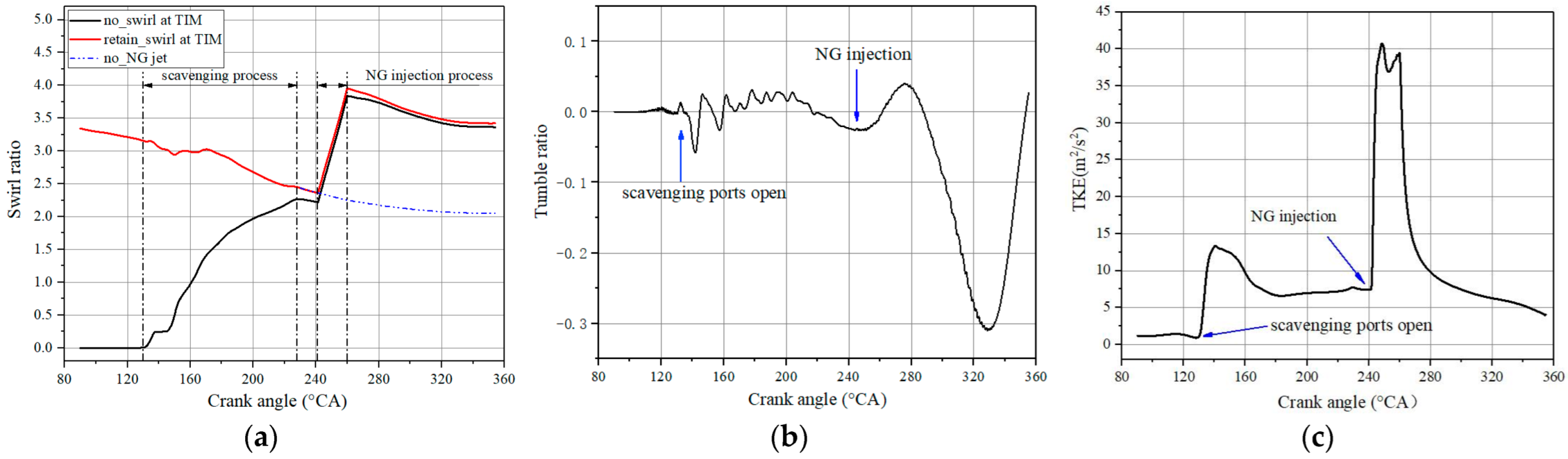
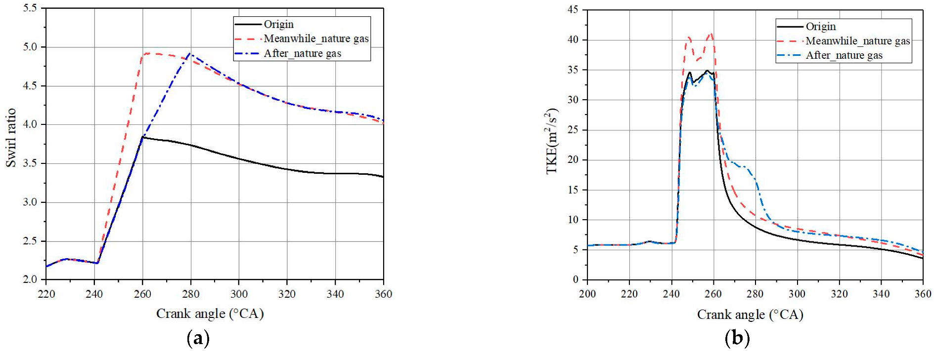
Figure 8 displays the variation of swirl ratio (SR) and tumble ratio (TR) and turbulent kinetic energy (TKE) with crankshaft angles during the scavenging process and compression process from 90 °CA to 350 °CA. It can be observed that the formation and change from the in-cylinder flow field are mainly affected before the diesel injection by the scavenging process and NG injection process. Figure 8a shows the result of comparing the calculated SR under two different initial flow fields, in the cylinder and without the NG injection process. On one hand, it shows that for the calculated result of no flow field in the cylinder at the initial moment (black line), the SR begins to rise rapidly after the scavenging port is opened. However, when the flow field after combustion is adopted as the in-cylinder initial condition (red line), the SR basically shows a downward trend during the scavenging process. The main reason is that the angular momentum of the overall gas in the cylinder decays faster than the swirl provided by the scavenging process. On the other hand, it can be observed that by comparing it with the SR calculated without NG injection process (blue dotted line), the injection of NG has great influence on the level of swirl in the cylinder. This is mainly due to the transverse flow movement in the cylinder being enhanced, resulting in NG being injected into the cylinder at a certain angle along the direction of the original flow field in the cylinder. 
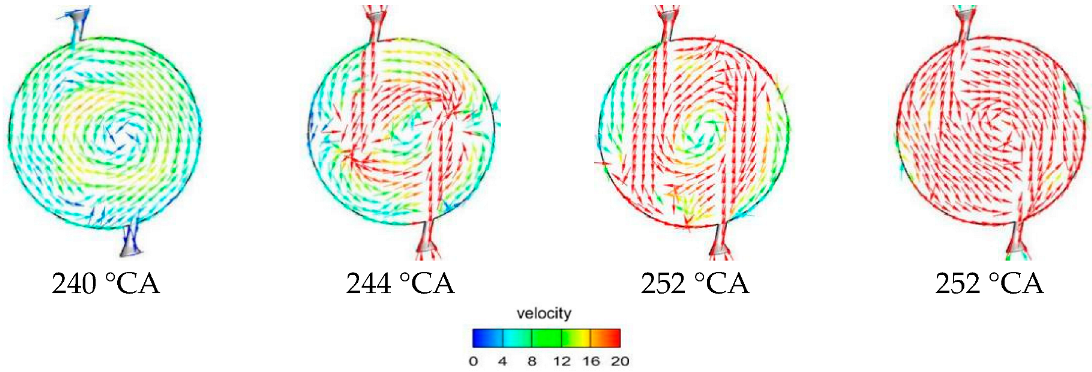
Figure 9 shows the variation of velocity distribution on a cross section of NG injection valves during the injection process of nature gas. It shows that the process of NG injection clearly impacts the flow field originally formed by the scavenging gas and promotes the swirl movement in the cylinder.
Figure 8b presents the evolution of TR in the cylinder. Compared to Figure 8a, it is observed that the change degree of the SR is obviously higher than that of the TR during the process of scavenging and NG injection. It indicates that the level of in-cylinder swirl has a great impact on the flow field in the cylinder. Figure 8c presents the variation of the TKE with crankshaft angles during the process of scavenging and compression. It illustrates that the influence of the NG injection process on the in-cylinder turbulence is obviously higher than that of the scavenging process. The main reason is that during the injection process of NG, the large speed of the injection makes the swirl continuously generate in the cylinder and form a strong turbulence.
The above numerical results indicate that the level of swirl directly effects the flow field and can be used as an evaluation index of airflow movement in the process of ventilation and compression. Moreover, the injection process of NG has a significant influence on the level of swirl, which will directly affect the mixing process and the formation quality and distribution of premixed gas.

3.2.2. Effects of NG Injection Condition on NG Distribution

In order to further analyze the effect of NG injection on the in-cylinder flow field and mixture distribution in the cylinder, by changing the NG injection valve structure and NG injection conditions to analyze the effects of NG injection pressure, NG injection angle and the number of gas valves on the swirl and the turbulence, the effect of NG injection conditions on NG distribution is obtained.
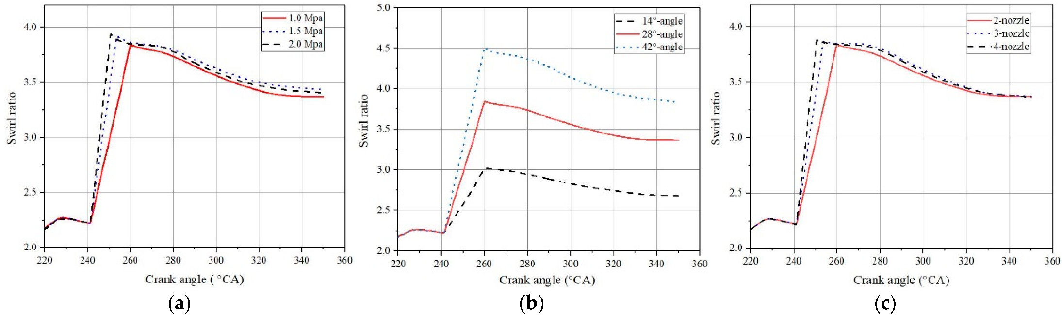
Figure 10 displays the variation of SR for different NG injection conditions. Figure 10a,c shows that with the increase in the number of NG nozzles and injection pressure, the SR increases slightly during the NG injection process. However, the SR is not significantly improved after the end of the natural gas injection, and the swirl movement level in the cylinder is basically the same as before fuel injection. It is explained that increasing the injection pressure and the number of injection nozzles leads to the speed of the injection outlet being improved and the promotion effect of the NG injection on the swirl in-cylinder being enhanced in the process of NG injection. In order to ensure the same gas injection quality, the injection duration is shortened when the injection pressure is enhanced and the number of injection nozzles is increased. Therefore, the change of pressure and number of injection valves have little influence on the promoting the swirl motion of the original flow field. Additionally, as displayed in Figure 10b, with the increase in injection angle, the strengthening effect of the NG injection on the SR becomes more obvious. This is mainly caused by the interference between the two NG flows becoming stronger with the decreasing injection angle, resulting in the strengthening effect of the NG injection on swirl being relatively reduced.
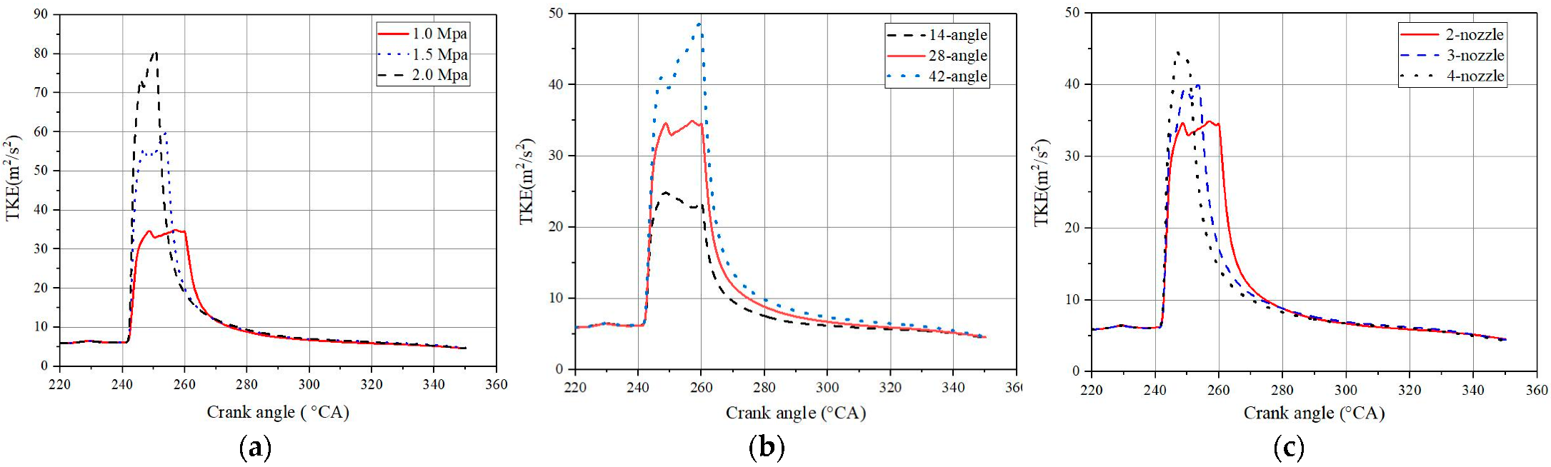
The comparison of average TKE for different injection conditions of NG is presented in Figure 11. As depicted in Figure 11, the turbulence intensity is enhanced during the NG injection process with the increasing injection pressure and number of injection nozzles. However, the TKE of each scheme gradually decreases after the end of the NG injection and tends to be consistent at near TDC, which indicates that the conditions of NG injections have little influence on the in-cylinder TKE due to the injection mass remaining unchanged for different injection conditions; this means that there is no extra energy to compensate for the dissipation of TKE, leading to the interference intensity of the NG injection process on the original flow field in the cylinder not changing significantly.
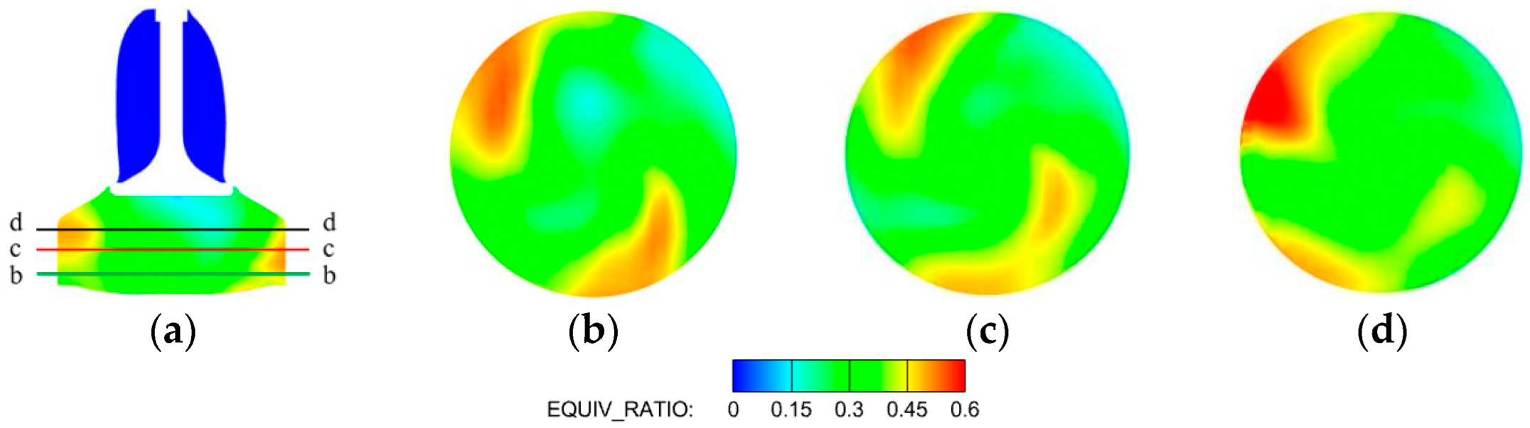
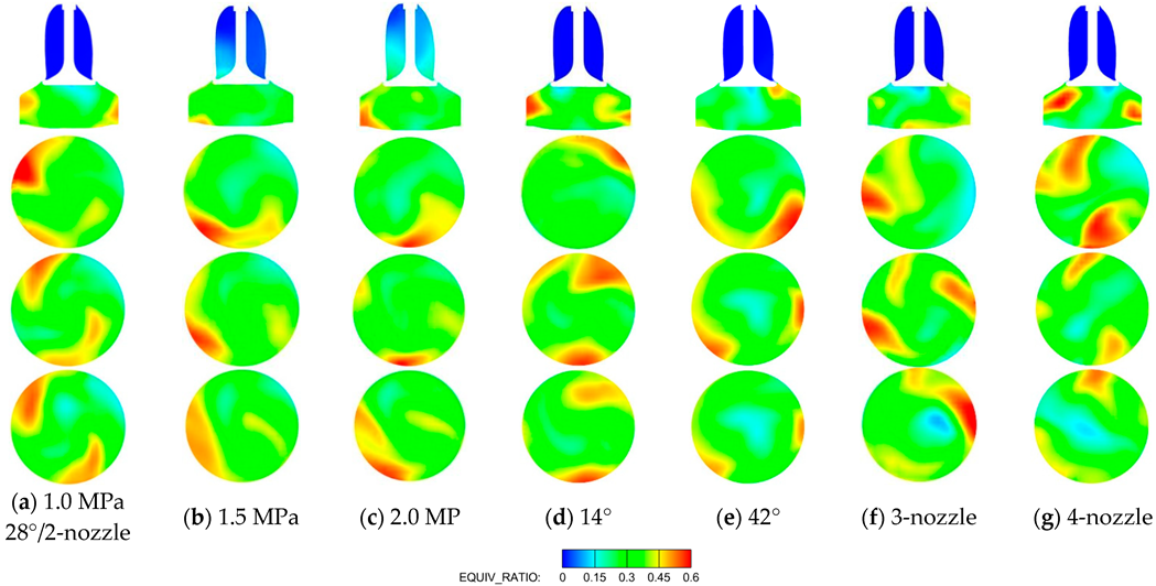
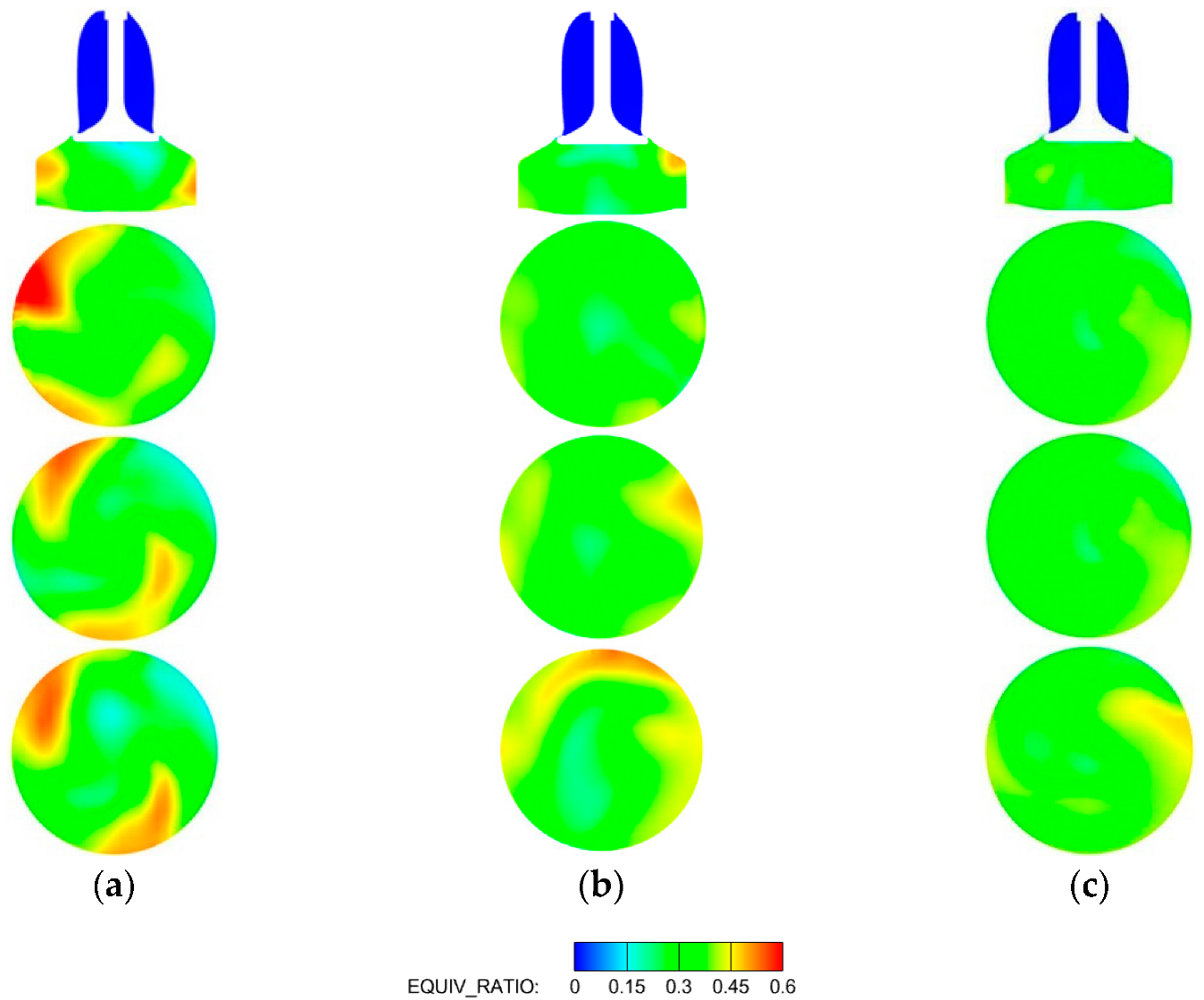
Figure 12 illustrates the distribution of CH4 for different NG injection conditions at −10° ATDC. The position of sections in Figure 12 is consistent with Figure 6. Figure 12a shows the distribution of in-cylinder equivalence ratios calculated under the condition of original gas injection. Compared with the case of Figure 12a, changing the NG injection conditions has no obvious improvement in the quality of the mixture. On the contrary, Figure 12b,c show that the mass of CH4 escaping from the exhaust valve increases with the increasing injection pressure. Moreover, Figure 12d–g show that the areas of high and low concentration of CH4 expand with increasing injection angle and the number of injection nozzles. The reason is mainly that although the different conditions of NG injection could cause different degrees of disturbance to the in-cylinder flow field during the NG injection process, the overall average TKE in the cylinder has not been significantly improved after the end of the NG injection. Thus, changing the injection conditions does not significantly enhance the mixing process.
As mentioned above, it can be concluded that the increase in swirl intensity during the process of natural gas injection has little influence on the distribution of the equivalence ratio before TDC. To further reveal the effect of swirl on the flow field and the distribution of equivalence ratio in cylinder, the influence of the swirl motion in the formation and distribution of the in-cylinder mixture was studied in by removing the component of the swirl motion. In the simulation calculation process, the X/Y movement speed of the in-cylinder gas at the end of the NG injection (260 °CA) was removed by applying the MAP function of CONVERGE, which realized the calculation of no swirl motion in the cylinder at the initial moment.
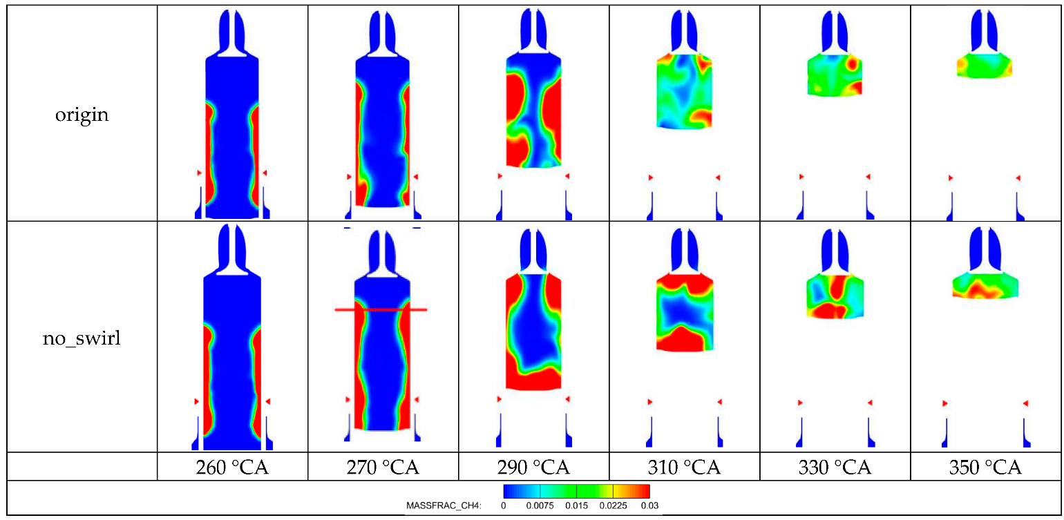
Figure 13 displays the CH4 distribution of the Y-direction in the cylinder at the conditions of swirl motion and no swirl motion. The result shows that the distribution of CH4 is basically the same from the end of the NG injection (260 °CA) to the exhaust valve being closed (290 °CA), and is distributed near the cylinder wall and mainly moves upward along the wall surface. However, when the exhaust valve is closed (290 °CA), there is an obvious difference between the distribution of CH4 under the condition of no swirl motion compared to that in the presence of swirl motion; the distribution of CH4 appears to be a stratified phenomenon in the compression process. The reason is that the velocity of gas radial diffusion is lower, due to the cylinder swirl movement being removed from the cylinder at the initial moment.
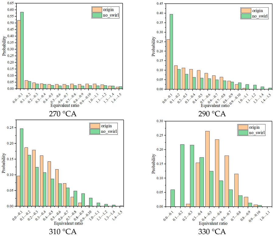
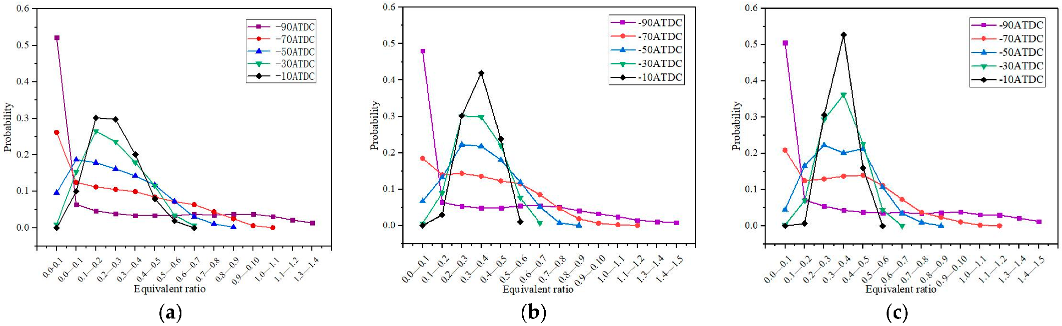
Figure 14 shows the density probability distribution of equivalence ratios under different swirl states after NG injection. The density probability distribution of equivalence ratios under the condition of no swirl motion at the initial time is not obviously different compared with that of the condition of swirl motion in the cylinder during a period of time after the NG injection (270 °CA–290 °CA). When the exhaust valve is closed (290 °CA), the overall equivalence ratio distribution in the cylinder is obviously different, with the piston running upward. This implies that the influence of the swirl movement of the late compression process on the transportation of NG is higher than that before the exhaust valve is closed. Meanwhile, the distribution of CH
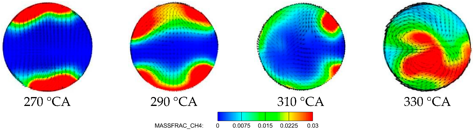
4 and the velocity vector of the Z-direction section in-cylinder under the condition of no swirl at the initial moment are depicted in Figure 15. The red horizontal line in Figure 13 is the selected slice location of Figure 15. As seen in Figure 15, at the late stage of the compression process, a swirl motion is formed in the cylinder as the piston moves upward, which promotes the radial diffusion of CH4 from the cylinder wall. Therefore, it further illustrates that the level of swirl of the late compression stage has an important influence on the uniformity of gas distribution.
From the above discussion, it can be deduced that the main factors affecting the transmission process of NG and distribution of CH4 concentration are the level of swirl at the late compression stage and the turbulence intensity in-cylinder. Therefore, it is essential to improve the level of swirl in the cylinder at an appropriate time and increase the turbulence intensity in the cylinder without affecting the gas injection quality and pressure, so as to compensate for the attenuation of turbulent motion.

3.3. Methods to Improve the Intensity of Swirl in Cylinder

In this part, a method is proposed to promote the level of in-cylinder swirl movement. By injecting a certain amount of air into the cylinder during and after the NG injection, the mixing of NG and air is strengthened to form a uniform mixture before the diesel injection. In order to add the air injection process to the simulation, two injection valve structures (red color valve in Figure 16) are symmetrically added on the cylinder, which are installed at the same height as the NG injection valves. Figure 16 shows the position and structure of the jet valve. This paper adopts two schemes of air injection during and after the NG injection for comparative analysis to study the impact of air injection on mixture quality in depth. The parameter settings of air injection are consistent with those of NG injection, and the specific simulation parameter settings are shown in Table 5.
Figure 17 compares the calculated change of in-cylinder SR and TKE with crankshaft angles for two different air injection times. As shown in Figure 17a, the intensity of the swirl movement is obviously improved due to the air injection process strengthening the energy of the transverse large-scale eddy in-cylinder, which accelerates the angular velocity of the transverse swirl. Moreover, Figure 17b shows that during the NG injection process, the disturbances of NG and air simultaneously are jetted into the cylinder, which is relatively higher compared to that of the condition of air injected late into the cylinder. However, under the condition of air injection after natural gas, the process of air injection can better compensate the dissipation of turbulence. Thus, the TKE in the compression process is improved compared to other two conditions.
Figure 18 displays the comparison of the density probability distribution of the equivalence ratio in the cylinder under different air injection times. Figure 18b,c show that the profiles turn narrower and taller under the condition of air injection compared to those of without air injection when the piston moves to TDC. Moreover, the probability of the average equivalence ratio 0.345 increases, and too-low and too-high equivalence ratios gradually disappear, which suggests that the mixing uniformity in the cylinder is improved due to the increase in the velocity of air flow by the injection of air.
The distribution of equivalence ratios before the flame jet (−10 ATDC) are shown in Figure 19. The position of sections is consistent with Figure 6. Figure 19b,c show that the distribution of equivalence ratios in the cylinder before TDC has improved, where the uneven areas of local equivalence ratio obviously decrease compared to those without air injection. This illustrates that the in-cylinder fuel/air mixing quality is improved. Moreover, the result shows that the area of high concentration of mixtures calculated by injecting air into the cylinder after the NG injection is smaller than that calculated by injecting air and NG at the same time. On one hand, when air and NG are sprayed at the same time, the collision of natural gas and air affects NG diffusion in-cylinder. On the other hand, this also explains that promoting the level of swirl of the late compression stage has an important influence on the uniformity of NG distribution.
Figure 20 displays that at the condition where the air injection time is 260 °CA, the distribution of in-cylinder 1200 K temperature iso-surfaces indicate the flame propagation process in the combustion chamber. The position of the Z-direction slice is consistent with that in Figure 6a d-d. As shown in Figure 20, there is no abnormal combustion occurring in the combustion chamber compared to that without air injection, which is displayed in Figure 7. The result indicates that the level of swirl is enhanced by injecting air, which could advance the mixing uniformity and avoid the occurrence of abnormal combustion in the cylinder. Thus, it further illustrates that the formation quality and distribution of premixed gas is an essential precondition to ensure efficient combustion under lean conditions while avoiding abnormal combustion phenomena. In addition, compressed air needs to be installed for the engine start, exhaust valve air springs and general services for the large-bore marine engine, whose pressure is usually between 25 and 30 bar. Therefore, it is possible to adopt the original air compressor and the required piping and valves and control system to establish the air injection system in order to achieve air injection into the cylinder. The design method developed in this study has promising potential for low-speed lean-burn dual-fuel marine engines.

4. Conclusions

In this study, a series of simulations were conducted to reveal the natural gas/air mixing mechanism of a super-large-bore dual-fuel marine engine, and a method was proposed to advance the mixing uniformity and avoid the occurrence of abnormal combustion. The main conclusions are summarized below:
(1)
The calculated results reveal the disadvantage of even mixture formation due to the characteristics of low flow-field disturbance and rapid dissipation of TKE of large-bore marine engines, which leads to the phenomenon of abnormal combustion occurring at the area of accumulation of NG in the cylinder.
(2)
The numerical simulation results show that the level of swirl has a greater influence on the flow field in-cylinder and NG transportation compared to the tumble during the scavenging and compression process. In addition, the NG injection process plays a more important role in the swirl and turbulence in the cylinder compared to the scavenging process.
(3)
Furthermore, the simulation results reveal that the main factors affecting the transmission process of NG and distribution of CH4 concentration are the intensity of in-cylinder turbulence and the level of swirl at the late compression stage. However, the enhanced swirl intensity by changing the condition of NG has little effect on the transmission process of NG and distribution of CH4 concentration.
(4)
With a certain amount of air injected into the cylinder, the area of high concentration of mixtures before TDC decreases significantly. It illustrates that the strategy can effectively improve the premixed charge mixing and avoids the occurrence of abnormal combustion in the cylinder. Moreover, this solution can be implemented by applying the original air compression system of marine engines, which will expand the application of NG in marine engines.

Author Contributions

Conceptualization, L.L. and S.L.; funding acquisition, L.L.; investigation, S.L.; methodology, S.L.; software, S.L.; writing—original draft preparation, S.L.; writing—review and editing, L.L. and X.M.; supervision, L.L. and X.M.; resources, Q.X. and B.L. All authors have read and agreed to the published version of the manuscript.

Funding

This research was funded by Key Program of National Natural Science Foundation of China (Grant No. 52130605), Natural Science Foundation for Distinguished Young Scholars of Heilongjiang Province (Grant No. JQ2020E005), and Key Program of Tianjin University State Key Laboratory of Engines Open Topics (Grant No. K2022-03).

Conflicts of Interest

The authors declare no conflict of interest.

Abbreviations

3-DThree-Dimensional
ATDCAfter Top Dead Centre
CFDComputational Fluid Dynamics
CH4Methane
DFDual-Fuel
DCCDynamic Combustion Control
EVCExhaust Valve Closing
HFOHeavy Fuel Oil
IMOInternational Maritime Organization
MDO Marine Diesel Oil
NGNatural Gas
NOxNitrogen Oxides
PDFProbability Density Function
SRSwirl Ratio
TDCTop Dead Center
TRTumble Ratio
TKETurbulence Kinetic Energy
Win GDWinterthur Gas and Diesel

References

  1. Larsen, U.; Wronski, J.; Andreasen, J.G.; Baldi, F.; Pierobon, L. Expansion of organic Rankine cycle working fluid in a cylinder of a low-speed two-stroke ship engine. Energy 2017, 119, 1212–1220. [Google Scholar] [CrossRef]
  2. Zhu, Y.; Zhou, W.; Xia, C.; Hou, Q. Application and Development of Selective Catalytic Reduction Technology for Marine Low-Speed Diesel Engine: Trade-Off among High Sulfur Fuel, High Thermal Efficiency, and Low Pollution Emission. Atmosphere 2022, 13, 731. [Google Scholar] [CrossRef]
  3. Yoo, B.-Y. Economic assessment of liquefied natural gas (LNG) as a marine fuel for CO2 carriers compared to marine gas oil (MGO). Energy 2017, 121, 772–780. [Google Scholar] [CrossRef]
  4. International Maritime Organization (IMO). Greenhouse Gas Emissions; International Maritime Organization: London, UK, 2018. [Google Scholar]
  5. Degiuli, N.; Martić, I.; Farkas, A.; Gospić, I. The impact of slow steaming on reducing CO2 emissions in the Mediterranean Sea. Energy Reports 2021, 7, 8131–8141. [Google Scholar] [CrossRef]
  6. Ampah, J.D.; Yusuf, A.A.; Afrane, S.; Jin, C.; Liu, H. Reviewing two decades of cleaner alternative marine fuels: Towards IMO’s decarbonization of the maritime transport sector. J. Clean. Prod. 2021, 320, 128871. [Google Scholar] [CrossRef]
  7. Elkafas, A.G.; Elgohary, M.M.; Shouman, M.R. Numerical analysis of economic and environmental benefits of marine fuel conversion from diesel oil to natural gas for container ships. Environ. Sci. Pollut. Res. Int. 2021, 28, 15210–15222. [Google Scholar] [CrossRef]
  8. Iannaccone, T.; Landucci, G.; Tugnoli, A.; Salzano, E.; Cozzani, V. Sustainability of cruise ship fuel systems: Comparison among LNG and diesel technologies. J. Clean. Prod. 2020, 260, 121069. [Google Scholar] [CrossRef]
  9. Wei, L.; Geng, P. A review on natural gas/diesel dual fuel combustion, emissions and performance. Fuel Process. Technol. 2016, 142, 264–278. [Google Scholar] [CrossRef]
  10. Richardson, D.E. Review of Power Cylinder Friction for Diesel Engines. J. Eng. Gas Turbines Power 2000, 122, 506–519. [Google Scholar] [CrossRef]
  11. Chen, Y.; Raine, R. A study on the influence of burning rate on engine knock from empirical data and simulation. Combust. Flame 2015, 162, 2108–2118. [Google Scholar] [CrossRef]
  12. Feng, D.; Buresheid, K.; Zhao, H.; Wei, H.; Chen, C. Investigation of lubricant induced pre-ignition and knocking combustion in an optical spark ignition engine. Proc. Combust. Inst. 2019, 37, 4901–4910. [Google Scholar] [CrossRef]
  13. Chen, L.; Zhang, R.; Wei, H.; Pan, J. Effect of flame speed on knocking characteristics for SI engine under critical knocking conditions. Fuel 2020, 282. [Google Scholar] [CrossRef]
  14. Liu, L.; Wu, Y.; Wang, Y. Numerical investigation on knock characteristics and mechanism of large-bore natural gas dual-fuel marine engine. Fuel 2022, 310, 118846. [Google Scholar] [CrossRef]
  15. Gürbüz, H.; Akçay, İ.H.; Buran, D. An investigation on effect of in-cylinder swirl flow on performance, combustion and cyclic variations in hydrogen fuelled spark ignition engine. J. Energy Inst. 2014, 87, 1–10. [Google Scholar] [CrossRef]
  16. Cao, Z.; Wang, T.; Sun, K.; Cui, L.; Gui, Y. Numerical Analysis of Scavenging Process in a Large Marine Two-Stroke Diesel Engine; SAE Technical Paper Series; Society of Automotive Engineers (SAE): Warrendale, PA, USA, 2017. [Google Scholar]
  17. Yousefi, A.; Guo, H.; Birouk, M. Effect of swirl ratio on NG/diesel dual-fuel combustion at low to high engine load conditions. Appl. Energy 2018, 229, 375–388. [Google Scholar] [CrossRef]
  18. Wang, G.; Yu, W.; Li, X.; Su, Y.; Yang, R.; Wu, W. Experimental and numerical study on the influence of intake swirl on fuel spray and in-cylinder combustion characteristics on large bore diesel engine. Fuel 2019, 237, 209–221. [Google Scholar] [CrossRef]
  19. Choi, M.; Park, S. Effects of intake air conditions and micro-pilot (MP) injection timing on micro-pilot dual fuel (MPDF) combustion characteristics in a single cylinder optical engine. Energy Convers. Manag. 2022, 254, 115281. [Google Scholar] [CrossRef]
  20. Liu, Z.; Zhou, L.; Liu, B.; Zhao, W.; Wei, H. Effects of equivalence ratio and pilot fuel mass on ignition/extinction and pressure oscillation in a methane/diesel engine with pre-chamber. Appl. Therm. Eng. 2019, 158, 113777. [Google Scholar] [CrossRef]
  21. Yousefi, A.; Guo, H.; Birouk, M. Split diesel injection effect on knocking of natural gas/diesel dual-fuel engine at high load conditions. Appl. Energy 2020, 279, 115828. [Google Scholar] [CrossRef]
  22. Yang, B.; Ning, L.; Liu, B.; Huang, G.; Cui, Y.; Zeng, K. Comparison study the particulate matter characteristics in a diesel/natural gas dual-fuel engine under different natural gas-air mixing operation conditions. Fuel 2021, 288, 119721. [Google Scholar] [CrossRef]
  23. Abdelaal, M.M.; Rabee, B.A.; Hegab, A.H. Effect of adding oxygen to the intake air on a dual-fuel engine performance, emissions, and knock tendency. Energy 2013, 61, 612–620. [Google Scholar] [CrossRef]
  24. Liu, L.; Wu, Y.; Xiong, Q.; Liu, T. Analysis on flow motion and combustion process in pre-chamber and main chamber for low-speed two-stroke dual. SAE Technol. Pap. 2019. [Google Scholar] [CrossRef]
  25. Li, M.; Zhang, Q.; Li, G.; Li, P. Effects of hydrogen addition on the performance of a pilotignition direct-injection natural gas engine: A numerical study. Energy Fuel 2017, 31, 4407–4423. [Google Scholar] [CrossRef]
  26. Mavrelos, C.; Theotokatos, G. Numerical investigation of a premixed combustion large marine two-stroke dual fuel engine for optimising engine settings via parametric runs. Energy Convers. Manag. 2018, 160, 48–59. [Google Scholar] [CrossRef]
  27. Jiang, X.; Wei, H.; Zhou, L.; Chen, R. Numerical Study on the Effects of Multiple Injection Coupled with EGR on Combustion and NOx Emissions in a Marine Diesel Engine. Energy Procedia 2019, 158, 4429–4434. [Google Scholar] [CrossRef]
  28. Patterson, M.A.; Reitz, R.D. Modeling the effects of fuel spray characteristics on diesel engine combustion and emission. SAE Trans. 1998, 107, 27–43. [Google Scholar]
  29. Rahimi, A.; Fatehifar, E.; Saray, R.K. Development of an optimized chemical kinetic mechanism for homogeneous charge compression ignition combustion of a fuel blend of n-heptane and natural gas using a genetic algorithm. Proc. Inst. Mech. Eng. Part D J. Automob. Eng. 2010, 224, 1141–1159. [Google Scholar] [CrossRef]
  30. Özgül, E.; Şimşek, M.; Bedir, H. Use of thermodynamical models with predictive combustion and emission capability in virtual calibration of heavy duty engines. Fuel 2020, 264, 116744. [Google Scholar] [CrossRef]
  31. Naber, J.; Siebers, D. Effects of gas density and vaporization on penetration and dispersion of diesel sprays. SAE Technol. Pap. 1996, 105, 82–111. [Google Scholar]
  32. Von Rotz, B.; Herrmann, K.; Boulouchos, K. Experimental Investigation on the Characteristics of Sprays Representative for Large 2-Stroke Marine Diesel Engine Combustion System. SAE Technol. Pap. 2015. [Google Scholar] [CrossRef]
  33. Abidin, Z.; Florea, R.; Callahan, T. Dual Fuel Combustion Study Using 3D CFD Tool. SAE Technol. Pap. 2016. [Google Scholar] [CrossRef]
  34. Liu, H.; Li, J.; Wang, J.; Wu, C.; Liu, B.; Dong, J.; Liu, T.; Ye, Y.; Wang, H.; Yao, M. Effects of injection strategies on low-speed marine engines using the dual fuel of high-pressure direct-injection natural gas and diesel. Energy Sci. Eng. 2019, 7, 1994–2010. [Google Scholar] [CrossRef] [Green Version]
  35. Wang, H.; Gan, H.; Theotokatos, G. Parametric investigation of pre-injection on the combustion, knocking and emissions behaviour of a large marine four-stroke dual-fuel engine. Fuel 2020, 281, 118744. [Google Scholar] [CrossRef]
Figure 1. The geometric model of engine.
Atmosphere 13 01528 g001
Figure 2. The mesh refinement regions in the model.
Atmosphere 13 01528 g002
Figure 3. Comparison of cylinder pressure for different base grid size.
Atmosphere 13 01528 g003
Figure 4. Comparison of simulation and experiment spray penetration. (a) Spray penetration under non-evaporating condition. (b) Spray penetration under evaporating condition.
Atmosphere 13 01528 g004
Figure 5. Comparisons between the calculated and experimental cylinder pressure and HRR. The arrow represents the corresponding ordinate of the curve, which is a representation for cylinder pressure and HRR.
Atmosphere 13 01528 g005
Figure 6. Equivalence ratio distribution in narrow-equivalence ratio range in cylinder at −10ATDC. (ad) is four different positions of sections, which can show that equivalence ratio distribution in the cylinder and has been explanted in the manuscript. And (a) is longitudinal section of model, which is a common slice location.
Atmosphere 13 01528 g006
Figure 7. 1200 K temperature iso-surfaces in combustion chamber.
Atmosphere 13 01528 g007
Figure 8. The variation of flow field during the scavenging process and compression process. (a) The evolution of SR with crank angle. (b) The evolution of TR with crank angle. (c) The evolution of mean TKE with crank angle.
Atmosphere 13 01528 g008
Figure 9. Velocity distribution on cross section of natural gas injection valve.
Atmosphere 13 01528 g009
Figure 10. The calculated SR for different NG injection conditions. (a) Different injection pressure. (b) Different injection angle. (c) Different number of nozzles.
Atmosphere 13 01528 g010
Figure 11. The calculated mean TKE for different NG injection conditions. (a) Different injection pressure. (b) Different injection angle. (c) Different number of nozzles.
Atmosphere 13 01528 g011
Figure 12. Distribution of in-cylinder CH4 for different NG injection conditions at −10° ATDC.
Atmosphere 13 01528 g012
Figure 13. The distribution of CH4 concentrations under conditions of swirl and no swirl at the initial moment.
Atmosphere 13 01528 g013
Figure 14. The density probability distribution of equivalence ratios under different swirl states.
Atmosphere 13 01528 g014
Figure 15. Distribution of CH4 concentrations and velocity vectors of Z-direction under the condition of no swirl motion in-cylinder.
Atmosphere 13 01528 g015
Figure 16. The position and structure of the jet valve.
Atmosphere 13 01528 g016
Figure 17. Comparison of the calculated change of in-cylinder SR and TKE with crankshaft angles for two different air injection times. (a) In-cylinder mean SR curves. (b) In-cylinder mean TKE curves.
Atmosphere 13 01528 g017
Figure 18. The density probability distribution of equivalence ratios at different air injection conditions. (a) Original model without air injection. (b) Air and NG injection at the same time. (c) Air injection after the end of NG injection.
Atmosphere 13 01528 g018
Figure 19. Equivalence ratio distribution in narrow-equivalence ratio range for different air injection conditions at −10 ATDC. (a) Origin model without air injection. (b) Air and NG injection at the same time. (c) Air injection after the end of NG injection.
Atmosphere 13 01528 g019
Figure 20. A temperature isosurface of 1200 K in the case of air injection after the end of NG injection.
Atmosphere 13 01528 g020
Table 1. Parameters of Win GD X92DF engine.
ParametersValue
Cylinder number12
Bore/stroke [mm]920/3468
Engine speed [rpm]80
Compression ratio12.4
Engine output [KW]63,840
IMEP (MCR)17.3
Table 2. Parameter of 3D model.
ParametersValue
Engine load [%]100%
Initial cylinder pressure [bar]12.1
Initial temperature in cylinder [K]930
Scavenge inlet pressure [bar]4.7
Scavenge inlet temperature [K]301
Outlet pressure of exhaust [bar]4.55
Outlet pressure of exhaust temperature [K]737
Cylinder wall temperature [K]443
The SOI of the main diesel fuel [°CA/ATDC]−6
The SOI of the pilot diesel fuel [°CA/ATDC]−5
Table 3. Submodels applied for simulation.
ParametersModel
TurbulenceRNG κ-ε k-ε model
Gas injectionInflow boundary
Spray atomization and breakupKH-RT
Droplet collisionNTC collision method
Spray–wall interactionO’Rourke model
CombustionChemical kinetic model
NOxExtended Zeldovich model
Table 4. Determination of model grid strategy.
Grid StrategyRegionSize [mm]
Basic gridOverall model40
Scavenging port5
Natural gas injection5
Fixed embeddingCombustion region2.5
Precombustion chambers2.5
Diesel injection2.5
AMROverall model2.5
Table 5. Parameter of air injection.
ParametersValue
Nozzle diameter [mm]40
Injection duration [°CA]18
Injection angle [°]28
Injection pressure [MPa]1.4
Injection timing [°CA]During and after gas injection (242/260)
Publisher’s Note: MDPI stays neutral with regard to jurisdictional claims in published maps and institutional affiliations.

