
Real-Time Monitoring of Pellet Plastication in a Full-Flight Screw and Kneading Disk Elements of a Co-Rotating Self-Wiping Twin-Screw Extruder by Acoustic Emission (AE) Sensing


Abstract
:
1. Introduction
2. Materials and Methods
2.1. Materials
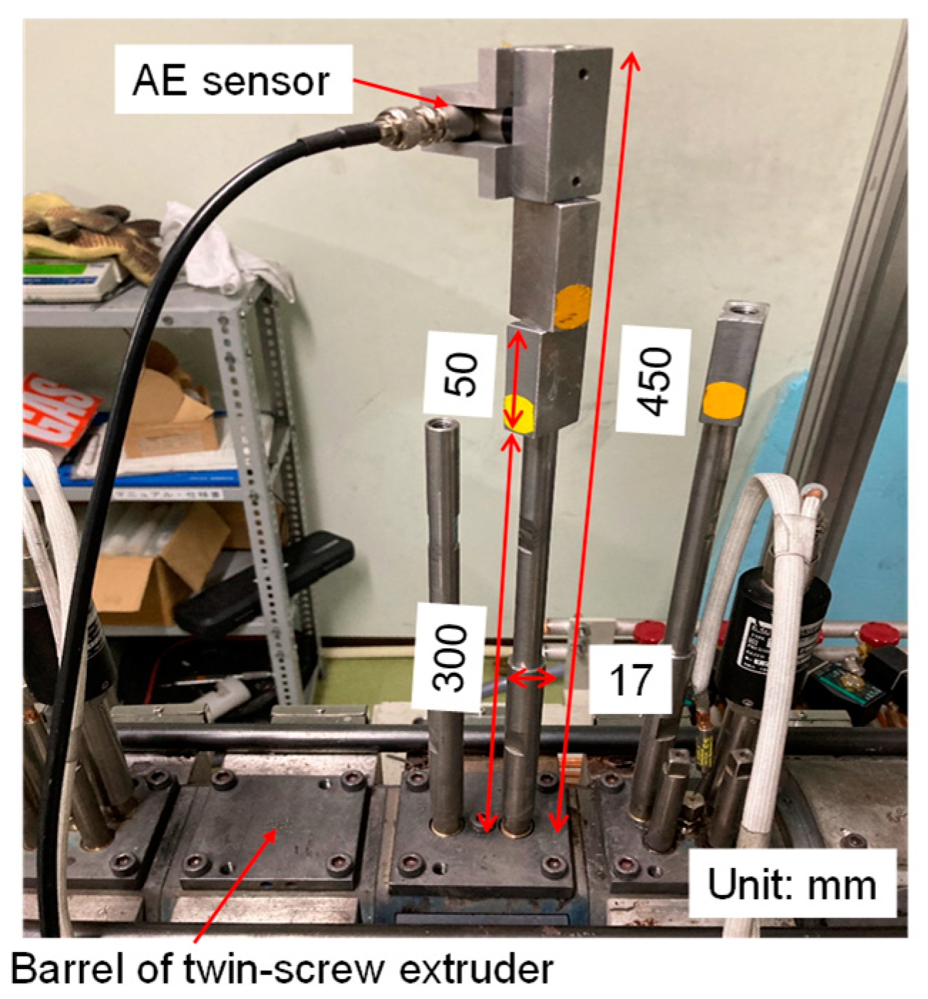
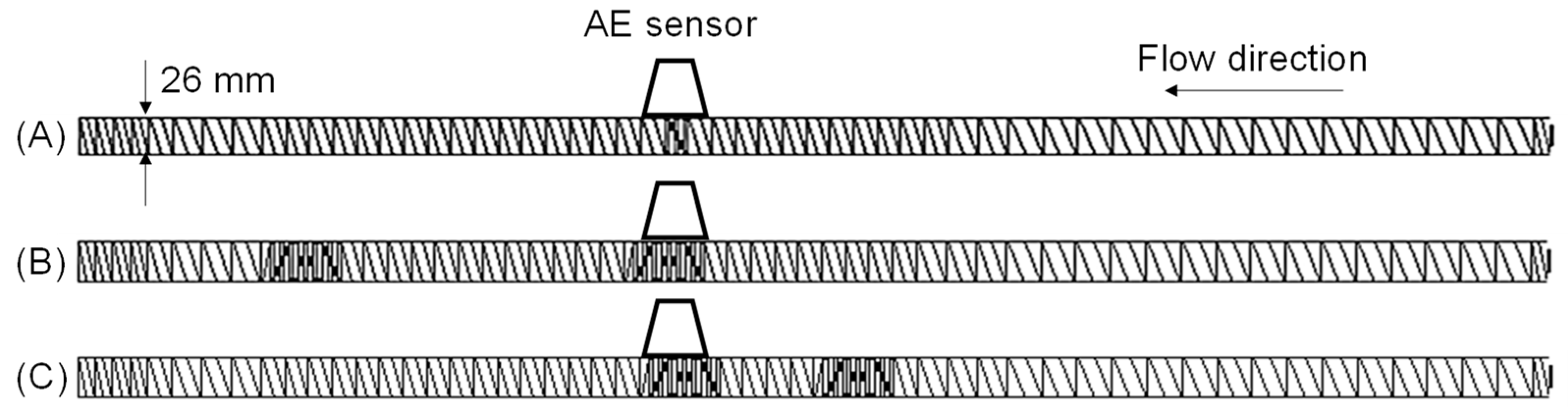
2.2. AE Sensor
2.3. Screw Configuration
2.4. Residence Time Measurement
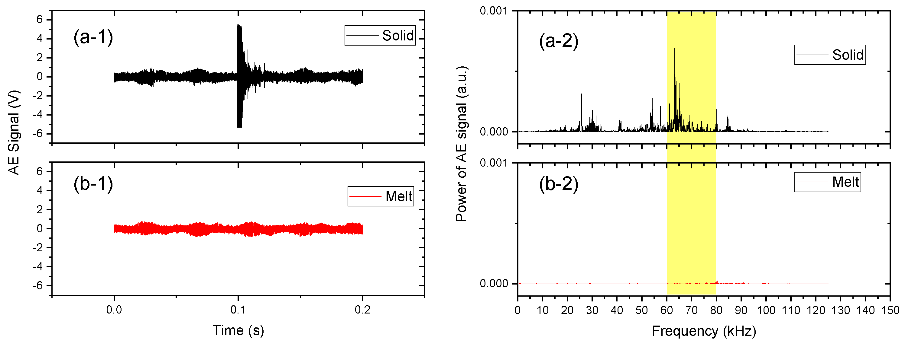
2.5. Signal Processing
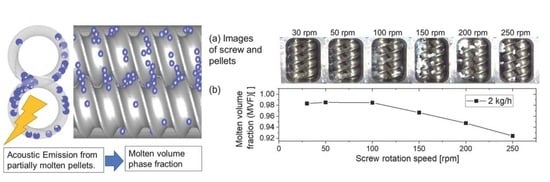
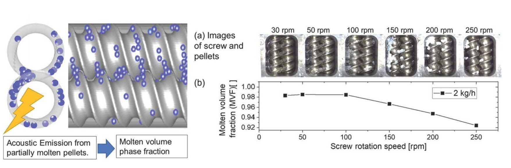
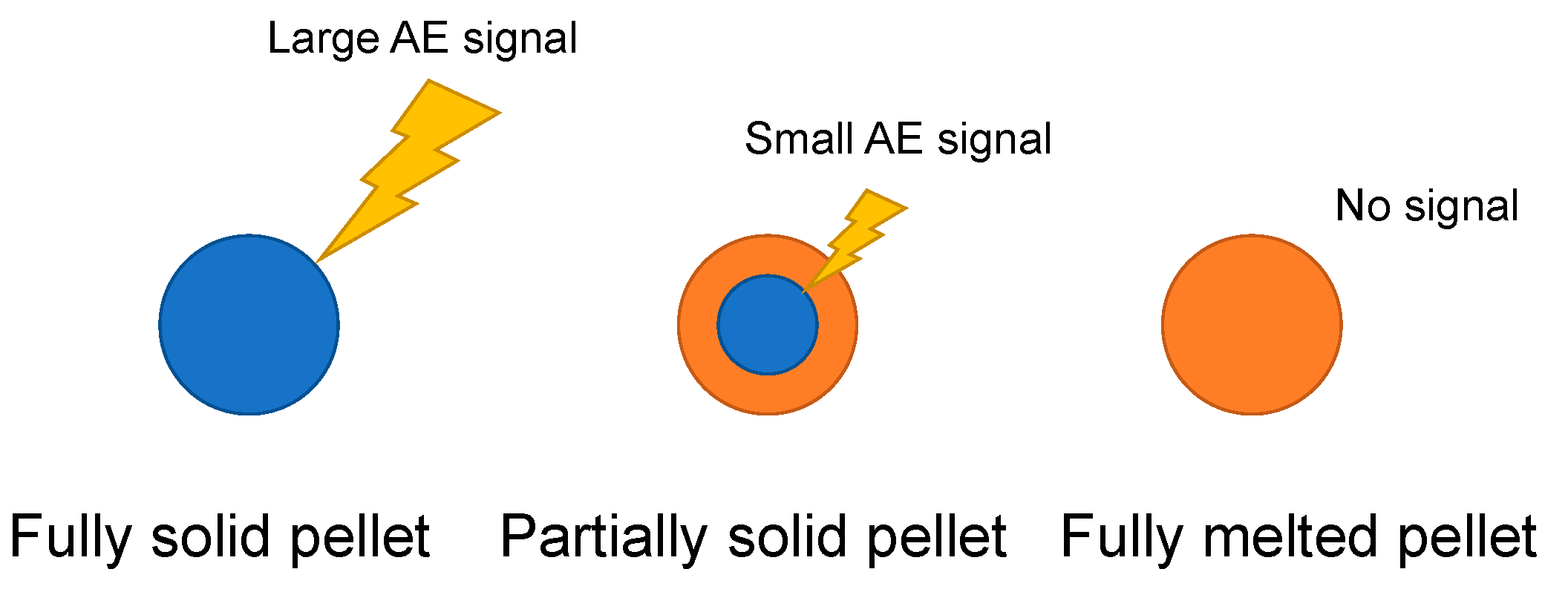
2.6. Molten Volume Fraction (MVF) from AE
3. Results and Discussion
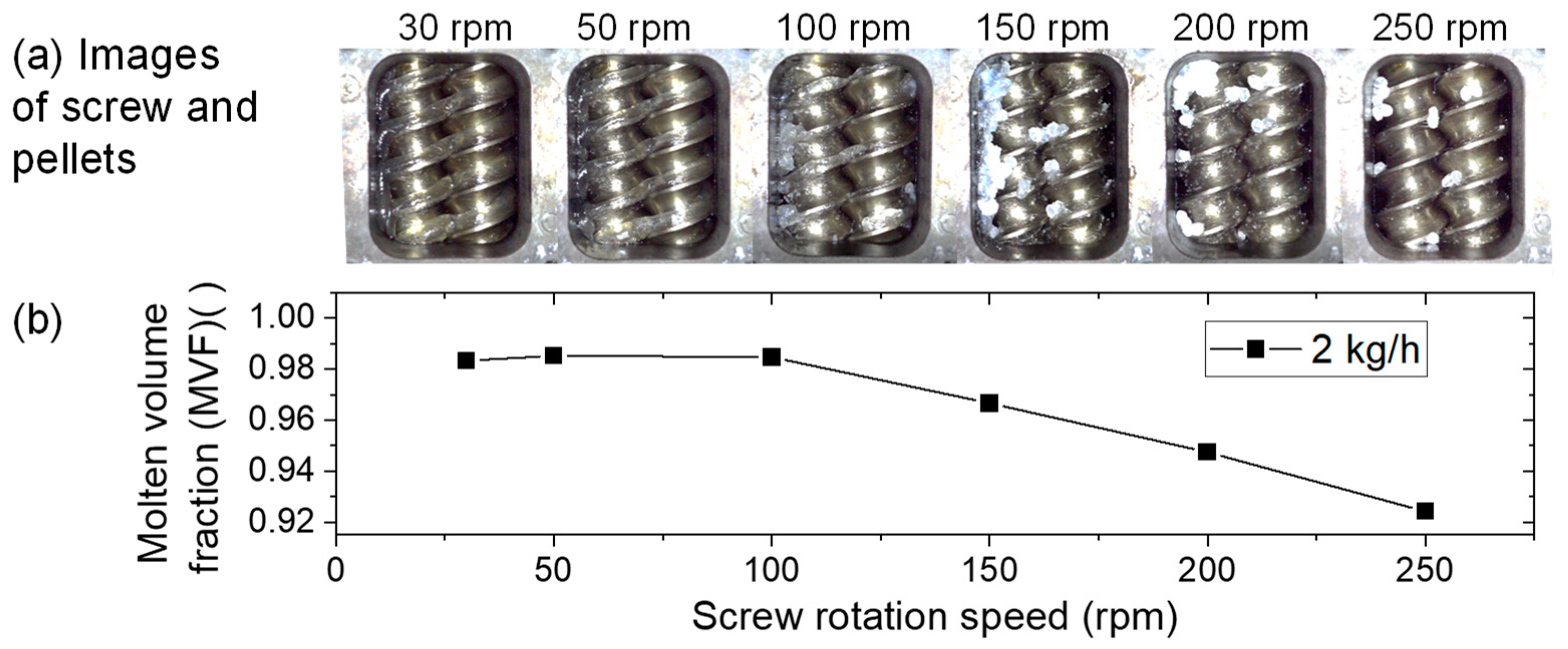
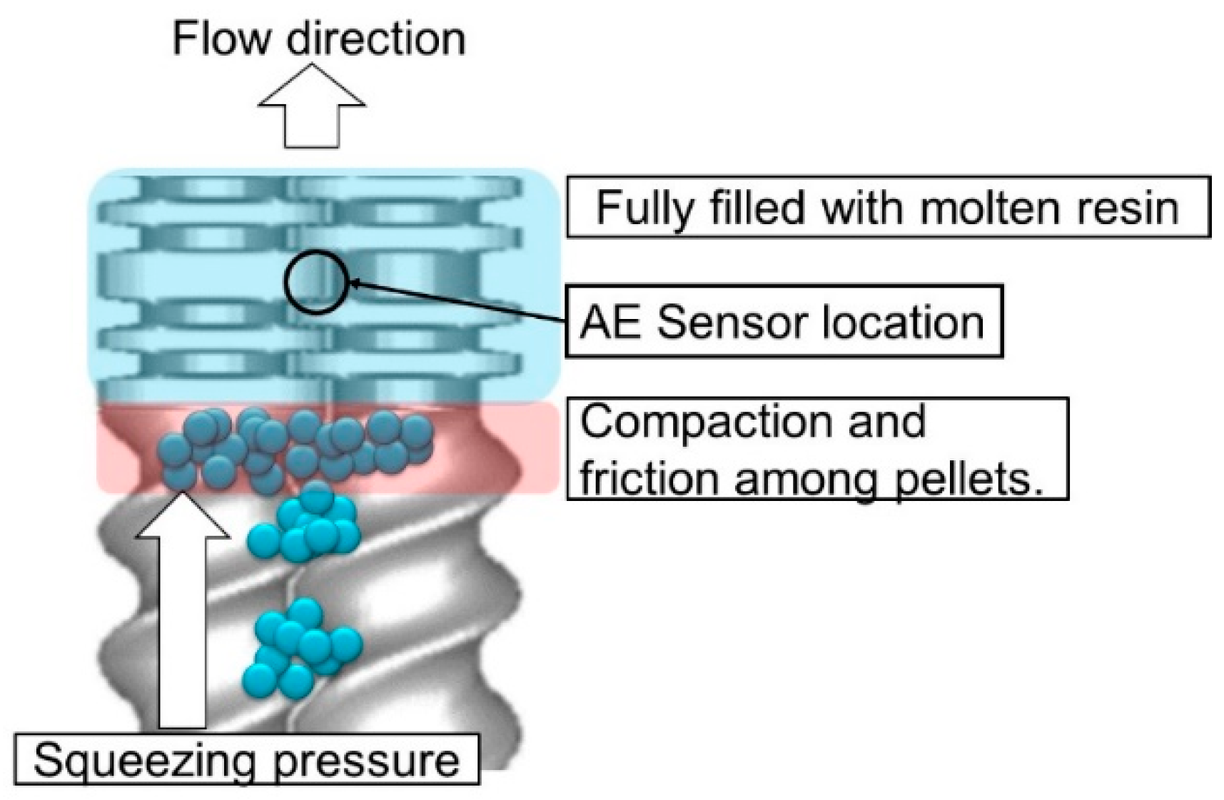
3.1. Visual Observation of Partially Molten State Pellets on Rotating Screws
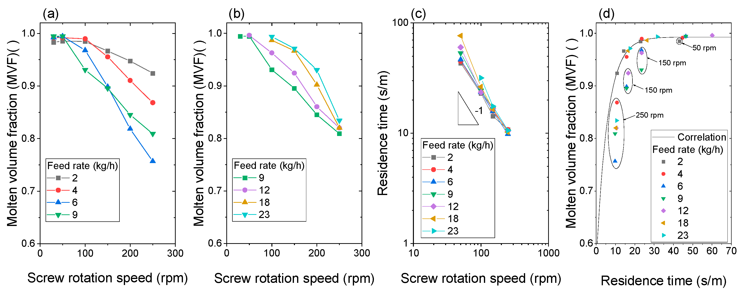
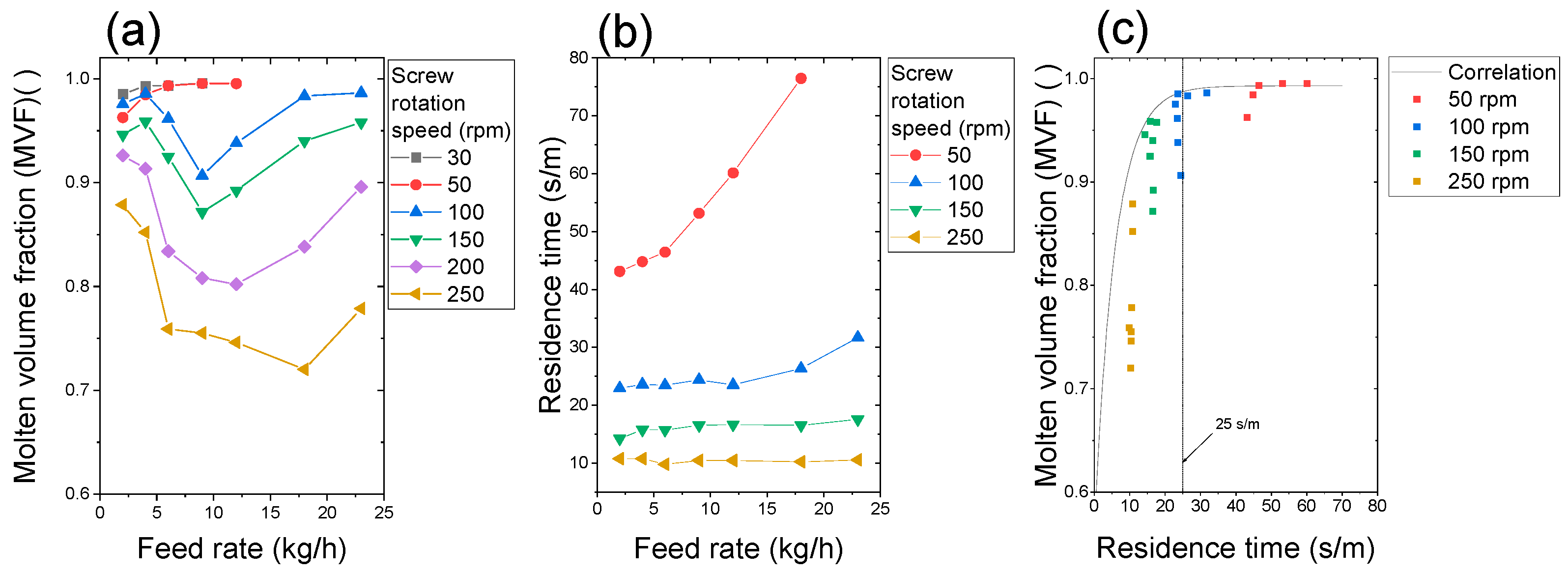
3.2. Effect of Increase in Screw Rotation Speed on Plastication at a Constant Feed Rate
3.3. Effect of Increase in Feed Rate on Plastication at Constant Screw Speed
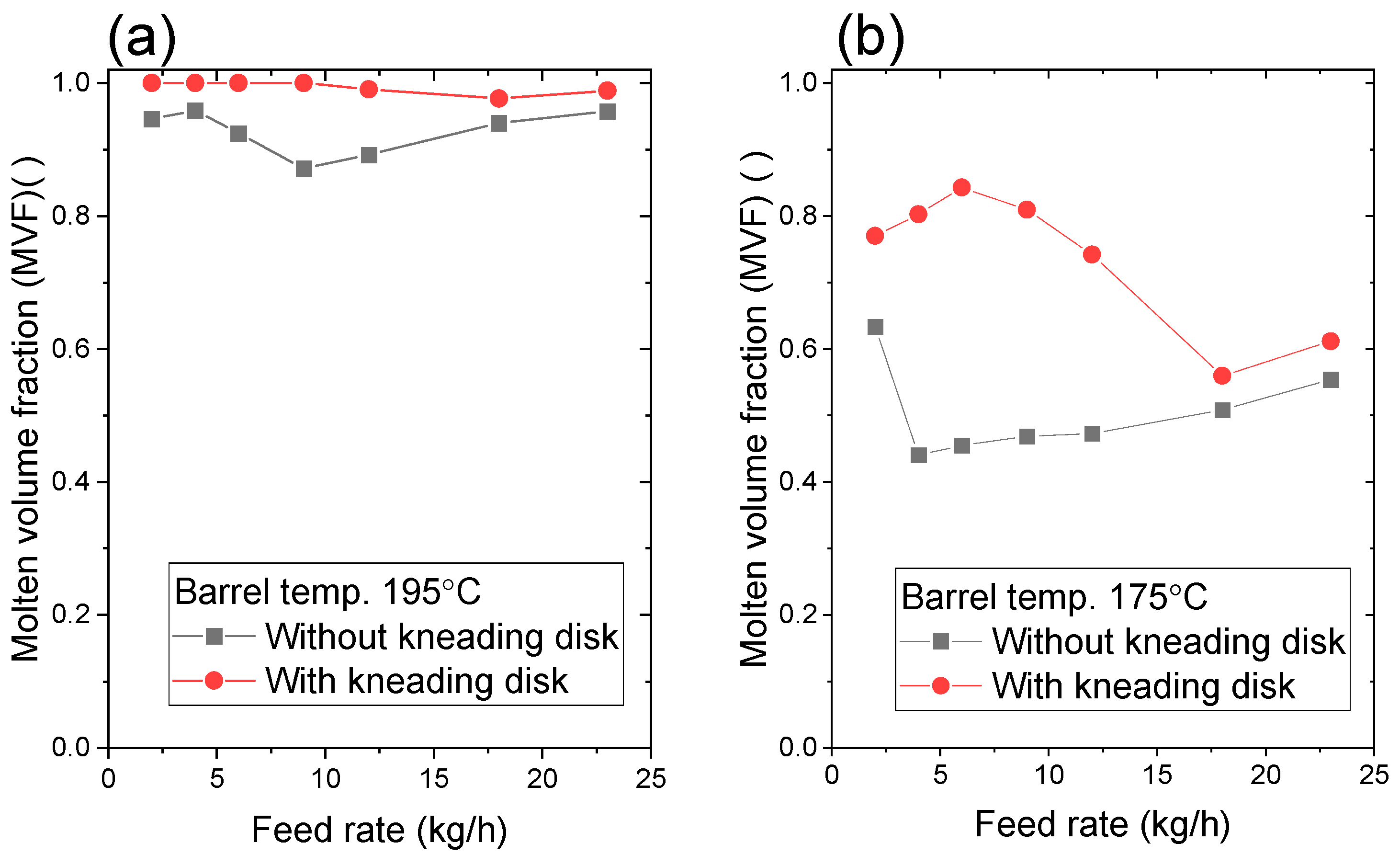
3.4. Effect of Kneading Disk
4. Conclusions
Supplementary Materials
Author Contributions
Funding
Institutional Review Board Statement
Data Availability Statement
Acknowledgments
Conflicts of Interest
Appendix A

| n (-) | B (Pa·s) | τ* (Pa) | Tb (°C) | |
|---|---|---|---|---|
| PP F-704NP | 0.4212 | 8.486 × 10⁻⁶ | 12,360 | 9472.1 |
| A | B | C | Residence Time Meas. | ||
|---|---|---|---|---|---|
| Feeder | - | - | - | - | |
| 1 | CL-3 | CL-3 | CL-3 | CL-3 | |
| 2 | SC-20/20 | SC-20/20 | SC-20/20 | SC-20/20 | |
| 3 | SC-40/40 | SC-40/40 | SC-40/40 | SC-40/40 | |
| 4 | SC-40/40 | SC-40/40 | SC-40/40 | SC-40/40 | |
| 5 | SC-40/40 | SC-40/40 | SC-40/40 | SC-40/40 | |
| 6 | SC-40/40 | SC-40/40 | SC-40/40 | SC-40/40 | |
| 7 | SC-40/40 | SC-40/40 | SC-40/40 | SC-40/40 | |
| 8 | SC-40/40 | SC-40/40 | SC-40/40 | SC-40/40 | |
| 9 | SC-40/40 | SC-40/40 | SC-40/40 | SC-40/40 | |
| 10 | SC-40/40 | SC-40/40 | SC-40/40 | SC-40/40 | |
| 11 | SC-40/40 | SC-40/40 | SC-40/40 | SC-40/40 | |
| 12 | SC-40/40 | SC-40/40 | SC-40/40 | SC-40/40 | |
| 13 | SC-40/40 | SC-40/40 | SC-40/40 | SC-40/40 | |
| 14 | SC-40/40 | SC-40/40 | SC-40/40 | SC-40/40 | |
| 15 | SC-40/40 | SC-40/40 | SC-40/40 | SC-40/40 | |
| 16 | SC-40/40 | SC-40/40 | SC-40/40 | SC-40/40 | |
| 17 | SC-40/40 | SC-40/40 | SC-40/40 | SC-40/40 | |
| 18 | SC-34/34 | SC-34/34 | SC-34/34 | SC-34/34 | |
| 19 | SC-34/34 | SC-34/34 | SC-34/34 | SC-34/34 | |
| 20 | SC-34/34 | SC-34/34 | SC-34/34 | SC-34/34 | |
| 21 | SC-27/27 | SC-27/27 | KD-27/5R | SC-27/27 | |
| 22 | SC-27/27 | SC-27/27 | KD-27/5N | SC-27/27 | |
| 23 | SC-27/27 | SC-27/27 | KD-27/5L | SC-27/27 | |
| 24 | SC-27/27 | SC-27/27 | SC-10/20L | SC-27/27 | |
| 25 | SC-27/27 | SC-27/27 | SC-27/27 | SC-27/27 | |
| 26 | SC-27/27 | SC-27/27 | SC-27/27 | SC-27/27 | |
| 27 | SC-27/27 | SC-27/27 | SC-27/27 | SC-27/27 | |
| 28 | SC-27/27 | SC-27/27 | SC-27/27 | SC-27/27 | |
| 29 | SC-27/27 | SC-27/27 | KD-27/5R | SC-27/27 | |
| 30 | KD-27/5R | KD-27/5R | KD-27/5N | Open head | |
| 31 | SC-27/27 | KD-27/5N | KD-27/5L | ←AE sensor here | - |
| 32 | SC-27/27 | KD-27/5L | SC-10/20L | - | |
| 33 | SC-27/27 | SC-10/20L | SC-27/27 | - | |
| 34 | SC-27/27 | SC-27/27 | SC-27/27 | - | |
| 35 | SC-27/27 | SC-27/27 | SC-27/27 | - | |
| 36 | SC-27/27 | SC-27/27 | SC-27/27 | - | |
| 37 | SC-27/27 | SC-27/27 | SC-27/27 | - | |
| 38 | SC-27/27 | SC-27/27 | SC-27/27 | - | |
| 39 | SC-27/27 | SC-27/27 | SC-27/27 | - | |
| 40 | SC-27/27 | SC-27/27 | SC-27/27 | - | |
| 41 | SC-27/27 | SC-27/27 | SC-27/27 | - | |
| 42 | SC-27/27 | SC-27/27 | SC-27/27 | - | |
| 43 | SC-27/27 | SC-27/27 | SC-27/27 | - | |
| 44 | SC-27/27 | SC-27/27 | SC-27/27 | - | |
| 45 | SC-27/27 | SC-27/27 | SC-27/27 | - | |
| 46 | SC-27/27 | KD-27/5R | SC-27/27 | - | |
| 47 | SC-27/27 | KD-27/5N | SC-27/27 | - | |
| 48 | SC-27/27 | KD-27/5L | SC-27/27 | - | |
| 49 | SC-27/27 | SC-10/20L | SC-27/27 | - | |
| 50 | SC-34/34 | SC-34/34 | SC-34/34 | - | |
| 51 | SC-34/34 | SC-34/34 | SC-34/34 | - | |
| 52 | SC-34/34 | SC-34/34 | SC-34/34 | - | |
| 53 | SC-27/27 | SC-27/27 | SC-27/27 | - | |
| 54 | SC-20/20 | SC-20/20 | SC-20/20 | - | |
| 55 | SC-20/20 | SC-20/20 | SC-20/20 | - | |
| 56 | SC-20/20 | SC-20/20 | SC-20/20 | - | |
| 57 | SC-20/20 | SC-20/20 | SC-20/20 | - | |
| Head | - | - | - | - |
References
- Tadmor, Z.T.; Gogos, C.G. Principles of Polymer Processing, 2nd ed.; Wiley-Interscience: Hoboken, NJ, USA, 2006; p. 984. [Google Scholar]
- Bawiskar, S.; White, J.L. Melting model for modular self wiping co-rotating twin screw extruders. Polym. Eng. Sci. 1998, 38, 727–740. [Google Scholar] [CrossRef]
- Potente, H.; Melisch, U. Theoretical and experimental investigations of the melting of pellets in co-rotating twin-screw extruders. Int. Polym. Process. 1996, 11, 101–108. [Google Scholar] [CrossRef]
- Vergnes, B.; Souveton, G.; Delacour, M.L.; Ainser, A. Experimental and theoretical study of polymer melting in a co-rotating twin screw extruder. Int. Polym. Process. 2001, 16, 351–362. [Google Scholar] [CrossRef]
- Kim, M.H. Melting Phenomena and Mechanisms in Polymer Processing Equipment. Ph.D. Thesis, Department of Chemical Engineering, Stevens Institutes of Technology, Hoboken, NJ, USA, 1999. [Google Scholar]
- Qian, B.; Gogos, C.G. The importance of plastic energy dissipation (PED) to the heating and melting of polymer particulates in intermeshing co-rotating twin-screw extruders. Adv. Polym. Technol. 2000, 19, 287–299. [Google Scholar] [CrossRef]
- Gogos, C.G.; Qian, B. Plastic energy dissipation during compressive deformation of individual polymer pellets and polymer particulate assemblies. Adv. Polym. Technol. 2002, 21, 287–298. [Google Scholar] [CrossRef]
- Zhu, L.; Narh, K.A. A simplified model for the melting of polymer pellets under compression in a twin-screw extruder. Simulation 2006, 82, 543–548. [Google Scholar] [CrossRef]
- Canevarolo, S.V.; Bertolino, M.K.; Pinheiro, L.A.; Palermo, V.; Piccarolo, S. The use of in-line quantitative analysis to follow polymer processing. Macromol. Symp. 2009, 279, 191–200. [Google Scholar] [CrossRef]
- Vahaviolos, S.J. Acoustic Emission: Standards and Technology Update; ASTM: West Conshohocken, PA, USA, 1999. [Google Scholar]
- De Groot, P.J.; Wijnen, P.A.; Janssen, R.B. Real-time frequency determination of acoustic emission for different fracture mechanisms in carbon/epoxy composites. Compos. Sci. Technol. 1995, 55, 405–412. [Google Scholar] [CrossRef]
- Barré, S.; Benzeggagh, M.L. On the use of acoustic emission to investigate damage mechanisms in glass-fibre-reinforced polypropylene. Compos. Sci. Technol. 1994, 52, 369–376. [Google Scholar] [CrossRef]
- Niebergall, U.; Bohse, J.; Schürmann, B.L.; Seidler, S.; Grellmann, W. Relationship of fracture behavior and morphology in polyolefin blends. Polym. Eng. Sci. 1999, 39, 1109–1118. [Google Scholar] [CrossRef]
- De Rosa, I.M.; Santulli, C.; Sarasini, F. Acoustic emission for monitoring the mechanical behaviour of natural fibre composites: A literature review. Compos. Part A Appl. Sci. Manuf. 2009, 40, 1456–1469. [Google Scholar] [CrossRef]
- Gutkin, R.; Green, C.J.; Vangrattanachai, S.; Pinho, S.T.; Robinson, P.; Curtis, P.T. On acoustic emission for failure investigation in CFRP: Pattern recognition and peak frequency analyses. Mech. Syst. Signal Process. 2011, 25, 1393–1407. [Google Scholar] [CrossRef]
- da Silva, J.R.M.; Nunes, L.S.; Rabello, M.S. Use of acoustic emission in the analysis of polypropylene failure caused by photodegradation. J. Appl. Polym. Sci. 2019, 136, 46943. [Google Scholar] [CrossRef]
- Skalskyi, V.R.; Stankevych, O.M.; Klym, B.P.; Lisnichuk, A.E.; Velykyi, P.P. Identification of the mechanisms of fracture of cement mortar reinforced with basalt and polypropylene fibers. Mater. Sci. 2021, 56, 441–453. [Google Scholar] [CrossRef]
- Xu, D.; Liu, P.F.; Chen, Z.P.; Leng, J.X.; Jiao, L. Achieving robust damage mode identification of adhesive composite joints for wind turbine blade using acoustic emission and machine learning. Compos. Struct. 2020, 236, 111840. [Google Scholar] [CrossRef]
- Guo, F.; Li, W.; Jiang, P.; Chen, F.; Liu, Y. Deep learning approach for damage classification based on acoustic emission data in composite materials. Materials 2022, 15, 4270. [Google Scholar] [CrossRef] [PubMed]
- Coates, P.D.; Barnes, S.E.; Sibley, M.G.; Brown, E.C.; Edwards, H.G.; Scowen, I.J. In-process vibrational spectroscopy and ultrasound measurements in polymer melt extrusion. Polymer 2003, 44, 5937–5949. [Google Scholar] [CrossRef]
- Tadmor, Z.; Duvdevani, I.J.; Klein, I. Melting in plasticating extruders-theory and experiments. Polym. Eng. Sci. 1967, 7, 198–217. [Google Scholar] [CrossRef]
- Tadmor, Z.; Klein, I. Engineering Principles of Plasticating Extrusion; Van Nostrand Reinhold Company: New York, NY, USA, 1970. [Google Scholar]
- Gogos, C.C.; Tadmor, Z.; Kim, M.H. Melting phenomena and mechanisms in polymer processing equipment. Adv. Poly. Technol. 1998, 17, 285–305. [Google Scholar] [CrossRef]
- Available online: https://www.shibaura-machine.co.jp/en/ (accessed on 29 October 2022).


| Residence Time per Meter (s/m) | Screw Rotation Speed (rpm) | ||||
|---|---|---|---|---|---|
| 50 | 100 | 150 | 250 | ||
| Feed rate (kg/h) | 2 | 43.1 | 22.9 | 14.3 | 10.8 |
| 4 | 44.8 | 23.6 | 15.8 | 10.8 | |
| 6 | 46.5 | 23.5 | 15.7 | 9.8 | |
| 9 | 53.2 | 24.4 | 16.6 | 10.5 | |
| 12 | 60.1 | 23.5 | 16.7 | 10.5 | |
| 18 | 76.5 | 26.4 | 16.6 | 10.2 | |
| 23 | - * | 31.7 | 17.6 | 10.6 | |
| MVF ( ) | Feed Rate (kg/h) | |||||||
|---|---|---|---|---|---|---|---|---|
| 2 | 4 | 6 | 9 | 12 | 18 | 23 | ||
| Screw rotation speed (rpm) | 30 | 0.98 | 0.99 | 0.99 | 0.99 | - | - | - |
| 50 | 0.99 | 0.99 | 0.99 | 0.99 | 1.00 | - | - | |
| 100 | 0.98 | 0.99 | 0.97 | 0.93 | 0.96 | 0.99 | 0.99 | |
| 150 | 0.97 | 0.96 | 0.90 | 0.90 | 0.92 | 0.97 | 0.97 | |
| 200 | 0.95 | 0.91 | 0.82 | 0.85 | 0.86 | 0.90 | 0.93 | |
| 250 | 0.92 | 0.87 | 0.76 | 0.81 | 0.82 | 0.82 | 0.83 | |
| MVF ( ) | Feed Rate (kg/h) | |||||||
|---|---|---|---|---|---|---|---|---|
| 2 | 4 | 6 | 9 | 12 | 18 | 23 | ||
| Screw rotation speed (rpm) | 30 | 0.99 | 0.99 | 0.99 | 1.00 | - | - | - |
| 50 | 0.96 | 0.98 | 0.99 | 1.00 | 1.00 | - | - | |
| 100 | 0.98 | 0.99 | 0.96 | 0.91 | 0.94 | 0.98 | 0.99 | |
| 150 | 0.95 | 0.96 | 0.92 | 0.87 | 0.89 | 0.94 | 0.96 | |
| 200 | 0.93 | 0.91 | 0.83 | 0.81 | 0.80 | 0.84 | 0.90 | |
| 250 | 0.88 | 0.85 | 0.76 | 0.76 | 0.75 | 0.72 | 0.78 | |
Disclaimer/Publisher’s Note: The statements, opinions and data contained in all publications are solely those of the individual author(s) and contributor(s) and not of MDPI and/or the editor(s). MDPI and/or the editor(s) disclaim responsibility for any injury to people or property resulting from any ideas, methods, instructions or products referred to in the content. |
© 2023 by the authors. Licensee MDPI, Basel, Switzerland. This article is an open access article distributed under the terms and conditions of the Creative Commons Attribution (CC BY) license (https://creativecommons.org/licenses/by/4.0/).
Share and Cite
Kida, T.; Ohara, M.; Inamori, K.; Nagasawa, S.; Kihara, S.-i.; Taki, K. Real-Time Monitoring of Pellet Plastication in a Full-Flight Screw and Kneading Disk Elements of a Co-Rotating Self-Wiping Twin-Screw Extruder by Acoustic Emission (AE) Sensing. Polymers 2023, 15, 1140. https://doi.org/10.3390/polym15051140
Kida T, Ohara M, Inamori K, Nagasawa S, Kihara S-i, Taki K. Real-Time Monitoring of Pellet Plastication in a Full-Flight Screw and Kneading Disk Elements of a Co-Rotating Self-Wiping Twin-Screw Extruder by Acoustic Emission (AE) Sensing. Polymers. 2023; 15(5):1140. https://doi.org/10.3390/polym15051140
Chicago/Turabian StyleKida, Tsukasa, Masatoshi Ohara, Keigo Inamori, Shogo Nagasawa, Shin-ichi Kihara, and Kentaro Taki. 2023. "Real-Time Monitoring of Pellet Plastication in a Full-Flight Screw and Kneading Disk Elements of a Co-Rotating Self-Wiping Twin-Screw Extruder by Acoustic Emission (AE) Sensing" Polymers 15, no. 5: 1140. https://doi.org/10.3390/polym15051140