

Dry Sliding Wear Behavior and Mild–Severe Wear Transition of the AA2195-T6 Alloy under Different Loads
1
Key Laboratory of Electromagnetic Processing of Materials, Ministry of Education, Northeastern University, Shenyang 110819, China
2
School of Mechanical and Electronic Engineering, Shandong Jianzhu University, Jinan 250101, China
*
Author to whom correspondence should be addressed.
Crystals 2023, 13(4), 698; https://doi.org/10.3390/cryst13040698
Submission received: 21 March 2023
/
Revised: 14 April 2023
/
Accepted: 17 April 2023
/
Published: 19 April 2023
(This article belongs to the Special Issue Characterization and Modelling of the Deformation and Failure of Engineering Metallic Materials)
Abstract
:The mild–severe wear transition of aluminum alloys is considered evidence that the wear changes from a stable state to an unstable state, which is of great importance in engineering applications. The purpose of this study is to evaluate the mild–severe wear transition of the 2195 Al–Li alloy for different loads and to elucidate the causes behind it. To this end, dry sliding tribometric tests were carried out by varying the normal load from 2 to 40 N at room temperature. The results show that the change in wear rate can be divided into three distinct stages, including weak growth at low load (2–4 N), rapidly increased growth at medium load (8–16 N), and gradually increased growth at high load (32–40 N). The transition from mild to severe wear is observed at loads ranging from 4 to 8 N. Characterization of the worn surface of the Al–Li alloy via scanning electron microscopy shows that abrasion and oxidation are the dominant wear phenomena in the mild wear regime. On the other hand, delamination, adhesion, and severe plastic deformation become dominant in the severe wear regime. The reason for the occurrence of the transition is the tribo-induced plastic deformation of the substrate.
1. Introduction
Due to their remarkable properties, aluminum–lithium (Al–Li) alloys have become the preferred material for aerospace, automotive, and commercial applications. Their high elastic modulus stiffness, low density, high specific strength, and excellent cryogenic properties make them superior to other materials. Lithium is the lightest metal (0.534 g/cm3) and dissolves readily in aluminum. It remarkably reduces the alloy density by 3% while raising its elastic modulus by 6% for every 1 wt% addition [1]. However, two of the main limitations in the application of Al–Li alloys are friction and wear, which affect their performance and service life. To improve the wear resistance of components, it is essential to clarify the tribological behavior of the metal under different conditions [2,3,4]. In this context, material scientists have reported several studies on improving the tribological behavior of Al-based alloys. For example, Schuette et al. [5] prepared thick Al–Si alloy coatings with different Si contents via surfacing. Furthermore, they studied the mechanisms that improved the wear resistance of Si-rich Al alloy coatings. Yang et al. [6] investigated the wear behavior of Al–Zn–Mg–Cu alloys under various loads and temperatures. Tarasov et al. [7] focused on the direct and reverse adhesion transfer between Al–Mg alloys and bearing steel specimens during sliding contact at high temperatures. In addition, many studies have focused on studying the friction and wear behavior of aluminum matrix composites [8].
First- and second-generation Al–Li alloys are lightweight alloys extensively used in several applications due to their high specific strength, high specific stiffness, and low density. Similarly, the new third-generation Al–Li alloys exhibit improved toughness and ductility due to the increased Cu/Li content ratio. Therefore, these enhanced Al–Li alloys have been widely used in manufacturing aerospace components as substitutes for 2xxx and 7xxx series aluminum alloys. Among third-generation Al–Li alloys, the 2195 Al–Li alloy has gained increased attraction. For 2195 Al–Li alloys, most of the published research has focused on how manufacturing technology affects the material microstructure and performance. For example, Hatamleh et al. [9] thoroughly studied the fatigue crack growth performance of a friction stir welded 2195 Al–Li alloy, which was subjected to different surface treatment technologies. Nayan et al. [10] studied the alloy microstructure evolution by conducting a hot isothermal plane-strain compression test. Wang et al. [11] investigated the impact of aging on the intergranular corrosion, exfoliation corrosion, and stress corrosion cracking behavior of a 2195 Al–Li alloy.
Although wear is not the primary factor affecting the service life of aerospace materials, structural components, such as seat rails and landing gear axles, are still affected by friction and wear problems. Therefore, the friction and wear behavior of Al–Li alloys have attracted the growing attention of researchers in recent years. For instance, using plasma electrolytic oxidation, Cheng et al. [12] prepared wear-resistant coatings containing relatively large amounts of α-Al2O3 on a 2A97 Al–Cu–Li alloy. They studied the effect of the NaAlO2 electrolyte concentration on wear resistance. Li et al. [13] investigated the tribological behavior of a 2297 Al–Cu–Li alloy under various loads and sliding speeds using a ball-on-disk configuration. They analyzed the wear characteristics, including the wear coefficient, wear rate, and morphology of the worn surface and debris. In addition, friction and wear must be considered in the plastic forming of metal materials, surface treatment, and other production processes [4,14].
The concept of mild and severe wear was first proposed by Archard and Hirst for aluminum alloys [15]. This concept has now been extended to magnesium, steel, and other alloys [16]. In the mild wear regime, the wear is stable and the wear rate is low. By contrast, in the severe wear regime, the wear is unstable and the wear rate is high. Therefore, it is of great significance to study the mild–severe wear transition of aluminum alloys for promoting their tribological application. Therefore, the mild–severe wear transition behavior of various alloys, such as Al–Si alloys [17], Al–Zn alloys [6], Al–Sn alloys [18], and aluminum matrix composites [19], has been extensively studied in previous works.
Spray forming is an advanced solidification technology for developing large-scale ingots with a uniform microstructure and without the macro-segregation of chemical components [20]. As a result, numerous popular alloys, especially Al–Li alloys, have been produced via spray forming. In the presented study, spray forming produced a 2195 Al–Li alloy ingot. The ingot was extruded to eliminate microstructural defects, such as micropores. The effect of the load on the alloy friction coefficient and wear rate was studied in detail. The mild–severe wear transition was evaluated. The wear morphologies and friction-induced plastic deformation structures were characterized.
2. Experimental Procedures
2.1. Materials
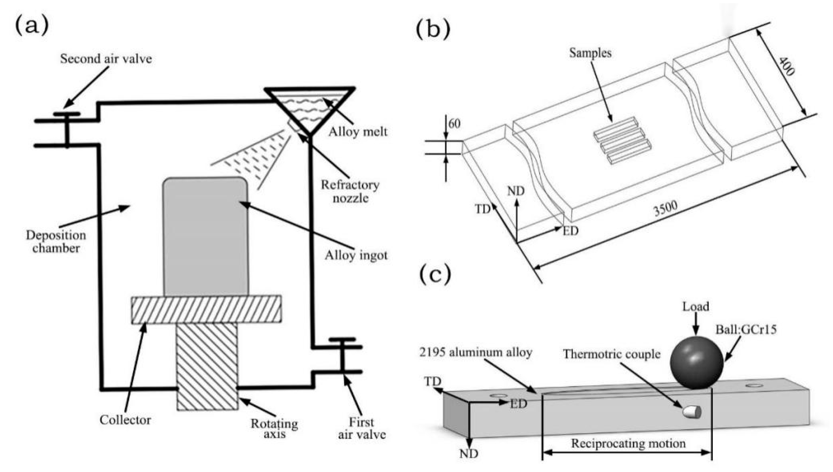
The test samples were extracted from the spray-formed 2195 Al–Li alloy billet. The chemical composition of the billet was Al–3.78 Cu–0.90 Li–0.56 Mg–0.34 Ag–0.11 Zr. Figure 1a shows the schematics of the spray forming technique used in this study. The raw materials were aluminum (99.996% purity), copper (99.99% purity), silver (99.99% purity), Al–10 Li, Al–10 Zr, and Al–50 Mg master alloys. An Osprey spray casting system with a 2000 kg aluminum melt capacity was used. The raw materials were melted in an inductively heated crucible in an Ar inert atmosphere. At 750 ℃, the melt was fed into a two-stage atomizer and atomized by an argon jet with a high flow rate and pressure. The spray was collected on a rotating steel collecting plate and gradually solidified into a preform. The rotation rate of the collecting plate was 40 rpm, and the deposition rate was 15 kg/min. The dimensions of the preformed billet were 650 mm in diameter and 1800 mm in length. No macroscopic defects were found in the plate, such as thermal tearing or rough shrinkage.
2.2. Processing
After forming, the billet was homogenized at 450 °C for 10 h. The billet was machined to a diameter of 490 mm and a length of 1000 mm. Machining removed surface defects and transformed the billet according to the capacity of the extrusion cylinder. Hot extrusion was conducted using a horizontal extruder (80 MN (meganewton), Taiyuan Heavy Industry CO., LTD., Taiyuan, China) to obtain the plate with a cross-section size of 400 mm × 60 mm. The diameter of the extrusion cylinder was 500 mm. The extrusion ratio was 8.17, and the dummy block speed was 0.1 mm/s. The extrusion cylinder and mold temperatures were 460 °C and 420 °C, respectively. After extrusion, the samples were cut by wire-electrode cutting. To avoid the influence of microstructure heterogeneity, all samples were extracted from the center of the plate. The sampling position and its relationship with the extrusion direction are shown in Figure 1b. The samples were solution treated before testing at a heating rate of 4.25 °C/min. The temperature was kept at 510 °C for 2 h. At the end of the solution treatment, water quenching was performed at 60 °C. Then, the samples were aged at 170 °C for 28 h (T6) and cooled in air.
2.3. Analysis and Characterization
Optical microscopy (OM, DMI5000M, Leica Microsystems, Weitzlar, Germany) was used to analyze the morphology of the extruded plate. The OM samples were mechanically polished with different sandpapers and flannels. A cotton ball dipped in Kellar’s reagent (1 mL HF + 1.5 mL HCl + 2.5 mL HNO3 + 95 mL H2O) was used to wipe the polished surface for 35 s. The morphology and type of the second phase were identified via transmission electron microscopy (TEM, HT-7700, Hitachi High-tech Company, Tokyo, Japan). The acceleration voltage was 200 kV. For the TEM analysis, a plasma ion polisher (Model 691, Gatan, CA, USA) was used to prepare thin foils with a thickness of 80 nm. The sliding dry friction and wear properties of the alloy were tested using a reciprocating friction and wear testing machine (MWF-05, Shandong Baohang Machine Equipment Manufacturing Co., Ltd., Jinan, China).
The ball-on-disk wear tests were conducted under dry conditions at a standard temperature (~25 °C). A high carbon chromium-bearing steel ball (GCr15, φ6 mm) was used because of its high hardness (~63 HRC) and the fact that it can concentrate a significant amount of wear on the alloy surface. A wide range of loads was applied during the pre-test to thoroughly evaluate the Al–Li alloy wear phenomena. However, it is difficult to accurately predict the wear rate under small loads, whereas excessively high loads cause the instability of the friction process. Based on the tests, the optimal experimental load range was 2–40 N. The stroke and frequency were kept constant at 15 mm and 2.5 Hz, respectively. The sliding distance was 55 m, and the sliding direction was parallel to the extrusion direction. The positional relationship between the friction contact surface and the extruded plate is shown in Figure 1c. The samples were cleaned with alcohol and distilled water and dried in chilled air.
After the wear test, the three-dimensional (3D) topographic images of the worn surface were acquired via laser scanning confocal microscopy (LSM900, ZEISS, Oberkochen, Germany). The volume (mm3) of the worn-out material was calculated using the software provided by the confocal measurement system. The specific wear rate (mm3·m−1) was calculated using the following equation:
where s (m) is the total sliding distance. The friction tests were repeated six times under each loading condition and then averaged to obtain the final result. The standard deviation was calculated to determine the dispersion of the data. To analyze the wear phenomenon, the morphology of the sliding track was observed via scanning electron microscopy (SEM, Quant FEG 250FEI, FEI, Hillsboro, OR, USA) combined with energy-dispersive spectroscopy (EDS). SEM and EDS were also utilized to observe the debris morphology of the samples. Finally, the worn sample was cut parallel to the sliding direction. After mechanical polishing and chemical corrosion, OM was used to observe the microstructure of the friction-induced deformed layer.
3. Results and Discussion
3.1. Microstructure Analysis before Friction
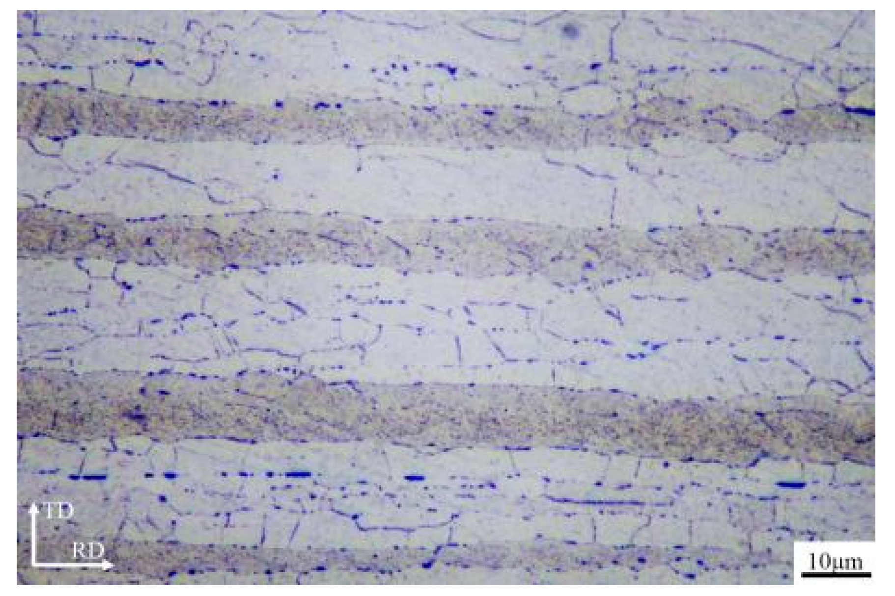
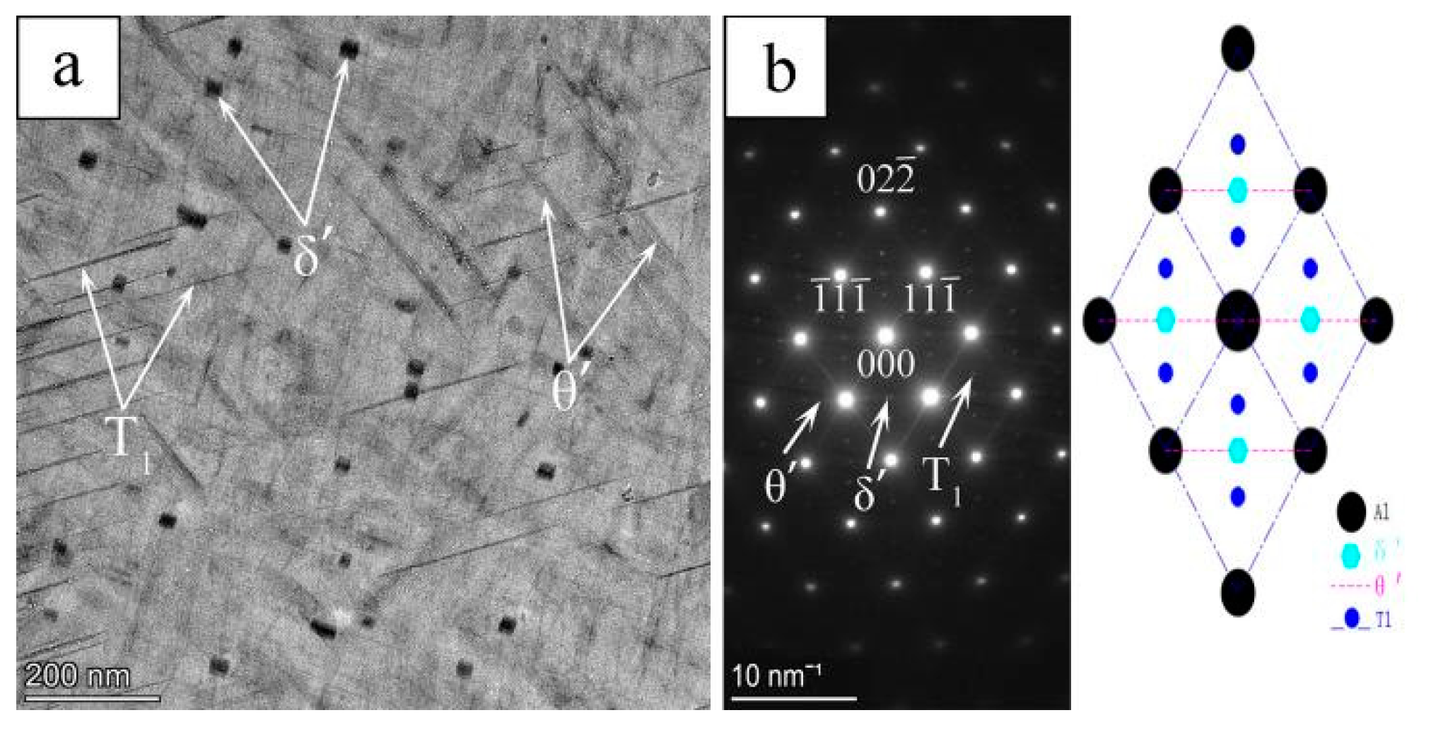
The microstructure behavior of the 2195 Al–Li plate after the heat treatment is shown in Figure 2. It can be observed that the aluminum plate was fully recrystallized with marginally elongated grains. The size of the recrystallized grains ranges from 5 to 12 µm. TEM was used to analyze the morphology and the precipitated phase. The results are shown in Figure 3. Figure 3a shows the brightfield (BF) images of the alloy microstructure. Figure 3b shows the selected area electron diffraction (SAED) pattern. It can be observed that there are three types of fine second phases in the alloy, namely the needle-like phases T1(Al2CuLi) and θ′(Al2Cu), and the spherical phase δ′(Al3Li). Similar findings have been reported by Yang et al. [21,22].
3.2. Results of the Friction and Wear Experiment
3.2.1. Coefficient of Friction and Wear Rate
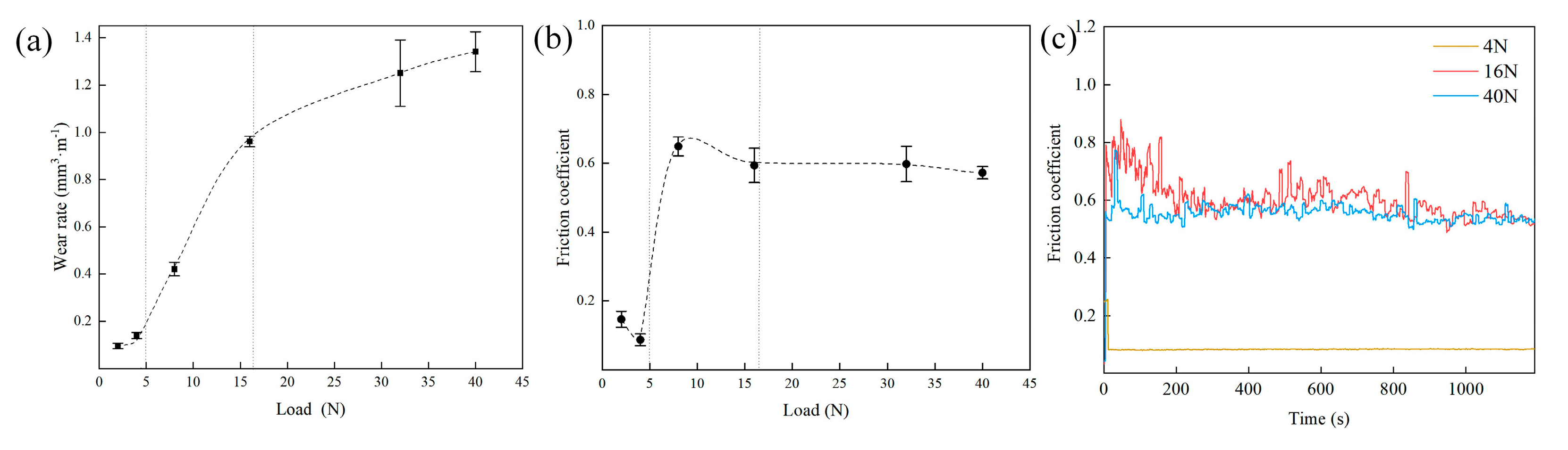
The friction coefficient and wear rate of the 2195 Al–Li alloy as a function of the applied load are shown in Figure 4. In Figure 4a, the wear rate of the alloy shows three different stages: the stage in which it increases slowly at a low load (Stage I, 2−4 N), the stage in which it increases rapidly at a medium load (Stage II, 8–16 N), and the final stage in which it increases gradually to the highest level (Stage III, 32−40 N). At 2−4 N, the wear rate is about 0.1 mm3·m−1. When the load increases from 4 to 16 N, although the load rises by a factor of 3, the wear rate increases by a factor of 10 (0.96 mm3·m−1). With increasing load, the increase in the wear rate is reduced. At 40 N, the wear rate reaches its maximum value of 1.34. Figure 4b,c show that the friction coefficient of the alloy is minimal and stable in Stage 1 (2−4 N), about 0.1. However, during the second and third stages (8−40 N), the friction coefficient rises rapidly to about 0.6. At the same time, the friction coefficient fluctuates dramatically, which means the wear process becomes unstable.
3.2.2. Wear Phenomenon
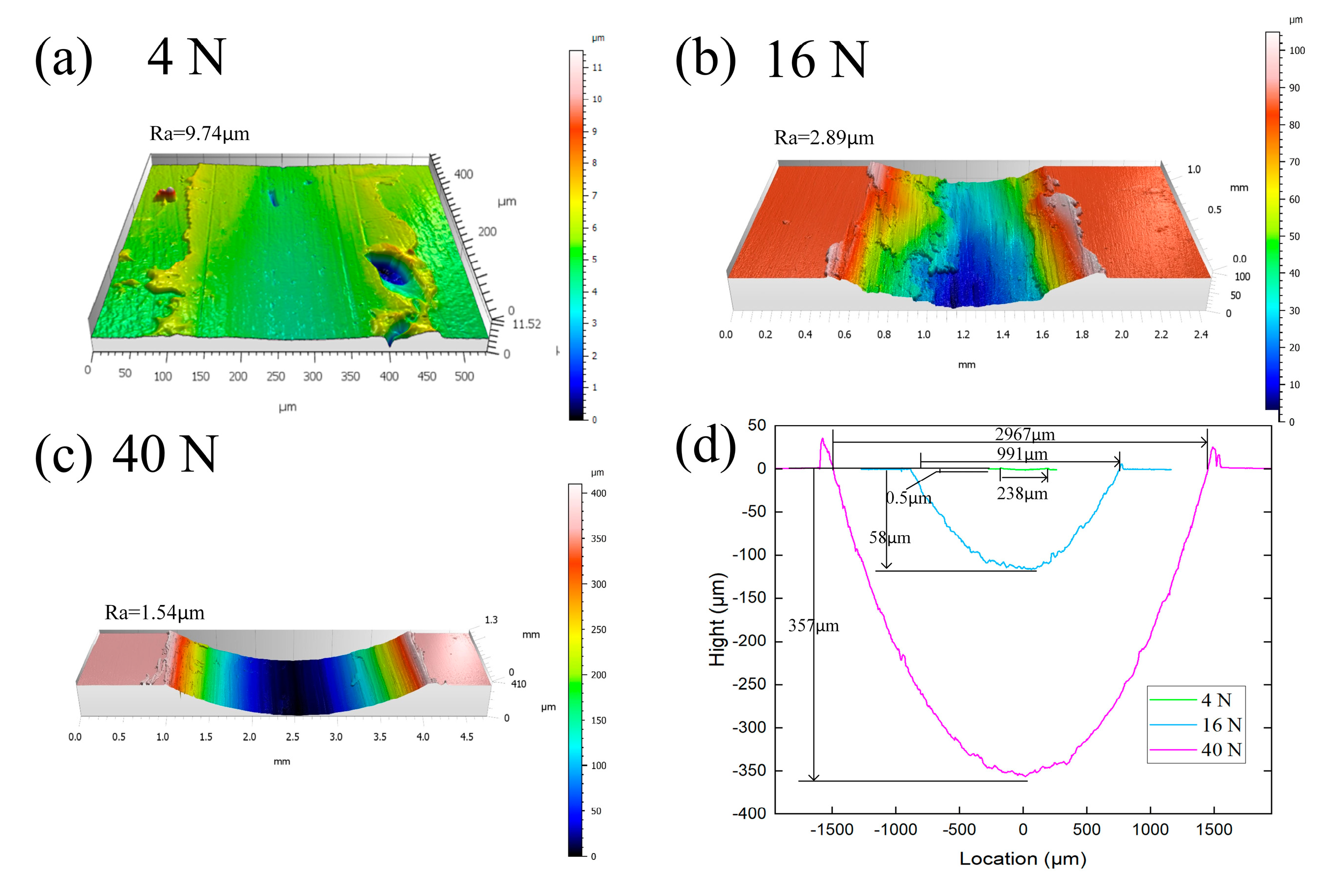
The 3D profilometry analysis results of the standard samples are shown in Figure 5. For simplicity, only the samples tested at 4 N (Stage I), 16 N (Stage II), and 40 N (Stage III) were selected as the representatives. The color change shown in the figure corresponds to the variation in the wear track depth. The line profile of the surfaces shows that the width and depth of the abrasion mark increase exponentially with the applied load. At 4 N, the width of the abrasion mark is 238 μm, and the depth is 0.5 μm. However, when the load increases to 16 N, the width and depth rapidly increase to 991 and 58 μm, respectively. By increasing the load to 40 N, the width and depth of the abrasion mark reach 2967 and 357 μm, respectively. This change indicates that the increased load causes the sliding ball to push away more metal, which causes an increase in the sliding resistance and friction coefficient. The significant difference in wear volume is related to the wear behavior of metals under different loads. The wear surface morphology was observed using SEM under loads of 2–40 N for a comprehensive understanding, as shown in Figure 6a–f.
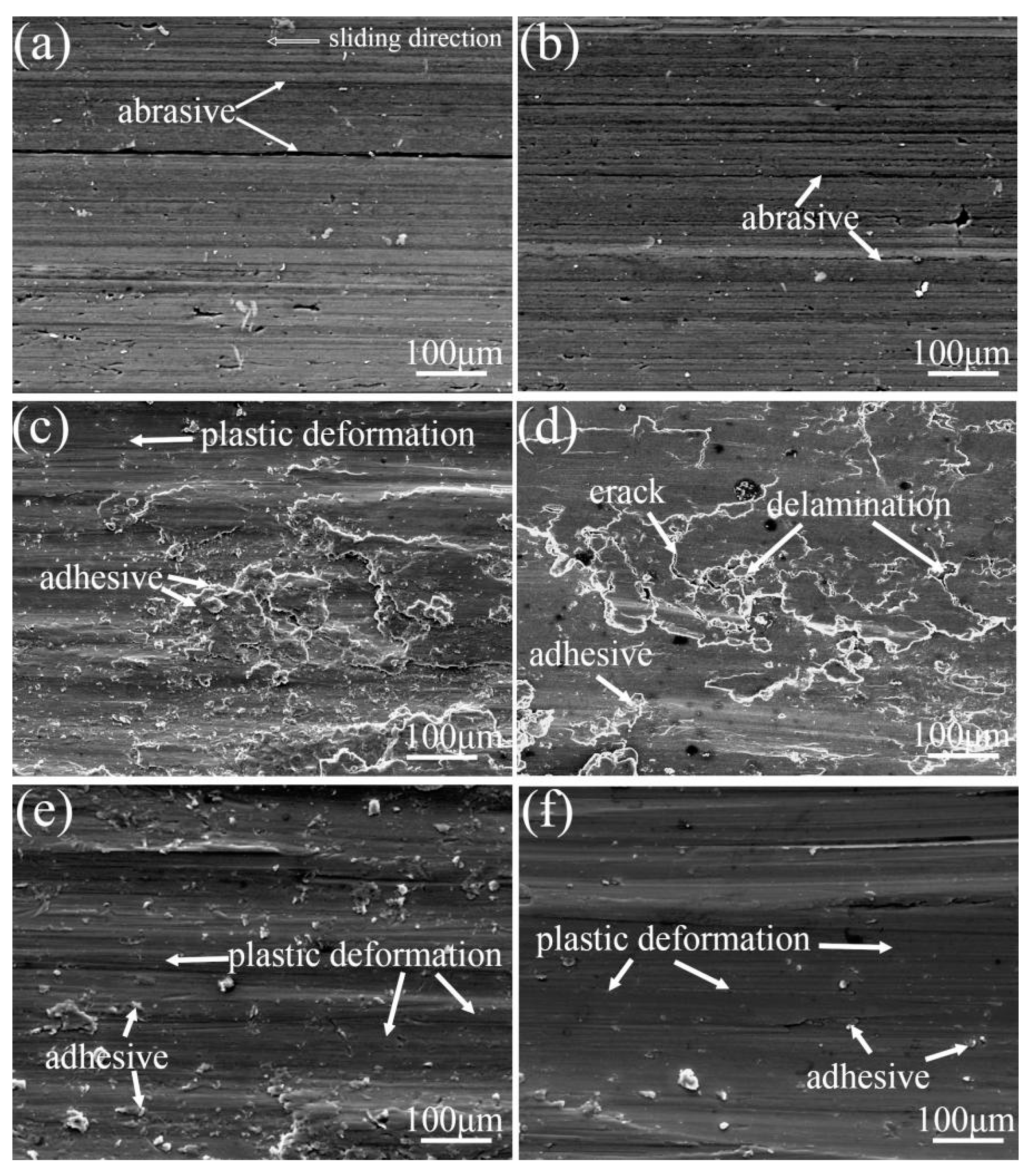
Stage 1: Due to the abrasive wear, grooves and scratches can be observed on the matrix for an experimental load of 2−4 N (Figure 6a,b). The figure shows that the morphology is affected by wear debris particles formed during friction and hard microscopic bumps on the paired ball surface [25]. Suresha et al. [26] explained that the size of the micro-bumps on the surface of the tribo-pair material influences the wear rate more than the applied load. Considering this effect, it can be assumed that in the present study the wear rate of the 2195 Al−Li alloy increases slowly in Stage 1.
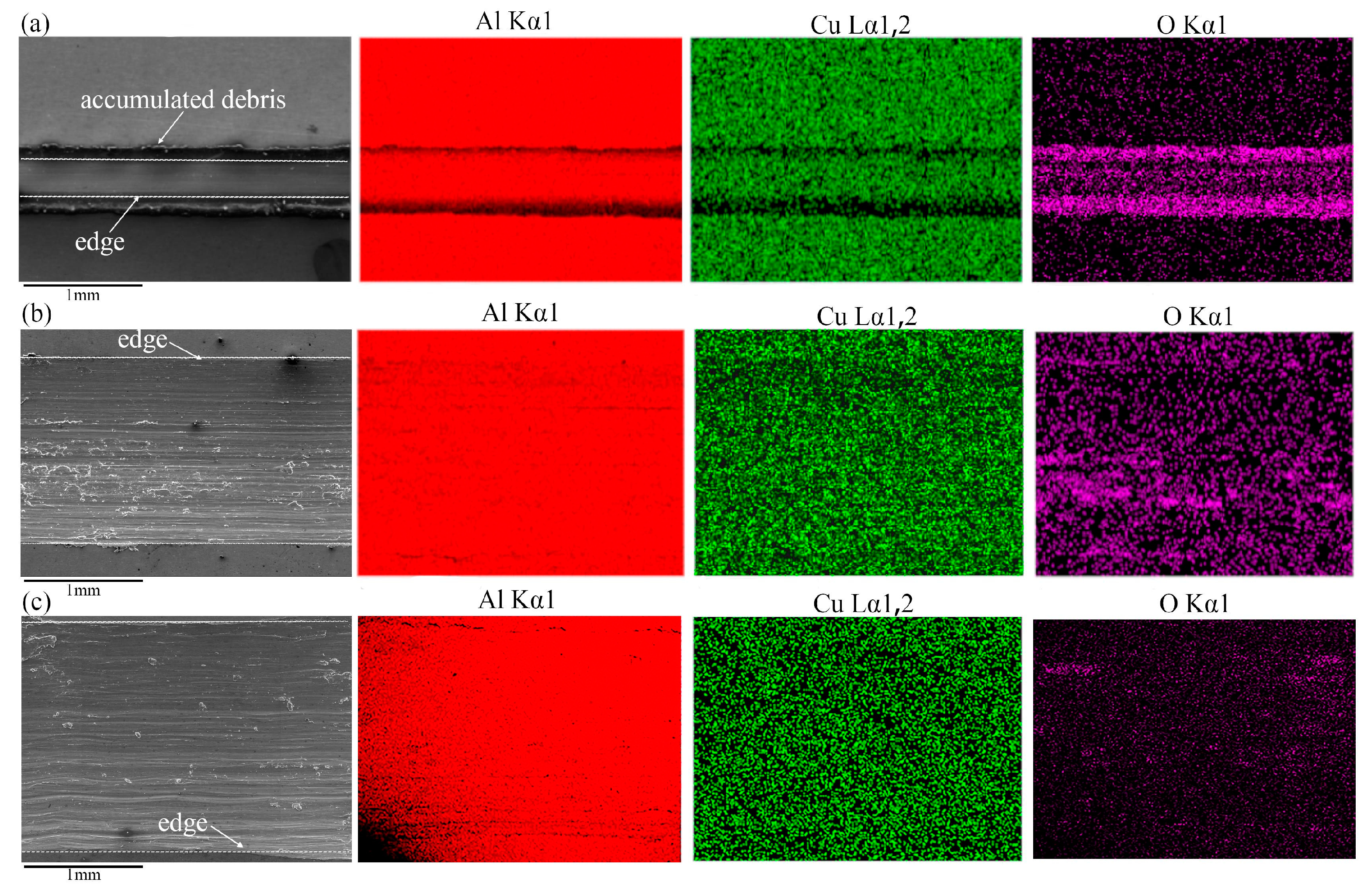
The oxygen composition of the worn surface was analyzed via EDS. This is shown in Figure 7. It can be observed that at 2 and 4 N, an excessive amount of elemental oxygen appears on the surface of the alloy after being worn (Table 1). This phenomenon indicates that an oxide film is formed on the metal surface during the friction of the alloy. Then, the oxide film instantly breaks and generates debris under the action of cyclic contact stress. The continuous formation and detachment of the oxide film are regarded as oxidation wear [27]. Many models have been proposed to explain the oxidative wear of metals [28,29]. These models use different parameters and conditions; however, these are based on the same assumption that the behavior of the oxide film affects the oxidative wear process. Quinn [30] proposed the oxidation wear model of steel considering the light wear stage:
where ωL represents the wear rate, ξ is the maximum thickness of the accumulating oxide film, d is the relative sliding distance between the two metals, W is the applied load, A is the rate constant of Arrhenius’s empirical formula, Q is the activation energy of the metal oxidation reaction, R is the ideal gas constant, T is the temperature of the contact surfaces, ρ is the oxide density, V is the sliding velocity, and pm is the yield pressure of the softer metal. From Equation (2), it can be inferred that when the 2195 Al–Li alloy is in Stage 1, the material loss caused by oxidative wear is positively correlated with the load W and the temperature T. An increase in the applied load results not only in an increase in W but also in an increase in T because of the accumulation of friction heat. Therefore, in Stage 1, an increased loading can increase the contribution of oxidative wear.
Stage 2: Under the normal loads of 8 and 16 N, the wear phenomenon of the alloy was the same. The SEM images shown in Figure 6c,d indicate the presence of patches of re-deposited material and adhesive wear. In the adhesion and sliding processes, strong ionic and covalent bonds form between the micro-convex bodies of the friction pairs, increasing the friction coefficients. The wear volume can be calculated according to the following expression [31]:
where V is the wear volume, n is the number of wear elements generated in the microscopic contact area where adhesion occurs, and a and b are the mean radius of the microscopic bumps of the wear materials and tribo-paired materials, respectively. P is the applied load, and Pm is the yield stress of the wear material (the softer material). τ is the sliding distance, and λ is a constant determined by the chemisorption capacity of the surrounding molecules. From the wear volume expression, it is clear that the volume of material loss caused by adhesive wear is proportional to the applied load and sliding distance. Therefore, when the wear of the 2195 Al–Li alloy enters Stage 2, the contribution of adhesion to the wear may increase with increasing load.
The area outside the adhesive wear is smooth, indicating that the metal undergoes plastic deformation under the combined effect of a high load and frictional heat. The continuously accumulating heat at the contact surface causes thermal softening, increasing the alloy plasticity and generating a smooth surface. This is referred to as severe plastic deformation [32]. The wear phenomenon makes the alloy prone to plastic deformation and failure when subjected to micro-plowing. As a result, the surface alloy is pulled out of the friction contact surface and is constantly detached, forming large lamellar debris. Zheng et al. [33] studied the surface microstructure of an Al–Zn–Mg–Cu alloy subjected to friction and wear using TEM. The results show that severe plastic deformation causes dense dislocations in the cell walls. Later, micro-lamellae with a high dislocation density are formed, and the equiaxed dislocation cells develop inside the micro-lamellae. Finally, the lamellae are gradually separated into randomly oriented ultrafine grains. Published studies have explained that similar phenomena occur in Inconel and magnesium alloys [34,35].
In addition, spalling and cracking perpendicular to the sliding direction occur under the applied load, which means that the surface layer experiences delamination wear. According to the Hertz contact theory, the maximum shear stress occurs at a certain depth below the surface during the sliding process of the ball [36]. The stress causing plastic deformation in the substrate induces the formation of many dislocations and defects. Greiner et al. elucidated this process via systematic model experiments and discrete dislocation dynamics simulations [37]. This phenomenon is repeated as the sliding proceeds, gradually forming fatigue microcracks and holes in the alloy surface [38].
The EDS analysis reveals that the O element content decreased significantly (Table 1). This behavior can be attributed to the appearance of adhesive and delamination wear, which increase the rate of surface wear failure. As a result, the oxide layer is removed faster than it can form. Different from the low-load conditions (2−4 N), the transformation of the wear phenomenon is a fundamental reason for the rapid increase in the wear rate and the mild−severe wear transition.
Stage 3: A few areas demonstrate adhesive wear characteristics when the load exceeds 30 N (Figure 6e,f). However, most areas of the friction trace become smooth. The results of the surface roughness analysis also confirm this phenomenon (Figure 5). In this stage, the material loss rate is much higher than the oxide film growth rate. The oxygen element content on the alloy-worn surface is reduced to the minimum, as shown in Table 1 and Figure 7. Severe plastic deformation mechanisms dominate the wear of the alloy.
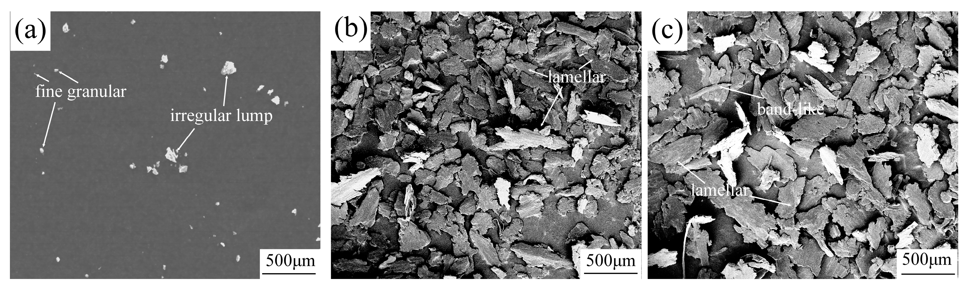
Figure 8 shows the morphology of the wear debris of the 2195 Al–Li alloy under different loads. The samples tested at 4 N (Stage I), 16 N (Stage II), and 40 N (Stage III) were chosen as the representatives. When the experimental load was 4 N, it was observed that the average size of the debris was small. Most of the debris was in the form of fine granular and irregular lumps (Figure 8a). The debris diameter was between 10 and 100 μm. At 16 N, the wear entered the second and third stages. At the same time, the shape of the debris also changed to large lamellae and bands (Figure 9b). It is commonly assumed that fine granular and irregular lumpy debris is produced from abrasive wear. The primary sources of the band-like and lamellar debris are the delamination wear, adhesive wear, and severe plastic deformation mechanisms. Most debris is more than 200 μm in diameter. At 40 N, the shape of the chip does not change appreciably, but the size of the debris increases marginally.
3.2.3. Plastic Deformation Behavior Induced by Friction
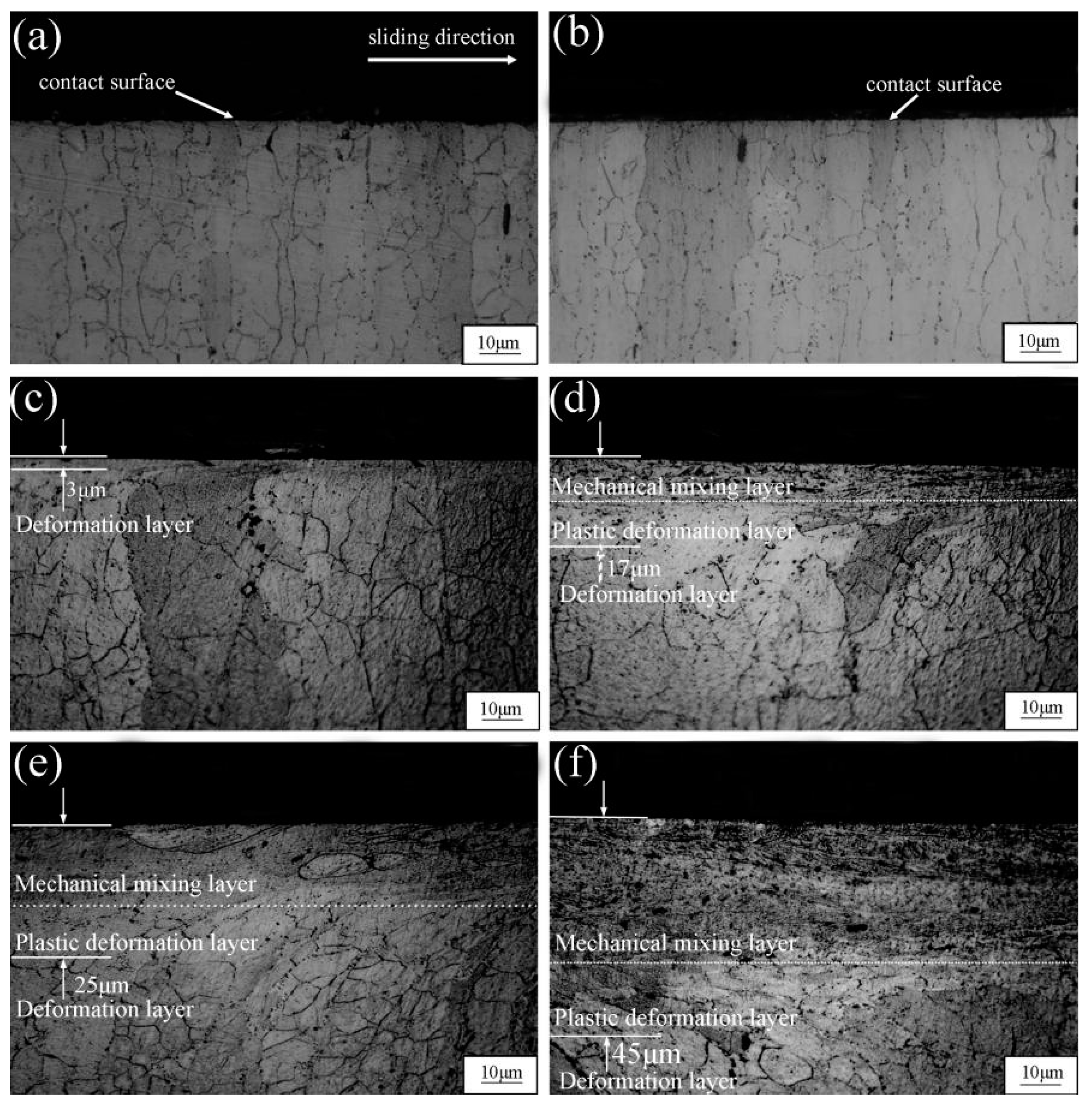
The microstructural evolution of the aluminum alloy during sliding is considered the main factor that changes during the wear phenomenon, determining the wear properties and mild–severe wear transition. Figure 9 shows the microstructural changes of the substrate as a function of the load. Almost no trace of plastic deformation is observed in Stage 1 (Figure 9a,b). After raising the load (Stages 2 and 3), evident plastic deformation occurred in the substrate. The load increases from 8 to 16 N, increasing the plastic deformation zone depth from 3 to 17 μm, as shown in Figure 9a,b. At the same time, layered structures appear in the deformation zone. The plastic deformation of the metal immediately adjacent to the friction contact surface is exceptionally high, resulting in unrecognizable grain boundaries. The zone immediately adjacent to the friction contact surface is usually referred to as the mechanical mixing layer (MML) and is about 10 μm thick. At 32 N, the depths of the deformation zone and the MML increase simultaneously. The thicknesses of the deformation layer and the MML are 25 and 15 μm, respectively. At the same time, cracks extending from the inner metal to the surface appear in the MML. As discussed in Section 3.2.2, crack propagation causes the spalling of the metal, resulting in delamination wear and spalling pits. This behavior is shown in Figure 6. At 40 N, the plastic deformation of the metal increases, and the thickness of the MML region is nearly doubled. The thickness of the deformation layer increases to 45 μm, and the thickness of the MML layer becomes 30 μm.
During sliding, noticeable plastic deformation occurs in the friction contact area of the metal, which changes the microstructure of the surrounding wear marks. This phenomenon has attracted increasing attention from the research community. Studies on Al–Cu and Al–Mg alloys have shown that the resistance of the metal to the formation and shedding of the MML layer during friction determines the wear behavior [39,40]. Chen et al. investigated the friction-induced deformation behavior of Cu–Al alloys. They found that the transition of the dynamic recrystallization structure to the outermost MML plays a vital role in the tribological and wear properties [41]. For Al–Li alloys, the change in microstructure leads to a change in the wear phenomenon from abrasive to layered wear and finally leads to the transition from mild to severe wear. Therefore, if the degree of plastic deformation caused by friction can be reduced via aging strengthening or other strategies, severe wear may be avoided. This is conducive to the improvement in the wear resistance of the alloy.
4. Conclusions
Evaluating the reasons for the mild–severe wear transition is a prerequisite for delaying the occurrence of such a transition. In this work, the mild–severe wear transition of the 2195 Al–Li alloy for different loads was investigated. The analysis in this study shows that controlling the tribo-induced plastic deformation of the 2195 Al–Li alloy should be an important way to delay the occurrence of the mild–severe wear transition. This provides a breakthrough for future research on improving the wear resistance of Al–Li alloys.
The main conclusions of this work are as follows:
- When the load increases from 2 to 40 N, the change in the wear rate can be divided into three stages. In Stage 1 (2–4 N), the wear rate does not change significantly with increasing load. The alloy is in the mild wear regime. In Stages 2 (8–16 N) and 3 (32–40 N), the rate at which the wear rate increases firstly rises rapidly and then is gradually reduced. The alloy is in the severe wear regime;
- The main wear phenomena are abrasion, adhesion, oxidation, delamination, and severe plastic deformation. When the load ranges from 2 to 4 N, the wear is dominated by abrasion and oxidation. At 8 and 16 N, the wear phenomenon changes to adhesion, delamination, and severe plastic deformation. When the load exceeds 32 N, the dominant wear phenomenon is severe plastic deformation;
- The change in the wear phenomenon is affected by the microstructure of the substrate. When the load exceeds 8 N, friction and wear cause plastic deformation of the 2195 Al–Li alloy. The deformation results in the mechanical mixing and the formation of plastic deformation zones near the wear contact surface. By increasing the load, the thickness of the plastic deformation layer rises rapidly.
Author Contributions
Conceptualization, Q.C.; Methodology, Q.C.; Investigation, Q.C., G.M. and X.S.; Resources, Y.Y.; Data curation, Y.Y. and L.L.; Writing–original draft, Y.Y.; Writing–review & editing, Q.C. All authors have read and agreed to the published version of the manuscript.
Funding
This work was supported by Project supported by the Natural Science Foundation of Shandong Provincial, China (ZR2020QE161), the Key Laboratory of Electromagnetic Processing of Materials, Ministry of Education, Northeastern University (NEU-EPM-016).
Data Availability Statement
Not applicable.
Conflicts of Interest
We declare we have no commercial or associative interest representing a conflict of interest in connection with the work submitted.
References
- Zhang, P.; Chen, M. Progress in characterization methods for thermoplastic deforming constitutive models of Al–Li alloys: A review. J. Mater. Sci. 2020, 55, 9828–9847. [Google Scholar] [CrossRef]
- Samal, P.; Vundavilli, P.R.; Meher, A.; Mahapatra, M.M. Recent progress in aluminum metal matrix composites: A review on processing, mechanical and wear properties. J. Manuf. Process. 2020, 59, 131–152. [Google Scholar] [CrossRef]
- Ramezani, M.; Neitzert, T.; Pasang, T.; Sellès, M.A. Frictional Properties of AZ80 and ZE10 Magnesium Alloys under Dry and Lubricated Contact Conditions. Procedia Eng. 2014, 81, 1836–1841. [Google Scholar] [CrossRef]
- Ilie, F. Effect of the Etching on Chemical Mechanical Planarization of the Selective Layer Surface. Int. J. Mater. Sci. Appl. 2017, 6, 193. [Google Scholar] [CrossRef]
- Schütte, M.R.; Ehrich, J.; Linsler, D.; Hanke, S. Effects of Microstructure Modification by Friction Surfacing on Wear Behavior of Al Alloys with Different Si Contents. Materials 2022, 15, 1641. [Google Scholar] [CrossRef] [PubMed]
- Yang, Z.-R.; Sun, Y.; Li, X.-X.; Wang, S.-Q.; Mao, T.-J. Dry sliding wear performance of 7075 Al alloy under different temperatures and load conditions. Rare Met. 2015, 41, 1057–1062. [Google Scholar] [CrossRef]
- Tarasov, S.Y.; Filippov, A.; Kolubaev, E.; Kalashnikova, T. Adhesion transfer in sliding a steel ball against an aluminum alloy. Tribol. Int. 2017, 115, 191–198. [Google Scholar] [CrossRef]
- Singh, J. Fabrication characteristics and tribological behavior of Al/SiC/Gr hybrid aluminum matrix composites: A review. Friction 2016, 4, 191–207. [Google Scholar] [CrossRef]
- Hatamleh, O. A comprehensive investigation on the effects of laser and shot peening on fatigue crack growth in friction stir welded AA 2195 joints. Int. J. Fatigue 2009, 31, 974–988. [Google Scholar] [CrossRef]
- Nayan, N.; Gurao, N.P.; Murty, S.N.; Jha, A.K.; Pant, B.; Sharma, S.; George, K.M. Microstructure and micro-texture evolution during large strain deformation of an aluminium–copper–lithium alloy AA 2195. Mater. Des. 2015, 65, 862–868. [Google Scholar] [CrossRef]
- Wang, X.-H.; Wang, J.-H.; Yue, X.; Gao, Y. Effect of aging treatment on the exfoliation corrosion and stress corrosion cracking behaviors of 2195 Al–Li alloy. Mater. Des. 2015, 67, 596–605. [Google Scholar] [CrossRef]
- Cheng, Y.-L.; Cao, J.-H.; Mao, M.-K.; Peng, Z.-M.; Skeldon, P.; Thompson, G. High growth rate, wear resistant coatings on an Al–Cu–Li alloy by plasma electrolytic oxidation in concentrated aluminate electrolytes. Surf. Coat. Technol. 2015, 269, 74–82. [Google Scholar] [CrossRef]
- Li, G.; Hao, S.; Gao, W.; Lu, Z. The Effect of Applied Load and Rotation Speed on Wear Characteristics of Al-Cu-Li Alloy. J. Mater. Eng. Perform. 2022, 31, 5875–5885. [Google Scholar] [CrossRef]
- Davoudi, M.; Nejad, A.F.; Koloor, S.S.R.; Petrů, M. Investigation of effective geometrical parameters on wear of hot forging die. J. Mater. Res. Technol. 2021, 15, 5221–5231. [Google Scholar] [CrossRef]
- Archard, J.F.; Hirst, W. The wear of metals under unlubricated conditions. Proc. R. Soc. London. Ser. A Math. Phys. Sci. 1956, 236, 397–410. [Google Scholar] [CrossRef]
- Yin, C.-H.; Liang, Y.-L.; Liang, Y.; Li, W.; Yang, M. Formation of a self-lubricating layer by oxidation and solid-state amorphization of nano-lamellar microstructures during dry sliding wear tests. Acta Mater. 2018, 166, 208–220. [Google Scholar] [CrossRef]
- Banerji, A.; Edrisy, A.; Francis, V.; Alpas, A. Effect of bio-fuel (E85) addition on lubricated sliding wear mechanisms of a eutectic Al–Si alloy. Wear 2014, 311, 1–13. [Google Scholar] [CrossRef]
- Wu, X.; Wang, D.; De Andrade, V.; Jiang, Y.; Wang, W.; Wen, S.; Gao, K.; Huang, H.; Chen, S.; Nie, Z. Dry sliding wear of microalloyed Er-containing Al–10Sn–4Si–1Cu alloy. J. Mater. Res. Technol. 2020, 9, 14828–14840. [Google Scholar] [CrossRef]
- Al-Qutub, A.; Khalil, A.; Saheb, N.; Hakeem, A. Wear and friction behavior of Al6061 alloy reinforced with carbon nanotubes. Wear 2012, 297, 752–761. [Google Scholar] [CrossRef]
- Zhang, Q.; Zhang, C.; Lin, J.; Zhao, G.; Chen, L.; Zhang, H. Microstructure analysis and low-cycle fatigue behavior of spray-formed Al–Li alloy 2195 extruded plate. Mater. Sci. Eng. A 2018, 742, 773–787. [Google Scholar] [CrossRef]
- Yang, Y.; Lian, X.; Zhou, K.; Li, G. Effects of laser shock peening on microstructures and properties of 2195 Al-Li alloy. J. Alloys Compd. 2018, 781, 330–336. [Google Scholar] [CrossRef]
- Yang, Y.; Zhou, K.; Li, G. Surface gradient microstructural characteristics and evolution mechanism of 2195 aluminum lithium alloy induced by laser shock peening. Opt. Laser Technol. 2018, 109, 1–7. [Google Scholar] [CrossRef]
- Prabhu, M.S.; Perumal, A.E.; Arulvel, S. Development of multi-pass processed AA6082/SiCp surface composite using friction stir processing and its mechanical and tribology characterization. Surf. Coat. Technol. 2020, 394, 125900. [Google Scholar] [CrossRef]
- Chen, Q.; Yu, Y.; Sun, J.; Jing, C.; Zhao, Y.; Wang, J. Investigation of the Wear Behavior of Surface Welding AZ91 and AZ91+Gd Alloys under Variable Loading Conditions. Crystals 2021, 11, 554. [Google Scholar] [CrossRef]
- Zhao, Z.; Zhang, L.; Bai, P.; Du, W.; Wang, S.; Xu, X.; Dong, Q.; Li, Y.; Han, B. Tribological Behavior of In Situ TiC/Graphene/Graphite/Ti6Al4V Matrix Composite Through Laser Cladding. Acta Met. Sin. Engl. Lett. 2021, 34, 1317–1330. [Google Scholar] [CrossRef]
- Suresha, B.; Seetharamu, S.; Kumaran, P.S. Investigations on the influence of graphite filler on dry sliding wear and abrasive wear behaviour of carbon fabric reinforced epoxy composites. Wear 2009, 267, 1405–1414. [Google Scholar] [CrossRef]
- Cui, Y.; Shen, J.; Manladan, S.M.; Geng, K.; Hu, S. Wear resistance of FeCoCrNiMnAlx high-entropy alloy coatings at high temperature. Appl. Surf. Sci. 2020, 512, 145736.1–145736.14. [Google Scholar] [CrossRef]
- JWilson, J.E.; Stott, F.H.; Wood, G.C. The development of wear-protective oxides and their influence on sliding friction. Proc. R. Soc. Lond. Ser. A Math. Phys. Sci. 1980, 369, 557–574. [Google Scholar] [CrossRef]
- Quinn, T. The oxidational wear of low alloy steels. Tribol. Int. 2002, 35, 691–715. [Google Scholar] [CrossRef]
- Quinn, T.F.J. The Effect of “Hot-Spot” Temperatures on the Unlubricated Wear of Steel. ASLE Trans. 1967, 10, 158–168. [Google Scholar] [CrossRef]
- Mishina, H.; Hase, A. Wear equation for adhesive wear established through elementary process of wear. Wear 2013, 308, 186–192. [Google Scholar] [CrossRef]
- Wang, Y.B.; Li, L.; An, J. Dry wear behavior and mild-to-severe wear transition in an Mg-Gd-Y-Zr alloy. Surf. Topogr. Metrol. Prop. 2021, 9, 25032. [Google Scholar] [CrossRef]
- Zheng, G.; Luo, X.; Yang, Y.; Kou, Z.; Huang, B.; Zhang, Y.; Zhang, W. The gradient structure in the surface layer of an Al-Zn-Mg-Cu alloy subjected to sliding friction treatment. Results Phys. 2019, 13, 102318. [Google Scholar] [CrossRef]
- Xin, L.; Yang, B.; Wang, Z.; Li, J.; Lu, Y.; Shoji, T. Microstructural evolution of subsurface on Inconel 690TT alloy subjected to fretting wear at elevated temperature. Mater. Des. 2016, 104, 152–161. [Google Scholar] [CrossRef]
- Zhang, W.; Lu, J.; Huo, W.; Zhang, Y.; Wei, Q. Microstructural evolution of AZ31 magnesium alloy subjected to sliding friction treatment. Philos. Mag. 2018, 98, 1576–1593. [Google Scholar] [CrossRef]
- Machado, M.; Moreira, P.; Flores, P.; Lankarani, H.M. Compliant contact force models in multibody dynamics: Evolution of the Hertz contact theory. Mech. Mach. Theory 2012, 53, 99–121. [Google Scholar] [CrossRef]
- Greiner, C.; Gagel, J.; Gumbsch, P. Solids Under Extreme Shear: Friction-Mediated Subsurface Structural Transformations. Adv. Mater. 2019, 31, e1806705. [Google Scholar] [CrossRef] [PubMed]
- Alidokht, S.; Abdollah-Zadeh, A.; Assadi, H. Effect of applied load on the dry sliding wear behaviour and the subsurface deformation on hybrid metal matrix composite. Wear 2013, 305, 291–298. [Google Scholar] [CrossRef]
- Mandal, M.; Mitra, R. Study of Dry Sliding Wear Behavior of Hot-Rolled and Mushy-State Rolled Al-4.5Cu-5TiB2 In-Situ Composite with Analysis of Work Hardening and Subsurface Microstructure-Microtexture Evolution Using EBSD. Met. Mater. Trans. A 2019, 50, 5356–5372. [Google Scholar] [CrossRef]
- Hariharasakthisudhan, P.; Jose, S.; Manisekar, K. Dry sliding wear behaviour of single and dual ceramic reinforcements premixed with Al powder in AA6061 matrix. J. Mater. Res. Technol. 2019, 8, 275–283. [Google Scholar] [CrossRef]
- Chen, X.; Han, Z.; Lu, K. Wear mechanism transition dominated by subsurface recrystallization structure in Cu–Al alloys. Wear 2014, 320, 41–50. [Google Scholar] [CrossRef]
Figure 1.
Schematics of (a) The spray forming process, (b) Extruded plate and sample position, and (c) Friction and wear experiment.
Figure 1.
Schematics of (a) The spray forming process, (b) Extruded plate and sample position, and (c) Friction and wear experiment.

Figure 2.
OM image of the 2195 Al–Li alloy.

Figure 3.
TEM microstructure of the 2195 Al–Li extruded plate: (a) BF image and (b) Corresponding SAED pattern.
Figure 3.
TEM microstructure of the 2195 Al–Li extruded plate: (a) BF image and (b) Corresponding SAED pattern.

Figure 4.
(a) Wear rate and (b) Friction coefficient of the 2195 Al–Li alloy under different loads; (c) Friction coefficient as a function of time.
Figure 4.
(a) Wear rate and (b) Friction coefficient of the 2195 Al–Li alloy under different loads; (c) Friction coefficient as a function of time.

Figure 5.
(a–c) 3D wear track surface profiles of the 2195 Al–Li alloy and (d) Typical cross-sectional profiles of the wear tracks. The sliding direction is perpendicular to the screen.
Figure 5.
(a–c) 3D wear track surface profiles of the 2195 Al–Li alloy and (d) Typical cross-sectional profiles of the wear tracks. The sliding direction is perpendicular to the screen.

Figure 6.
Morphology of the worn surface: (a) 2 N, (b) 4 N, (c) 8 N, (d) 16 N, (e) 32 N, and (f) 40 N.
Figure 6.
Morphology of the worn surface: (a) 2 N, (b) 4 N, (c) 8 N, (d) 16 N, (e) 32 N, and (f) 40 N.

Figure 7.
Wear surface morphology of the 2195 Al–Li alloy and EDS mapping analysis: (a) 4 N, (b) 16 N, and (c) 40 N.
Figure 7.
Wear surface morphology of the 2195 Al–Li alloy and EDS mapping analysis: (a) 4 N, (b) 16 N, and (c) 40 N.

Figure 8.
Wear debris morphology of the 2195 Al–Li alloy: (a) 4 N, (b) 16 N, and (c) 40 N.

Figure 9.
Microstructure of the region near the wear mark: (a) 2 N, (b) 4 N, (c) 8 N, (d) 16 N, (e) 32 N, and (f) 40 N.
Figure 9.
Microstructure of the region near the wear mark: (a) 2 N, (b) 4 N, (c) 8 N, (d) 16 N, (e) 32 N, and (f) 40 N.


Table 1.
EDS surface scanning analysis results (wt%).
| Element Content (wt%) | Al | Cu | O |
|---|---|---|---|
| Tested at 4 N | 91.18 | 4.55 | 4.27 |
| Tested at 16 N | 93.29 | 4.71 | 2.00 |
| Tested at 40 N | 94.02 | 4.68 | 1.30 |
Disclaimer/Publisher’s Note: The statements, opinions and data contained in all publications are solely those of the individual author(s) and contributor(s) and not of MDPI and/or the editor(s). MDPI and/or the editor(s) disclaim responsibility for any injury to people or property resulting from any ideas, methods, instructions or products referred to in the content. |
© 2023 by the authors. Licensee MDPI, Basel, Switzerland. This article is an open access article distributed under the terms and conditions of the Creative Commons Attribution (CC BY) license (https://creativecommons.org/licenses/by/4.0/).
Share and Cite
MDPI and ACS Style
Chen, Q.; Yu, Y.; Ma, G.; Sun, X.; Lu, L. Dry Sliding Wear Behavior and Mild–Severe Wear Transition of the AA2195-T6 Alloy under Different Loads. Crystals 2023, 13, 698. https://doi.org/10.3390/cryst13040698
AMA Style
Chen Q, Yu Y, Ma G, Sun X, Lu L. Dry Sliding Wear Behavior and Mild–Severe Wear Transition of the AA2195-T6 Alloy under Different Loads. Crystals. 2023; 13(4):698. https://doi.org/10.3390/cryst13040698
Chicago/Turabian StyleChen, Qingqiang, Yalei Yu, Guanjie Ma, Xingzi Sun, and Laixiao Lu. 2023. "Dry Sliding Wear Behavior and Mild–Severe Wear Transition of the AA2195-T6 Alloy under Different Loads" Crystals 13, no. 4: 698. https://doi.org/10.3390/cryst13040698
Note that from the first issue of 2016, this journal uses article numbers instead of page numbers. See further details here.