1. Introduction
Shot peening techniques have been widely used in industry to improve material properties, especially fatigue life. Traditional mechanical shot peening utilizes solid balls to impinge the surface of a part, producing a large plastic deformation and introducing residual compressive stresses on the surface of that part; thus, improving its resistance to crack initiation and propagation [
1,
2]. On the other hand, however, this technique is characterized by severe pollution and large surface roughness. The resultant larger roughness facilitates stress concentrations on the surface, causing a significant reduction in its fatigue resistance and uneven deformation of the treated specimens [
3]. Therefore, traditional mechanical shot peening is increasingly unable to meet the processing requirements of modern industry.
In the past few decades, a series of new peening processes have been derived from mechanical peening in order to overcome these limitations, including laser shock peening (LSP), water jet peening (WJP) and cavitation water jet peening (CWJP). LSP can produce high dislocation density, significant grain refinement and high-peak residual compressive stress on the surface of parts; thus, effectively improving the mechanical properties of these parts [
4,
5,
6]. However, it requires a long processing time and expensive equipment. WJP, which employs high-speed water droplets as the peening media, has achieved good results in introducing residual compressive stresses on metal surfaces. WJP has many advantages over conventional mechanical attrition treatments, such as small surface roughness and low industrial pollution [
7,
8,
9]. However, the driving pressure requirement of the high-pressure pure water jet peening is more than 200 MPa, which is an order of magnitude higher than that required for CWJP, causing excessive energy consumption.
CWJP is an innovative jet technology that uses the shear effect of a high-speed jet in a submerged environment to produce cavitation bubbles in order to greatly improve the impact performance [
10,
11]. After an impingement by a cavitation water jet, the surface properties of materials can be improved to a certain extent, and a certain thickness of strengthening layer will be formed on the surface of the materials. The existence of a residual compressive stress field near the surface of a material can balance the tensile stress generated on the surface of that material during the stressing process, as well as inhibit the initiation of cracks on the surface and subsurface of the material, reduce the expansion speed of cracks and, finally, improve fatigue life [
12,
13]. Soyama et al. first investigated the cavitation water jet in terms of improving the surface performance of parts and components and found that the residual compressive stress on the surface of parts and components after a cavitation water jet treatment has been significantly improved. Since then, the application of shot peening to the surface treatment of materials has become more and more extensive [
14,
15,
16]. Hutli et al. verified that the cavitation water jet is an effective method to improve the surface properties of materials, and the force generated by the cavitation can change the surface roughness of materials on the nanoscale and micron scale [
17,
18]. Tsuda et al. used CWJP to treat steel gear shafts with complex shapes and structures. By analyzing and comparing the residual stress field on the surface of the parts before and after peening, the results show that CWJP can effectively enhance the residual compressive stress value on the material surface [
19]. Masataka et al. investigated the strain-hardening effect of CWJP. It was found that CWJP can improve the hardness of pure aluminum at the surface and subsurface layers and introduce pressurized residual stress to enhance the fatigue strength [
20,
21]. He et al. used CWJP to strengthen a TC4 titanium alloy. The experiments and mechanism studies were carried out by means of macroscopic and microscopic morphologies, metallographic structures, XRD analyses, microhardness and residual stress methods [
22].
In this paper, CWJP was used to strengthen the surface of the 7075 aluminum alloy. The effects of CWJP at different scanning speeds on its morphology, roughness and mechanical properties were investigated. The distribution of the residual stress and microhardness along the depth direction were measured before and after the CWJP treatment. The microstructure evolution of the 7075 aluminum alloy (Al7075) during the CWJP was studied and discussed. The mechanism of grain refinement of the Al7075 during plastic deformation was systematically revealed. Therefore, CWJP can effectively improve the surface properties of the 7075 aluminum alloy.
2. Experimental Procedures
2.1. Materials and Methods
The CWJP device equipped with an Italian AR high-pressure piston pump (AR, Italian), which can provide a pressure for the jet of up to 50 MPa, a rated speed of 1450 r/min and a flow rate of 15 L/min, is shown in
Figure 1a. The high-pressure pipeline is equipped with a pressure relief valve and a pressure gauge for safety. The piston pump pressure is 20 MPa, and an organ pipe nozzle with a flare is applied in this study, which is fixed on a three-axis sliding table.
The material used in this study was Al7075 (China), and the dimensions of the specimens were 100 mm × 100 mm × 3 mm. The chemical composition of the Al7075 is shown in
Table 1. The specimens were heat-treated and polished before the CWJP. The annealing of these specimens was undertaken at a temperature of 510 °C for 3 h in atmosphere, after which these samples were placed at room temperature for a complete air-cooling. It should be noted that the specimens were fixed on a horizontal platform below the nozzle by a fixture, and the nozzle axis was perpendicular to the platform. During the CWJP process, the nozzle was moved along a defined path by controlling the slide, and the scanning speeds were 1, 0.5 and 0.1 mm/min. For convenience, the specimens treated with the CWJP at the scanning speeds of 0.1 mm/min, 0.5 mm/min and 1 mm/min were defined as 1.0_CWJP, 0.5_CWJP and 0.1_CWJP, respectively. Additionally, the original specimen without a CWJP treatment was marked as unCWJP. The detailed scanning position and peening area of the cavitation jet are shown in
Figure 1b. After the CWJP treatment, the surface of the specimens showed craters and grain fragmentation layers, as shown in
Figure 1c, indicating that CWJP would have effects on the surface roughness and grain refinement of the Al7075 specimens.
2.2. Surface Topography and Roughness Measurement
After an CWJP treatment, the surfaces of the samples will undergo plastic deformation. In this experiment, the surface of the Al7075 after shot peening was observed by a Nanofocus Usurf confocal microscope (Nanofocus Usurf, Germany), and the geometric feature data were extracted using its own post-processing software. With the help of a scanning electron microscope (SEM), the surface topography of the samples before and after the treatment was observed.
2.3. Microhardness and Residual Stress Measurement
As a surface treatment technology, it is necessary to analyze the thickness of the surface hardening layer of the specimen. Measurements were performed on the microhardness trend of the specimen profile from the surface to the core, and the instrument used was a TWVS-1 digital display micro-Vickers hardness tester (TWVS-1, Shandong, China). The microhardness testing was carried out under a load of 0.981 N and a duration of 15 s to obtain the specimen hardness distribution profiles. Three points were measured at the same depth, and the average value was taken as the final hardness value under shot peening and non-shot peening conditions to acquire stable microhardness values.
An X-ray stress analyzer (Xstress 3000 G2R STRESSTECH OY, Jyväskylä, Finland) was used to measure the residual stress distribution on the surface of the impacted region. Five points were selected along the diameter of the impact crater, and each measurement point was measured once in each of the following three directions: 0°, 45° and 90°. The sin2ψ method was applied and the corresponding test parameters were selected as follows: a collimated tube with a diameter of 1 mm; Cr as the target material; a Bragg angle of 156.4°; a crystal surface type of (211); a tube voltage of 30 kv; a tube current of 25 mA; an exposure time of 15 s; an elastic constant of 70,600.
2.4. Microstructural Characterization
After the CWJP treatment, the 0.5_CWJP specimens were selected for a metallographic study. The microstructure of the specimens after the CWJP was observed by transmission electron microscopy (TEM) (FEI Talos F200X, NY, USA) at a specific depth of 50 μm.
3. Results and Discussion
3.1. Surface Topography and Roughness Analysis
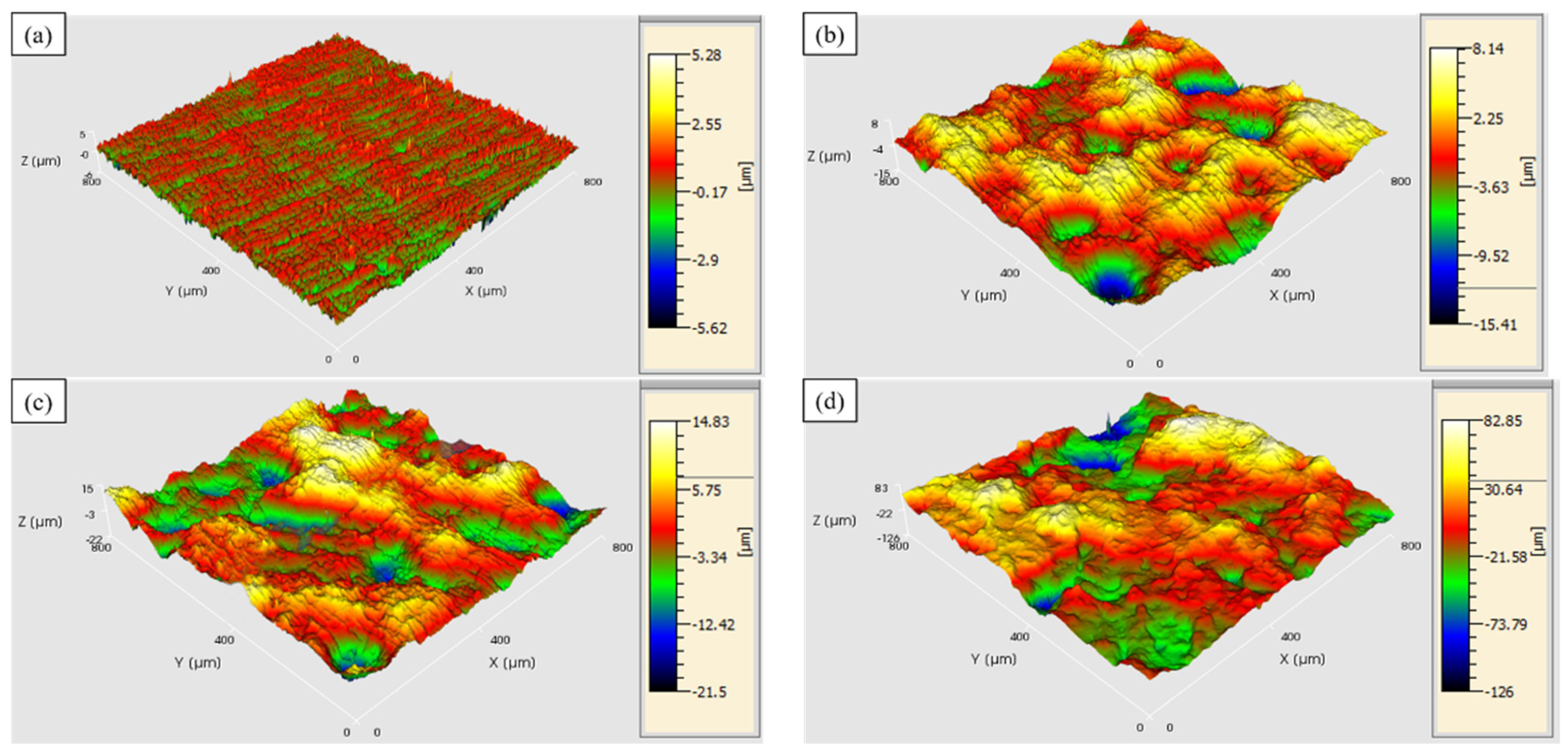
Figure 2 demonstrates the three-dimensional morphology of the surface of the Al7075 specimen at different scanning speeds, and
Table 2 shows the corresponding surface roughness values. We measured each sample three times, as well as obtained its average value and standard deviation.
Figure 2a shows the three-dimensional morphology of the surface of the specimen without impact passing, with a relatively flat surface and a roughness value of 0.46 μm.
Figure 2b shows the three-dimensional surface morphology of the peened specimen at a scanning speed of 1 mm/min. It is found that the roughness value is about 1.77 μm. The high-pressure impact generated by the micro-jets and shock waves due to the collapse of the cavitation bubble on the surface of the specimen creates some plastic deformation craters on the surface of the specimen with small diameters and shallow depths, indicating the small amount of plastic deformation of the surface layer of the specimen. Thus, the peening intensity is not high nor effective in this working condition.
Figure 2c shows the three-dimensional morphology of the surface of the peened specimen at a scanning speed of 0.5 mm/min. With the increase in the impact duration, the corresponding roughness value rises remarkably to around 4.18 μm. The distribution density of the resulting craters increases to a certain extent, and both the diameter and the depth become larger compared to the ones in the case of 1.0_CWJP. When the scanning speed reaches 0.1 mm/min, the surface plastic deformation produced by the CWJP on the Al7075 specimen increases significantly. Therefore, as shown in
Figure 2d, the roughness rises rapidly to 15.37 μm, implying the effectiveness of the CWJP on the Al7075.
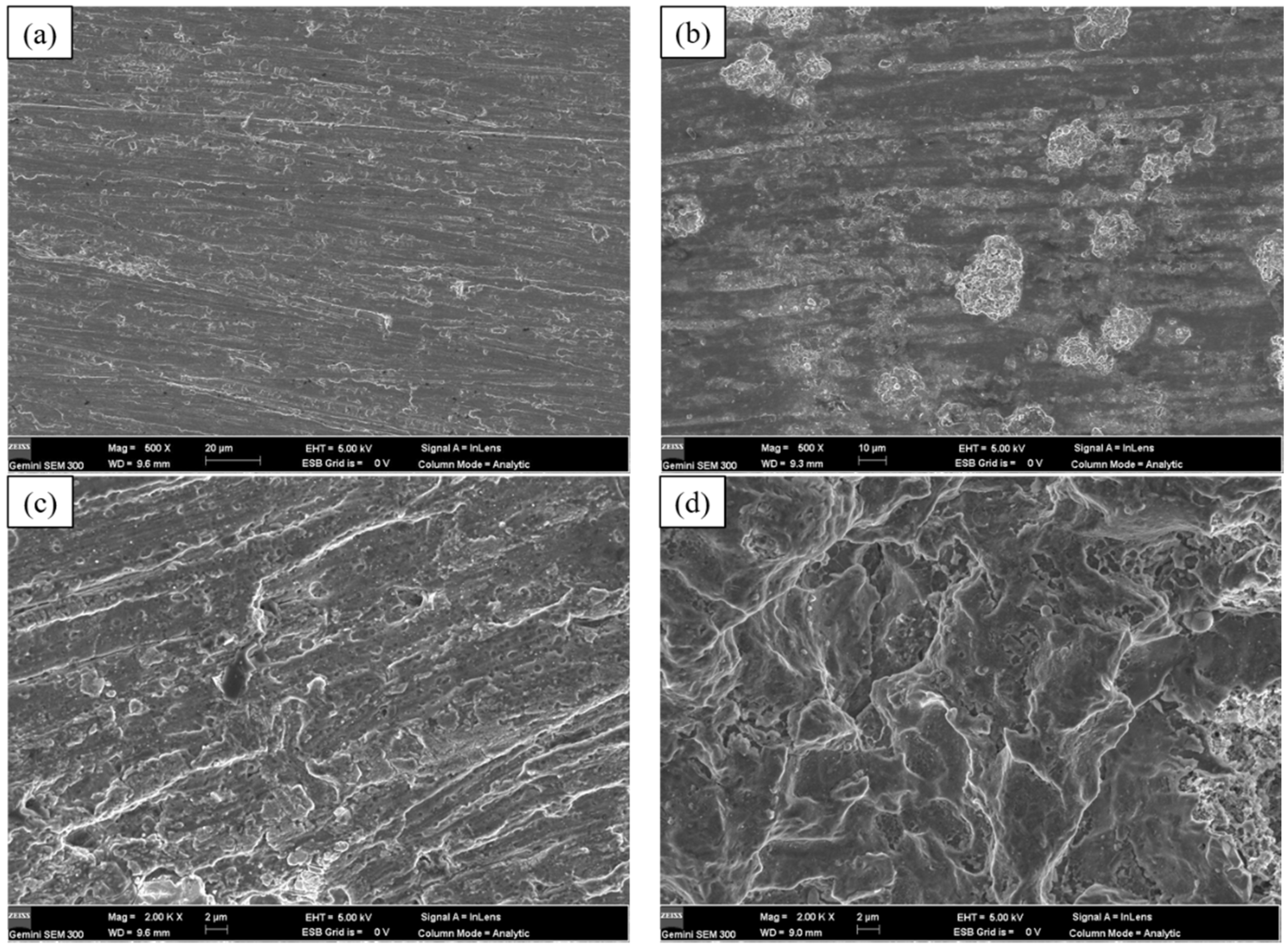
The extensive plastic deformation on the surface of the specimen is formed by the impact owing to the collapse of a large number of cavitation bubbles; thus, the accumulation of treatment time is a key factor in the formation of effective plastic deformation. The SEM images in
Figure 3 show the morphology of the sample surfaces at different scanning speeds.
Figure 3a shows the SEM morphology of the specimen without an impact, and the surface of the specimen is relatively smooth except for the scratches.
Figure 3b reveals the SEM morphology of the specimen at a scanning speed of 1 mm/min. Due to the fast scanning speed and the short action time, there are not enough cavitation bubbles to collapse; thus, the surface of the specimen cannot be deformed. Indeed, it can be observed that there are several pits on the surface of the sample, but the distribution density is not high.
As shown in
Figure 3c, the plastic deformation of the specimen increases as the scanning speed decreases to 0.5 mm/min. The impact craters show signs of edge buckling due to the pressure impact of the continuous collapse of the cavitation bubbles, and this extends to the periphery, showing a tendency for interconnection. From
Figure 3d, it can be observed that with the further reduction in the cavitation jet peening scanning speed to 0.1 mm/min, the plastic deformation of the specimen surface further increases, as well as the area of depression caused by the jet impact expands over a large area and the number of craters caused by the collapse of the vacuole increases substantially; thus, the phenomenon of concatenation and overlap of craters appears.
3.2. Microhardness and Residual Stress Analysis
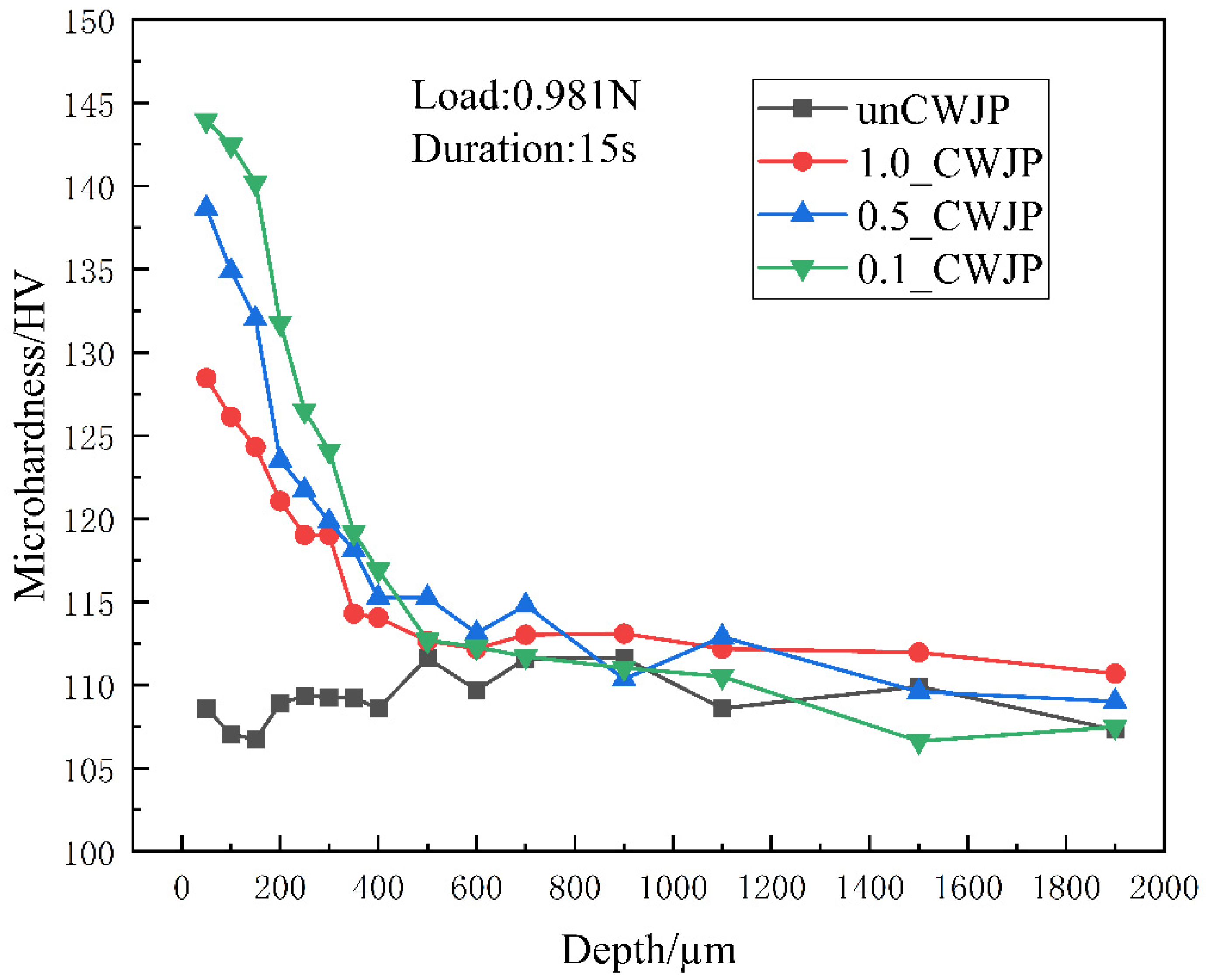
Figure 4 shows the magnitude of the microhardness values of the Al7075 at different depths before and after the CWJP treatment. The microhardness distribution of the unCWJP specimens in the depth direction is relatively stable, with an average value of 109.2 HV. After the CWJP treatment, grain refinement and dislocation strengthening occurred on the surface layer of the specimen, and the surface microhardness had the largest value. The CWJP scanning speed had a great influence on the surface microhardness of the specimen; the surface hardness value of the material tended to increase gradually as the scanning speed decreased, and the treatment time of the cavitation bubble became longer. When the CWJP scanning speed reached 1.0 mm/min, the highest microhardness of the specimen surface layer was 128.5 HV, and the microhardness of the specimen surface layer increased significantly compared with that of the unCWJP specimen. When the scanning speed of the CWJP was 0.5 mm/min, the maximum microhardness of the specimen surface layer was about 138.7 HV, and the increase in the specimen surface microhardness started to slow down. When the CWJP scanning speed was 0.1 mm/min, the maximum microhardness of the specimen surface layer was 144.0 HV, and the microhardness of the specimen surface layer increased more slowly. With the increase in the specimen depth, the microhardness gradually decreased until it stabilized at the same hardness value as the substrate, indicating that an effective hardened layer could be formed on the surface of the Al7075 after being reinforced by the CWJP; the CWJP scanning speed did not have much influence on the thickness of the hardened layer of the specimen, which was about 600 μm.
Due to the presence of a large number of cavitation bubbles in the cavitation water jet, their collapse will turn the surroundings into a high-temperature and high-pressure environment, resulting in plastic deformation of the material surface, distortion of the internal lattice of the material, changes in the grain surface spacing and the appearance of dislocations, which are the internal factors of residual stress generation.
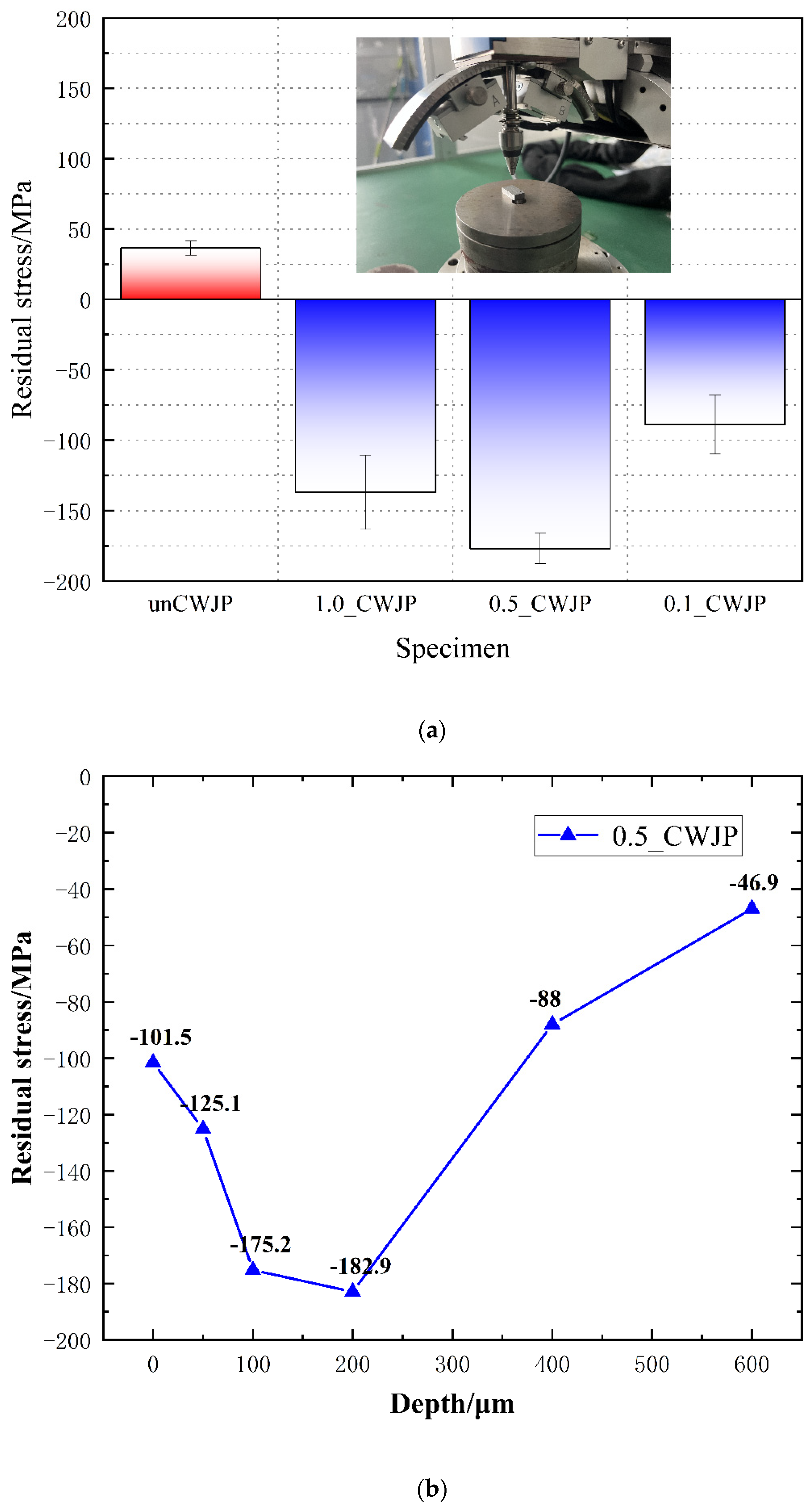
Figure 5a shows the residual stresses in the surface layer of the Al7075 before and after the CWJP treatment. A high-magnitude tensile residual stress of 36.5 MPa was generated in the subsurface layer of the unCWJP specimen. During a CWJP, a severe plastic deformation of the material surface caused by the cavitation jet shock wave can lead to strain-hardening effects and implant compressive stresses in the material. When the CWJP scanning speed was 1.0 mm/min, the peak residual compressive stress in the surface layer of the specimen reached −136.9 MPa. When the CWJP scanning speed was 0.5 mm/min, the peak residual compressive stress of the specimen surface reached −176.9 MPa, and the maximum residual compressive stress of the specimen surface was elevated more gently. Additionally, when the CWJP scanning speed was 0.1 mm/min, the residual compressive stress in the surface layer of the specimen dropped rapidly to −88.8 MPa. The intrinsic reason is that the repeated impact of the cavitation bubble collapse at high pressure for a long time reaches the fatigue limit of the material, so that the reinforced layer originally formed on the surface of the material is stripped away by cavitation, which greatly reduces the surface properties of the material. Therefore, the CWJP time needs to be strictly controlled, and cavitation spalling should be strongly avoided after achieving the goal of improving the surface properties of the material. Considering the strengthening effect and strengthening efficiency, 0.5 mm/min was determined as the optimal scanning speed.
Figure 5b shows the residual stress curve of the 0.5_CWJP specimen along the depth direction. The residual stress value from the surface of this specimen to a depth of 200 μm gradually became smaller along the depth; from 200 μm to 600 μm, the residual stress gradually became larger again. This indicates that the grain structure distribution is improved in a certain depth range after the CWJP surface treatment.
3.3. Microstructural Characterization Analysis
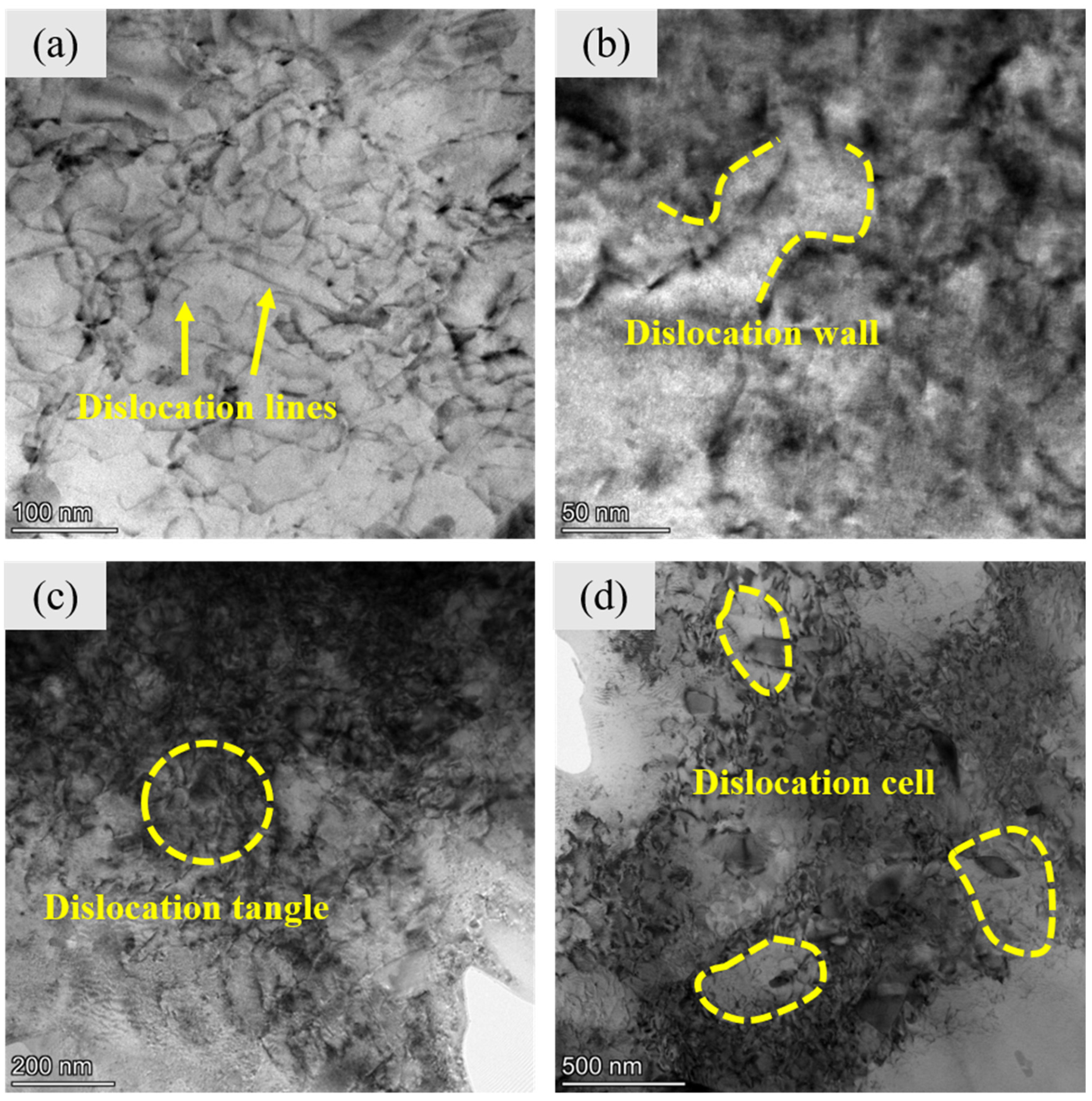
Figure 6 shows the TEM images of the microstructure at a 50-μm depth after the 0.5_CWJP. The results show that the main deformation mode is a dislocation slip. The plastic strain induces the production of high-density dislocation walls (
Figure 6b), dislocation entanglement (
Figure 6c) and dislocation cells (
Figure 6d). From
Figure 6a, it can be observed that only a few dislocation lines are randomly distributed in the substrate. When the material undergoes CWJP, a large number of dislocations appear, rearrange and annihilate to accommodate the plastic strain. As the strain increases, the stacked dislocation lines with the same sign pile up to produce dislocation walls and dislocation entanglement. The dislocation density is not uniform, and the dislocations within the grains are randomly distributed.
Figure 6c depicts the complex entanglement between the dislocations.
Figure 6d shows the full activation of the cross-slip, leading to high-density dislocation aggregation around the dislocation cell and sparse dislocation lines inside the dislocation cell.
Taheri-Nassaj et al. [
23] pointed out that the clustered high-density dislocation structures interacted with each other and impeded their own motions, thereby contributing to a microhardness increase in this region. The strengthening mechanism was Taylor strengthening. Liu et al. [
24] investigated the microstructural evolution of the FeCrNiCoMn alloy and believed that the average thickness of the mechanical twins (MTs) and their spacing played a significant role in the strengthening.
In the paper, on the other hand, mechanical twins cannot be observed in Al alloys even though they are under high strain rates due to the cavitation impact. The high stacking fault energy and dislocation slip of the Al7075 lead to the occurrence of dynamic recrystallization processes, and in the near-surface region, severe plastic strain refines the coarse grains to ultra-fined grains, which also contributes significantly to the corresponding maximum microhardness. Stepanov et al. [
25] proposed that substructure hardening should be taken into account due to the dislocation density. The overall hardness is associated with the microhardness of the substrate, the substructure hardening and the Hall–Petch hardening, indicating that dislocation and grain size are the critical factors.
The microhardness of the cavitation jet-strengthened Al7075 containing dislocation strengthening and grain refinement strengthening is described as follows:
From the equation, it can be observed that the higher the dislocation density, the greater the dislocation strengthening effect. From the TEM diagram, it can be observed that the material is deformed after the impact, and a large number of dislocations are entangled to form a high dislocation density. The dense high-density dislocation structures interact with each other and hinder their own motion; thus, promoting the increase in microhardness. The hardness of the material increases as the grain size decreases; therefore, grain refinement also plays an important role in the cavitation jet strengthening of the 7075 aluminum alloy.
3.4. Grain Refinement Mechanisms Induced by CWJP
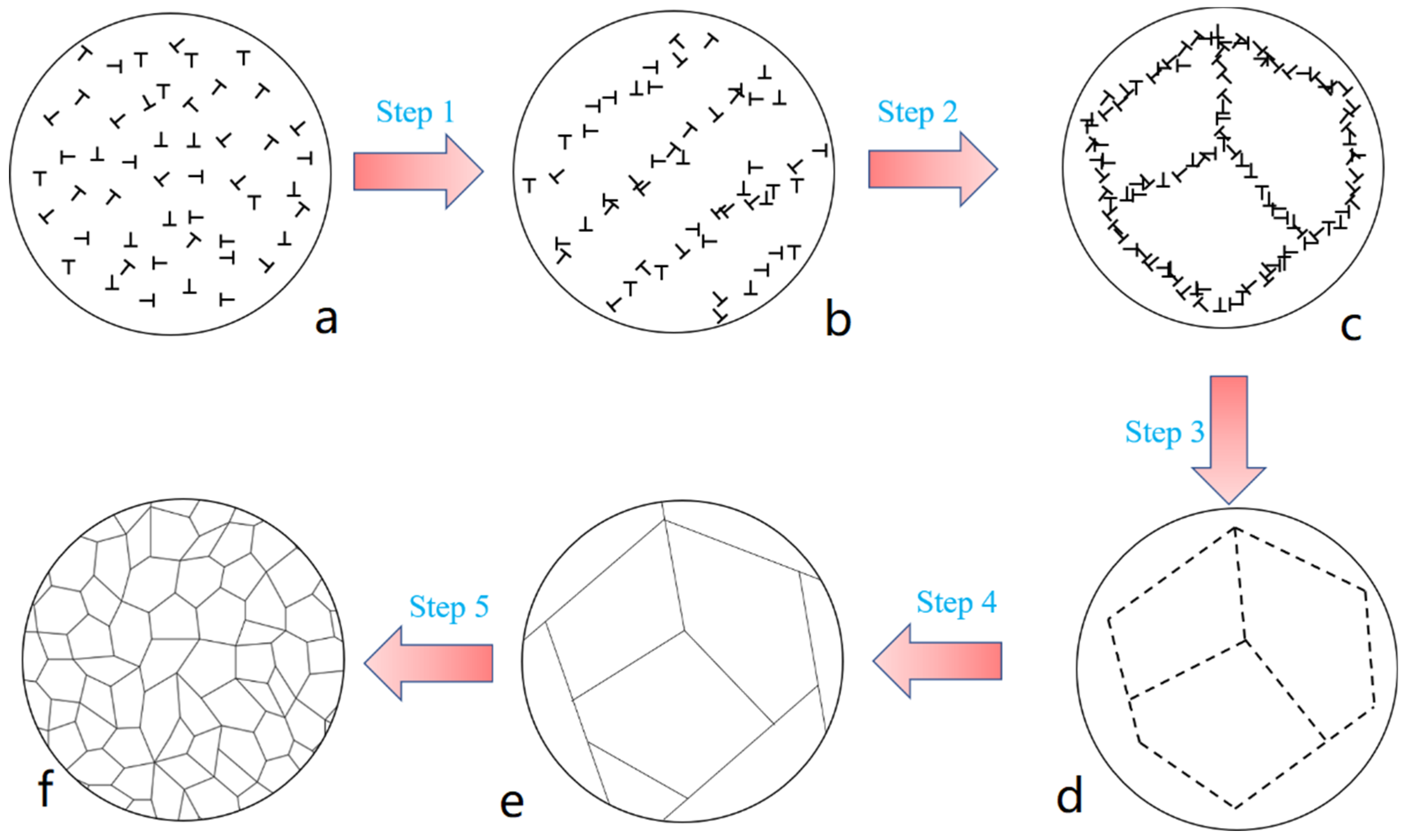
When the impact source acts on the specimen, a shock wave is formed on the surface of the material. The resultant propagation of the shock wave inside the material induces the intracrystalline dislocations to move. The grain refinement process of the Al7075 during the CWJP can be divided into five steps, which are described as follows, and the schematic diagram is illustrated in
Figure 7.
Step 1: The dislocation behavior leads to the formation of dislocation lines within the original coarse crystal.
Step 2: The accumulation of dislocation lines leads to the formation of dislocation walls and dislocation tangles.
Step 3: As the strain increases further, the individual dislocation cells, initially separated by the dislocation entanglement and dislocation walls, will gradually subdivide into the original subgrains.
Step 4: When the deformation strain reaches a certain level, that is, when the dislocation density of the dislocation walls and dislocation tangles reaches a certain value, the annihilation of the rearrangement of these dislocations forms low angular grain boundaries and subdivides the original coarse grains into different subgrains.
Step 5: The high-level stacking fault energy and the dislocation slip of the aluminum alloy lead to a continuous dynamic recrystallization process, which leads to a further increase in grain boundary misorientation. Finally, the grain boundary properties are changed gradually until the formation of high-angle grain boundaries.


