Article

Developing the Fast Ionic Transport in the Semiconductor Ionic Heterostructure Composed of La0.8Sr0.2Co0.8Fe0.2-Gd0.1Ce0.9O2 for the Electrolyte Application in Ceramic Fuel Cells

1
College of Electronic and Engineering, Nanjing Xiaozhuang University, Nanjing 210017, China
2
Secondary Specialized School of PuKou, Nanjing 211899, China
3
Jiangsu Provincial Key Laboratory of Solar Energy Science and Technology/Energy Storage Joint Research Centre, School of Energy and Environment, Southeast University, No. 2 Si Pai Lou, Nanjing 210096, China
*
Author to whom correspondence should be addressed.
Crystals 2023, 13(4), 697; https://doi.org/10.3390/cryst13040697
Submission received: 18 December 2022 / Revised: 3 April 2023 / Accepted: 11 April 2023 / Published: 19 April 2023

Abstract

:
The challenging research topic for developing low-temperature ceramic fuel cells (LT-CFCs) is to design electrolytes with sufficient ionic conductivity either via doping or composite semiconductors with ionic conductors. Following this challenging topic, we have developed and synthesized a novel semiconductor ionic heterostructure La0.8Sr0.2Co0.8Fe0.2O3-Gd0.1Ce0.9O2 (LSCF-GDC) with different compositions and deployed it as an electrolyte to realize the functionality of the fuel cell. The developed LSCF-GDC electrolyte with mixed conduction of ions and protons possesses high ionic conductivity with only 0.06 Ohm·cm2 of ohmic area-specific resistance for the electrolyte component. The fuel cell using 3LSCF-7GDC as the electrolyte exhibits the best fuel cell performance of 1060 mW·cm−2 and an open circuit voltage (OCV) of 1.11 V at a low operating temperature of 550 °C among individual GDC, LSCF, and different heterostructures of LSCF and GDC. The attained performance and ionic conductivity are specially accredited to constructing heterostructures and massively deficient structures at the interface of the LSCF and GDC. The advanced semiconductor ionic heterostructure of LSCF-GDC provides new insight into designing new electrolytes with high ionic conductivity for LT-CFC applications.

1. Introduction

The main driving force to attain long-term, stable, high-power output is enhanced ionic conduction in low-temperature ceramic fuel cells (LT-CFCs) [1,2,3,4]. Various fuel cells are generally designed to resume ionic conduction and insulate the electronic conduction through the electrolyte layer [5,6]. However, SOFCs (solid oxide fuel cells), which convert chemical energy into electrical energy, are a worthy candidate in terms of better efficiency, long-term stable operation, and many more benefits. In this regard, chemists design different types of ionic conductors, including yttria-stabilized zirconia (YSZ), composite it with samarium-doped-ceria (SDC), and function as an electrolyte layer to achieve adequate conduction of ions at different operational temperatures of 800–1000 °C for ceramic fuel cells [7]. However, the main issue is realizing fuel cell operation at low temperatures using YSZ as an electrolyte, as YSZ has failed to reduce the temperature for CFCs [8]. However, the high operating temperature of 800–1000 degrees raise multiple challenges, including quick start-up and shutdown of the cycles and rapid device degradation [9]. Thus, the primary and essential task is reducing the operating temperature to promote and market the SOFC device further. Therefore, advanced thin-film technologies and tape casting have been introduced to mitigate high operating temperature bottlenecks and attain high ionic conductivity for LT-CFCs. Controlling or reducing the thickness is crucial and feasible using these technologies to minimize the ohmic and polarization losses. However, the existing cost of scaling up thin film negatively affects the durability and performance of the stack-based device, hindering the commercialization of CFCs [10,11,12,13,14]. Generally, instability, material cost, and partial electronic conduction are CFC’s main challenges, which need to be addressed [6,8,15,16,17].
La0.2Sr0.8Co0.4Fe0.6O3−δ, a mixed ionic and electronic conductor (MIEC), has been identified as a desired cathode material for SOFCs operating below 800 °C due to its outstanding catalytic function for cathodic reactions and excessive electronic conductivity. If we can take advantage of the ionic conductivity and electrocatalytic function of LSCF, we may develop a new functional material and device by exploiting MIEC LSCF. To deal with the issues stated above with the electrolyte layer, a new concept of novel technology semiconductor ionic materials has been proposed and utilized, which seems to be an attractive and beneficial candidate to perform the fuel cell operation and deliver high ionic conductivity at a low operational temperature. Moreover, SIM-based electrolytes can deliver higher fuel cell performance with stable and higher open-circuit voltages without short-circuiting issues [18,19]. Typically, SIM is composed of perovskite oxide, and layered structure-based materials are used to realize the fuel cell operation. Various electrolytes have been designed to enhance ionic conduction to discover the functionality of SIM electrolytes at low temperatures of 400–600 °C. For example, Xia et al. proposed a new idea of a semiconductor heterostructure using p-BCFZY and n-ZnO to develop the p-n heterojunction (p-BCFZY, n-ZnO), used as an electrolyte in the following configuration: Ni-NCAL/BCFZY-ZnO/NCAL-Ni to realize the fuel cell operation. The sandwiched electrolyte layer between two symmetrical electrodes has delivered an efficient power output of 643 mW·cm−2 with a higher OCV of 1.01 V at a low operating temperature of 500 °C. Shah et al. have designed a new bilayer heterostructure (p-n SrCoSnO3-CeO2 heterojunction), applied it as an electrolyte, and delivered a maximum fuel cell performance of 672 mW·cm−2 along with a high ionic conductivity of 0.2 S/cm at 520 °C.
Moreover, another electrolyte-based technology based on the semiconductor ionic heterostructure was introduced and successfully used to operate fuel cells and achieve high ionic conductivity. Rauf et al. have proposed an advanced semiconductor ionic heterostructure using perovskite oxide BCFZY (Ba0.5Sr0.5Co0.1Fe0.7Zr0.1Y0.1O3−δ) and ionic conductor SCDC (Ca0.04Ce0.80Sm0.16O2−δ) and used as an electrolyte (BSCFZY-SCDC) to attain a high ionic conductivity of 0.22 S·cm−1 and impressive fuel cell performance of 900 mW·cm−2 at 550 °C. Similarly, many single-phase or heterostructure semiconductors have been proposed to achieve high ionic conduction with better efficiency at low temperatures. Additionally, in recent years, to investigate the exceptional electrolytes, the phenomena stated above and the proposed strategy have been repeatedly used for LT-SOFC.
Inspired by the literature stated above and characteristic of semiconductor ionic materials (SIM), we aim to present the hybrid heterostructure using LaSrCo0.8Fe0.2O3 semiconductor and GDC (Gd-doped CeO2) as an ionic conductor to shape the semiconductor ionic heterostructure. The LSCF was prepared using the sol-gel method, while the GDC was prepared using the co-precipitation method. The prepared electrolyte of different compositions of LSCF-GDC was prepared using the solid-blending technique and used as an electrolyte to study the electrical and electrochemical properties and compare with the reported literature. Moreover, different characterization techniques, including XRD (X-ray diffraction), SEM (scanning electron microscopy), TEM (transmission electron microscopy), XPS (X-ray photoelectron spectroscopy), and UV-Visible, can be used to evaluate the structural, morphological, surface, and energy bandgaps. The construction of heterostructures and energy band alignment lead to a maximum fuel cell performance of 1060 mW/cm2, a better OCV of 1.1 V, high ionic conductivity, a low 0.06 Ohm·cm2 of ohmic area-specific resistance, and a feasible approach to developing novel electrolytes for LT-CFCs.

2. Materials and Methods

2.1. Synthesis Procedures

Sol-gel auto-combustions were used to make the La0.8Sr0.2Co0.8Fe0.2O3 and Gd0.1Ce0.9O2 powers. To make LSCF granules, 99.98% pure La (NO3)2·6H2O, Sr (NO3)2·6H2O, Co(NO3)2·6H2O, and Fe(NO3)2·9H2O were purchased from Alfa Aesar (GmbH & Co KG, Alfa Aesar, Shanghai, China). Step one involved dissolving of 0.1 moles of EDTA in deionized water, then adding NH3 to bring the pH of the solution to 7.0 and clarify the solution. After that, the solution mentioned above was supplemented with La (NO3)2·6H2O, Sr(NO3)2·6H2O, Fe(NO3)2·9H2O, and Co(NO3)2·9H2O in adequate amounts. Subsequently, a brownish gel was produced from the initially brownish LSCF solution by stirring at 300 rpm at 85 °C for 8 h. The resulting LSCF brownish gel was then aged for a day at room temperature, then dried in an oven at 140 °C. The gel was desiccated, ground, and calcined at 1000 °C for 8 h in the open air. In addition, powders of Gd0.1Ce0.9O2 (GDC) were synthesized by the co-precipitation technique from Ce (NO3)2·9H2O and Gd (NO3)2·9H2O. A proper amount of these metal nitrates was added to deionized water. Then, a second solution of Na2CO3 was made and added drop by drop to the Ce and Gd (NO3)2·9H2O solution to act as a precipitating agent. The obtained precipitates were dried in an oven at 120 °C for four hours and then heated at 700 °C for 4 h for calcination. For comparison, we mixed the LSCF mentioned above and GDC granules in various mass ratios, including 1 LSCF-9SDC, 2 LSCF-8GDC, 3 LSCF-7GDC, 4 LSCF-6GDC, and 5 LSCF-5GDC, to prepare LSCF-GDC heterostructure.

2.2. Characterization Tools and Electrochemical Measurements

Using a Bruker D8 Professional X-ray Analyzer (Bruker Corporation, Billerica, MA, USA) with Cu Kα monochromatic light, = 1.5418 Å in 2 ranges from 10 to 90° was used for the structural crystallinity of prepared individual LSCF, GDC, and several LSCF-GDC heterostructures. LSCF-GDC heterostructure composite was analyzed for its microstructure, crystal structure, and chemical content using an FEI Tecnai GI F30 and a JEOL JSM7100F (Akishima, Tokyo), a high-resolution transmission electron microscope (HR-TEM), and a field emission scanning electron microscope (FE-SEM). The UV-Vis 3600 spectrophotometer (Thermo Fisher Scientific Inc., Waltham, MA, USA) was used to determine the UV-Vis absorption. We used 449F3 Thermal analyzer to measure thermogravimetric and differential scanning (TG/DSC, Linseis Messgeraete GmbH, Selb, Germany) at temperatures from 30 to 800 °C in air. Raman spectra were collected using a spectrophotometer manufactured by NT-MDT, Moscow, Russia, and excited by a solid-state laser emitting at 532 nm with 20 mW of laser power as the excitation source.

2.3. Fabrication of Fuel Cells

This work includes solid oxide fuel cell devices featuring a porous Ni0.8Co0.15Al0.05LiO2−δ (NCAL) electrode, dense GDC electrolyte, and various LSCF-GDC heterostructures fabricated using a straightforward dry pressing technique. Using a brush, we applied a slurry made from C10H18O and the layered NCAL powders we bought from Bamo Sci. & Tech. Joint Stock Company Ltd., Tianjin, China. Next, the NCAL-sprayed Ni-foam electrode was dried in a 120 °C for 2 h. Powdered GDC and different LSCF-GDC heterostructures were pressed between two NCAL/Ni-foam electrodes in a steel mold of 13 mm diameter (pressure, 240 MPa) to create a solid fuel cell device with a thickness of ≅1 mm and an active area of 0.64 cm2. The performance of the fuel cell in its as-fabricated condition was measured using an ITECH8511dc electronic load instrument (ITECH Electrical Co., Ltd., New Taipei, Taiwan) with H2 as the fuel and ambient air as the oxidant at flow rates of 100–110 mL/min and 100 mL/min, respectively. The electrochemical characteristics of the FC devices were demonstrated by providing the resulting I-V and I-P curves from the measured data. Using a Gamry Reference 3000, USA (Warminster, PA, USA) workstation, and a 10-mV dc signal at an open-circuit voltage, electrochemical impedance spectroscopy (EIS) measurements were made from 0.1 Hz to 106 Hz (OCV). ZSIMPWIN software was used to analyze the collected data and produce EIS outcomes.

3. Results

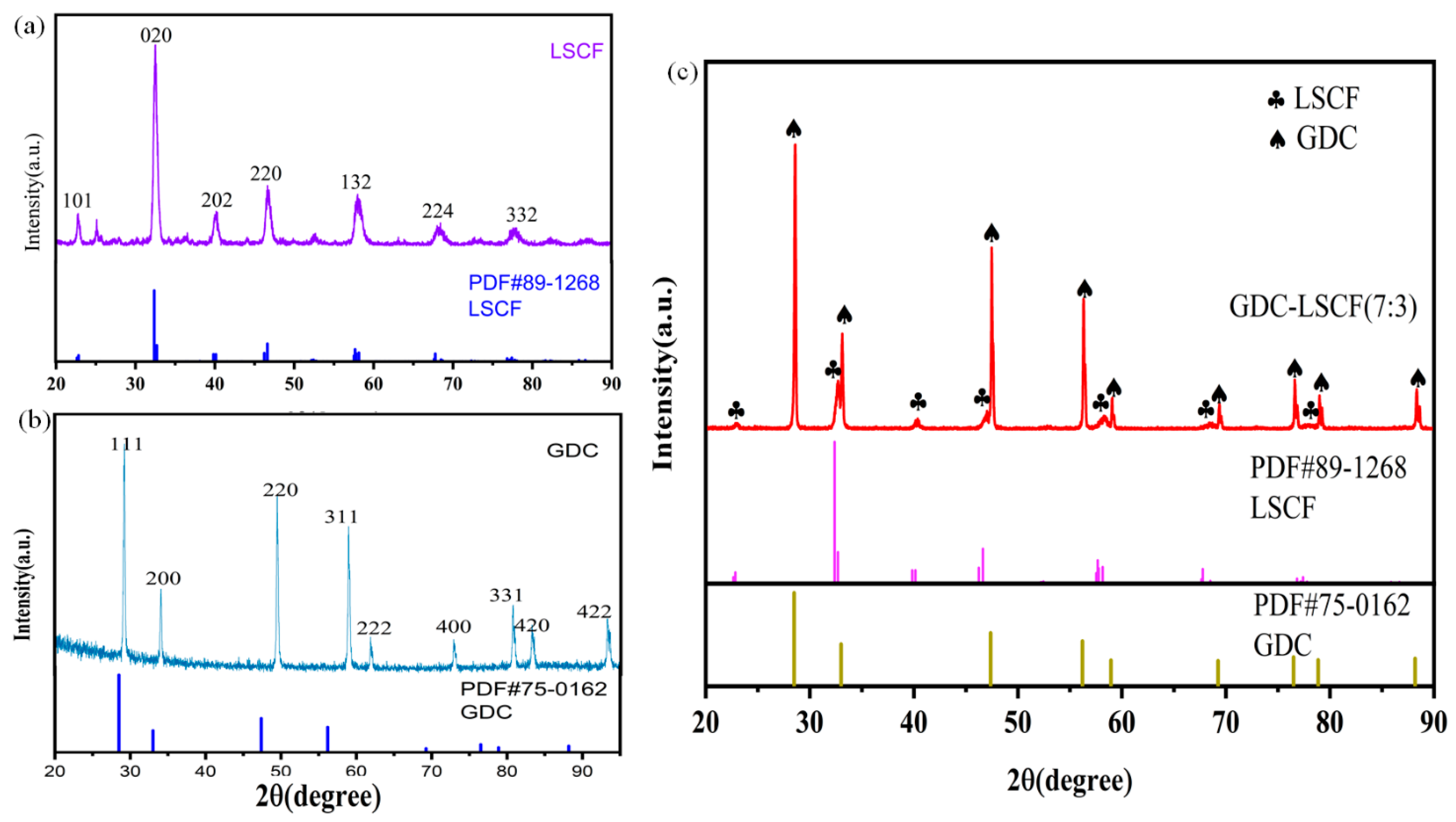
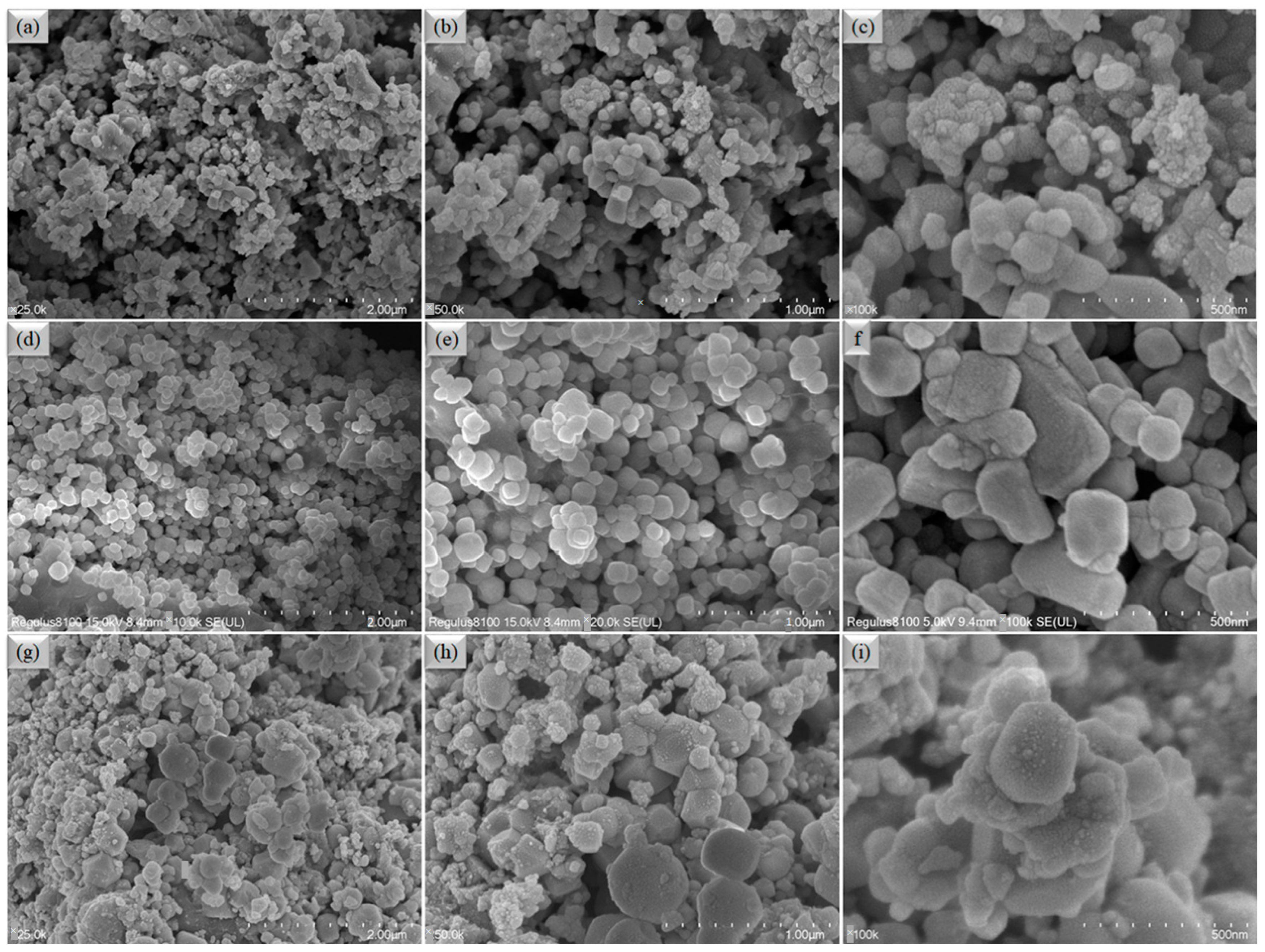
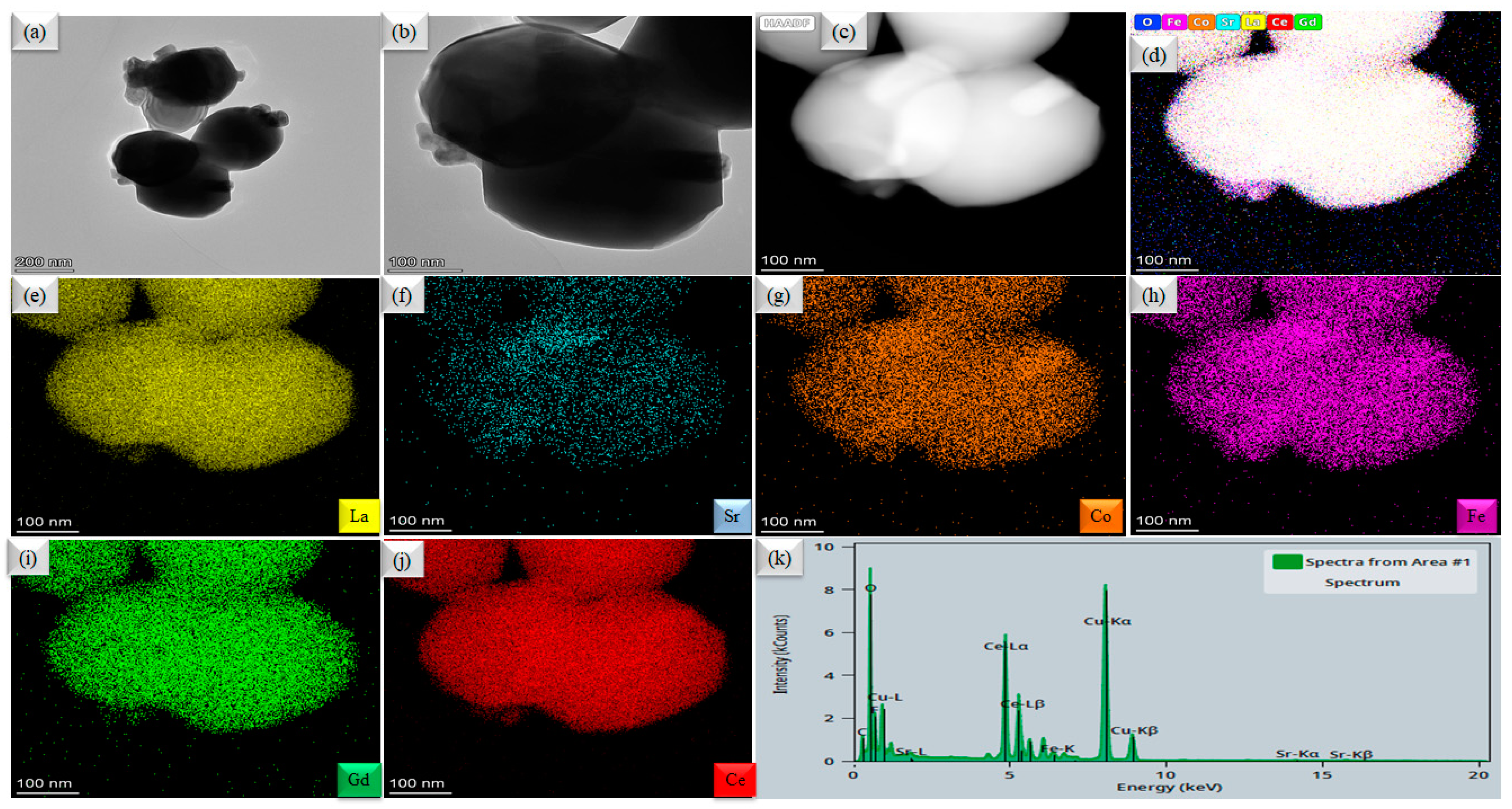
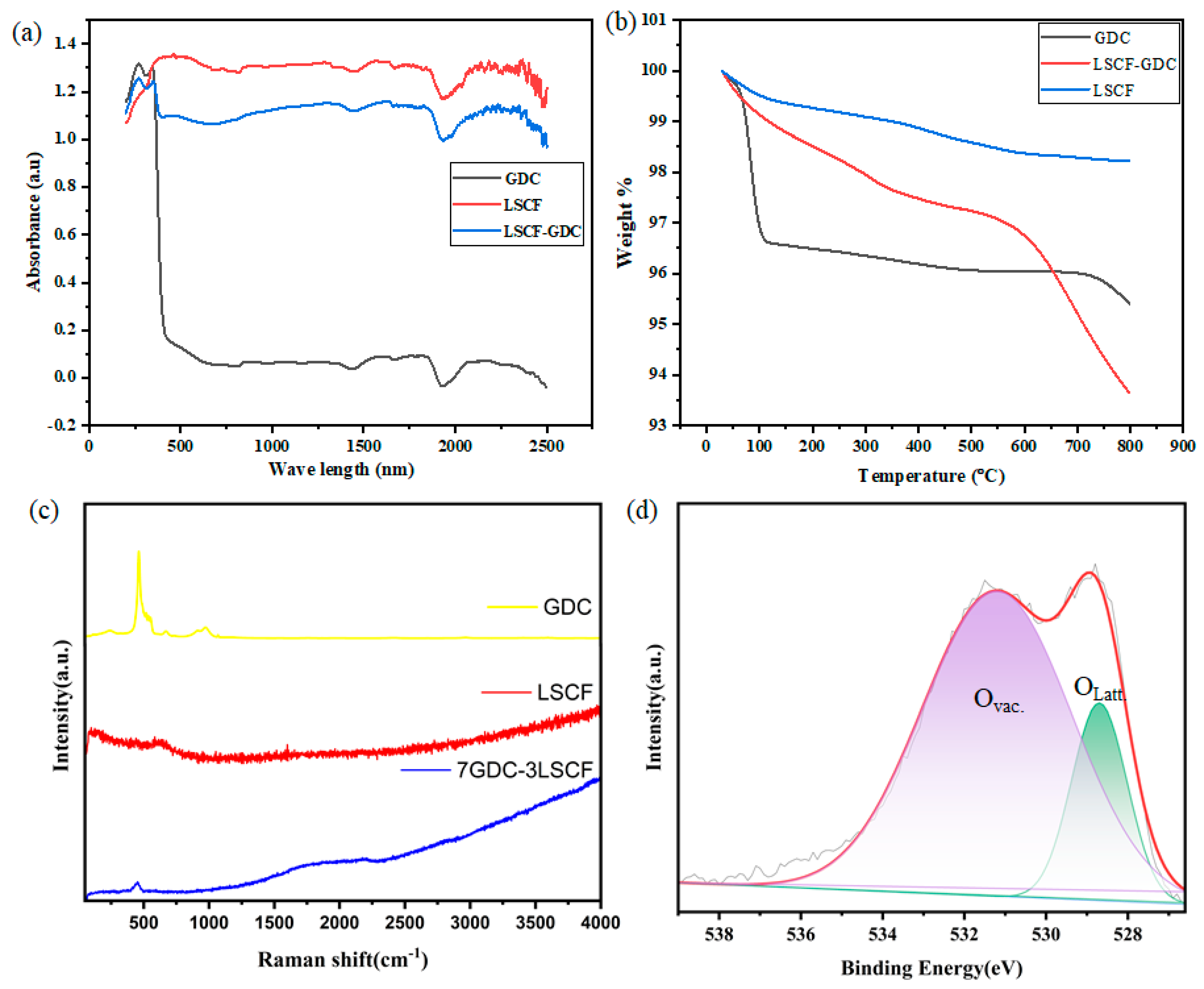
3.1. Structure and Composition Analysis

X-ray diffraction (XRD) patterns of La0.8Sr0.2Co0.8Fe0.2O3−δ (LSCF) and Gd-doped CeO2 are shown in Figure 1a,b, respectively (GDC). Figure 1c displays the XRD pattern of a heterostructure combination of LSCF and GDC in the 2θ range of 20–90 degrees. As can be seen in Figure 1a, corresponds to the (101), (020), (220), (132), (224), and (332) planes of LSCF (JCPDF # 89-1268), with the dominant diffraction peaks found at 24, 32, 1, 38, 8, 45, 6, 68, 75, and 76. According to Figure 1b, the XRD diffraction pattern of GDC was observed at 28.5°, 33.08°, 47.47°, 56.3°, 69.4°, 76.7°, and 79.07°, corresponding to the (111), (200), (220), (311), (222), (400), (331), and (420) planes, respectively (JCPDF # 75-0162) [19,20,21,22,23]. While the cohabitation of two distinct diffraction patterns in the LSCF-GDC heterostructure composite demonstrates the presence of a mixed phase of perovskite-oxide (LSCF) and fluorite structure (GDC). As shown in Figure 1c, the LSCF-GDC heterostructure composite sample exhibited only the LSCF and GDC peaks in its diffraction patterns, ruling out the chance of a chemical reaction forming new phases.
In addition, the scanning electron micrographs (SEM) of individual LSCF, GDC, and LSCF-GDC bulk heterostructure combinations are depicted in Figure 2. The SEM image morphology of an individual LSCF is illustrated in Figure 2a,c. In this figure, a nanostructured, spherical-shaped particle can be seen in the middle of the picture. Although the SEM picture for the individual GDC particles is displayed in Figure 2d–f, where spherical particles could be corelated with GDC structure. In addition, the SEM images of the LSCF-GDC bulk heterostructure composite are shown in Figure 2g–i. These images have a mixed morphology of LSCF and GDC, and it is possible to see fragments of both LSCF and GDC.
High-resolution transmission electron microscopy (HR-TEM) and energy-dispersive spectroscopy (EDS) mapping of the LSCF-GDC bulk heterostructure is displayed in Figure 3. Figure 3a,b shows the HR-TEM image of LSCF-GDC particles where grain-level interaction between LSCF and GDC can clearly be observed. While Figure 3c shows the HAADF-STEM imaging of the 3LSCF-7GDC used for energy dispersive mapping. Figure 3d verifies the elemental distribution at the particle level of LSCF and GDC. The rudimentary mappings of each element of the LSCF-GDC bulk heterostructure present in Figure 3c are presented in Figure 3e–j which demonstrates that creating a heterostructure composite at the particle/grain level is confirmed by the homogeneous chemical spreading of each element, including La, Sr, Co, Fe, Gd, and Ce. The EDS spectrum of LSCF-GDC is also displayed in Figure 3k.

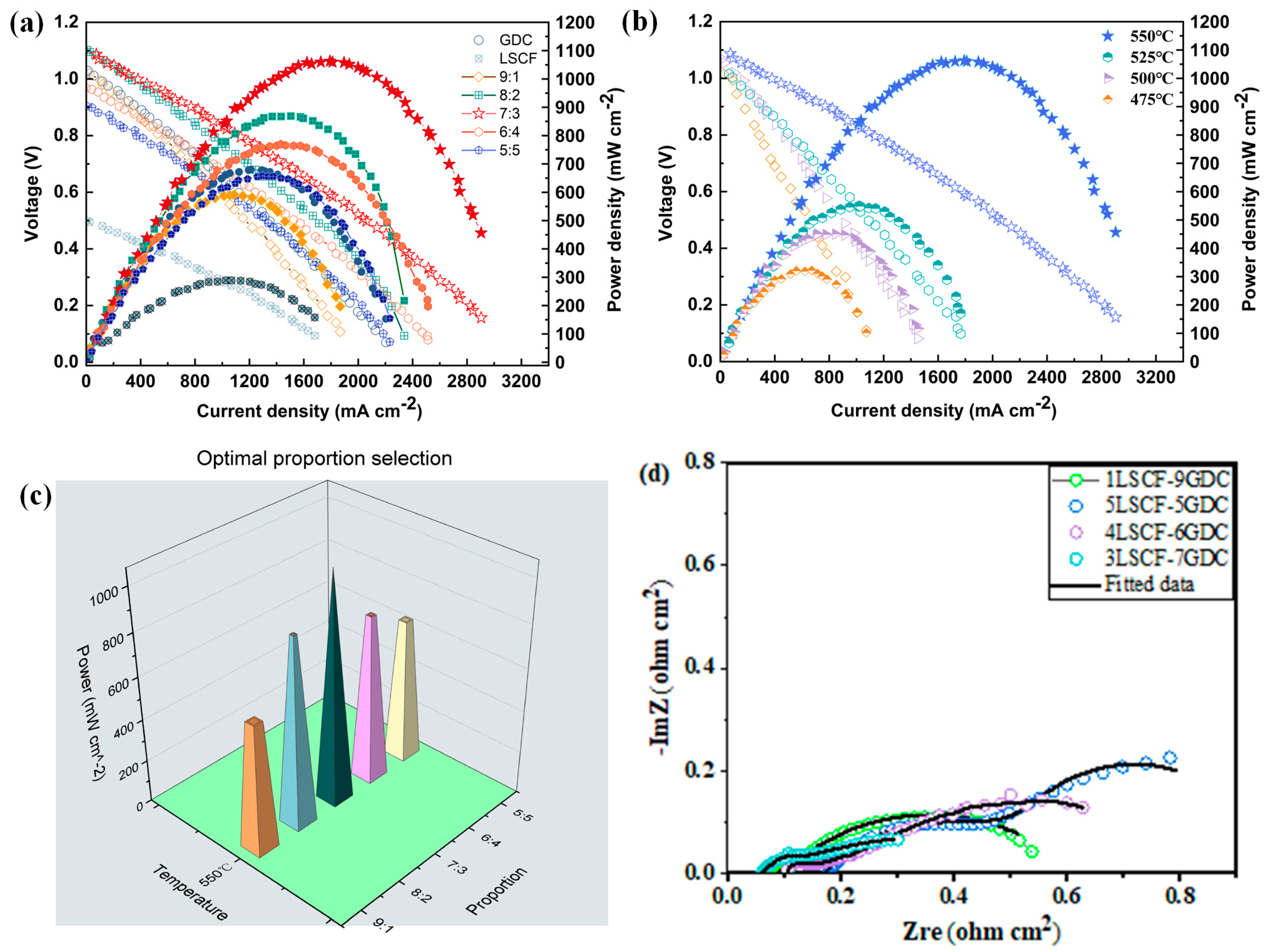
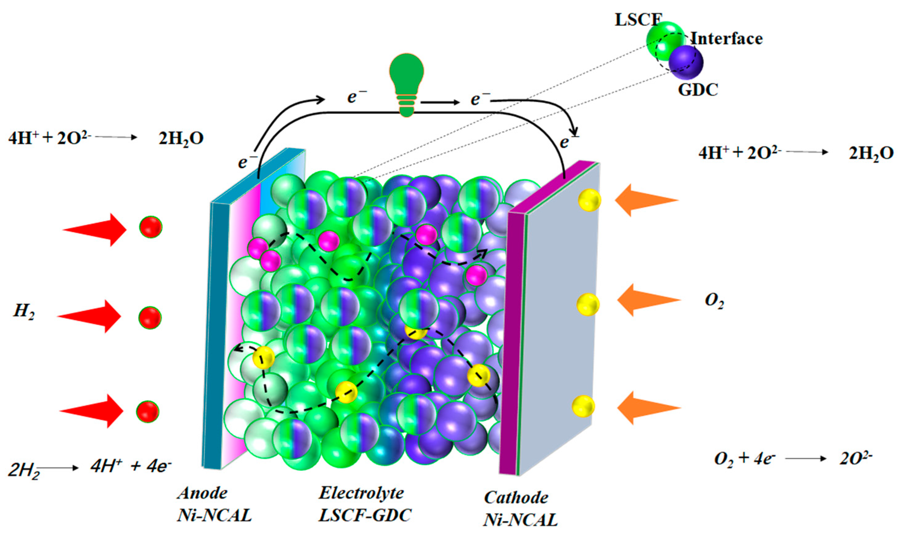
3.2. Electrochemical Performance Measurements

Measurements of the electrochemical performance of various heterostructure composites of LSCF and GDC were performed to evaluate the power output of the LSCF-GDC heterostructure we produced for fuel cells. Fuel cells using pure GDC, LSCF, and various heterostructure composites made of LSCF and GDC, all working at 550 °C, are depicted in Figure 4a, along with their typical current-voltage (I-V) and associated power-density (I-P) characteristics. With an OCV of 1.11 V and a maximal power density (Pmax) of 1060 mW cm−2, the 3LSCF-7GDC electrolyte outperformed both GDC (625 mW cm−2) and LSCF (230 mW cm−2) [23,24,25]. At low temperatures up to 475 °C, the 3LSCF-7GDC electrolyte fuel cell we built also showed excellent electrochemical power density (Figure 4b). At 525 °C, its power density peaked at 510 mW cm−2, while at 475 °C, it peaked at 305 mW cm−2. The electrochemical behavior of the various heterostructure composites is also compared in Figure 4c. The importance of the mass ratio of LSCF and GDC that creates a high oxygen-deficient structure for establishing the path for oxygen ions or protons transport is highlighted by the enhanced electrochemical performance of synthesized 3LSCF-7GDC electrolyte-based fuel cells over pure LSCF, GDC, and other LSCF-GDC heterostructures and composites [20,22].

3.3. Electrochemical Impedance (EIS) Analysis

In addition, at 550 °C in an H2/air fuel cell atmosphere, EIS characterizations of the cell with varying LSCF/GDC-based electrolyte mass ratios were performed under OCV circumstances. The Nyquist curve for the observed EIS is shown in Figure 4d. To simulate the EIS data of the fuel cell of the LSCF-GDC heterostructure electrolyte, the ZSIMPWIN software was used to model the equivalent circuit for R0-(R1-CPE1)-(R2-CPE2), where R0 represents the ohmic resistance from the electrolyte and R1, R2 represent the charge transfer and mass transfer losses from the electrode, respectively. The EIS spectra show that the 3LSCF-7GDC fuel cell has a much-reduced R0 (ohmic resistance) in H2/air (fuel cell operating conditions) at high temperatures compared to other compositions. In H2/air at 550 °C, the R0 of the 3LSCF-7GDC electrochemical fuel cell was only 0.06 cm2, while the R1 of the 3LSCF-7GDC was over 0.083 cm2. To reduce ohmic and polarization losses as well as the accumulation layer at the electrode-electrolyte contact, the 3LSCF-7GDC electrolyte shows the best opportunity. As seen from the EIS data in Figure 4d, this reduces the fuel cell’s mass transit resistance (R1) and its charge transfer resistance (R2). At each cell’s electrode/electrolyte interface, the capacitance value may drop as mass and charge transfer values decrease, (i.e., R1∼C1, R2∼C2). Capacitance values are obtained using the following equation: C i = ( R i Q i ) 1 / n R i , where R manifests the resistance and n to the frequency power [0 ≥ n ≤ 1] of the Q’s values [11,24,25,26,27].

3.4. Spectroscopic Analysis

UV-Visible, TGA, Raman, and X-ray photoelectron spectroscopy were used to investigate additional structural characteristics of LSCF, GDC, and LSCF-GDC powders. Figure 5a shows the UV-Visible absorbance spectra for unadulterated GDC, LSCF, and LSCF-GDC. It can be demonstrated that the as-synthesized LSCF, GDC, and LSCF-GDC powders all have very different absorbance bands. Absorbance spectra variations show that manufacturing the heterostructure composite reduces the energy band gap of LSCF-GDC due to the introduction of oxygen vacancies. This is seen in many cases [21,24,25,28] where oxygen holes are introduced and the energy band gaps of the metal oxides are lowered. Figure 5b displays the results of a TGA performed in air at temperatures ranging from 25 to 800 °C on pure LSCF, GDC, and LSCF-GDC to investigate the effects of temperature on heterostructure development. At temperatures close to 100 °C, evaporation of the absorbed water causes a fast mass loss in all three samples. For the GDC and LSCF-GDC powders, the other rapid weight changes begin at approximately 300 °C, while at 500–600 °C, oxygen vacancies are released from the lattice. The LSCF-GDC sample demonstrates the most significant mass shift, supporting our predictions. The considerable mass change in LSCF-GDC could be readily released due to the relaxation of the O bands during heterostructure formation.
The Raman spectrum comparison of LSCF, GDC, and LSCF-GDC is shown in Figure 5c. Raman bands for LSCF are at 710 cm−1, and GDCs are at 463 cm−1. However, a downshift in bands was seen in the LSCF-GDC heterostructure sample. The energy required to excite the vibrations along progressively looser bonds may be lower when both phases are present, which may account for the observed change in the Raman peak. High densities of active surface-oxygen species to boost ORR electrocatalytic activity are consistent with the LSCF-GDC forming due to labile oxygen bonding at the interface of the LSCF and GDC. The O1s XPS spectrum of the substance also shows the ionic conductivity of the developed material [29,30]. Due to a lopsided peak, different oxygen species levels can be seen in the LSCF-O1s GDC’s XPS spectrum. As shown in Figure 5d, the curve was fit to two different peaks (1 and 2), where lattice O2 ions bound to GDC and LSCF may account for the 528.2 eV peak, while the 530.1 eV peak may be ascribed to oxygen defects/vacancies, lending credence to the idea that more nonstoichiometric forms are being formed. An increased area percentage ratio of Olat/Ovac in the LSCF-GDC [21,28] indicates an increase in oxygen vacancies, which are essential for high fuel cell performance. Accordingly, our developed LSCF-GDC may represent a novel strategy for creating high-performance LT-SOFC electrolyte materials [31]. It shows that there are more oxygen vacancies in the LSCF-GDC than in the individual LSCF and GDC. To facilitate the movement of oxygen and proton ions, a defective LSCF-GDC layer is configured, as shown in Figure 6 [32].

4. Conclusions

In summary, a semiconductor heterostructure electrolyte based on perovskite-structured LSCF and its heterostructure composite with fluorite-structured Gd-doped CeO2 material are effectively assembled and characterized. The LSCF-GDCs that were made are also used as electrolytes in ceramic fuel cells. With a small area-ohmic specific resistance, the LSCF-GDC showed excellent fuel cell performance at 550 °C, producing over 1000 mW·cm2. LSCF-GDC electrolyte-based fuel cells have the potential to demonstrate very high ionic conductivity and fuel cell performance, as evidenced by the ohmic ASR of only 0.05 Ohm·cm2. The fuel cell operating at 550 °C and using various heterostructure materials for the electrolyte also showed promising electrochemical performance. In addition, we have used microscopic and spectroscopic analyses to determine the reason for the improvement in ionic conductivity of LSCF-GDC in comparison to pure LSCF, GDC, and various heterostructure composites. To achieve low ohmic area-specific resistance and create a high oxygen-deficient structure that facilitates O2− transport, we found that the ionic conductivity varies with the mass ratio of LSCF to GDC. In conclusion, this method can potentially motivate the development of new oxygen ion-conducting materials based on such heterostructures.

Author Contributions

Conceptualization, D.Z.; methodology, N.M. and P.W.; formal analysis and investigation, Y.L., R.Y., J.W. and H.L.; resources and data curation facilities, M.A.K.Y.S.; writing—original draft preparation, D.Z.; writing—review and editing, N.M., M.A.K.Y.S. and Y.L. All authors have read and agreed to the published version of the manuscript.

Funding

School of Electronic Engineering, Nanjing Xiaozhuang University, 211171 Nanjing, China, for providing experimental facilities. Further, this work was supported by the National Natural Science Foundation of China (NSFC) under grants #51772080 and 11604088 and Southeast University (SEU PROJET # 3203002003A2).

Data Availability Statement

The data supporting this study’s findings are available from the corresponding authors upon reasonable request.

Acknowledgments

The authors thank the School of Electronic Engineering, Nanjing Xiaozhuang University, Nanjing 211171, China.

Conflicts of Interest

The authors declare no conflict of interest.

References

  1. Duan, C.; Kee, R.J.; Zhu, H.; Karakaya, C.; Chen, Y.; Ricote, S.; Jarry, A.; Crumlin, E.J.; Hook, D.; Braun, R.; et al. Highly durable, coking and sulfur tolerant, fuel-flexible protonic ceramic fuel cells. Nature 2018, 557, 217–222. [Google Scholar] [CrossRef] [PubMed]
  2. Choi, S.; Kucharczyk, C.J.; Liang, Y.; Zhang, X.; Takeuchi, I.; Ji, H.-I.; Haile, S.M. Exceptional power density and stability at intermediate temperatures in protonic ceramic fuel cells. Nat. Energy 2018, 3, 202–210. [Google Scholar] [CrossRef]
  3. Malavasi, L.; Fisher, C.A.J.; Islam, M.S. Oxide-ion and proton conducting electrolyte materials for clean energy applications: Structural and mechanistic features. Chem. Soc. Rev. 2010, 39, 4370–4387. [Google Scholar] [CrossRef] [PubMed]
  4. Goodenough, J.B. Oxide-Ion Conductors by Design. Nature 1999, 404, 821–823. [Google Scholar] [CrossRef] [PubMed]
  5. Mastour, N.; Ramachandran, K.; Ridene, S.; Daoudi, K.; Gaidi, M. Tailoring the optical band gap of In–Sn–Zn–O (ITZO) nanostructures with co-doping process on ZnO crystal system: An experimental and theoretical validation. Eur. Phys. J. Plus 2022, 137, 1137. [Google Scholar] [CrossRef]
  6. Bi, L.; Da’As, E.H.; Shafi, S.P. Proton-conducting solid oxide fuel cell (SOFC) with Y-doped BaZrO3 electrolyte. Electrochem. Commun. 2017, 80, 20–23. [Google Scholar] [CrossRef]
  7. Hakim, M.; Yoo, C.-Y.; Joo, J.H.; Yu, J.H. Enhanced durability of a proton conducting oxide fuel cell with a purified yttrium-doped barium zirconate-cerate electrolyte. J. Power Sources 2015, 278, 320–324. [Google Scholar] [CrossRef]
  8. Muccillo, R.; Muccillo, E.N. Synthesis and Properties of BaZr0.1Ce0.7Y02−xMxO3−δ (x = 0, 0.1; M = Dy, Yb) Compounds. ECS Trans. 2011, 35, 1251. [Google Scholar] [CrossRef]
  9. Liu, Z.; Zhou, M.; Chen, M.; Cao, D.; Shao, J.; Liu, M.; Liu, J. A high-performance intermediate-to-low temperature protonic ceramic fuel cell with in-situ exsolved nickel nanoparticles in the anode. Ceram. Int. 2020, 46, 19952–19959. [Google Scholar] [CrossRef]
  10. Shah, M.Y.; Mushtaq, N.; Rauf, S.; Akbar, N.; Xing, Y.; Wu, Y.; Wang, B.; Zhu, B. Advanced fuel cell based on semiconductor perovskite La–BaZrYO3−δ as an electrolyte material operating at low temperature 550 °C. Int. J. Hydrog. Energy 2020, 45, 27501–27509. [Google Scholar] [CrossRef]
  11. Shah, M.A.K.Y.; Rauf, S.; Mushtaq, N.; Zhu, B.; Tayyab, Z.; Yousaf, M.; Hanif, M.B.; Lund, P.D.; Lu, Y.; Asghar, M.I. Novel Perovskite Semiconductor Based on Co/Fe-Codoped LBZY (La0.5Ba0.5Co0.2Fe0.2Zr0.3Y0.3O3−δ) as an Electrolyte in Ceramic Fuel Cells. ACS Appl. Energy Mater. 2021, 4, 5798–5808. [Google Scholar] [CrossRef]
  12. Lu, Y.; Mi, Y.; Li, J.; Qi, F.; Yan, S.; Dong, W. Recent Progress in Semiconductor-Ionic Conductor Nanomaterial as a Membrane for Low-Temperature Solid Oxide Fuel Cells. Nanomaterials 2021, 11, 2290. [Google Scholar] [CrossRef] [PubMed]
  13. Xia, C.; Mi, Y.; Wang, B.; Lin, B.; Chen, G.; Zhu, B. Shaping triple-conducting semiconductor BaCo0.4Fe0.4Zr0.1Y0.1O3−δ into an electrolyte for low-temperature solid oxide fuel cells. Nat. Commun. 2019, 10, 1707. [Google Scholar] [CrossRef] [PubMed]
  14. Shah, M.A.K.Y.; Mushtaq, N.; Rauf, S.; Xia, C.; Zhu, B. The semiconductor SrFe0.2Ti0.8O3−δ-ZnO heterostructure electrolyte fuel cells. Int. J. Hydrog. Energy 2019, 44, 30319–30327. [Google Scholar] [CrossRef]
  15. Xia, C.; Qiao, Z.; Shen, L.; Liu, X.; Cai, Y.; Xu, Y.; Qiao, J.; Wang, H. Semiconductor electrolyte for low-operating-temperature solid oxide fuel cell: Li-doped ZnO. Int. J. Hydrog. Energy 2018, 43, 12825–12834. [Google Scholar] [CrossRef]
  16. Xia, C.; Qiao, Z.; Feng, C.; Kim, J.-S.; Wang, B.; Zhu, B. Study on Zinc Oxide-Based Electrolytes in Low-Temperature Solid Oxide Fuel Cells. Materials 2018, 11, 40. [Google Scholar] [CrossRef]
  17. Stevens, J.; Wieczorek, W.; Raducha, D.; Jeffrey, K. Proton conducting gel/H3PO4 electrolytes. Solid State Ion. 1997, 97, 347–358. [Google Scholar] [CrossRef]
  18. Yashima, M.; Tsujiguchi, T.; Sakuda, Y.; Yasui, Y.; Zhou, Y.; Fujii, K.; Torii, S.; Kamiyama, T.; Skinner, S.J. High Oxide-Ion Conductivity through the Interstitial Oxygen Site in Ba7Nb4MoO20-Based Hexagonal Perovskite Related Oxides. Nat. Commun. 2021, 12, 556. [Google Scholar] [CrossRef]
  19. Wang, B.B.; Zhong, X.X.; He, C.L.; Zhang, B.; Cvelbar, U.; Ostrikov, K. Solvent-dependent structures and photoluminescence of WO3−x nanomaterials grown in nonaqueous solutions. J. Alloys Compd. 2021, 854, 157249. [Google Scholar] [CrossRef]
  20. Wang, Z.; Fan, X.; Li, C.; Men, G.; Han, D.; Gu, F. Humidity-sensing performance of 3DOM WO3 with controllable structural modification. ACS Appl. Mater. Interfaces 2018, 10, 3776–3783. [Google Scholar] [CrossRef]
  21. Shah, M.Y.; Rauf, S.; Zhu, B.; Mushtaq, N.; Yousaf, M.; Lund, P.D.; Xia, C.; Asghar, M.I. Semiconductor Nb-Doped SrTiO3−δ Perovskite Electrolyte for a Ceramic Fuel Cell. ACS Appl. Energy Mater. 2021, 4, 365–375. [Google Scholar] [CrossRef]
  22. Mushtaq, N.; Xia, C.; Dong, W.; Wang, B.; Raza, R.; Ali, A.; Afzal, M.; Zhu, B. Tuning the energy band structure at interfaces of the SrFe0.75Ti0.25O3−δ–Sm0.25Ce0.75O2−δ heterostructure for fast ionic transport. ACS Appl. Mater. Interfaces 2019, 11, 38737–38745. [Google Scholar] [CrossRef] [PubMed]
  23. Wang, B.; Cai, Y.; Xia, C.; Kim, J.S.; Liu, Y.; Dong, W.; Wang, H.; Afzal, M.; Li, J.; Raza, R.; et al. Semiconductor-ionic membrane of LaSrCoFe-oxide-doped ceria solid oxide fuel cells. Electrochim. Acta 2017, 248, 496–504. [Google Scholar] [CrossRef]
  24. Shah, M.A.K.Y.; Zhu, B.; Rauf, S.; Mushtaq, N.; Yousaf, M.; Ali, N.; Tayyab, Z.; Akbar, N.; Yang, C.P.; Wang, B. Electrochemical properties of a co-doped SrSnO3−δ-based semiconductor as an electrolyte for solid oxide fuel cells. ACS Appl. Energy Mater. 2020, 3, 6323–6333. [Google Scholar] [CrossRef]
  25. Mushtaq, N.; Lu, Y.; Xia, C.; Dong, W.; Wang, B.; Shah, M.Y.; Rauf, S.; Akbar, M.; Hu, E.; Raza, R.; et al. Promoted electrocatalytic activity and ionic transport simultaneously in dual functional Ba0.5Sr0.5Fe0.8Sb0.2O3−δ-Sm0.2Ce0.8O2−δ heterostructure. Appl. Catal. B Environ. 2021, 298, 120503. [Google Scholar] [CrossRef]
  26. Li, J.; Mushtaq, N.; Yousaf Shah, M.A.K.; Lu, Y.; Yan, S. Supercilious Enhancement in Oxygen-Reduction Catalytic Functionalities of Cubic Perovskite Structured LaFeO3 by Co-Doping of Gd and Ce for LT-SOFCs. Crystals 2023, 13, 242. [Google Scholar] [CrossRef]
  27. Shah, M.Y.; Tayyab, Z.; Rauf, S.; Yousaf, M.; Mushtaq, N.; Imran, M.A.; Lund, P.D.; Asghar, M.I.; Zhu, B. Interface engineering of bi-layer semiconductor SrCoSnO3−δ-CeO2−δ heterojunction electrolyte for boosting the electrochemical performance of low-temperature ceramic fuel cell. Int. J. Hydrog. Energy 2021, 46, 33969–33977. [Google Scholar] [CrossRef]
  28. Chen, G.; Liu, H.; He, Y.; Zhang, L.; Asghar, M.I.; Geng, S.; Lund, P.D. Electrochemical mechanisms of an advanced low-temperature fuel cell with a SrTiO3 electrolyte. J. Mater. Chem. A 2019, 7, 9638–9964. [Google Scholar] [CrossRef]
  29. Katrib, A.; Hemming, F.; Wehrer, P.; Hilaire, L.; Maire, G. The multi-surface structure and catalytic properties of partially reduced WO3, WO2 and WC + O2 or W + O2 as characterized by XPS. J. Electron Spectrosc. Relat. Phenom. 1995, 76, 195–200. [Google Scholar] [CrossRef]
  30. Efkere, H.I.; Gümrükçü, A.E.; Özen, Y.; Kınacı, B.; Aydın, S.Ş.; Ates, H.; Özçelik, S. Investigation of the effect of annealing on the structural, morphological and optical properties of RF sputtered WO3 nanostructure. Phys. B Condens. Matter. 2021, 622, 413350. [Google Scholar] [CrossRef]
  31. Wang, B.; Zhu, B.; Yun, S.; Zhang, W.; Xia, C.; Afzal, M.; Cai, Y.; Liu, Y.; Wang, Y.; Wang, H. Fast ionic conduction in semiconductor CeO2−δ electrolyte fuel cells. NPG Asia Mater. 2019, 11, 51. [Google Scholar] [CrossRef]
  32. Dai, R.; Chen, G.; Wei, K.; Chen, Z.; Lv, X.; Liu, G.; Li, Y.; Geng, S. Effect of chemical reactions between electrolyte and lithium compounds on the electrochemical performance of the ceramic fuel cells. Carbon Resour. Convers. 2022, 5, 131–138. [Google Scholar] [CrossRef]
Figure 1. (ac) X-ray diffraction patterns of synthesized LSCF, GDC, and heterostructure composites of LSCF-GDC, respectively.
Crystals 13 00697 g001
Figure 2. (ac) SEM image of LSCF; (df) SEM image of the prepared GDC; and (gi) SEM image of the LSCF-GDC heterostructure composite image, respectively.
Crystals 13 00697 g002
Figure 3. (a,b) HR-TEM image for the surface morphology of LSCF-GDC; (c) HAADF-STEM image of the prepared LSCF-GDC heterostructure composite powder at high resolution. (dj) Combined and individual element mappings of each element present in the LSCF-GDC heterostructure composite, respectively, and (k) the EDS spectrum of the LSCF-GDC heterostructure.
Crystals 13 00697 g003
Figure 4. Typical I-V and I-P characteristic curves utilizing (a) pure LSCF, GDC, 1LSCF-9GDC, 8LSCF-2GDC, 3LSCF-7GDC, 4LSCF-6GDC, and 5LSCF-5GDC operating at 550 °C (b) I-V and I-P characteristic curves of using 3LSCF-7GDC as an electrolyte in fuel cells operated at different operating temperatures of 475–550 °C; (c) shows the comparison of the fuel cell performance using our prepared different heterostructure composites of LSCF-GDC as an electrolyte under 550 °C and (d) electrochemical impedance spectra of the fuel cells using different heterostructure composites of LSCF-GDC as an electrolyte at 550 °C measured in H2/air.
Crystals 13 00697 g004
Figure 5. (a) UV-Visible absorbance spectra of pure LSCF, GDC, and LSCF-GDC heterostructure composites; (b) thermogravimetric analysis of LSCF, GDC, and LSCF-GDC; (c,d) Raman spectra of LSCF, GDC, and LSCF-GDC, and XPS O1s spectrum of the LSCF-GDC heterostructure composite, where black line shows the measured data and red line shows the fitted data, respectively.
Crystals 13 00697 g005
Figure 6. The different electrochemical mechanisms and processes involved in fuel cells with LSCF-GDC electrolyte-based fuel cells in producing power output based on an ionic transport membrane, where green ball shows the LSCF-GDC particle at anode and purple balls shows the LSCF-GDC at cathode side.
Crystals 13 00697 g006
Disclaimer/Publisher’s Note: The statements, opinions and data contained in all publications are solely those of the individual author(s) and contributor(s) and not of MDPI and/or the editor(s). MDPI and/or the editor(s) disclaim responsibility for any injury to people or property resulting from any ideas, methods, instructions or products referred to in the content.

