
Bandwidth and Gain Enhancement of a CPW Antenna Using Frequency Selective Surface for UWB Applications

 ,
,  , , ,
, , ,  , , and
Abstract
:1. Introduction
2. Design and Methodology of Proposed FSS-Loaded Ultra-Wideband Antenna
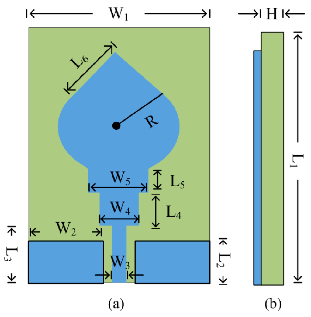
2.1. Design of Ultra-Wideband Antenna
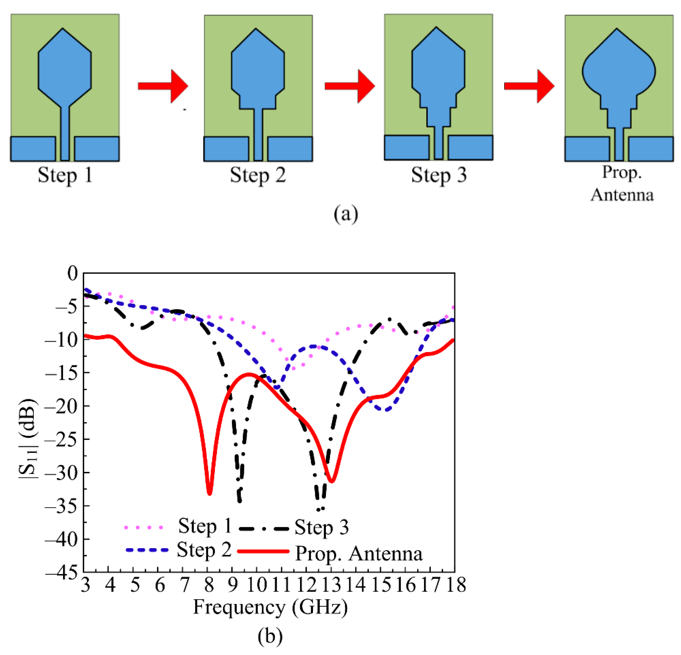
2.2. Design Stages of UWB Antenna
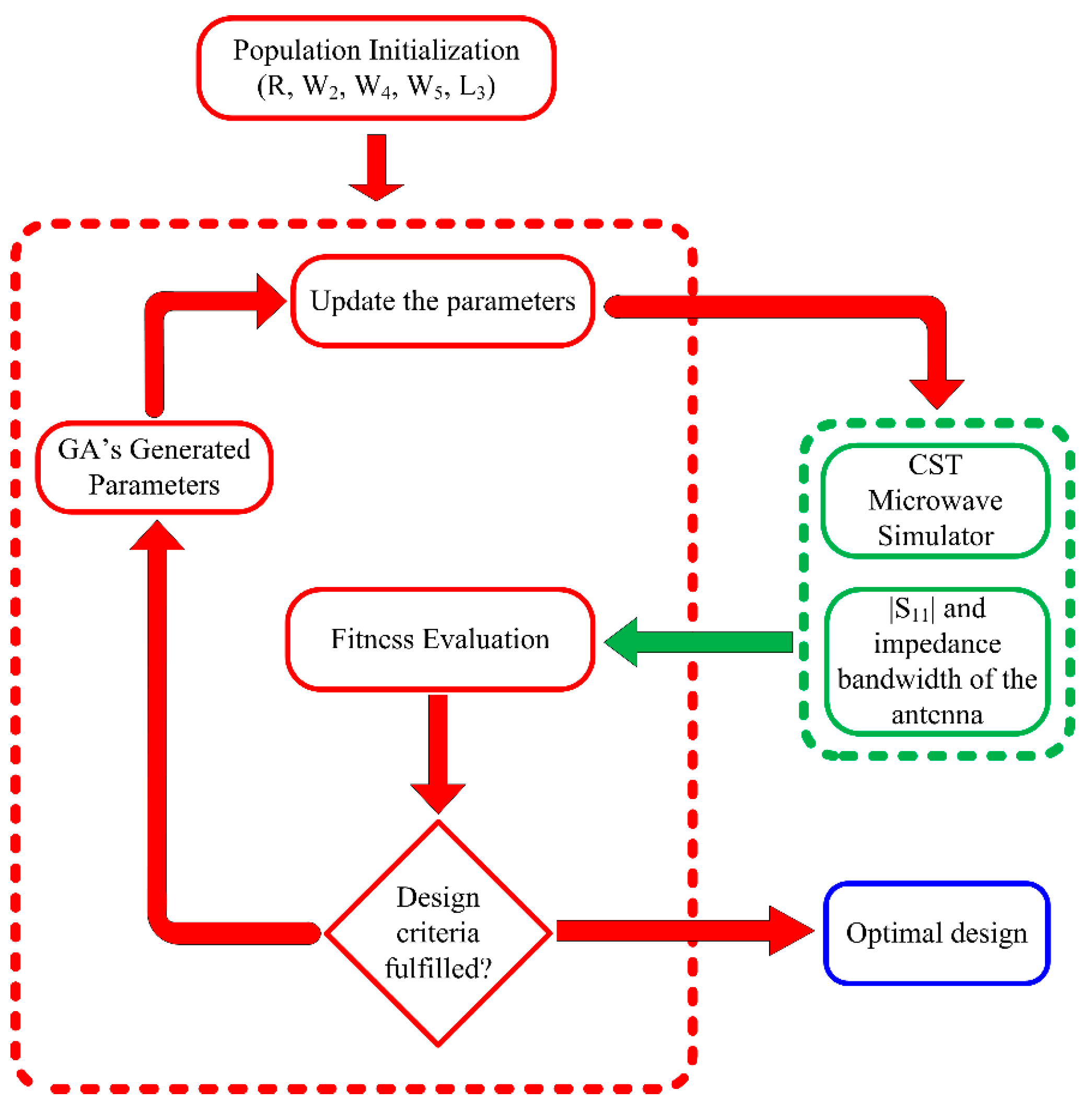
2.3. Optimization Algorithm
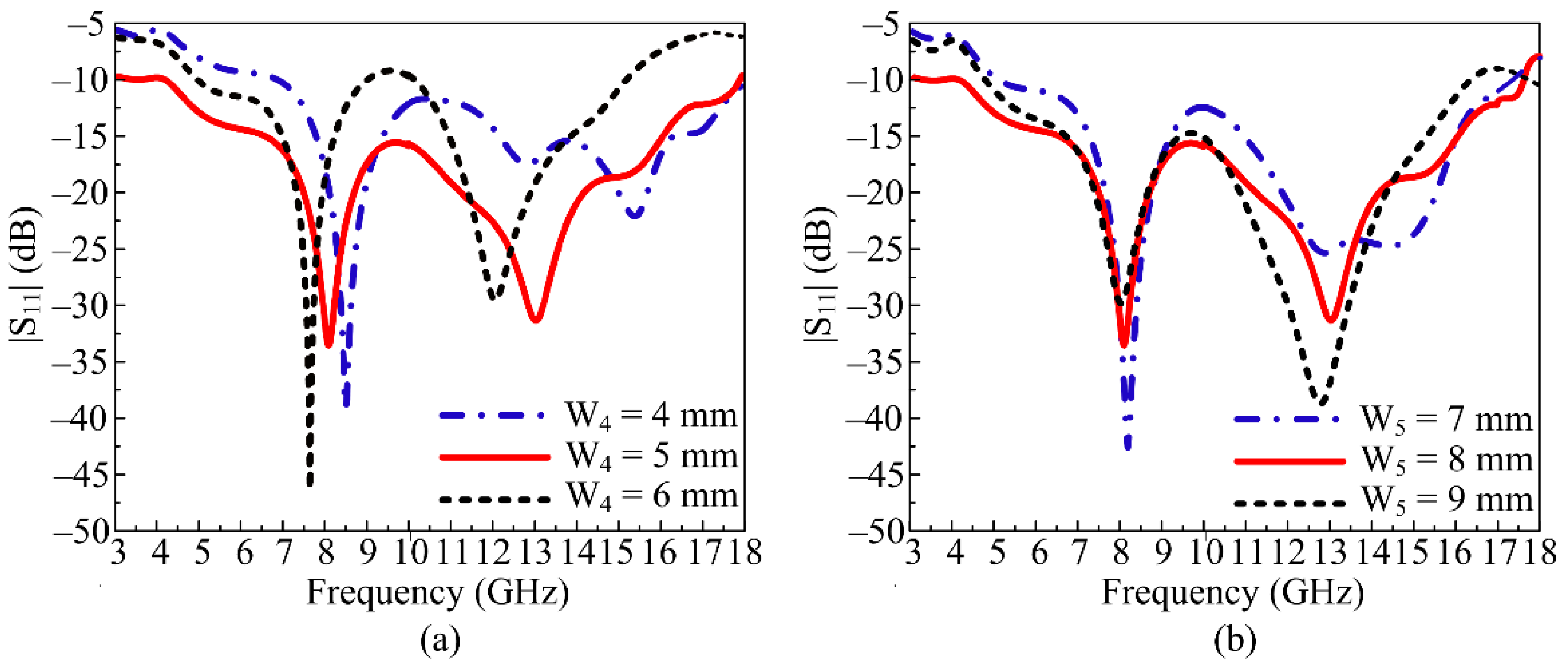
2.4. Parametric Analysis of Important Parameters
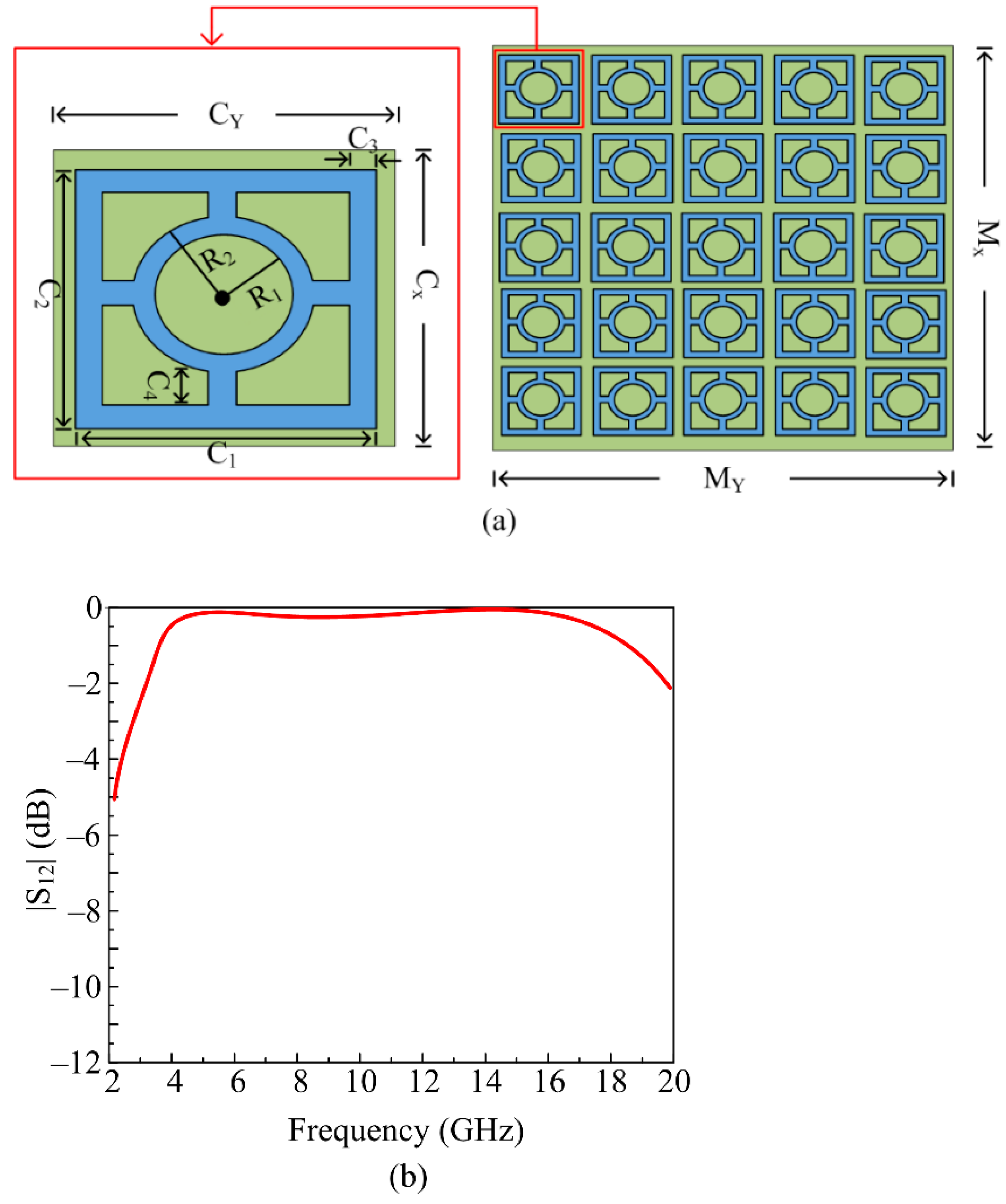
2.5. Design of Proposed Frequency Selective Surface (FSS)
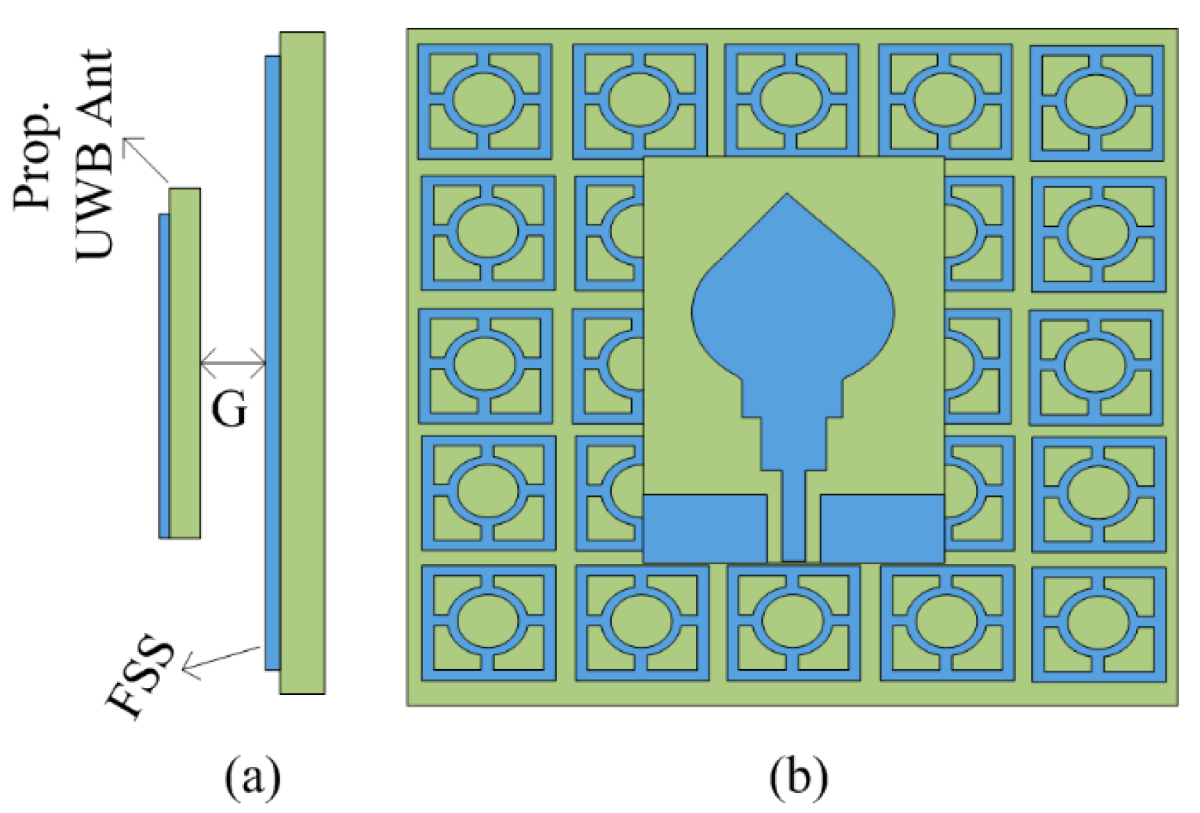
2.6. Proposed FSS-Loaded UWB Antenna and Its Radiation Mechanism
3. Results
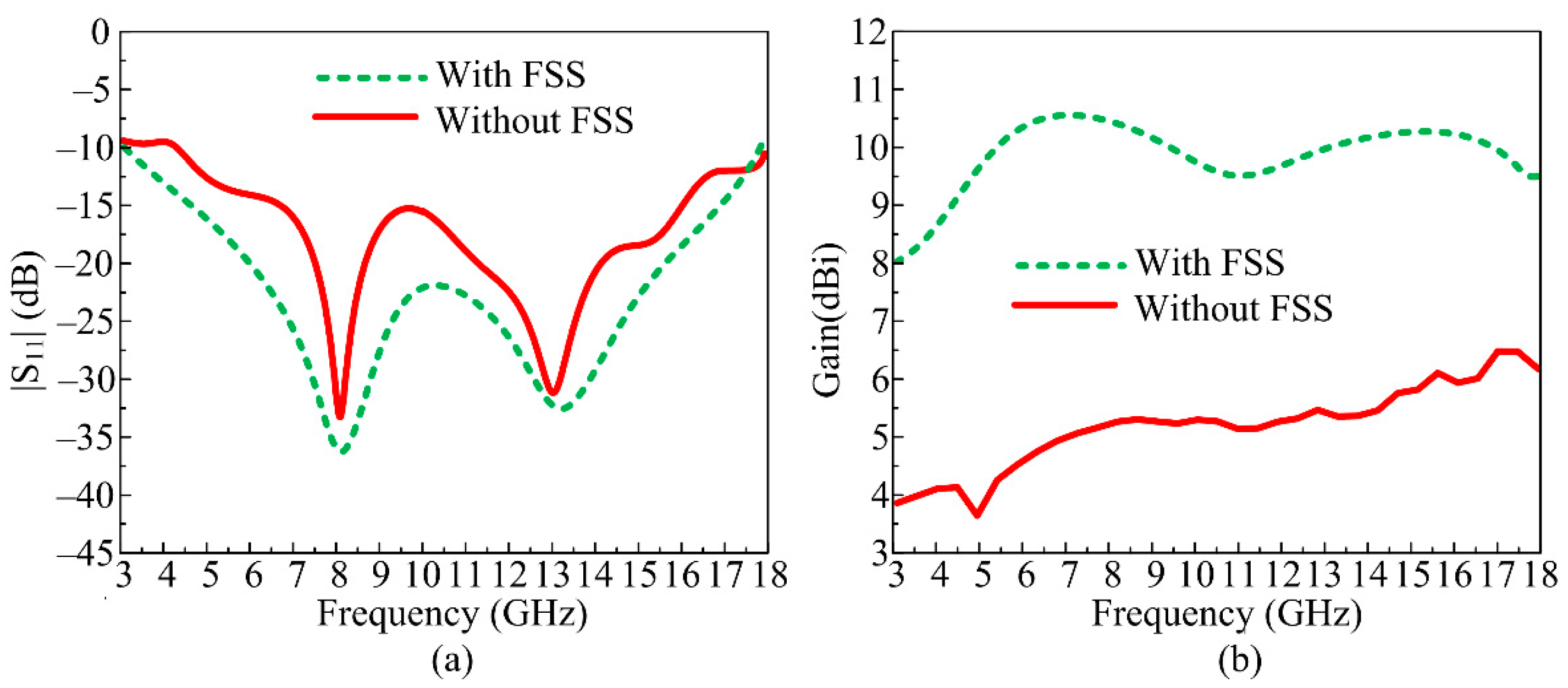
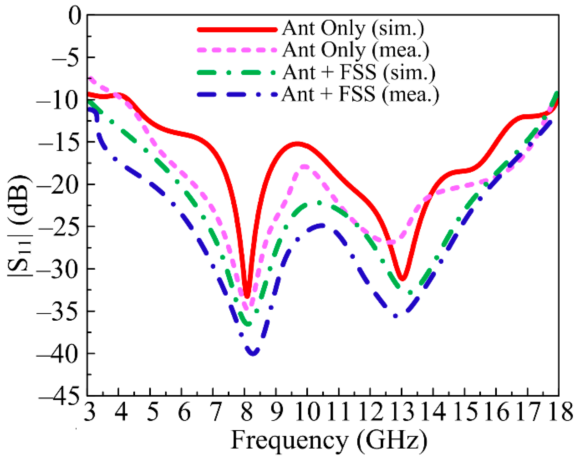
3.1. S-Parameters
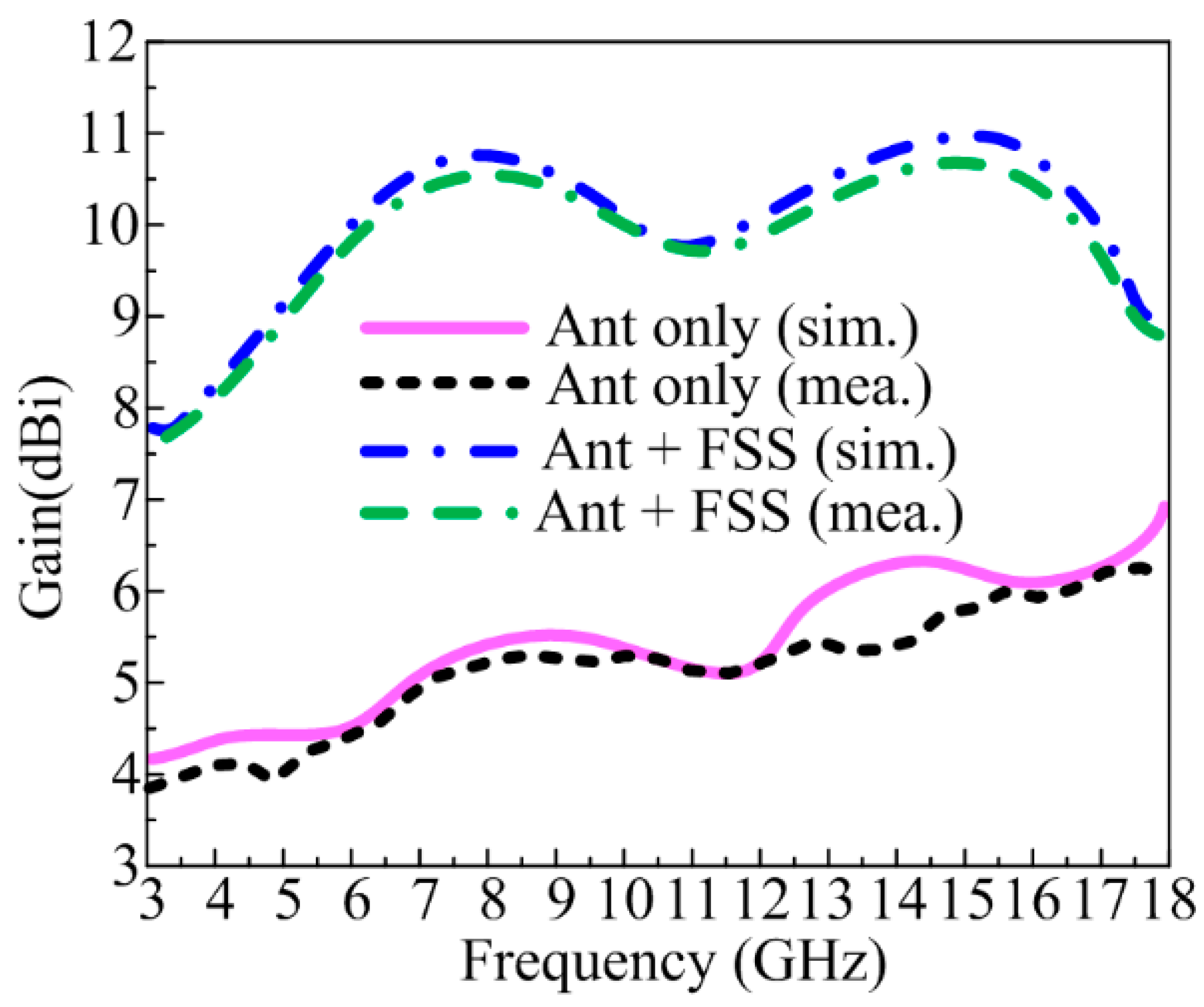
3.2. Gain of Antenna with and without FSS
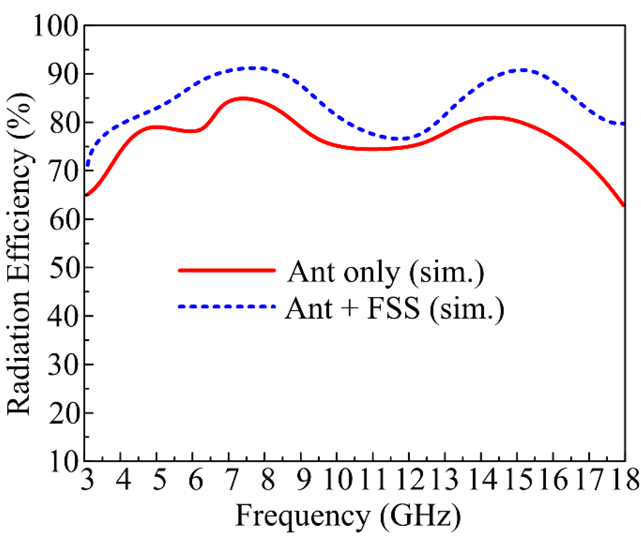
3.3. Radiation Efficiency
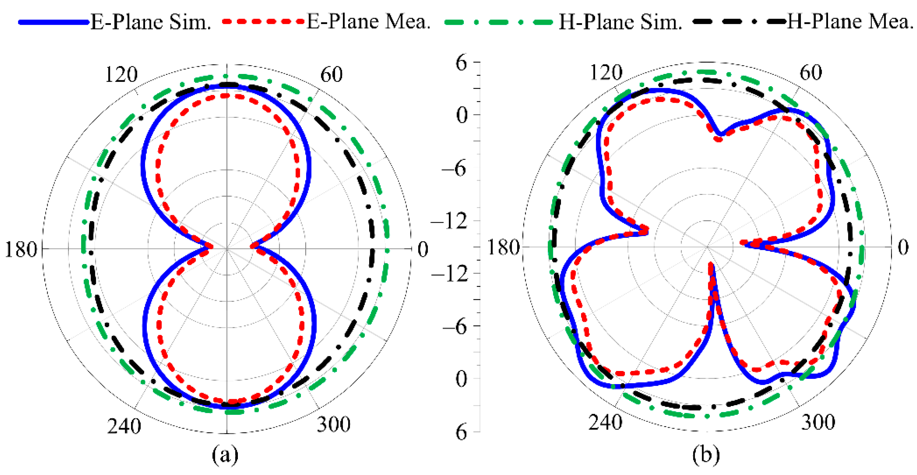
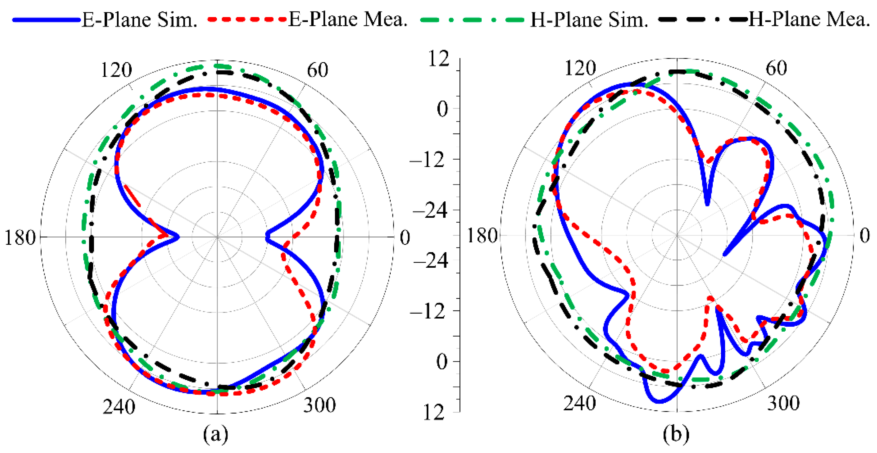
3.4. Radiation Pattern of Proposed Work
3.5. Comparison with State-of-the-Art

| Ref | Overall Antenna Size (λ × λ × λ) | Volume of Antenna (mm3) | Operational Bandwidth (GHz) | Gain without FSS (dBi) | Gain with FSS (dBi) | No. of FSS Layers |
|---|---|---|---|---|---|---|
| [19] | 0.31 × 0.61 × 0.1 | 37,210 | 3–11.9 | 3.65 | 7.8 | Single |
| [20] | 0.65 × 0.65 × 0.45 | 156,282 | 3.6–3.9 | 2 | 3 | Single |
| [21] | 0.5 × 0.51 × 0.1 | 25,190 | 2.9–9.3 | 3.12 | 5.12 | Single |
| [23] | 0.99 × 0.99 × 0.33 | 305,407 | 3.6–6.1 | 3.8 | 7.8 | Single |
| [26] | 0.85 × 0.85 × 0.27 | 195,075 | 3–12 | 2.8 | 6.6 | Single |
| [27] | 0.53 × 0.65 × 0.24 | 75,400 | 3.1–18.6 | 2.7 | 6.9 | Single |
| [28] | 0.75 × 0.75 × 0.15 | 149,737 | 2.5–11 | 6.5 | 8.5 | Single |
| [30] | 0.54 × 0.54 × 0.19 | 52,543 | 3.16–15 | 4 | 8.9 | Single |
| [31] | 0.44 × 0.44 × 0.2 | 38,720 | 3–14.6 | 4.5 | 8.7 | Double |
| [32] | 0.44 × 0.44 × 0.33 | 64,856 | 3.05–13.4 | 4.2 | 8.5 | Double |
| [35] | 0.48 × 0.48 × 0.3 | 57,600 | 3–21 | 4.8 | 7.2 | Single |
| [37] | 0.79 × 0.79 × 0.2 | 115,596 | 3.1–13.9 | 4.9 | 9.7 | Single |
| [43] | 0.9 × 0.9 × 0.13 | 53,900 | 3.7–11 | 6 | 9 | Single |
| This Work | 0.5 × 0.5 × 0.09 | 31,000 | 3–18 | 6.5 | 10.5 | Single |
4. Conclusions
Author Contributions
Funding
Data Availability Statement
Acknowledgments
Conflicts of Interest
References
- Vannithamby, R.; Talwar, S. Towards 5G: Applications, Requirements and Candidate Technologies; John Wiley & Sons: Hoboken, NJ, USA, 2017; ISBN 978-1-118-97991-4. [Google Scholar]
- Ali, E.M.; Awan, W.A.; Naqvi, S.I.; Alzaidi, M.S.; Alzahrani, A.; Elkamchouchi, D.H.; Falcone, F.; Alharbi, T.E.A. A low-profile antenna for on-body and off-body applications in the lower and upper ISM and WLAN bands. Sensors 2023, 23, 709. [Google Scholar] [CrossRef] [PubMed]
- Awan, W.A.; Naqvi, S.I.; Naqvi, A.H.; Abbas, S.M.; Zaidi, A.; Hussain, N. Design and characterization of wideband printed antenna based on DGS for 28 GHz 5G applications. J. Electromag. Eng. Sci. 2021, 21, 177–183. [Google Scholar] [CrossRef]
- Awan, W.A.; Alibakhshikenari, M.; Limiti, E. A Poly-Di-Methyl-Siloxane based conformal ultra-wideband antenna with additional GSM band. In Proceedings of the 2021 IEEE Asia-Pacific Microwave Conference (APMC), Brisbane, Australia, 28 November–1 December 2021; pp. 67–69. [Google Scholar]
- Altaf, A.; Elahi, M.; Abbas, S.M.; Yousaf, J.; Almajali, E. A D-band waveguide-SIW transition for 6G applications. J. Electromag. Eng. Sci. 2022, 22, 419–426. [Google Scholar] [CrossRef]
- Ali, E.M.; Awan, W.A.; Alizaidi, M.S.; Alzahrani, A.; Elkamchouchi, D.H.; Falcone, F.; Ghoneim, S.S.M. A shorted stub loaded UWB flexible antenna for small IoT devices. Sensors 2023, 23, 748. [Google Scholar] [CrossRef]
- Krishna, R.V.S.R.; Kumar, R. A Dual-Polarized square-ring slot antenna for UWB, imaging, and radar applications. IEEE Antennas Wirel. Propag. Lett. 2016, 15, 195–198. [Google Scholar] [CrossRef]
- Zaidi, A.; Awan, W.A.; Ghaffar, A.; Alzaidi, M.S.; Alsharef, M.; Elkamchouchi, D.H.; Ghoneim, S.S.M.; Alharbi, T.E.A. A low profile ultra-wideband antenna with reconfigurable notch band characteristics for smart electronic systems. Micromachines 2022, 13, 1803. [Google Scholar] [CrossRef]
- Abbas, M.A.; Cengiz, M.F.; Allam, A.M.M.A.; Fawzy, D.E.; Elhennawy, H.M.; Sree, M.F.A. A novel circular reconfigurable Metasurface-based compact UWB hybrid coupler for Ku-band applications. IEEE Access 2022, 10, 129781–129790. [Google Scholar] [CrossRef]
- Ibrahim, A.A.; Abo Sree, M.F. UWB MIMO antenna with 4-element, compact size, high isolation and single band rejection for high-speed wireless networks. Wirel. Netw. 2022, 28, 3143–3155. [Google Scholar] [CrossRef]
- Ryu, K.S.; Kishk, A.A. UWB dielectric resonator antenna having consistent omnidirectional pattern and low cross-polarization characteristics. IEEE Trans. Antennas Propag. 2011, 59, 1403–1408. [Google Scholar] [CrossRef]
- Wang, J.; Yin, Y. Differential-fed UWB microstrip antenna with improved radiation patterns. Electron. Lett. 2014, 50, 1412–1414. [Google Scholar] [CrossRef]
- Hsieh, T.H.; Lee, C.S. Double-layer high-gain microstrip array antenna. IEEE Trans. Antennas Propag. 2000, 48, 1033–1035. [Google Scholar] [CrossRef]
- Lalbakhsh, A.; Esselle, K.P. Directivity improvement of a Fabry-Perot cavity antenna by enhancing near field characteristic. In Proceedings of the 2016 17th International Symposium on Antenna Technology and Applied Electromagnetics (ANTEM), Montreal, QC, Canada, 10–13 July 2016; pp. 1–2. [Google Scholar]
- Esfandiari, M.; Lalbakhsh, A.; Shehni, P.N.; Jarchi, S.; Ghaffari-Miab, M.; Mahtaj, H.N.; Reisenfeld, S.; Alibakhshikenari, M.; Koziel, S.; Szczepanski, S. Recent and emerging applications of Graphene-based metamaterials in electromagnetics. Materials Design 2022, 221, 110920. [Google Scholar] [CrossRef]
- Lalbakhsh, A.; Simorangkir, R.B.; Bayat-Makou, N.; Kishk, A.A.; Esselle, K.P. Advancements and artificial intelligence approaches in antennas for environmental sensing. Artif. Intell. Data Sci. Environ. Sens. 2022, 19–38. [Google Scholar] [CrossRef]
- Tariq, S.; Naqvi, S.I.; Hussain, N.; Amin, Y. A metasurface-based MIMO antenna for 5G millimeter-wave applications. IEEE Access 2021, 9, 51805–51817. [Google Scholar] [CrossRef]
- Hussain, N.; Naqvi, S.I.; Awan, W.A.; Le, T.T. A metasurface-based wideband bidirectional same-sense circularly polarized antenna. Int. J. RF Microw. Comp. Aided. Eng. 2020, 30, 22262. [Google Scholar] [CrossRef]
- Al-Gburi, A.J.A.; Ibrahim, I.B.M.; Zeain, M.Y.; Zakaria, Z. Compact size and high gain of CPW-fed UWB strawberry artistic shaped printed monopole antennas using FSS single layer reflector. IEEE Access 2020, 8, 92697–92707. [Google Scholar] [CrossRef]
- Kushwaha, N.; Kumar, R. Design of slotted ground hexagonal microstrip patch antenna and gain improvement with FSS screen. Prog. Electromag. Res. B 2013, 51, 177–199. [Google Scholar] [CrossRef] [Green Version]
- Mondal, K. Bandwidth and gain enhancement of microstrip antenna by frequency selective surface for WLAN, WiMAX applications. Sādhanā 2019, 44, 1–10. [Google Scholar] [CrossRef] [Green Version]
- Das, P.; Mandal, K. Modelling of ultra-wide stop-band frequency-selective surface to enhance the gain of a UWB antenna. IET Microw. Antennas Propag. 2019, 13, 269–277. [Google Scholar] [CrossRef]
- Kumar, A.; De, A.; Jain, R.K. Gain Enhancement Using Modified Circular Loop FSS Loaded with Slot Antenna for Sub-6GHz 5G Application. Prog. Electromag. Res. Lett. 2021, 98, 41–49. [Google Scholar] [CrossRef]
- Asaadi, M.; Afifi, I.; Sebak, A.R. High gain and wideband high dense dielectric patch antenna using FSS superstrate for millimeter-wave applications. IEEE Access 2018, 6, 38243–38250. [Google Scholar] [CrossRef]
- Tahir, F.A.; Naqvi, A.H. A novel FSS for gain enhancement of printed antennas in UWB frequency spectrum. Microw. Opt. Technol. Lett. 2017, 59, 2698–2704. [Google Scholar] [CrossRef]
- Mondal, R.; Reddy, P.S.; Sarkar, D.C.; Sarkar, P.P. Compact ultra-wideband antenna: Improvement of gain and FBR across the entire bandwidth using FSS. IET Microw. Antennas Propag. 2020, 14, 66–74. [Google Scholar] [CrossRef]
- Yuan, Y.; Xi, X.; Zhao, Y. Compact UWB FSS reflector for antenna gain enhancement. IET Microw. Antennas Propag. 2019, 13, 1749–1755. [Google Scholar] [CrossRef]
- Awan, W.A.; Choi, D.M.; Hussain, N.; Elfergani, I.; Park, S.G.; Kim, N. A Frequency Selective Surface Loaded UWB Antenna for High Gain Applications. Comput. Mater. Contin. 2022, 73, 6169–6180. [Google Scholar]
- Abdulhasan, R.A.; Alias, R.; Ramli, K.N.; Seman, F.C.; Alhameed, R.A.A. High gain CPW-fed UWB planar monopole antenna-based compact uniplanar frequency selective surface for microwave imaging. Int. J. RF Microw. Comp. Aided. Eng. 2019, 29, 21757. [Google Scholar] [CrossRef] [Green Version]
- Swetha, A.; Naidu, K.R. Gain enhancement of an UWB antenna based on a FSS reflector for broadband applications. Prog. Electromagn. Res. C 2020, 99, 193–208. [Google Scholar] [CrossRef] [Green Version]
- Kundu, S.; Chatterjee, A.; Jana, S.K.; Paru, S.K. Gain enhancement of a printed leaf shaped UWB antenna using dual FSS layers and experimental study for ground coupling GPR applications. Microw. Opt. Technol. Lett. 2016, 60, 1417–1423. [Google Scholar] [CrossRef]
- Kundu, S.; Chatterjee, A.; Jana, S.K.; Paru, S.K. A compact umbrella shaped UWB antenna with gain augmentation using frequency selective surface. Radioengineering 2018, 27, 448–454. [Google Scholar] [CrossRef]
- Lalbakhsh, A.; Afzal, M.U.; Hayat, T.; Esselle, K.P.; Mandal, K. All-metal wideband metasurface for near-field transformation of medium-to-high gain electromagnetic sources. Sci. Rep. 2021, 11, 9421. [Google Scholar] [CrossRef]
- Kundu, S. A compact uniplanar ultra-wideband frequency selective surface for antenna gain improvement and ground penetrating radar application. Int. J. RF Microw. Comput.-Aided Eng. 2020, 30, e22363. [Google Scholar] [CrossRef]
- Kundu, S. High gain compact ultra-wideband antenna-frequency selective surface and its performance evaluation in proximity of soil surface. Microw. Opt. Technol. Lett. 2021, 63, 869–875. [Google Scholar] [CrossRef]
- Lalbakhsh, A.; Afzal, M.U.; Esselle, K.P.; Smith, S.L. A high-gain wideband EBG resonator antenna for 60 GHz unlicenced frequency band. In Proceedings of the 12th European Conference on Antennas and Propagation (EuCAP 2018), London, UK, 9–13 April 2018; pp. 1–3. [Google Scholar]
- Melouki, N.; Hocini, A.; Denidni, T.A. Performance enhancement of an ultra-wideband antenna using a compact topology optimized single frequency selective surface-layer as a reflector. Int. J. RF Microw. Comp. Aided. Eng. 2022, 32, e23097. [Google Scholar] [CrossRef]
- Nishanth, R.K.; Meshram, V.; Suresh, H.N. SSA Based Microstrip Patch Antenna Design with FSS for UWB Application. Wirel. Pers. Commun. 2022, 123, 2533–2553. [Google Scholar] [CrossRef]
- Awan, W.A.; Zaidi, A.; Hussain, M.; Hussain, N.; Syed, I. The design of a wideband antenna with notching characteristics for small devices using a genetic algorithm. Mathematics 2021, 9, 2113. [Google Scholar] [CrossRef]
- Hocini, A.; Melouki, N.; Denidni, T.A. Modeling and simulation of an antenna with optimized AMC reflecting layer for gain and front-to-back ratio enhancement for 5G applications. J. Phys. Conf. Ser. 2020, 1492, 012006. [Google Scholar] [CrossRef]
- Nguyen, D.; Seo, C. Frequency-selective surface stopband designed with a genetic algorithm for gain enhancement of a broadband monopole antenna. J. Electromag. Eng. Sci. 2022, 22, 236–244. [Google Scholar] [CrossRef]
- Hussain, M.; Awan, W.A.; Alzaidi, M.S.; Hussain, N.; Ali, E.M.; Falcone, F. Metamaterials and their application in the performance enhancement of reconfigurable antennas: A review. Micromachines 2023, 14, 349. [Google Scholar] [CrossRef] [PubMed]
- Adibi, S.; Honarvar, M.A.; Lalbakhsh, A. Gain enhancement of wideband circularly polarized UWB antenna using FSS. Radio Sci. 2021, 56, 1–8. [Google Scholar] [CrossRef]


Disclaimer/Publisher’s Note: The statements, opinions and data contained in all publications are solely those of the individual author(s) and contributor(s) and not of MDPI and/or the editor(s). MDPI and/or the editor(s) disclaim responsibility for any injury to people or property resulting from any ideas, methods, instructions or products referred to in the content. |
© 2023 by the authors. Licensee MDPI, Basel, Switzerland. This article is an open access article distributed under the terms and conditions of the Creative Commons Attribution (CC BY) license (https://creativecommons.org/licenses/by/4.0/).
Share and Cite
Hussain, M.; Sufian, M.A.; Alzaidi, M.S.; Naqvi, S.I.; Hussain, N.; Elkamchouchi, D.H.; Sree, M.F.A.; Fatah, S.Y.A. Bandwidth and Gain Enhancement of a CPW Antenna Using Frequency Selective Surface for UWB Applications. Micromachines 2023, 14, 591. https://doi.org/10.3390/mi14030591
Hussain M, Sufian MA, Alzaidi MS, Naqvi SI, Hussain N, Elkamchouchi DH, Sree MFA, Fatah SYA. Bandwidth and Gain Enhancement of a CPW Antenna Using Frequency Selective Surface for UWB Applications. Micromachines. 2023; 14(3):591. https://doi.org/10.3390/mi14030591
Chicago/Turabian StyleHussain, Musa, Md. Abu Sufian, Mohammed S. Alzaidi, Syeda Iffat Naqvi, Niamat Hussain, Dalia H. Elkamchouchi, Mohamed Fathy Abo Sree, and Sara Yehia Abdel Fatah. 2023. "Bandwidth and Gain Enhancement of a CPW Antenna Using Frequency Selective Surface for UWB Applications" Micromachines 14, no. 3: 591. https://doi.org/10.3390/mi14030591