

A Frequency Reconfigurable Folded Antenna for Cognitive Radio Communication


Abstract
:1. Introduction
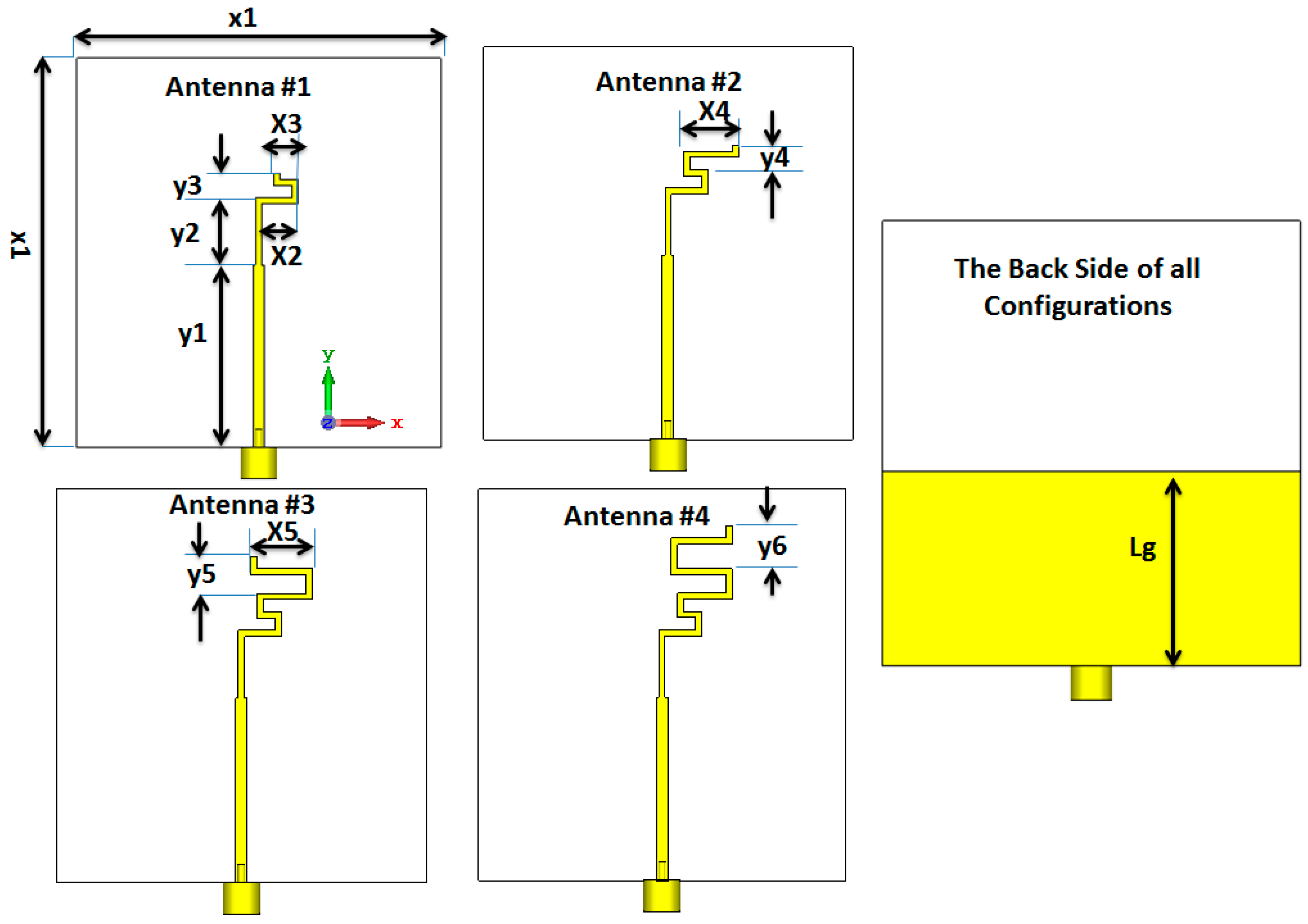
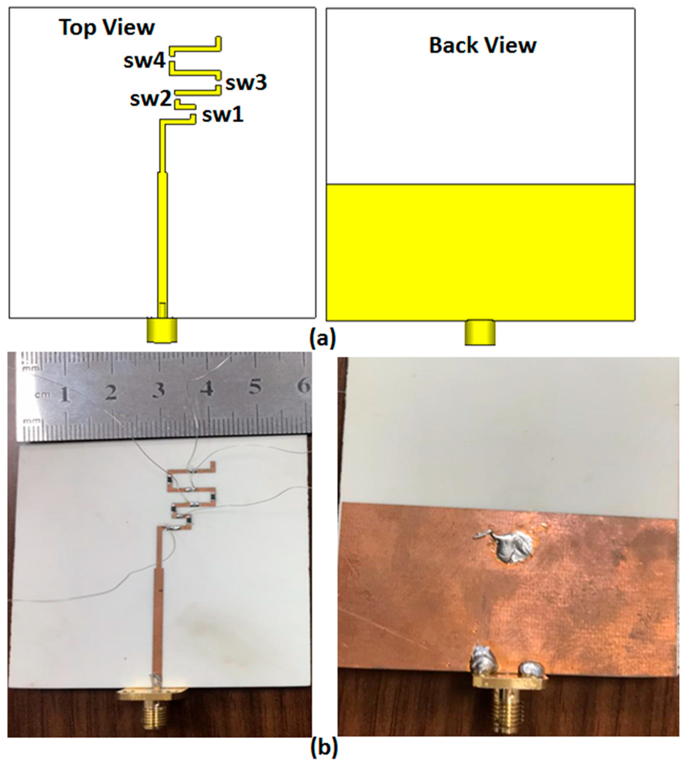
2. Folded Antenna
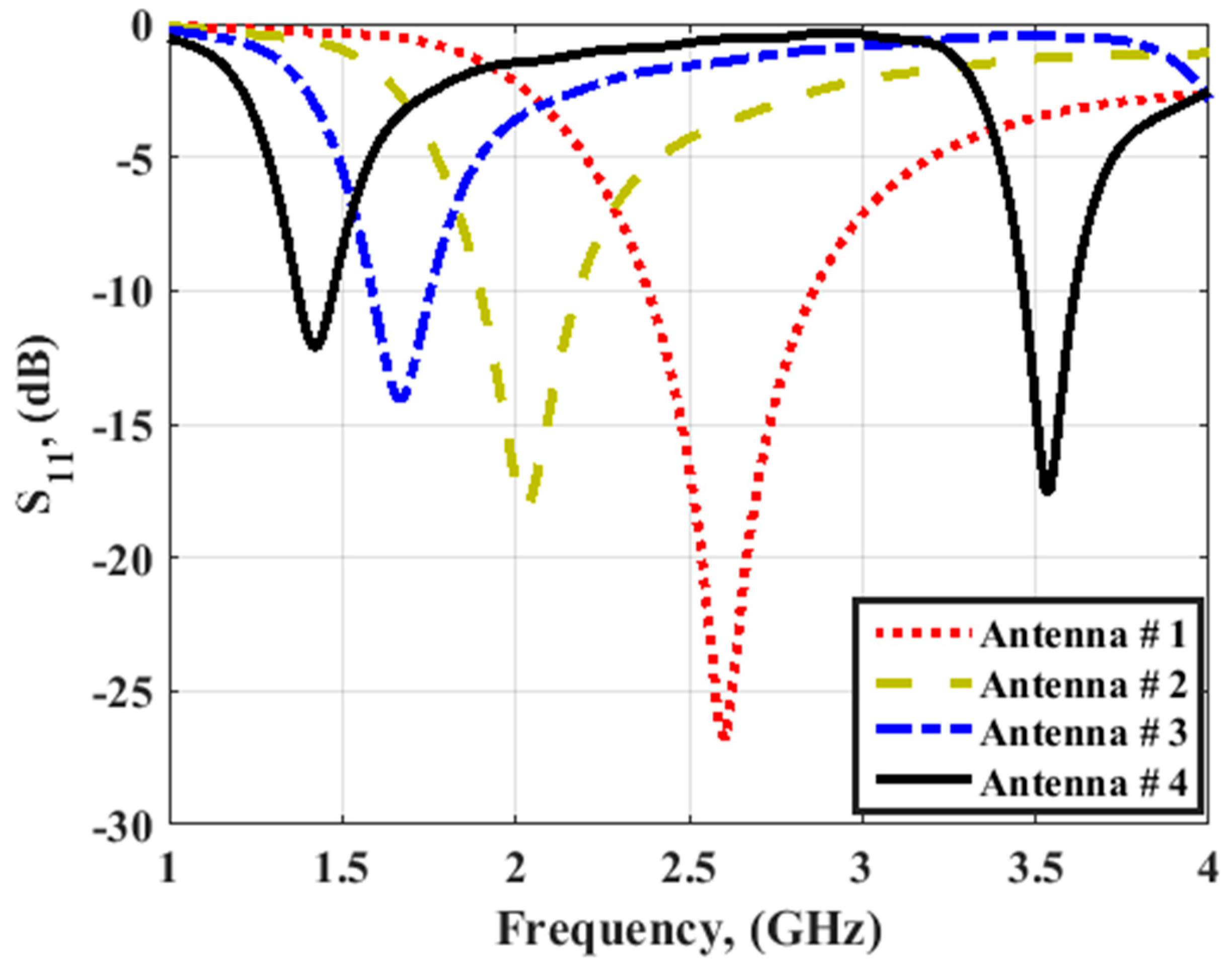
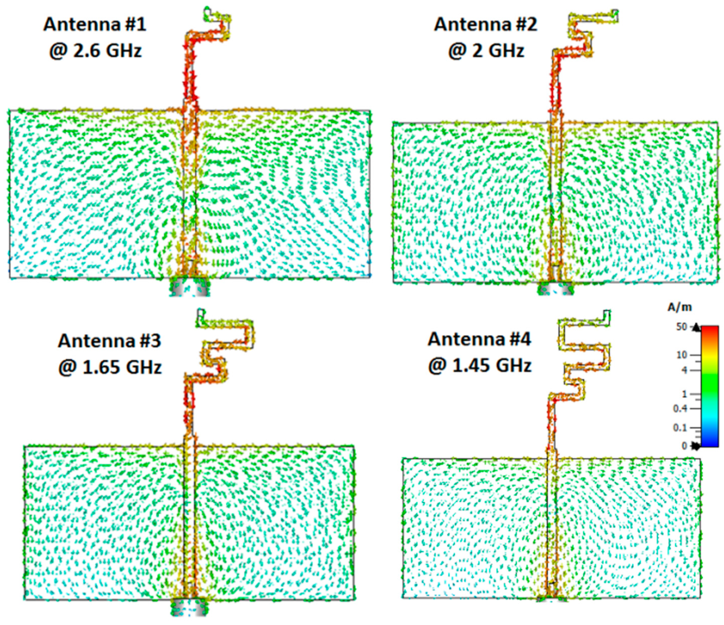
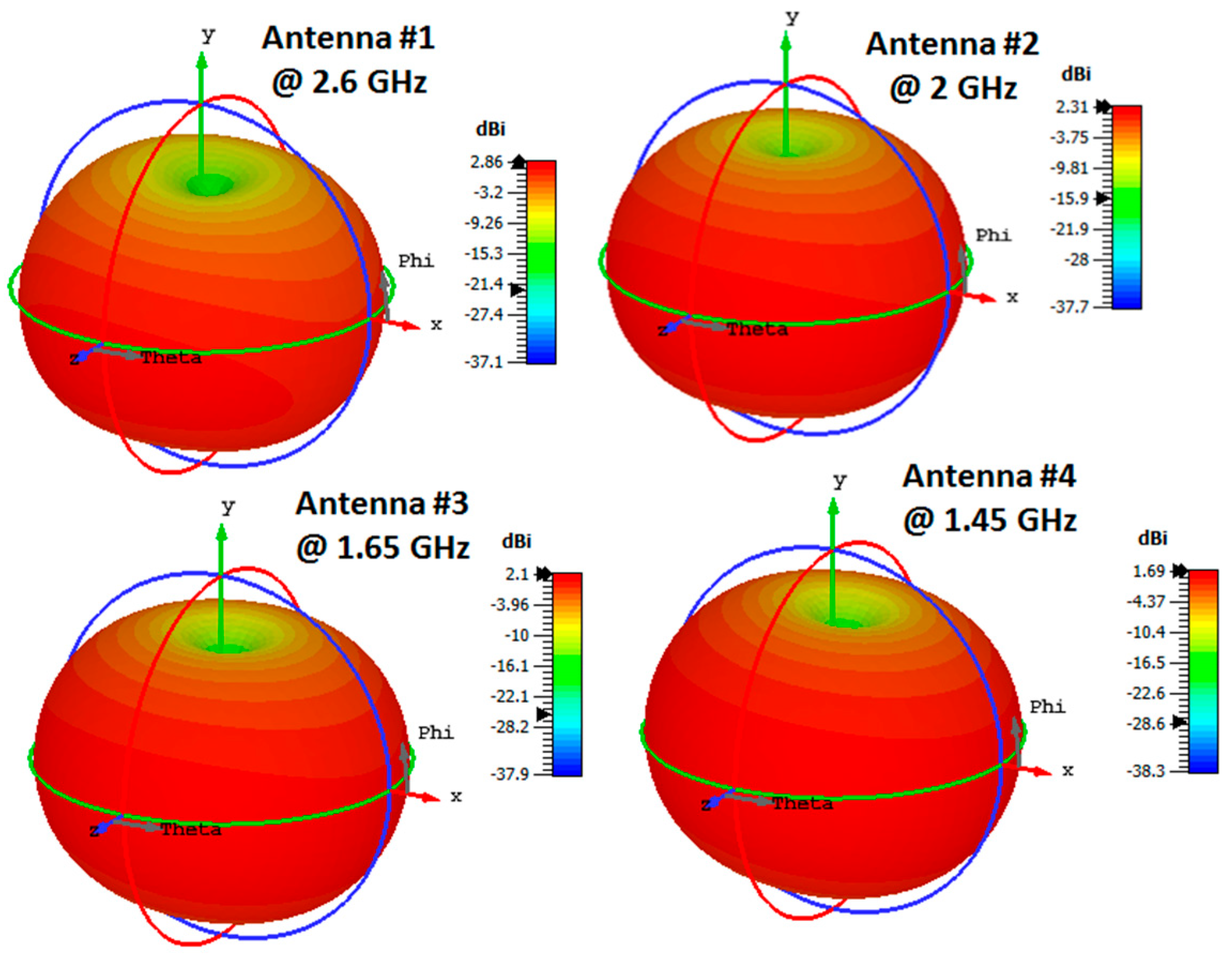
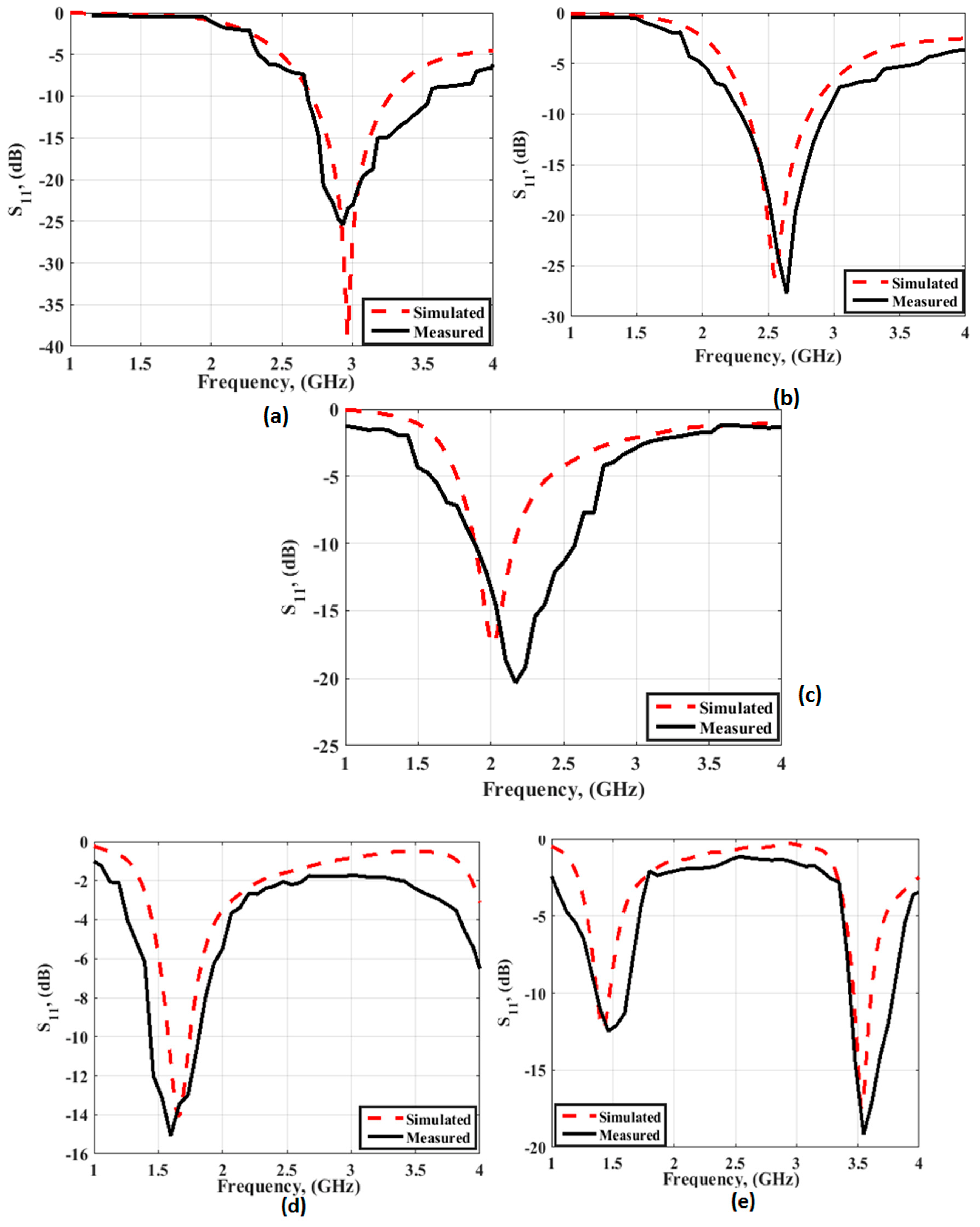
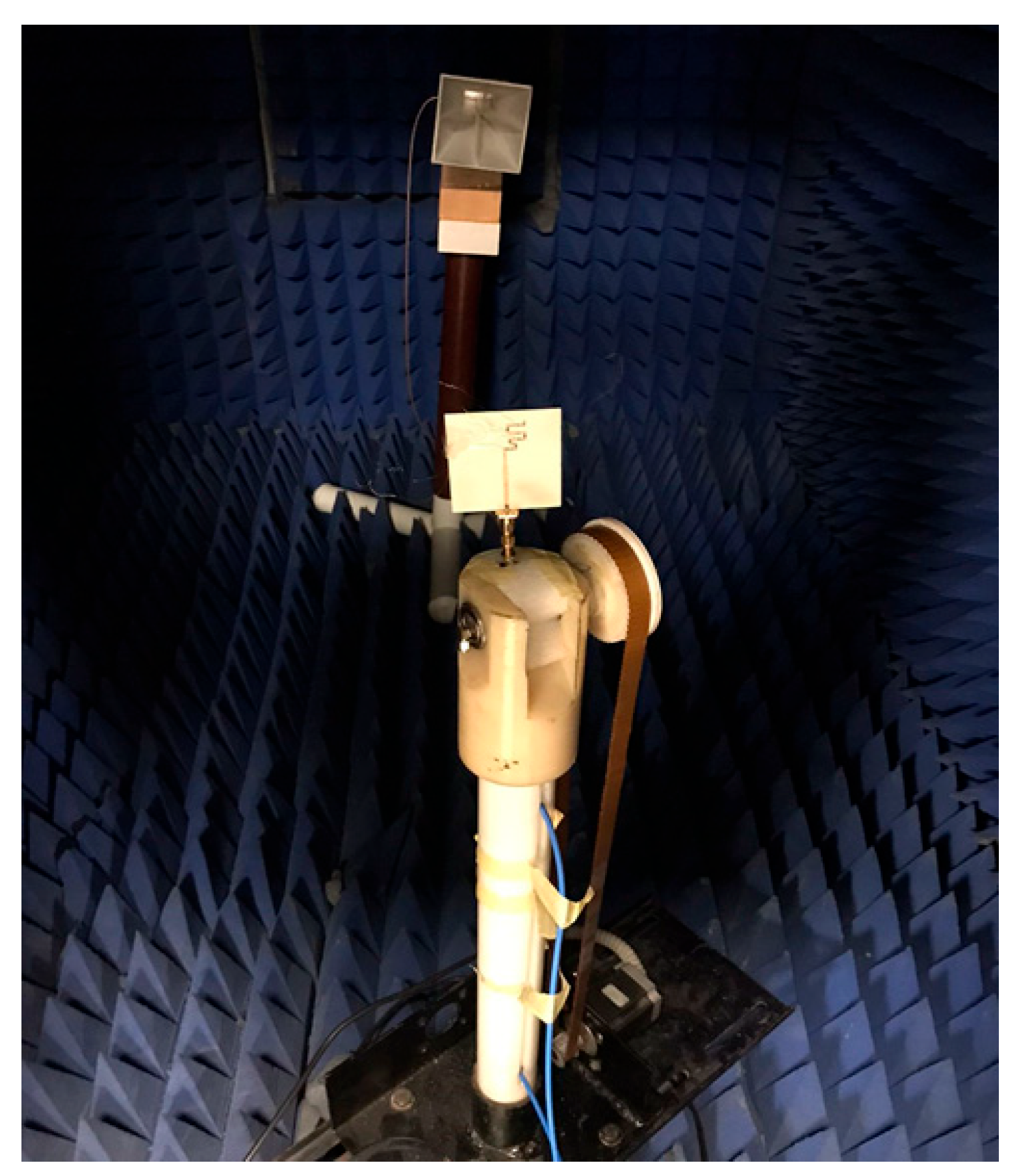
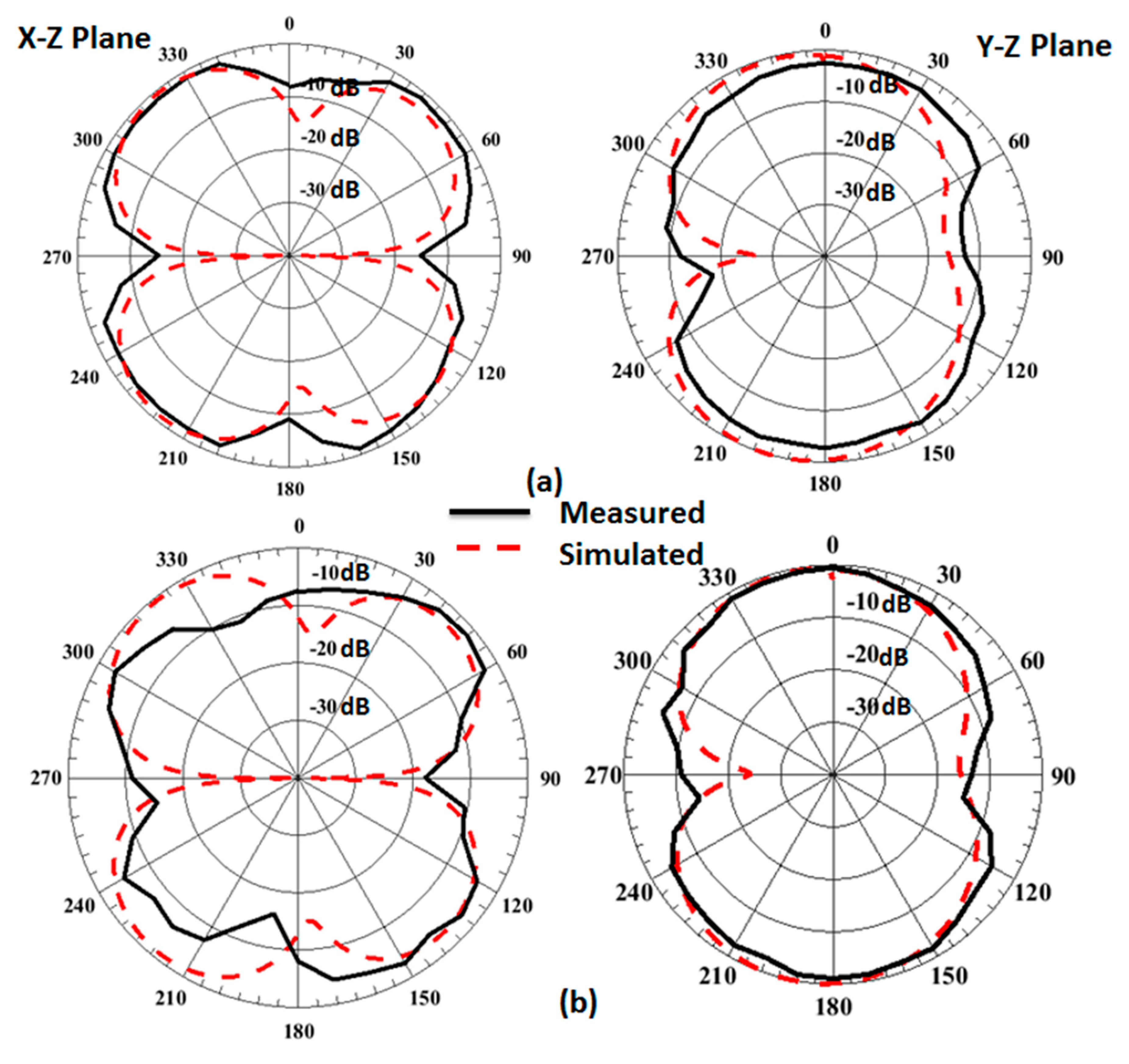
3. The Results of the Suggested Configuration
4. Conclusions
Author Contributions
Funding
Data Availability Statement
Conflicts of Interest
References
- Kumar, O.P.; Kumar, P.; Ali, T.; Kumar, P.; Vincent, S. Ultrawideband Antennas: Growth and Evolution. Micromachines 2021, 13, 60. [Google Scholar] [CrossRef] [PubMed]
- Mathur, R.; Dwari, S. Compact CPW-Fed ultrawideband MIMO antenna using hexagonal ring monopole antenna elements. AEU Int. J. Electron. Commun. 2018, 93, 1–6. [Google Scholar] [CrossRef]
- Hu, Y.; Du, K.; Zhang, L.; Wang, Y.; Kang, X. A Design for a Wide-Band Antenna Pair Applied for Mobile Terminals at the Sub-6 GHz Band. Appl. Sci. 2022, 13, 331. [Google Scholar] [CrossRef]
- Alaa, A.M.; Ismail, M.H.; Tawfik, H. Spectrum sensing via reconfigurable antennas: Fundamental limits and potential gains. Telecommun. Syst. 2016, 62, 581–602. [Google Scholar] [CrossRef]
- Ibrahim, A.A.; Mohamed, H.A.; Rizo, A.R.D.; Parra-Michel, R.; Aboushady, H. Tunable Filtenna With DGS Loaded Resonators for a Cognitive Radio System Based on an SDR Transceiver. IEEE Access 2022, 10, 32123–32131. [Google Scholar] [CrossRef]
- Wang, X.; Wu, Y.; Wang, W.; Kishk, A.A. A simple multi-broadband planar antenna for LTE/GSM/UMTS and WLAN/WiMAX mobile handset applications. IEEE Access 2018, 6, 74453–74461. [Google Scholar] [CrossRef]
- Yang, L.; Cui, Y.-H.; Li, R.-L. A multiband uniplanar antenna for LTE/GSM/UMTS, GPS, and WLAN/WiMAX handsets. Microw. Opt. Technol. Lett. 2015, 57, 2761–2765. [Google Scholar] [CrossRef]
- Affandi, A.; Azim, R.; Alam, M.; Islam, M.T. A Low-Profile Wideband Antenna for WWAN/LTE Applications. Electronics 2020, 9, 393. [Google Scholar] [CrossRef] [Green Version]
- Nayak, P.B.; Verma, S.; Kumar, P. Multiband fractal antenna design for Cognitive radio applications. In Proceedings of the International Conference on Signal Processing and Communication (ICSC), Noida, India, 12–14 December 2013; pp. 115–120. [Google Scholar]
- Wang, L.; Yu, J.; Xie, T.; Bi, K. A Novel Multiband Fractal Antenna for Wireless Application. Int. J. Antennas Propag. 2021, 2021, 9926753. [Google Scholar] [CrossRef]
- David, R.; Aw, M.; Ali, T.; Kumar, P. A Multiband Antenna Stacked with Novel Metamaterial SCSRR and CSSRR for WiMAX/WLAN Applications. Micromachines 2021, 12, 113. [Google Scholar] [CrossRef]
- Yu, Z.; Li, Y.; Lin, Z.; Ran, X. Design of Window Grille Shape-Based Multiband Antenna for Mobile Terminals. Int. J. Antennas Propag. 2021, 2021, 6684959. [Google Scholar] [CrossRef]
- Patel, R.; Desai, A.; Upadhyaya, T.; Nguyen, T.K.; Kaushal, H.; Dhasarathan, V. Meandered low profile multiband antenna for wireless communication applications. Wirel. Netw. 2020, 27, 1–12. [Google Scholar] [CrossRef]
- Mishra, R.; Dandotiya, R.; Kapoor, A.; Kumar, P.; Zhang, Z.; Liu, J.; Su, J.; Song, J.; Gao, Y.; Peng, W.; et al. Compact high gain multiband antenna based on split ring resonator and inverted F slots for 5G industry applications. Appl. Comput. Electromagn. Soc. 2021, 36, 999–1007. [Google Scholar] [CrossRef]
- Dayo, Z.; Cao, Q.; Wang, Y.; Soothar, P.; Khoso, I.; Shah, G.; Aamir, M.; Kaburcuk, F.; Kalinay, G.; Chen, Y.; et al. A compact high gain multiband bowtie slot antenna with miniaturized triangular shaped metallic ground plane. Appl. Comput. Electromagn. Soc. 2021, 36, 935–945. [Google Scholar] [CrossRef]
- Salamin, M.A.; Ali, W.; Zugari, A. Design and analysis of a miniaturized band-notched planar antenna incorporating a joint DMS and DGS band-rejection technique for UWB applications. Microsyst. Technol. 2018, 25, 3375–3385. [Google Scholar] [CrossRef]
- Salamin, M.; Ali, W.; Zugari, A. A novel UWB antenna using capacitively-loaded fork-shaped resonator and modified fork-shaped DMS for interference mitigation with WiMAX and WLAN applications. J. Instrum. 2019, 14, P03008. [Google Scholar] [CrossRef]
- Ghaffar, A.; Li, X.; Awan, W.; Naqvi, A.; Hussain, N.; Alibakhshikenari, M.; Limiti, E. A Flexible and Pattern Reconfigurable Antenna with Small Dimensions and Simple Layout for Wireless Communication Systems Operating over 1.65–2.51 GHz. Electronics 2021, 10, 601. [Google Scholar] [CrossRef]
- Ali, W.A.E.; Moniem, R.M.A. Frequency reconfigurable triple band-notched ultra-wideband antenna with compact size. Prog. Electromagn. Res. C 2017, 73, 37–46. [Google Scholar] [CrossRef] [Green Version]
- Islam, H.; Das, S.; Ali, T.; Bose, T.; Prakash, O.; Kumar, P. A Frequency Reconfigurable MIMO Antenna with Bandstop Filter Decoupling Network for Cognitive Communication. Sensors 2022, 22, 6937. [Google Scholar] [CrossRef]
- Zaidi, A.; Awan, W.A.; Ghaffar, A.; Alzaidi, M.S.; Alsharef, M.; Elkamchouchi, D.H.; Ghoneim, S.S.M.; Alharbi, T.E.A. A Low Profile Ultra-Wideband Antenna with Reconfigurable Notch Band Characteristics for Smart Electronic Systems. Micromachines 2022, 13, 1803. [Google Scholar] [CrossRef]
- Abdelghany, M.A.; Ali, W.A.E.; Mohamed, H.A.; Ibrahim, A.A. Filtenna with Frequency Reconfigurable Operation for Cognitive Radio and Wireless Applications. Micromachines 2023, 14, 160. [Google Scholar] [CrossRef] [PubMed]
- Rouissi, I.; Trad, I.B.; Floc’h, J.M.; Rmili, H.; Trabelsi, H. Design of frequency reconfigurable triband antenna using capacitive loading for wireless communications. In Proceedings of the 2015 Loughborough Antennas & Propagation Conference (LAPC), Loughborough, UK, 2–3 November 2015; pp. 1–5. [Google Scholar]
- Lee, M.; Ahn, J.; Kim, Y. Compact dual-band antenna with a lumped capacitor for wireless local area network applications. IET Microw. Antennas Propag. 2015, 9, 1747–1754. [Google Scholar] [CrossRef]
- Cleetus, R.M.C.; Bala, G.J. Wide-narrow switchable bands microstrip antenna for cognitive radios. Prog. Electromagn. Res. C 2020, 98, 225–238. [Google Scholar] [CrossRef] [Green Version]


| Ref. | εr/h (mm) | Size (mm2) | fo (GHz) | No.# of Freqs. | Actuators |
|---|---|---|---|---|---|
| [18] | 2.1/0.254 | 40 × 50 | 1.8, 2.1 | 2 | 2 PIN diodes |
| [19] | 4.4/1.6 | 20 × 20 | 3.6, 5.5, 8.1 | 3 | 2 PIN diodes |
| [20] | 4.4/1.6 | 48 × 24 | 1.77, 4.75 | 2 | 1 PIN diode |
| [21] | 4.5/1.524 | 17 × 23 | 3.5, 5.2 | 2 | 2 PIN diodes |
| [22] | 3.38/0.813 | 80 × 80 | 2.16, 2.8, 3 | 3 | 4 varactor diodes |
| [23] | 2.2/1.6 | 80 × 80 | 1.51, 1.91, 2.45 | 3 | 2 lumped capacitors |
| [24] | 4.4/0.8 | 65 × 100 | 2.4, 5 | 2 | 1 lumped capacitor |
| [25] | 4.4/1.6 | 40 × 40 | 4, 5.6, 5.8, 7.2, 7.8 | 5 | 6 MEMS |
| This work | 3.38/0.813 | 60 × 60 | 1.5–3.5, 1.6, 2, 2.5, 3 | 6 | 4 PIN diodes |
Disclaimer/Publisher’s Note: The statements, opinions and data contained in all publications are solely those of the individual author(s) and contributor(s) and not of MDPI and/or the editor(s). MDPI and/or the editor(s) disclaim responsibility for any injury to people or property resulting from any ideas, methods, instructions or products referred to in the content. |
© 2023 by the authors. Licensee MDPI, Basel, Switzerland. This article is an open access article distributed under the terms and conditions of the Creative Commons Attribution (CC BY) license (https://creativecommons.org/licenses/by/4.0/).
Share and Cite
Ibrahim, A.A.; Ali, W.A.E.; Alathbah, M.; Mohamed, H.A. A Frequency Reconfigurable Folded Antenna for Cognitive Radio Communication. Micromachines 2023, 14, 527. https://doi.org/10.3390/mi14030527
Ibrahim AA, Ali WAE, Alathbah M, Mohamed HA. A Frequency Reconfigurable Folded Antenna for Cognitive Radio Communication. Micromachines. 2023; 14(3):527. https://doi.org/10.3390/mi14030527
Chicago/Turabian StyleIbrahim, Ahmed A., Wael A. E. Ali, Moath Alathbah, and Hesham A. Mohamed. 2023. "A Frequency Reconfigurable Folded Antenna for Cognitive Radio Communication" Micromachines 14, no. 3: 527. https://doi.org/10.3390/mi14030527