Article

Design Methodology and Circuit Analysis of Wireless Power Transfer Systems Applied to Electric Vehicles Wireless Chargers

ASE Laboratory, National School of Applied Sciences (ENSA), Ibn Tofail University, Kénitra 14000, Morocco
*
Author to whom correspondence should be addressed.
World Electr. Veh. J. 2023, 14(5), 117; https://doi.org/10.3390/wevj14050117
Submission received: 16 February 2023 / Revised: 5 April 2023 / Accepted: 24 April 2023 / Published: 1 May 2023

Abstract

:
In road transportation, the market for electric vehicles (EVs) is considered a potential solution for addressing issues related to gas emissions and noise pollution. Due to the limited driving range of the EV battery pack, the charging process must be fast and safe for EV drivers. Wireless charging technology for EVs has gained attention in recent years, and in this research, the authors explore the analysis and design of a resonant magnetic wireless system for charging electric vehicles. The authors propose a design methodology for a serial–serial (SS) wireless system, which outlines how to determine the appropriate pad dimensions for transferring power to the EV battery. The design approach is crucial to attaining the best possible coupling performance and efficiency. Additionally, the magnetic design of the pad is validated using Ansys Maxwell software, and the proposed design is co-simulated using Ansys Simplorer to analyze the performance of the system. Simulation results demonstrate that the proposed model can transfer over 3.7 kW of power with an efficiency of over 90.02%. The paper also discusses the bifurcation phenomenon at the resonance condition to ensure maximum efficiency.

1. Introduction

Magnetic resonant wireless technology has gained significant attention in the EV charging market. It offers advantages over the wired charging method, which can be hazardous for drivers, particularly in adverse weather conditions such as snow or rain that can lead to electric shocks. In due time, it is anticipated that wireless charging stations will become the prevailing mode of charging.
The system consists of two coils wirelessly coupled and connected to basic elements. The reactive components added to the system and known as the compensation networks can be inserted in the transferring side and the receiving side under different topologies. In this type of system, the coil design, the circuit design, and the compensation networks are the main elements to be considered [1,2].
The operation of charging can be performed in the following three modes: static, stationary, or dynamic. Static wireless charging is a reliable and convenient way to charge EVs, which reduces the burden on users and enhances their overall charging experience. This innovative technology provides several advantages over traditional EV charging systems, including space-saving, faster charging per unit area, and increased convenience for EV charging. Furthermore, static wireless charging serves as an essential basis for enabling the fully automated and unmanned driving of electric vehicles [3].
In the stationary mode, the coil system is configured as a pad [4]. This pad integrates the coil elements, materials for directing the flux, and shielding materials. Typically, the Mn–Zn ferrite material is included in the system to limit the flux to the intended path, while aluminum is utilized to decrease the amount of leakage flux in the surrounding region [5].
The primary difficulty in WPT systems is to determine the appropriate shape based on electrical and economic factors. The material of the coil and dimensions of the aluminium and ferrite should be meticulously considered, as this requires a complicated design procedure. Additionally, selecting the parameters of the coil such as self-inductance, number of turns, inner and outer diameters, and the gap between turns plays a crucial role in optimizing the coupling and efficiency of the system.
In the WPT system, each component produces losses that could affect the overall efficiency. Among these, losses from the magnetic coupler are particularly notable, as they account for a significant proportion of the total losses in the system. The magnitude of these losses is influenced by several factors, including the type of materials used, the frequency of use, and temperature [6,7].
Additionally, the efficiency of the system is closely related to the coupling, mutual inductance, and the coil’s main parameters [8]. A design procedure for designing the optimal pad to transfer a specific power remains a big challenge for researchers.
A closely related issue is that the majority of current solutions separate the design of the pad from the power electronics design. Specifically, this refers to the link between the main parameters of the coil and the overall system efficiency.
At this stage, it is crucial to identify the parameters of the pad and analyze the link between the latter and the power electronic parameters to transfer the maximum efficiency [9,10].
In [11], the authors introduced a novel design method and control system for bidirectional WPT systems based on serial–serial compensation topology. However, the study focused solely on the coil design and did not address the liaison between the pad design and the targeted power transfer.
In [12], the authors suggested a methodology that improves the electrical parameters of the inductively wireless system and relates them to the geometrical dimensions of the charging coils used for electric vehicle charging. In addition, the presented approach assists in selecting the proper coil dimensions and electrical parameters to address the misalignment tolerance problem.
The main contribution of the research presented in [13] is to examine and improve the magnetic coil design. The study focuses on the coupling of the two coils, as it is a significant determinant of efficiency and output power.
Numerous research studies have investigated the process of designing and optimizing the WPT system as described in [14,15,16]. Nevertheless, the utilization of ferrite and aluminum in the design process was not explored in these studies.
This paper aims to introduce a novel design approach for a serial-serial (SS) topology used in electric vehicle charging. Additionally, the paper also presents an analysis of the magnetic field of the pad including the ferrite bars and aluminium plate. The research is expanded by assessing the efficacy of the circuit diagram of the WPT system.
The organization of this document is as follows: Section 2 presents the design methodology for the wireless power transfer system. Section 3 describes the magnetic field distribution and the type of losses of the magnetic coupler. Section 4 provides a circuit analysis of the WPT system.

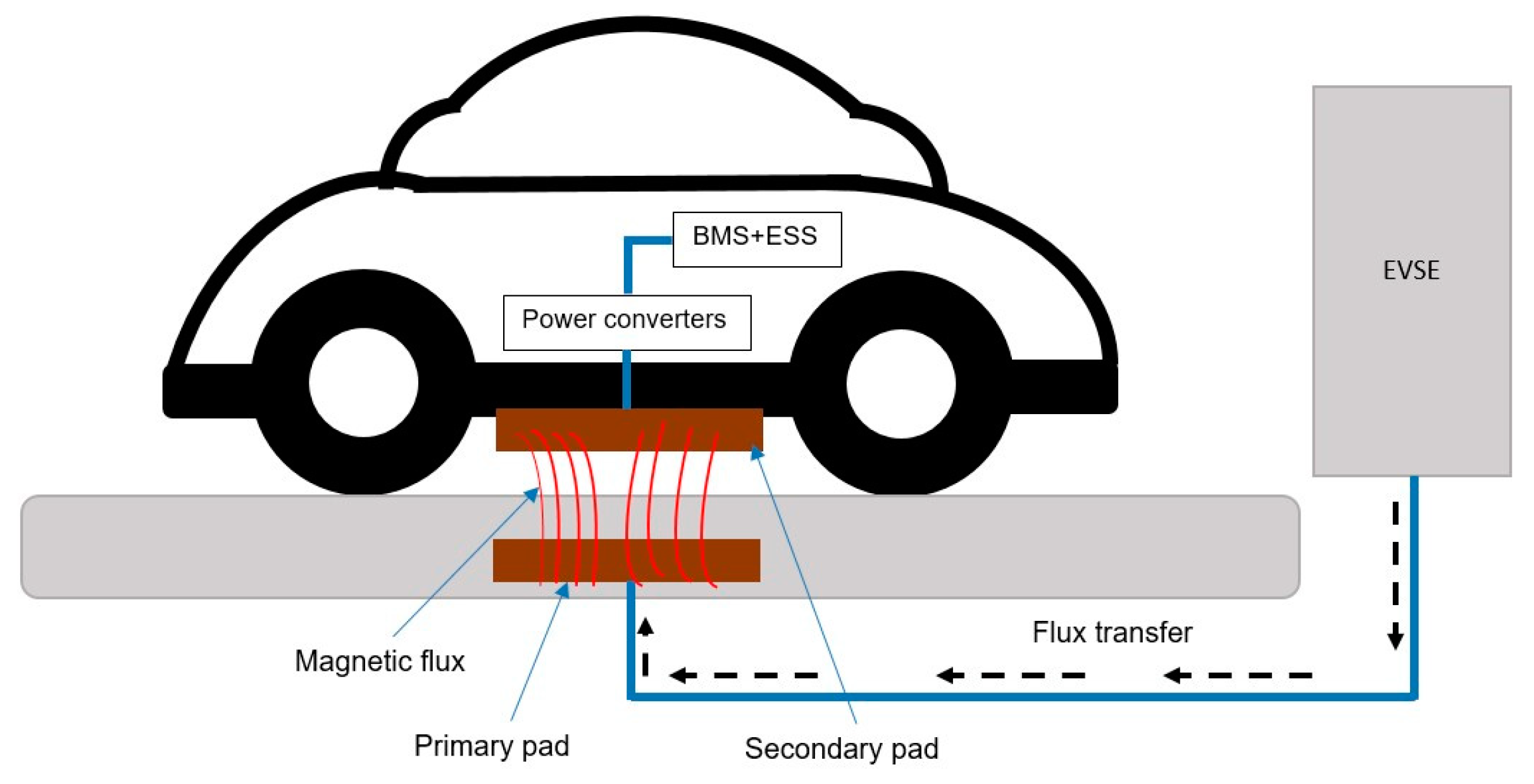
2. Design Methodology for WPT System

2.1. The Resonant WPT System for SS Topology

Electric vehicles can be wirelessly charged through three modes:
  • Static charging: this mode involves charging the vehicle at specific locations with the engine turned off, either at home or in charging stations.
  • Stationary charging: Vehicles can be charged in dedicated zones such as traffic lights while the engine of the vehicle is still running. This mode is particularly useful for public transportation, such as taxis and buses.
  • Dynamic charging: This mode involves charging the vehicle when it is in motion, and the road is equipped with electronics to facilitate the charging process.
This research focuses on the static charging mode, as depicted in Figure 1. The charging process in this mode consists of two parts:
  • The off-board part is situated on the ground outside the vehicle and spans from the Electric Vehicle Supply Equipment (EVSE) to the primary coil.
  • The on-board part is located within the vehicle and extends from the receiving coil into the battery of the vehicle.
Figure 2 presents the bidirectional WPT system model charging circuit. A bidirectional WPT system permits the transfer of energy in both directions which provides the charge and discharge of the electric vehicle. This system presents an optimal solution for the environment by providing backup for renewable power sources.
The reason for selecting the serial–serial compensation topology in this circuit is that the capacitance values can be determined using Equations (4) and (5) without being affected by load resistance (RL) and the mutual inductance (M).
The initial step in the charging process involves converting the utility AC power to adjustable DC power, using an AC–DC rectifier that has a power factor correction. Subsequently, a full-bridge inverter is utilized to convert the DC power to high-frequency AC power, which powers both the primary coil and the compensation network. The voltage induced in the second part is then rectified by the secondary rectifier, which charges the battery of the vehicle.
In WPT applications, high powers, and high switching frequencies are required. To this end, the Sic-MOSFET presents the optimal solution in WPT chargers [17].
Figure 3 shows the equivalent circuit model for SS topology. Following Kirchhoff’s voltage law, the system can be expressed as follows:
[ V 1 0 ] = [ Z 1 j w M j w M Z 2 ] · [ I 1 I 2 ]
where Z 1 and Z 2 represent the impedance of both sides;
Z 1 = R 1 + j w L 1 + 1 j w C 1
Z 2 = R 2 + R L + j w L 2 + 1 j w C 2
Thus, the current phasor circulating in the first and second sides of I 1 and I 2 are expressed as
I 1 = V 1 · Z 2 ( w M ) 2 + Z 1 · Z 2
I 2 = j w M V 1 ( w M ) 2 + Z 1 · Z 2
The induced voltage created in the receiving coil V 2 , i n d u c e d and transmitting coil V 1 , i n d u c e d due to coupling between two coils are defined as
V 2 , i n d u c e d = j w M I 1
V 1 , i n d u c e d = j w M I 2
The expression of Z R e f , which represents the reflected impedance, can be defined as:
Z R e f = j w M I 2 I 1 = w 2 M 2 Z 2
Therefore, one can define the total equivalent impedance Z t o t that is observed from the primary side of the WPT system as
Z t o t = Z 1 + Z R e f Z t o t = Z 1 + w 2 M 2 Z 2
At the frequency of resonance of the system, one can represent the current of the first section and the efficiency of the power transfer, denoted as η, using the following expressions:
I 1 = V 1 · R 2 + R L ( w M ) 2 + R 1 R 2 + R L
η = P o u t P i n = R L I 2 2 V 1 I I = R L × ( w M ) 2 ( R 2 + R L ) × R 1 × R L + R 2 + ( w M ) 2

2.2. Calculation of the Design-Related Parameters

This study proposes the methodology to define the exact dimensions of the pad to transfer the power of 3.7 kW to the battery of the vehicle. The first step to follow is to define the initial parameters and calculate the electrical parameters.
The [18] standard mandates that the frequency of operation should fall within the range of 79.00 kHz to 90 kHz, with a target frequency of 85 kHz. As a result, the pulsation at the resonant frequency w r is
w r = 2 π f r

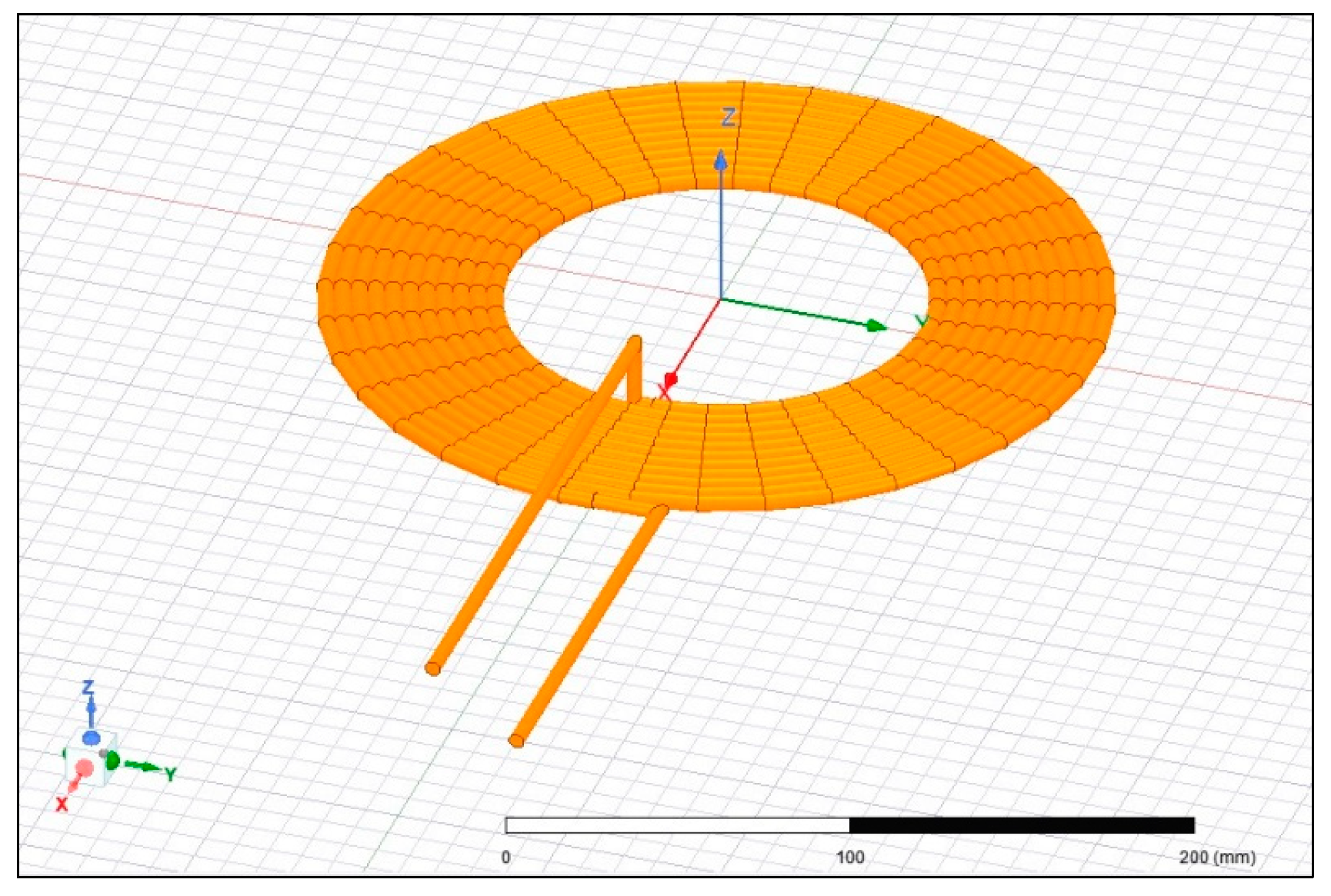
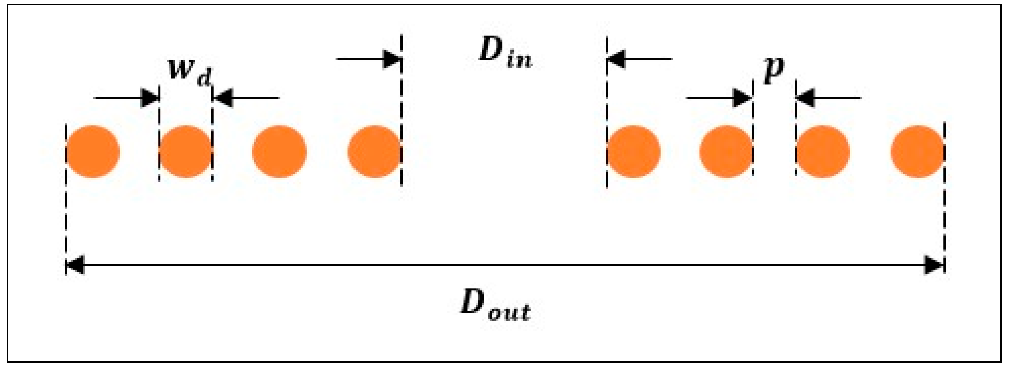
2.2.1. The Design Parameters of the Pad

Developing effective coils used to transfer and receive energy is a crucial exercise to reach high efficiency. The circular coil has a single-sided magnetic field that helps in reducing leakage flux [19].
To facilitate the analysis, both coils are made to possess identical dimensions.
The present study maintains a constant external diameter of the coil and focuses on optimizing the other three parameters; namely, the inner diameter, the number of turns in the coil, and the sections of the winding. This optimization is aimed at achieving the optimal design that can effectively transfer the desired power.
An illustration of the circular coil model is presented in Figure 4, which was generated by Ansys Maxwell.
The fundamental dimensional parameters comprise the number of turns, wire diameter, and spacing between adjacent wires, as well as the inner and outer diameter.
The thickness of the coil is determined by two factors:
  • The wire diameter w d , which is selected according to the current of the coil.
  • The pitch of the coil represents the height of one complete turn.
Besides these parameters, the design of ferrite and shielding also affects the pad design. The analysis of the latter is detailed in Section 3.
Figure 5 shows a flat circular coil in cross-section. Here, D i n is the inner diameter, D o u t is the outer diameter, w d is the wire diameter, and p is the spacing between the adjacent wires. The relationship between D i n and D o u t can be inferred from Figure 5 as follows [20]:
D o u t = D i n + 2 · w d + p + w d · ( 2 N p 1 )
The present investigation aims to minimize the value of p as much as possible. The expression for the inner diameter is given as:
D i n = D o u t 2 · w d N p w d
Thus, the winding sections are seen as identical for both the primary S p and secondary S s sections. For the circular shape, the winding section is expressed as:
S = S p = S s = π 4 · ( D o u t 2 D i n 2 )
The total length of the copper wire l l e n g t h , in meters, is given by [21]:
l l e n g t h = π · N · ( D i n + D o u t ) 200
Thus, the coil resistance can be described as:
R = ρ · l l e n g t h S c
where
ρ = 1.68 × 10 8   Ω · m refers to the resistivity of copper, and
S c = π 4 · w d 2 refers to the cross-sectional area of copper.
Furthermore, the vertical separation Z d i s t between the coils is an essential parameter to be considered for WPT specifications to ensure maximum power transfer. According to the SAE J2954 standard [18], three z-classes of the WPT system are defined based on the estimated ground clearance:
Z 1 = 100 150   m m
Z 2 = 140 210   m m
Z 3 = 170 250   m m
Therefore, the Z 1 category is opted for and the distance between the coils is roughly 120 mm. The height of the magnetic path of the circular coil is approximately a quarter of the coil’s diameter, which necessitates a larger coil to achieve a strong coupling.
Consequently, the outer diameter of the transmitting coil is equal to 480 mm.
As a result, the transmitting coil has an external diameter of 480 mm.
D o u t 4 · Z d i s t
The SAE J2954 standard [18] specifies that the transmitting pad package can be mounted in three ways: above the ground surface, flush with the ground surface, or buried, as illustrated in Figure 6. The standard recommends a maximum protrusion distance of 70 mm above the ground surface, but local installation rules may require a different value.
The three mounting methods are defined as follows:
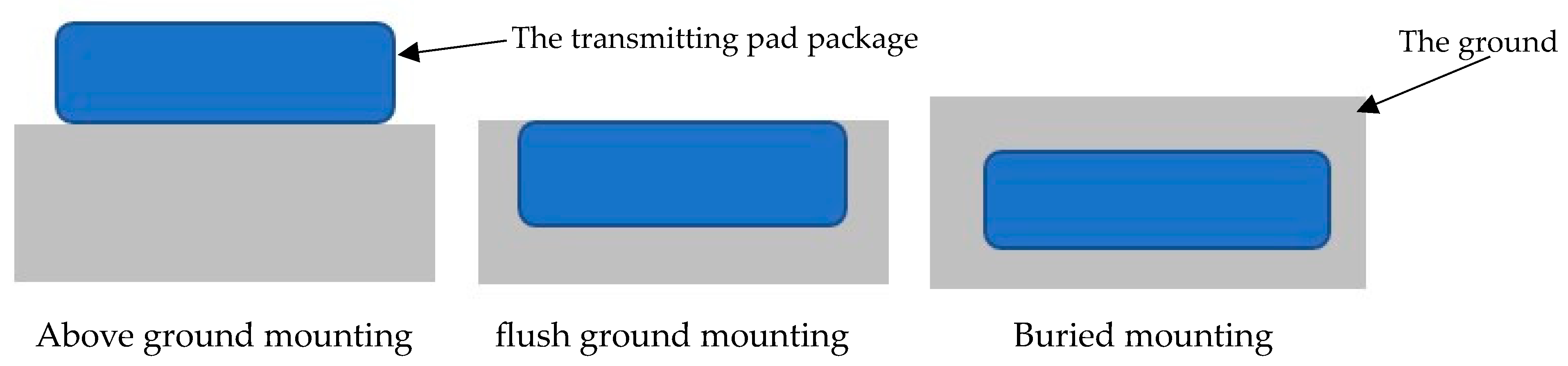
  • Above Ground Mounting involves mounting the pad assembly on the surface.
  • Flush Ground Mounting involves mounting the pad assembly within the surface, with the top of the pad flush with the surface.
  • Buried Mounting involves mounting the pad with the top of the pad below the surface.
In our particular case, the “Above Ground Mounting” option has been utilized.

2.2.2. The Electrical Parameters and the Transferred Power Expression

The second step to follow is to determine the electrical parameters. All measures are at the resonant frequency.
The capacitors required for the SS compensation topology can be determined using the following calculations [9,14]:
C 1 = 1 w 2 L 1 C 2 = 1 w 2 L 2
The quality factor of the receiving side is
Q 2 = w 0 L 2 R L + R S
Assuming the battery is connected directly to the rectifier, it is possible to express the equivalent resistance of the load as illustrated in Equation (22) [11]:
R b a t = V b a t 2 P b a t
R L = 8 π 2 · R b a t
Likewise, to deduce the optimal load for maximum transfer efficiency, the derivation of the expression of the efficiency (11) relative to the load is calculated as follows:
d η d R L = d R L × w M 2 R 2 + R L × R 1 × R L + R 2 + w M 2 d R L = 0 R 2 + R L ) · R 1 · R 2 + R L + w M 2 R L · 2 R 1 · R 2 + R L + w M 2 = 0 R L = R 2 · 1 + w M 2 R 1 R 2
The transmitted power P t r a n s of a WPT system can be expressed as [22,23]
P t r a n s = w 0 I 1 2 M 2 Q 2 L 2
In addition to (25), the transmitted power can be rewritten as
P t r a n s = w 0 2 I 1 2 M 2 R L

2.3. Magnetic Core and Shielding Plate: Analysis and Design

The objective of this section is to find the best combination of ferrite and aluminium necessary to reach high efficiency.

2.3.1. Magnetic Core

Ferrite materials possess several advantages over other materials when it comes to high frequencies, such as minimal eddy current losses, high electrical resistivity, low cost, and high stability [24]. The objective of adding ferrite to the coil is to constrain flux to the desired path and thereby increase the coupling value. The use of ferrite in such a system also helps to reduce the leakage of magnetic flux.
Several designs are reported in the literature such as pot core, U-shaped, or E-shaped designs. These configurations are fragile and expensive and therefore not suitable for electric vehicle applications [25]. The same applies to the ferrite plate.
To illustrate the foregoing, a simple analysis is performed using Ansys Maxwell software. Three models are designed as shown in Figure 7a–c. Figure 7b is characterized by the presence of eight ferrite bars. The form of ferrite in Figure 6c is a plate form (circular disc). The dimensions of ferrite are described in Table 1.
Table 2 displays the results of simulations conducted to assess the coupling coefficient under various scenarios, with vertical distances ranging from 100 mm to 200 mm for the following scenarios:
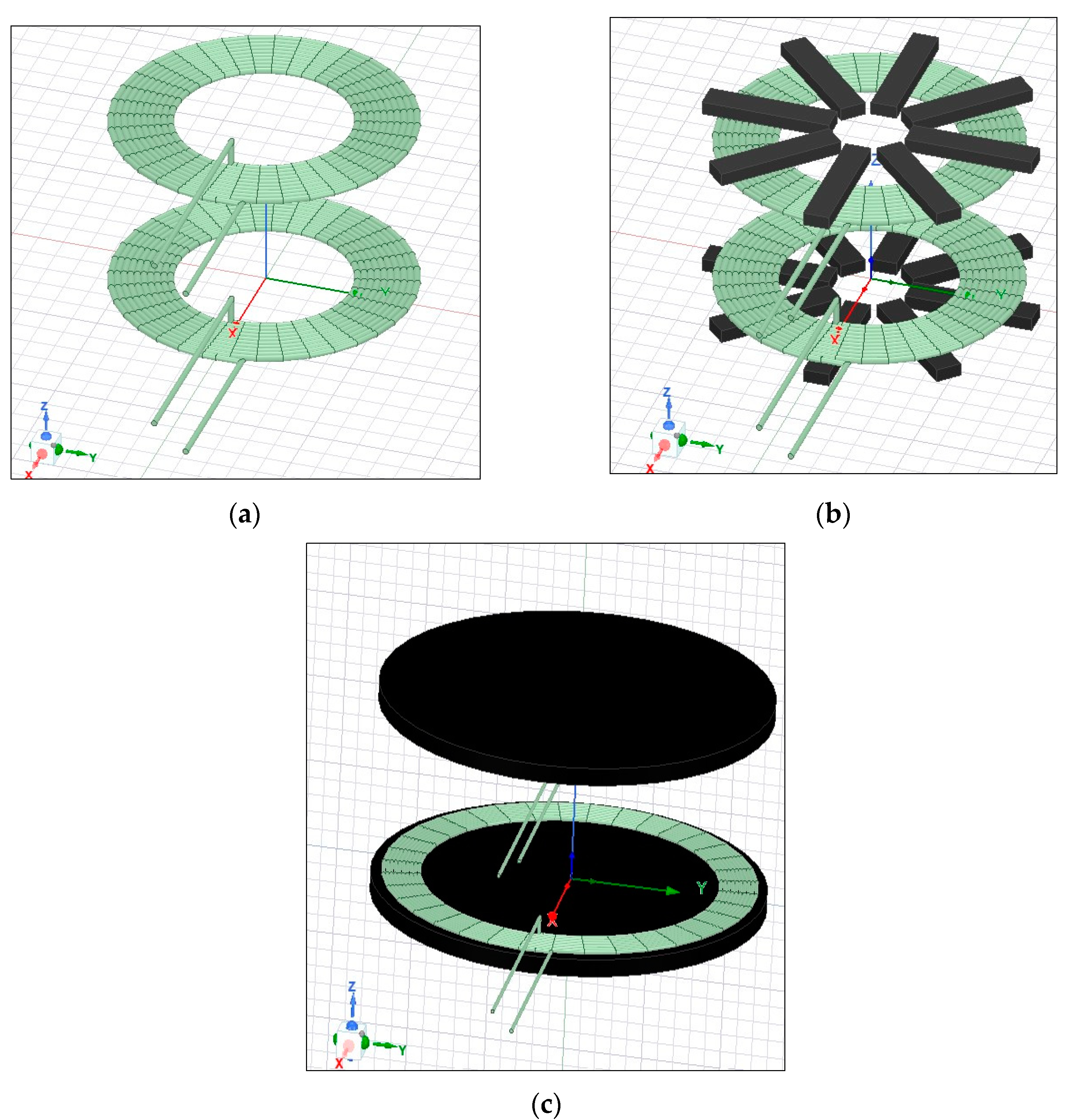
  • Scenario 1: circular coreless model.
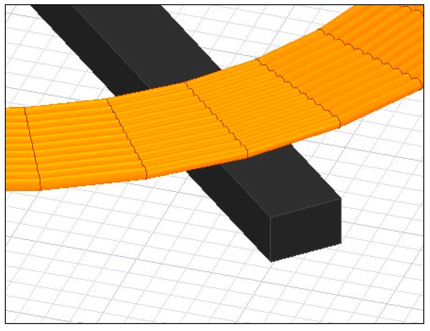
  • Scenario 2: circular core model using ferrite bars.
  • Scenario 3: circular core model using a ferrite plate.
The inclusion of the ferrite bars improves the coupling of the system by guiding the flux toward the secondary coil. Indeed, the ferrite bars (Scenario 2) provide an alternative path to the magnetic field lines; thus, this ensures better coupling compared to the coreless coil (Scenario 1).
An additional issue to consider is the decline in the value of the coupling with a large air gap indicating that the magnetic field lines may not be able to reach the receiving coil as the vertical distance increases.
A comparison of the coupling coefficients in Scenario 2 and Scenario 3 shows that using a magnetic ferrite plate results in a higher coupling coefficient than with ferrite bars. Adding more ferrite can also improve the coupling performance. However, the design complexity of the ferrite plate limits the possibility of its use. A solid piece of ferrite could make the pad heavier and more expensive.
Hence, ferrite bars are often utilized in the design of WPT systems to strike a balance between the weight of the pad and the coupling of the system.
In [26], multiple simulations were conducted at a fixed gap to determine the parameters that significantly impact the coupling. The results reveal that long and narrow ferrite blocks are the most effective for maximizing ferrite utilization. Long bars have the ability to provide a high flux path, leading to an increase in flux density above bars, whereas narrow bars allow flux around the coil, leading to more efficient guidance. In addition, ferrites should be centered on the coil.
The coupling reaches a higher value by increasing the thickness of ferrite bars. However, the ferrite thickness must take into consideration the pad weight and the density of magnetic flux to avoid ferrite saturation at maximum power. Additionally, a larger ferrite core relative to the coil can lead to a higher coupling, as illustrated in Figure 8 [25]. Therefore, the length of the ferrite bars must exceed the edge of the coil as depicted in Figure 8.

2.3.2. Shielding Plate

The shielding plates are used to reduce and confine the emissions of the magnetic field in the surrounding area. Typically, the primary and secondary coils are supplemented with aluminum plates. Aluminium metal is characterized by its high conductivity and high strength. Furthermore, the induced eddy current in this metal aid in preventing the leakage flux. Hence, the filed lines between coils are confined and the leakage flux to the surroundings is reduced [27].
A circular coil model with ferrite bars and an aluminum plate is depicted in Figure 9, where the aluminum plate measures 600 × 600 × 1 in size. The simulations are performed in the Ansys Maxwell environment.
Figure 10 illustrates the magnetic field distribution on a YZ plane for the following cases:
  • Case 1: circular coreless model (no shielding) as shown in Figure 6a.
  • Case 4: circular core model using ferrite bars and an aluminium plate as shown in Figure 8.
The use of aluminium in the model results in better shielding as it reduces the leakage flux in the surrounding region in comparison to the coreless model. Thus, the addition of aluminium limits the extension of the flux at the top and bottom of each pad.
One can also note that a high concentration of flux is located in the ferrite bars, which is represented in the figure by the red color.
Based on the results obtained in [25,28], the shielding effect is unaffected by the Al plate size. Thus, the large aluminium size causes a lower coupling.
The aluminium thickness must be appropriately designed and calculated. Achieving greater efficiency requires that the thickness of the aluminium plate is greater than the skin depth [29]. Thicker plates present advantages to the shielding but the pad weight will increase.
δ = ρ π f μ 0 μ r
where δ is the skin depth in m, f is the frequency in Hz, μ r is the relative magnetic permeability of the conductor in H/m, μ 0 is the permeability of free space, and ρ is the resistivity of the conductor in Ω-m.
To enhance the security of people around the vehicle, the magnetic flux should remain below the limit set by the ICNIRP guidelines for human safety [30].
In order to achieve the best possible shielding, it is essential to keep the dimensions of the aluminum plate larger than the ferrite bars length [28].
Based on the foregoing discussions, the number of ferrite bars equals eight for each coil. In addition, the length of the ferrite bars remains unchanged during the iterative algorithm since the outer diameter of the coil is fixed.
The dimensions of the ferrite and aluminium are detailed in Table 3.

2.4. Design Methodology for WPT System for SS Compensation Topology

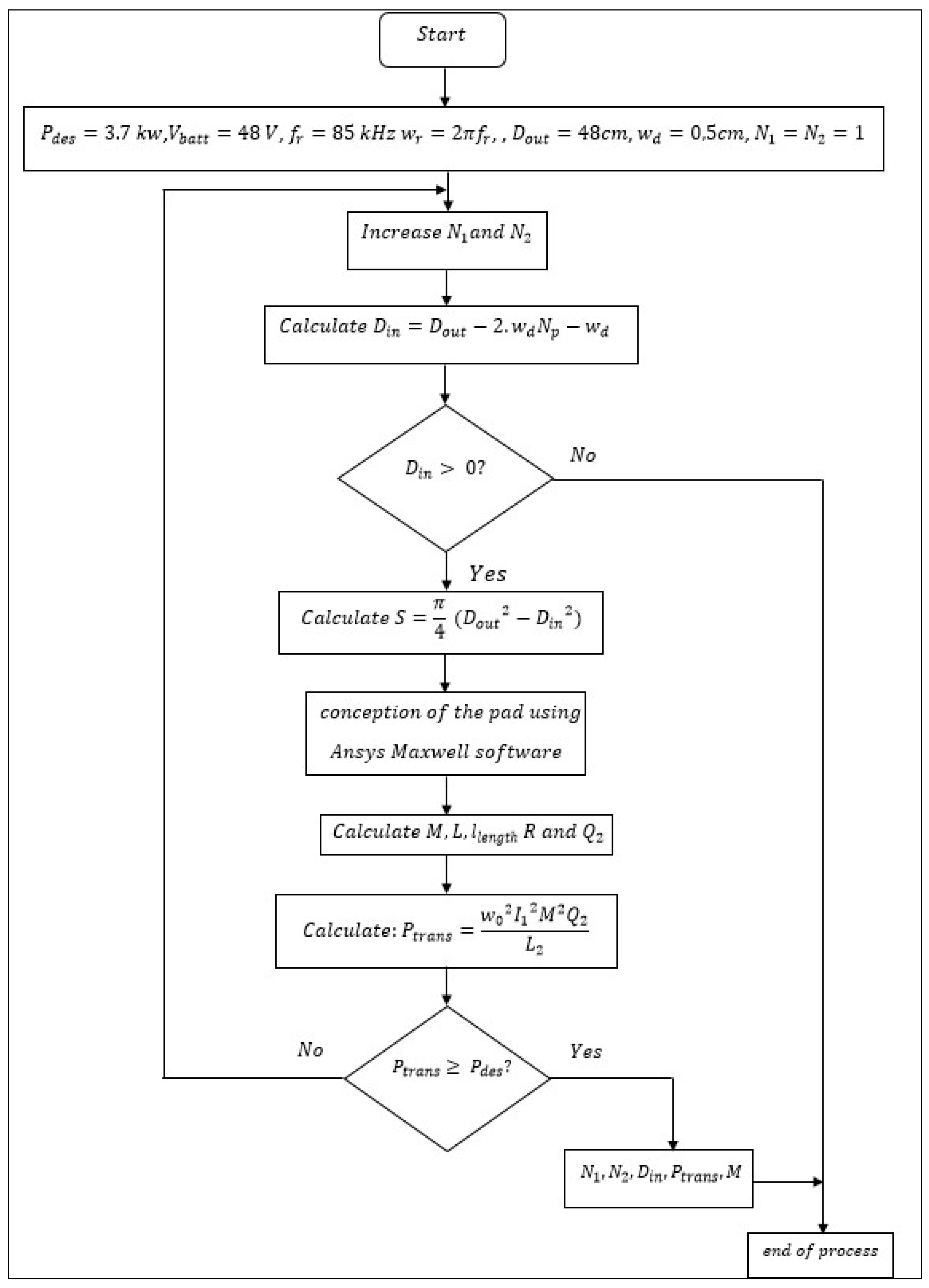
2.4.1. Flow Chart of Pad Dimension Optimization

In this section, a design methodology is developed for the serial–serial WPT system based. The objective is to determine the pad dimensions needed to transfer the power of 3.7 kW to the battery of the vehicle. The design process starts with the following initial parameters: the desired power to transfer P d e s , the battery voltage V b a t t , the primary excitation current I 1 , the wire diameter w d , and the external diameter of the primary coil D o u t . Afterward, the iterative optimization procedure is utilized until the desired power is achieved. Figure 11 depicts the flow chart of the design process. This design methodology is applicable to the various power levels of the WPT system. The value of the external diameter of the coil and the Litz-wire diameter are 48   c m and 0.5   c m , respectively. Thus, the number of turns and the inner diameter are variable parameters. The process is initiated by increasing the number of turns and calculating the inner diameter and the winding section using (8) and (9), respectively. Then, the mutual inductance and the secondary self-inductance and resistance are calculated using Ansys Maxwell for the given coil design. As such, the transferred power P t r a n s is calculated using (26), and if the value calculated is superior or equal to P d e s = 3.7 kW then the process will stop and the number of turns and the inner diameter are determined. Otherwise, the number of turns is incremented by 1. The algorithm continues until the calculated power is greater than or equal to the desired power of 3.7 kW. Then the process stops, and N 1 , N 2 , D i n ,   and   P d e s are determined.

2.4.2. The Results of Coil Dimensions and Design Parameters for a 3.7 kW WPT System

The design approach outlined in the previous section is employed for the series–series WPT system with an 85 kHz resonant frequency and a 120 mm vertical distance between the two coils.
Thus, the dimensions of the ferrite and aluminium plate are specified for use in the iterative algorithm. In addition, the inner diameter of the coils, the winding sections, and the number of turns are variable parameters that were eventually determined by the algorithm.
Table 4 presents the results of the processes for a diverse number of turns.
The final selection of parameters is based on the configuration that satisfies the following two conditions:
  • Minimizing the length of the cable (Equation (16)).
  • Verifying the bifurcation condition (Equation (35)).
The appropriate coil parameters given by the iterative algorithm to transfer 3.7 kW are reported in Table 5.

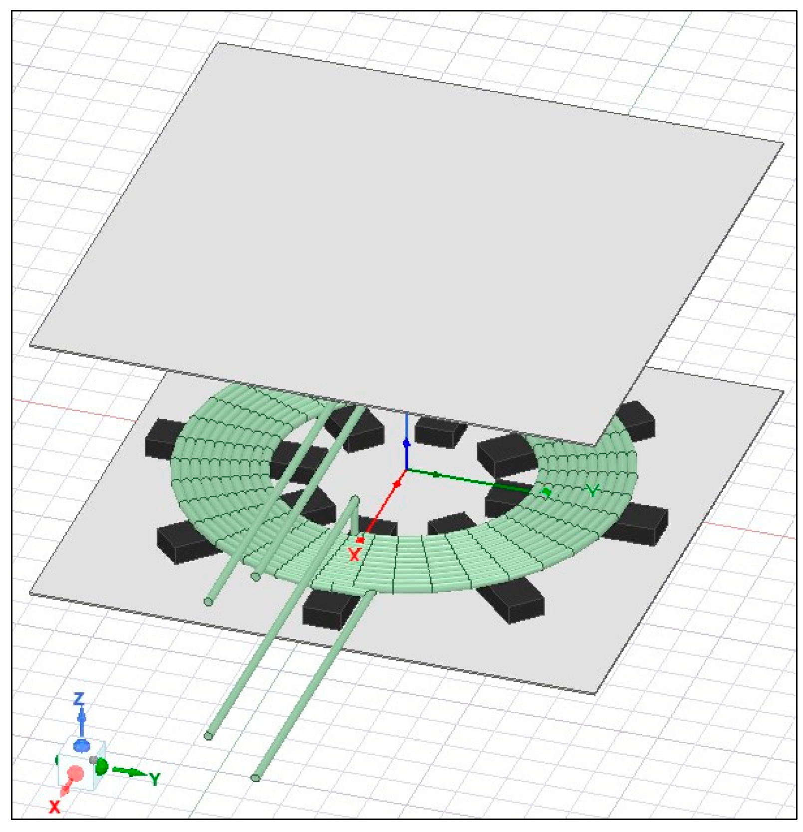
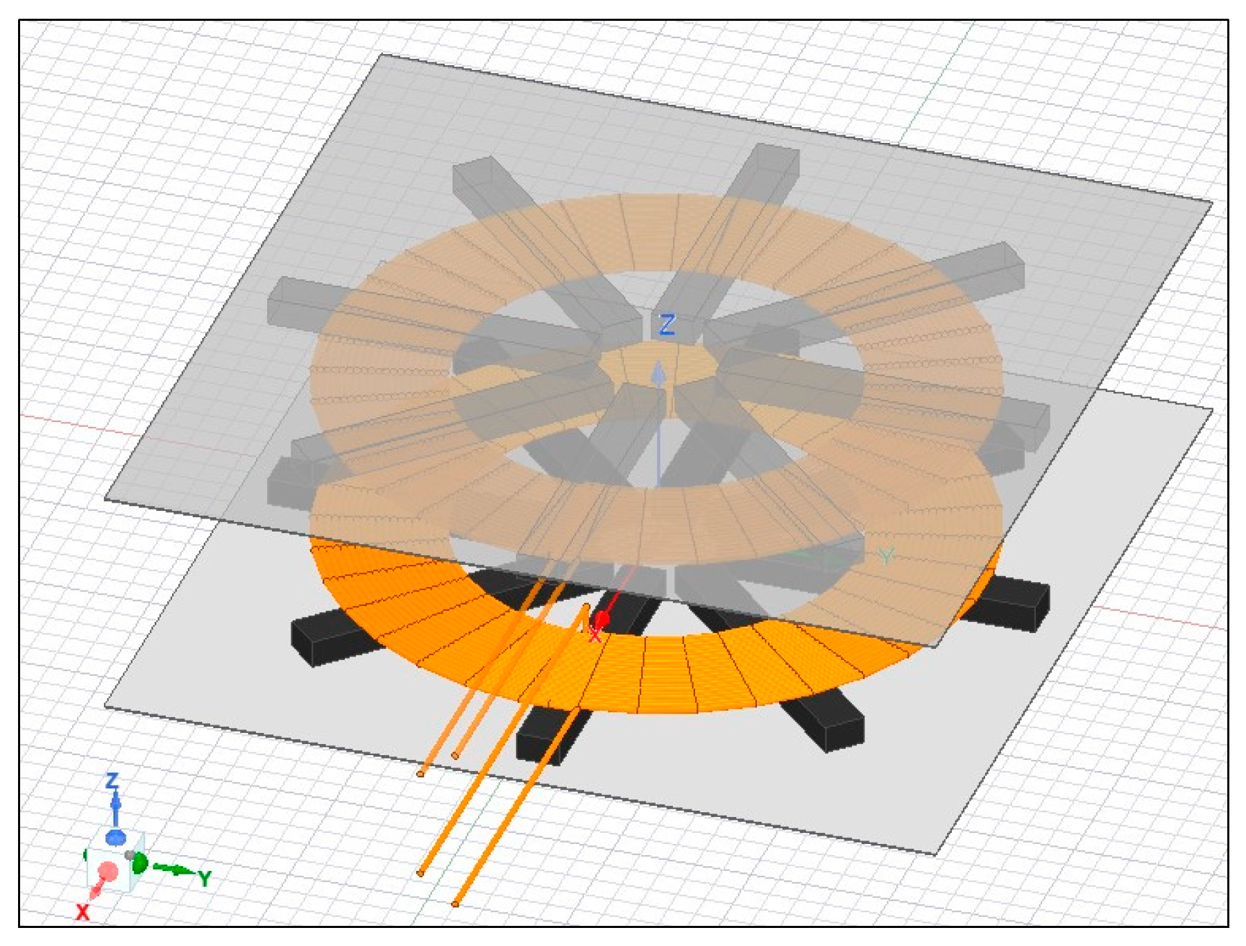
3. Verification and Analysis of the Magnetic Design

3.1. Finite Element Modeling

In this section, the pad is designed based on the results of the algorithm. The litz wire is used for winding the coils of the WPT system. This option is chosen to lower the wire resistance which increases at higher frequencies due to the skin effect and proximity effect. These effects are non-linearly frequency dependent and change the current density in the conductor. These effects can be mitigated by utilizing a parallel multi-strand litz-wire winding [31]. The litz wire is composed of many insulated parallel strands in a bundle.
Table 6 describes the characteristics of the litz wire used for modeling the coil.
The ferrite Mn–Zn PC95 and the litz wire are modeled in Ansys Maxwell using the eddy current analysis solution. Figure 12 depicts the final pad design based on the results in Table 6.

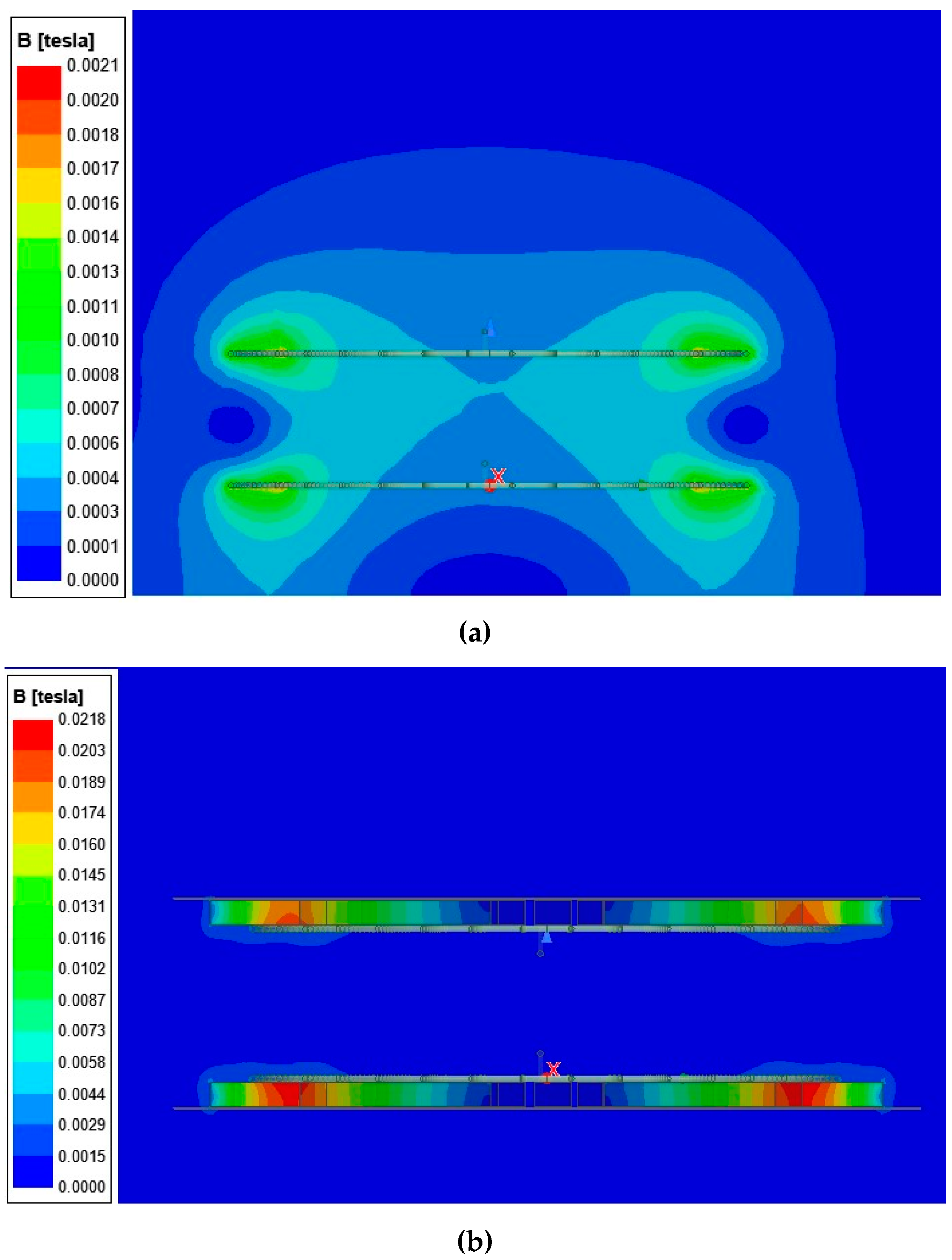
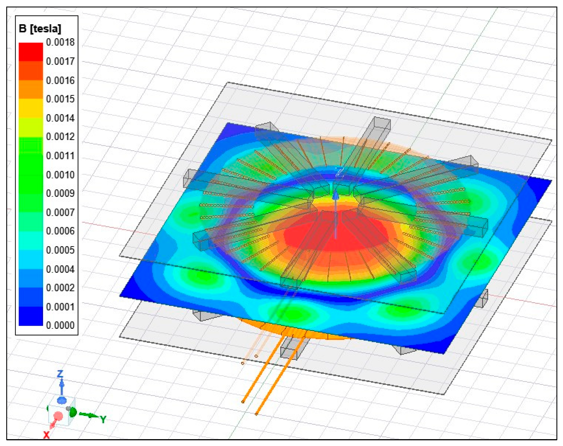
3.2. The Distribution of Magnetic Flux Density

The magnetic flux density distribution across the two pads is shown in Figure 13.
The scale in the figure indicates the lowest and highest value presented by the blue and red colors, respectively.
An XY direction sheet illustrates the magnetic flux distribution. The results validate the interaction between the primary and secondary coils.
The strongest flux density is observed in the middle of the sheet, which means that the dangerous field area is located and concentrated in the middle. Similarly, the intensity decreases further away from the center of the coil.
It is worth noting that the number and shape of the ferrite affect the mutual inductance between the two coils.
That is why the results may differ depending on existing materials. In the simulation case, we opted for the best combination of pad components.

3.3. Types of Losses of the Magnetic Coupler

The losses in the WPT system regroup the totality of the losses produced by all the components, especially those that constitute the magnetic coupler. These losses also cause a temperature rise. The type of losses commonly encountered in the WPT system are presented as follows:

3.3.1. Losses of the Litz Wire Coil

The losses in the coil create an increase in the temperature and include the ohmic loss and the eddy current loss associated with the skin and proximity effect.
The ohmic loss in the coil winding can be expressed as [6]:
P o h m i c = j 2 ρ d V = j 2 ρ A l = I 2 ρ l A = I 2 R
where l is the length of the wire, V is the volume of the wire, ρ is the resistivity of the medium of the wire, R the resistance of the entire wire, A is the surface area of the cross-section of the wire, and I is the current circulating in the wire.
Thus, the reduction of the current value or the AC resistance leads to a diminution in the ohmic loss of the coil.
The eddy currents’ effects are caused by two phenomena: the skin effect and the proximity effect.
The skin effect is a phenomenon in which the AC current flowing in the conductor tends to concentrate near the surface, resulting in a decrease in the effective cross-sectional area of the cable. Additionally, the proximity effect is due to the interaction of the magnetic field between adjacent conductors carrying currents [9,32].
The coil losses caused by the skin and the proximity effects can be defined as:
P s k i n & p r o x = ( F s k i n + F p r o x ) i r m s 2 r d c
where F s k i n and F p r o x indicate the loss factors of the skin and proximity effects, respectively; r d c is the DC resistance of the coil, and i r m s is the RMS current of the coil.
The factors F s k i n and F p r o x depend on the operating frequency, the magnetic field generated, and the form of the litz wire used [7,31].
Thereby, the losses of the coil can be expressed as:
P t o t = P o h m i c + P s k i n & p r o x

3.3.2. Losses of the Ferrite Core

The loss density in the ferrite core can be represented based on the Steinmetz equation [7]:
p c = k s f α B ^ β
where P c is the core loss per unit volume, B ^ is the peak flux density, f is the operating frequency, and k s , α and β are Steinmetz empirical constants.
Practically, 1 < α < 3; 2 < β < 3.
By integrating (31) over the volume of the core, the total loss is expressed as:
P c = k s f α B ^ β d V c
Here, V c refers to the volume of the ferrite.
Therefore, to reduce the core loss, the design must aim to minimize the quantity of magnetic flux density along with the operating frequency.

3.3.3. Losses of Aluminum Shield

As discussed in the preceding section, the shielding in the WPT system employs a conductive material with high conductivity. Typically, an aluminum plate is preferred to minimize the leakage flux produced.
Certainly, the magnetic flux created can only permeate a short distance into the shielding plate. To the exterior surfaces of the aluminum plate, an Impedance Boundary Condition (IBC) can be implemented in the FEA software because the skin depth is considerably smaller than the size of the aluminum.
The surface loss density on the shielding plates can be calculated as [33]:
p s = w μ 2 σ H t r m s 2
where H t r m s 2 is the RMS tangential magnetic field at the surface.
By integrating (33) over the surface of the shield, the total shielding plate losses are expressed as follows:
P s = w μ 2 σ H t r m s 2 d S
where S is the surface of the shield.

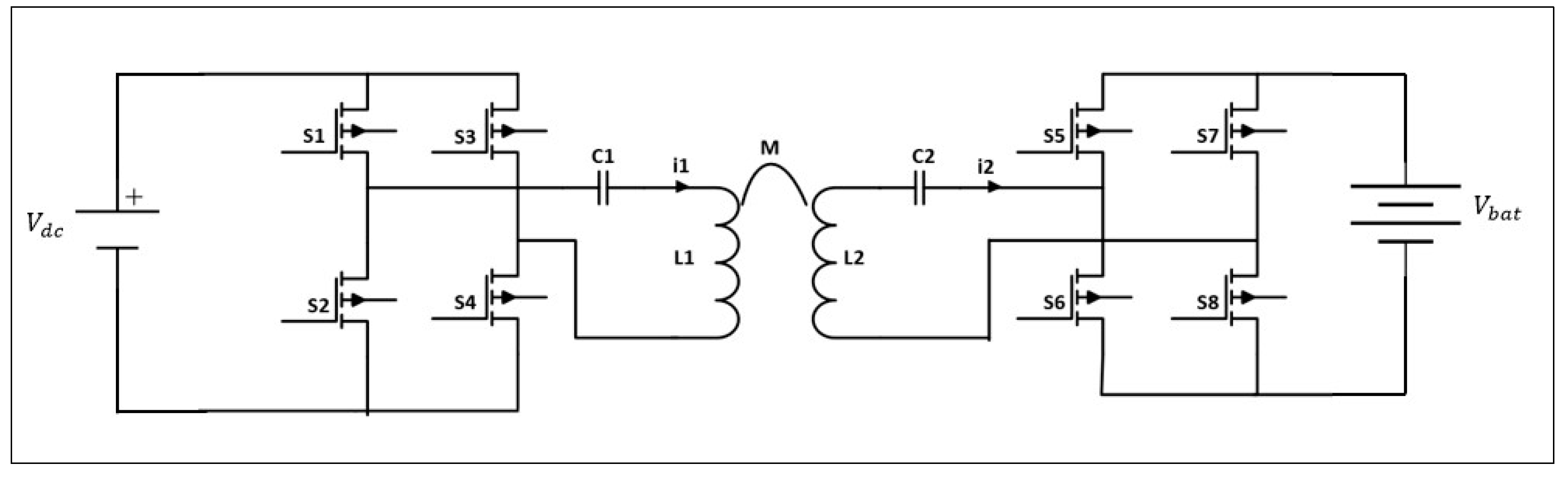
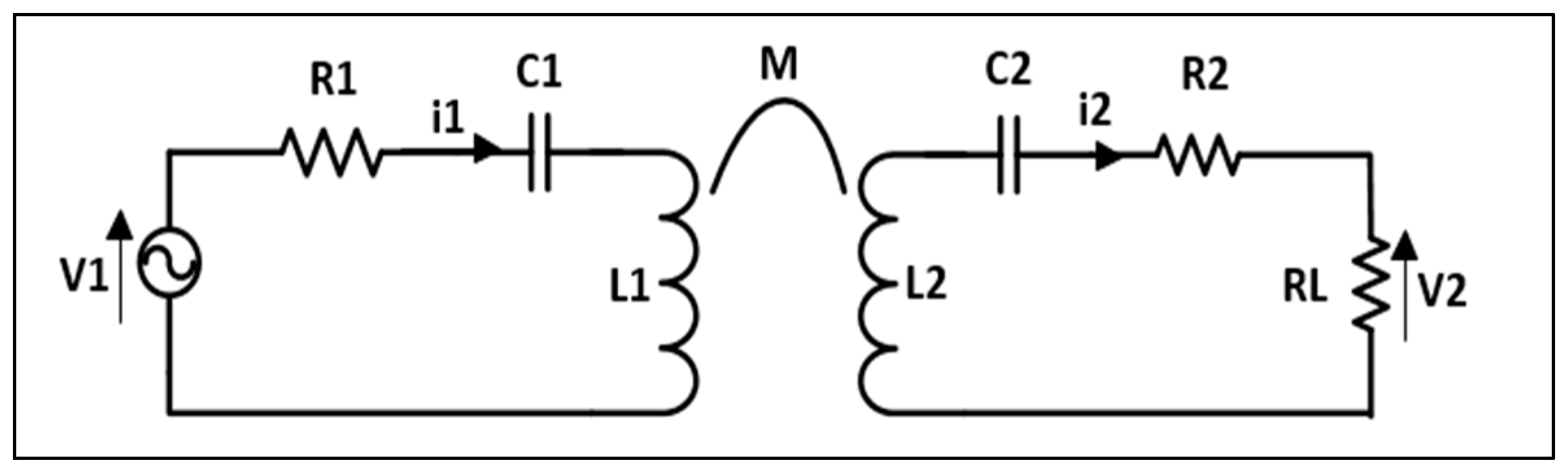
4. Circuit Analysis of the WPT System

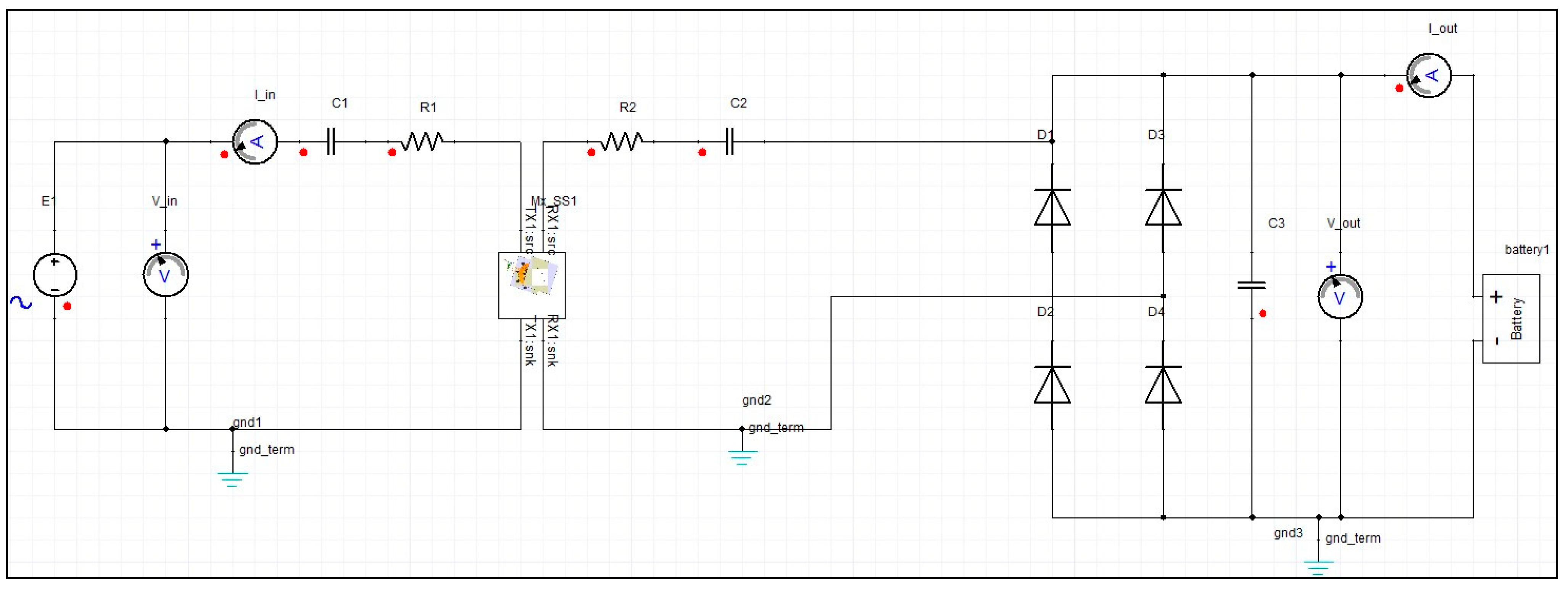
4.1. Presentation of the Simulation Circuit

This section constitutes an analysis of the circuitry for the unidirectional WPT system. The circuit model has been simplified, and the primary section of the circuit is supplied with an alternative source voltage. Furthermore, a diode full-bridge rectifier along with a capacitive filter Cf is used to convert the high-frequency voltage into DC voltage necessary for battery charging.
To decrease the leakage inductance and improve the coupling between the coils, capacitors used for compensation are included on both sides in series with the inductors.
The modeling and circuit analysis are carried out using the Ansys Simplorer environment. The circuit model design at a frequency of 85 kHz is obtained using the eddy current solution type.
On the other hand, the Maxwell 3D model previously designed in Section 2 following the design methodology is imported into ANSYS Simplorer to perform the co-simulation of the WPT system.
The electrical circuit of the simulated system, created with Ansys Simplorer, is illustrated in Figure 14. The model assumes a sinusoidal source as the input voltage source.
The capacitance and resistance values utilized in the circuit are determined by using Equations (20) and (17), respectively. Additionally, the nominal voltage of the battery pack is about 48 V.

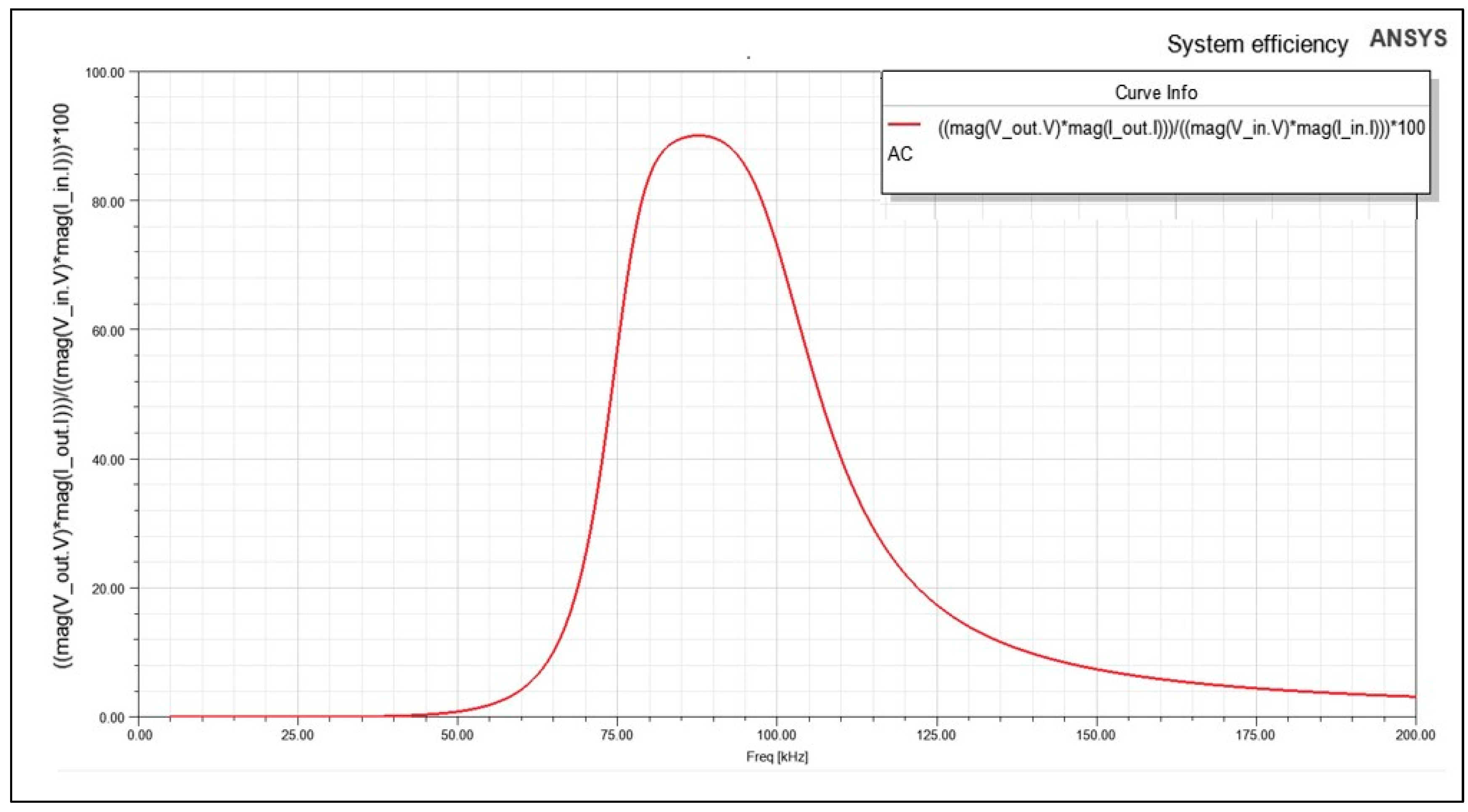
4.2. Simulation Results for 3.7 kW

Once the parameters of the system have been established, ANSYS Maxwell is employed to simulate the WPT system using the calculated parameters. Subsequently, co-simulation is then carried out using electrical circuits created in ANSYS Simplorer.
The accurate design of intricate systems for wireless charging was made possible with these two software programs.
The efficiency of the WPT system refers to the ratio of received power to transmitted power at a given frequency, and it is affected by several factors such as the coupling coefficient, variations in the load, and the main parameters of the coil.
Figure 15 illustrates the efficiency of the system previously designed (Figure 12) with the following characteristics:
  • Number of turns = 19.
  • Mutual inductance = 74.8 µ H .
  • Dimensions of ferrite bars = 230 (mm) × 30 (mm) × 20 (mm).
  • Dimensions of the aluminium plate = 600 (mm) × 600 (mm) × 1 (mm).
The simulations cover the frequency range from 5 kHz to 200 kHz. The results demonstrate that the specified dimensions enable the system to attain a high efficiency of up to 90.02%. These results are consistent with the analysis presented in Section 2. The proposed approach is anticipated to streamline the process of designing charging pads for use in wireless chargers with various power levels.

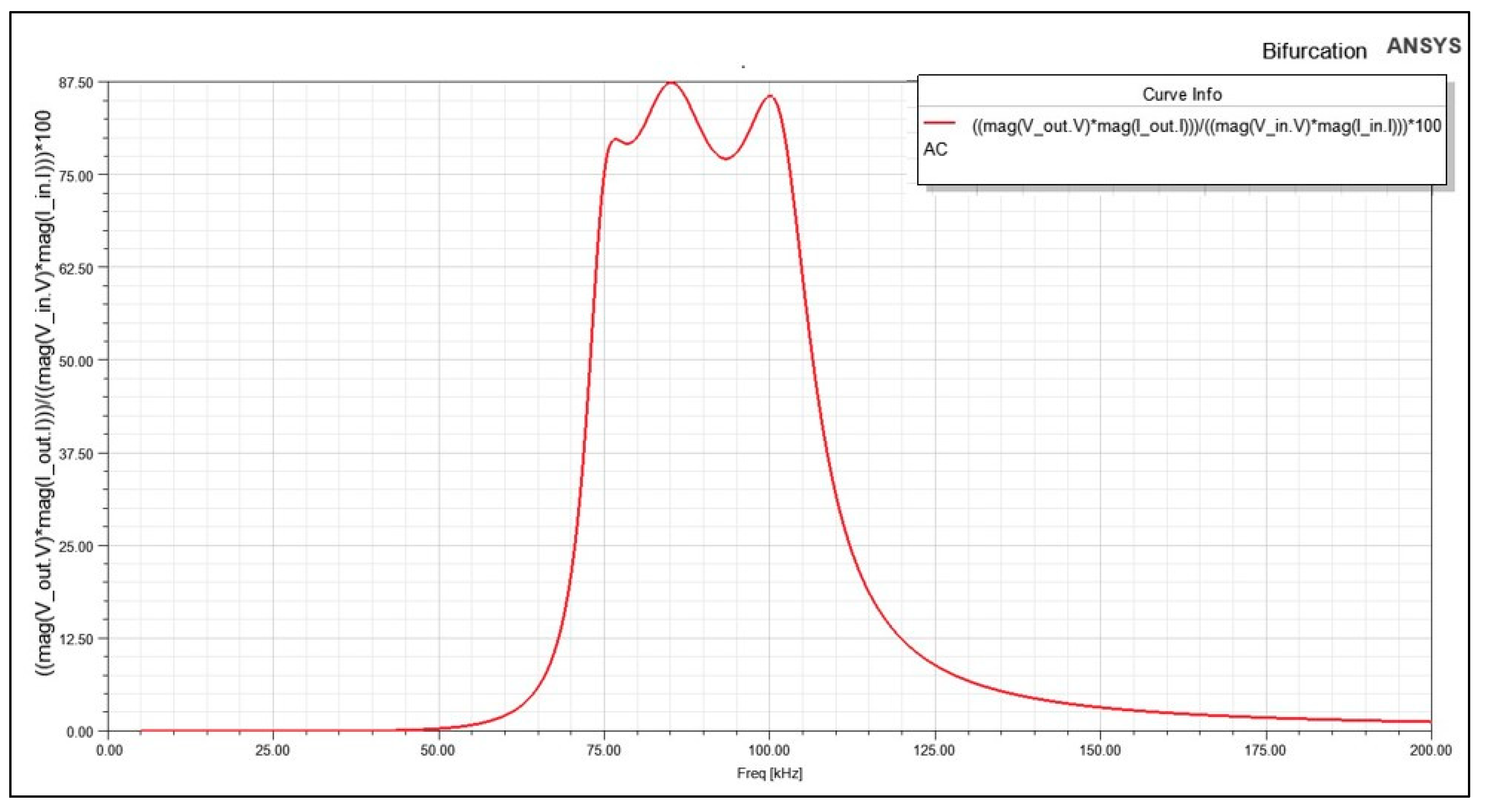
4.3. Bifurcation Phenomenon in WPT System

The resonant wireless power transfer (WPT) system is a dual-tuned circuit that utilizes compensation capacitors to achieve resonance with inductances of coils at the resonant frequency. The system may have multiple zero phase angle (ZPA) frequencies, which means that the curve changes from a single peak curve to multiple peak curves [34].
This phenomenon is called bifurcation. The latter occurs when the coupling coefficient exceeds a certain critical value called the splitting coupling factor kc.
According to [20], the coupling coefficient should be less than kc to avoid the bifurcation phenomenon. This refers to when
k < k c = 1 Q s 1 1 4 Q s 2
where Qs refers to the secondary quality factor.
The coupling coefficient of the system should respect kc to avoid bifurcation and to ensure an effective and stable operation of the system.
If the condition specified in Equation (35) is not fulfilled, the curve in Figure 15 will experience be modified.
Hence, to gain a better understanding of the bifurcation phenomenon, Figure 16 shows the results of efficiency vs. frequency for k k c .
The simulation shows the existence of three distinct peaks for values of k superior to kc; there is more than one maximum frequency. The bifurcation phenomenon depends on the compensation technologies, the reactive components, and the load value. In addition, the peak values could cause damage to the electronics in the wireless charger, hence the importance of studying the phenomenon to achieve optimal transfer [35].
As a result, it can be stated that to achieve a higher gain and consequently, a greater power transfer, the coupling needs to be lower than the critical coupling value.

5. Conclusions

The literature extensively discusses the magnetic resonant wireless system, but determining the optimal pad parameters for efficient power transfer remains a significant challenge. This paper presents a design approach for a series–series WPT system to transfer 3.7 kW power at a frequency of 85 kHz, which can be applied to various power levels. The magnetic design developed through this approach is analyzed and simulated. The simulation results reveal that the system can achieve high efficiency of up to 90.02% while preventing the occurrence of the bifurcation phenomenon.
The main contributions of this work suggest an accurate sizing technique for pads to transfer a given power. The proposed approach involves a comprehensive analysis that covers various aspects, including:
  • The importance of ferrite and aluminum in the system.
  • The exact dimensions of the ferrite and aluminum plate bars.
  • A clear methodology based on FEA software that provides optimized pad dimensions such as the length of the litz wire needed for coil construction, the outer diameter Dout, the inner diameter Din, and the number of turns N.
  • The study incorporates a circuit analysis to confirm the identified dimensions and enhance the efficiency of the system.
Therefore, the pad design represents a decisive part of the complete definition of the charging operation of electric vehicles.
Future work will discuss the safety issue of humans exposed to the magnetic field during the operation of charging the electric vehicle in depth.

Author Contributions

This paper was developed by a research team from an ASE Laboratory; conceptualization, methodology, and formal analysis, T.B. and H.E.F.; software, T.B., I.B. and A.L.; investigation and resources, T.B., A.L., M.K., and S.E.J.; writing, T.B. and I.B; review and supervision, M.K. and H.E.F.; Data curation, S.E.J. All authors have read and agreed to the published version of the manuscript.

Funding

This research was funded by the Research Institute in Solar Energy and New Energies (IRESEN), grant number: INNO-PROJECT 2018/CBSCVEV2X.

Acknowledgments

The authors express their gratitude for the support provided by the Moroccan research institute for Solar Energy and New Energies (IRESEN) through the grant ‘INNO-PROJECT 2018/CBSCVEV2X’.

Conflicts of Interest

The authors declare no conflict of interest.

References

  1. Hwang, Y.J.; Kim, J.M. A Double Helix Flux Pipe-Based Inductive Link for Wireless Charging of Electric Vehicles. World Electr. Veh. J. 2020, 11, 33. [Google Scholar] [CrossRef]
  2. Olukotun, B.; Partridge, J.; Bucknall, R. Finite Element Modeling and Analysis of High Power, Low-Loss Flux-Pipe Resonant Coils for Static Bidirectional Wireless Power Transfer. Energies 2019, 12, 3534. [Google Scholar] [CrossRef]
  3. Zhang, X.; Zhu, C.; Song, H. Wireless Power Transfer Technologies for Electric Vehicles; Key Technologies on New Energy Vehicles; Springer Nature: Singapore, 2022; ISBN 9789811683473. [Google Scholar] [CrossRef]
  4. Bouanou, T.; El Fadil, H.; Lassioui, A.; Assaddiki, O.; Njili, S. Analysis of Coil Parameters and Comparison of Circular, Rectangular, and Hexagonal Coils Used in WPT System for Electric Vehicle Charging. World Electr. Veh. J. 2021, 12, 45. [Google Scholar] [CrossRef]
  5. Bouanou, T.; Fadil, H.E.; Lassioui, A. Analysis and Design of Circular Coil Transformer in a Wireless Power Transfer System for Electric Vehicle Charging Application. In Proceedings of the 2020 International Conference on Electrical and Information Technologies (ICEIT), Rabat, Morocco, 4–7 March 2020; pp. 1–6. [Google Scholar] [CrossRef]
  6. Alsayegh, M.; Saifo, M.; Clemens, M.; Schmuelling, B. Magnetic and Thermal Coupled Field Analysis of Wireless Charging Systems for Electric Vehicles. IEEE Trans. Magn. 2019, 55, 1–4. [Google Scholar] [CrossRef]
  7. Liang, C.; Yang, G.; Yuan, F.; Huang, X.; Sun, Y.; Li, J.; Song, K. Modeling and Analysis of Thermal Characteristics of Magnetic Coupler for Wireless Electric Vehicle Charging System. IEEE Access 2020, 8, 173177–173185. [Google Scholar] [CrossRef]
  8. Vaka, R.; Keshri, R.K. Design Considerations for Enhanced Coupling Coefficient and Misalignment Tolerance Using Asymmetrical Circular Coils for WPT System. Arab. J. Sci. Eng. 2019, 44, 1949–1959. [Google Scholar] [CrossRef]
  9. Triviño-Cabrera, A.; González-González, J.M.; Aguado, J.A. Wireless Power Transfer for Electric Vehicles: Foundations and Design Approach; Power Systems; Springer International Publishing: Cham, Switzerland, 2020; ISBN 978-3-030-26705-6. [Google Scholar] [CrossRef]
  10. Ahmad, A.; Alam, M.S.; Mohamed, A.A.S. Design and Interoperability Analysis of Quadruple Pad Structure for Electric Vehicle Wireless Charging Application. IEEE Trans. Transp. Electrif. 2019, 5, 934–945. [Google Scholar] [CrossRef]
  11. Yang, Y.; El Baghdadi, M.; Lan, Y.; Benomar, Y.; Van Mierlo, J.; Hegazy, O. Design Methodology, Modeling, and Comparative Study of Wireless Power Transfer Systems for Electric Vehicles. Energies 2018, 11, 1716. [Google Scholar] [CrossRef]
  12. Kalwar, K.A.; Aamir, M.; Mekhilef, S. A Design Method for Developing a High Misalignment Tolerant Wireless Charging System for Electric Vehicles. Measurement 2018, 118, 237–245. [Google Scholar] [CrossRef]
  13. Yang, Y.; Cui, J.; Cui, X. Design and Analysis of Magnetic Coils for Optimizing the Coupling Coefficient in an Electric Vehicle Wireless Power Transfer System. Energies 2020, 13, 4143. [Google Scholar] [CrossRef]
  14. Sallan, J.; Villa, J.L.; Llombart, A.; Sanz, J.F. Optimal Design of ICPT Systems Applied to Electric Vehicle Battery Charge. IEEE Trans. Ind. Electron. 2009, 56, 2140–2149. [Google Scholar] [CrossRef]
  15. Siroos, A.; Sedighizadeh, M.; Afjei, E.; Sheikhi Fini, A.; Yarkarami, S. System Identification and Control Design of a Wireless Charging Transfer System with Double-Sided LCC Converter. Arab. J. Sci. Eng. 2021, 46, 9735–9751. [Google Scholar] [CrossRef]
  16. Kim, H.; Song, C.; Kim, D.-H.; Jung, D.H.; Kim, I.-M.; Kim, Y.-I.; Kim, J.; Ahn, S.; Kim, J. Coil Design and Measurements of Automotive Magnetic Resonant Wireless Charging System for High-Efficiency and Low Magnetic Field Leakage. IEEE Trans. Microw. Theory Tech. 2016, 64, 383–400. [Google Scholar] [CrossRef]
  17. Lassioui, A.; Fadil, H.E.; Rachid, A.; El-Idrissi, Z.; Bouanou, T.; Belhaj, F.Z.; Giri, F. Modelling and Sliding Mode Control of a Wireless Power Transfer System for BEV Charger. Int. J. Model. Identif. Control 2020, 34, 171–186. [Google Scholar] [CrossRef]
  18. J2954 (WIP) Wireless Power Transfer for Light-Duty Plug-In/Electric Vehicles and Alignment Methodology—SAE International. Available online: https://www.sae.org/standards/content/j2954/ (accessed on 7 September 2020).
  19. Patil, D.; McDonough, M.K.; Miller, J.M.; Fahimi, B.; Balsara, P.T. Wireless Power Transfer for Vehicular Applications: Overview and Challenges. IEEE Trans. Transp. Electrif. 2018, 4, 3–37. [Google Scholar] [CrossRef]
  20. Aditya, K. Design and Implementation of an Inductive Power Transfer System for Wireless Charging of Future Electric Transportation. Ph.D. Dissertation, University of Ontario Institute of Technology, Oshawa, ON, Canada, 2016. [Google Scholar]
  21. Bentalhik, I.; Lassioui, A.; EL Fadil, H.; Bouanou, T.; Rachid, A.; EL Idrissi, Z.; Hamed, A.M. Analysis, Design and Realization of a Wireless Power Transfer Charger for Electric Vehicles: Theoretical Approach and Experimental Results. World Electr. Veh. J. 2022, 13, 121. [Google Scholar] [CrossRef]
  22. Onar, O.C.; Chinthavali, M.; Campbell, S.L.; Seiber, L.E.; White, C.P.; Galigekere, V.P. Modeling, Simulation, and Experimental Verification of a 20-KW Series-Series Wireless Power Transfer System for a Toyota RAV4 Electric Vehicle. In Proceedings of the 2018 IEEE Transportation Electrification Conference and Expo (ITEC), Long Beach, CA, USA, 13–15 June 2018; pp. 874–880. [Google Scholar] [CrossRef]
  23. Covic, G.A.; Boys, J.T. Inductive Power Transfer. Proc. IEEE 2013, 101, 1276–1289. [Google Scholar] [CrossRef]
  24. Mude, K.N. Wireless Power Transfer for Electric Vehicle. Doctoral Dissertation, University of Padova, Padova, Italy, 2015. [Google Scholar]
  25. Zhang, W.; White, J.C.; Abraham, A.M.; Mi, C.C. Loosely Coupled Transformer Structure and Interoperability Study for EV Wireless Charging Systems. IEEE Trans. Power Electron. 2015, 30, 6356–6367. [Google Scholar] [CrossRef]
  26. Budhia, M.; Covic, G.A.; Boys, J.T. Design and Optimization of Circular Magnetic Structures for Lumped Inductive Power Transfer Systems. IEEE Trans. Power Electron. 2011, 26, 3096–3108. [Google Scholar] [CrossRef]
  27. Jiao, C.; Xu, Y.; Li, X.; Zhang, X.; Zhao, Z.; Pang, C. Electromagnetic Shielding Techniques in the Wireless Power Transfer System for Charging Inspection Robot Application. Int. J. Antennas Propag. 2021, 2021, 9984595. [Google Scholar] [CrossRef]
  28. Cui, H.; Zhong, W.; Li, H.; He, F.; Chen, M.; Xu, D. A Study on the Shielding for Wireless Charging Systems of Electric Vehicles. In Proceedings of the 2018 IEEE Applied Power Electronics Conference and Exposition (APEC), San Antonio, TX, USA, 4–8 March 2018; pp. 1336–1343. [Google Scholar] [CrossRef]
  29. Kim, H.; Cho, J.; Ahn, S.; Kim, J.; Kim, J. Suppression of Leakage Magnetic Field from a Wireless Power Transfer System Using Ferrimagnetic Material and Metallic Shielding. In Proceedings of the 2012 IEEE International Symposium on Electromagnetic Compatibility, Pittsburgh, PA, USA, 6–10 August 2012; pp. 640–645. [Google Scholar] [CrossRef]
  30. ICNIRP|LF (1 Hz–100 KHz). Available online: https://www.icnirp.org/en/frequencies/low-frequency/index.html (accessed on 6 September 2020).
  31. Wojda, R.P.; Kazimierczuk, M.K. Winding Resistance and Power Loss of Inductors With Litz and Solid-Round Wires. IEEE Trans. Ind. Appl. 2018, 54, 3548–3557. [Google Scholar] [CrossRef]
  32. Lee, S.-H.; Lorenz, R.D. Development and Validation of Model for 95%-Efficiency 220-W Wireless Power Transfer Over a 30-Cm Air Gap. IEEE Trans. Ind. Appl. 2011, 47, 2495–2504. [Google Scholar] [CrossRef]
  33. Moghaddami, M.; Sarwat, A. Time-Dependent Multi-Physics Analysis of Inductive Power Transfer Systems. In Proceedings of the 2018 IEEE Transportation Electrification Conference and Expo (ITEC), Long Beach, CA, USA, 13–15 June 2018; pp. 130–134. [Google Scholar] [CrossRef]
  34. Kim, K.Y. (Ed.) Wireless Power Transfer—Principles and Engineering Explorations; InTech: London, UK, 2012; ISBN 978-953-307-874-8. [Google Scholar] [CrossRef]
  35. Wang, G.-S.; Covic, G.A.; Stielau, O.H. Power Transfer Capability and Bifurcation Phenomena of Loosely Coupled Inductive Power Transfer Systems. IEEE Trans. Ind. Electron. 2004, 51, 148–157. [Google Scholar] [CrossRef]
Figure 1. The concept of a static WPT charger.
Wevj 14 00117 g001
Figure 2. The circuit diagram of the bidirectional wireless system with SS topology.
Wevj 14 00117 g002
Figure 3. Equivalent circuit of the magnetic resonant WPT system.
Wevj 14 00117 g003
Figure 4. Example of a circular coil modeled using Ansys Maxwell.
Wevj 14 00117 g004
Figure 5. The view of a flat circular coil in the cross-section.
Wevj 14 00117 g005
Figure 6. The three mounting methods of the transmitting pad.
Wevj 14 00117 g006
Figure 7. Circular models: (a) circular coreless model; (b) circular model using ferrite bars; (c)circular model using a ferrite plate.
Wevj 14 00117 g007
Figure 8. Close view of the length of the ferrite relative to the edge of the coil.
Wevj 14 00117 g008
Figure 9. Circular core model using ferrite bars and an aluminium shield.
Wevj 14 00117 g009
Figure 10. The magnetic field distribution on the YZ plane was simulated under the same conditions: (a) case 1: circular coreless model; (b) case 2: with ferrite and aluminum.
Wevj 14 00117 g010
Figure 11. Flowchart of pad dimension optimization.
Wevj 14 00117 g011
Figure 12. Pad design for a gap of 120 mm.
Wevj 14 00117 g012
Figure 13. Magnetic Flux Density Distribution of the Pad.
Wevj 14 00117 g013
Figure 14. Unidirectional WPT system circuit model for SS topology using Ansys Simplorer.
Wevj 14 00117 g014
Figure 15. The efficiency of the WPT system versus the frequency.
Wevj 14 00117 g015
Figure 16. Bifurcation phenomenon in the WPT system.
Wevj 14 00117 g016
Table 1. The dimensions of the ferrite.
Ferrite(mm)
Dimensions of ferrite bar225 × 30 × 20
Dimensions of ferrite plate (radius × thickness)250 × 20
Table 2. The coupling coefficient values for three cases with variations of the gap from 100 mm to 200 mm.
Gap Variation (mm)The Coupling Coefficient
Case 1Case 2Case 3
1000.2547420.3696770.385042
1200.2093700.3054320.316385
1400.1738100.2538800.261800
1600.1453910.2120850.217908
1800.1223440.1780190.180967
2000.1034420.1499730.153215
Table 3. The dimensions of Ferrite and Aluminum.
Parameters(mm)
Dimensions of ferrite bars230 × 30 × 20
Dimensions of ferrite plate 600 × 600 × 1
Table 4. The results of the iterative algorithm for a diverse number of turns.
N = 11N = 13N = 16N = 17N = 18N = 19
M ( µ H ) 26.3836.1354.8662.4068.0774.80
P t r a n s ( k W ) 1.41.922.923.293.613.97
Table 5. The appropriate coil parameters to transfer 3.7 kW.
Title 1Title 2
D i n 285 mm
L 1 239.30 µH
L 2 239.24 µH
M 74.80 µH
k 0.31
C 1 14.65 nF
C 2 14.65 nF
Table 6. Litz wire characteristics.
Operating
Frequency
Strand GaugeStrand DiameterNumber of StrandsNominal Outside DiameterConstruction Type
50 KHz to 100 kHzAWG 380.1007 mm10500.189 inches2
Disclaimer/Publisher’s Note: The statements, opinions and data contained in all publications are solely those of the individual author(s) and contributor(s) and not of MDPI and/or the editor(s). MDPI and/or the editor(s) disclaim responsibility for any injury to people or property resulting from any ideas, methods, instructions or products referred to in the content.

