Communication

Performance Comparison of Si IGBT and SiC MOSFET Power Module Driving IPMSM or IM under WLTC

Research & Development Center, ROHM Co., Ltd., Kyoto 615-8585, Japan
*
Author to whom correspondence should be addressed.
World Electr. Veh. J. 2023, 14(4), 112; https://doi.org/10.3390/wevj14040112
Submission received: 29 March 2023 / Revised: 13 April 2023 / Accepted: 14 April 2023 / Published: 17 April 2023

Abstract

:
The cumulative inverter losses and power consumption of a silicon insulated gate bipolar transistor (Si IGBT) and three types of silicon carbide metal-oxide-semiconductor field-effect transistors (SiC MOSFETs) were evaluated on an electric motor test bench under a worldwide harmonized light vehicles test cycle (WLTC). SiC MOSFETs showed higher performance than Si IGBT regardless of the motor type and test vehicles. In the case of driving an interior permanent magnet synchronous motor (IPMSM), the latest 4th generation SiC MOSFET (SiC-4G) in ROHM has the lowest inverter loss and energy consumption compared with the other generations. In the case of driving an induction motor (IM), on the other hand, the 2nd generation SiC MOSFET (SiC-2G) in ROHM has the best energy consumption despite the fact that the inverter losses of SiC-2G are slightly larger than the loss of SiC-4G. The latest or later generation power device does not necessarily contribute to better performance in a total system by simply replacing early power devices.

1. Introduction

Fossil fuel-powered vehicles cannot stop emitting green-house-gas, particle matter, etc. wherever they go. Vehicle electrification is one of the worldwide trends to reduce air pollution, energy consumption, and the environmental load. Automotive electrification can reduce fossil fuel dependence and the exhaust emission of passenger cars and road freight vehicles [1,2,3].
Electric vehicles (EVs) can convert energy into driving force more efficiently than a combustion engine. However, EVs can only run a much shorter distance than petrol cars because the energy density of a battery is smaller than fuel. In order to extend driving distance, it is necessary to improve electricity conversion efficiency from a battery to a motor. xEV, referring to all kinds of EVs, has several electric power components, e.g., a motor, a traction inverter, a dc–dc converter, and a battery charger. Semiconductors used in power conversion circuits are silicon metal oxide semiconductor field effect transistors (Si MOSFETs), silicon insulated gate bipolar transistors (Si IGBTs), and silicon carbide metal oxide semiconductor field effect transistors (SiC MOSFETs). Si IGBTs are mainly used for xEV’s traction inverters because of their high withstand voltage, low loss in the high current range, and their continuing performance evolution. Meanwhile, SiC MOSFETs are steadily catching up to Si IGBTs in terms of performance and are increasingly adopted in commercial traction inverters. The SiC MOSFET has excellent characteristics: low transient loss, low conduction loss, high-speed operation, and high-temperature operation. These features are effective in terms of energy saving and achieving a reduction in size and weight.
Technical innovation and improvement often occur on an individual technology basis. In the power device field, new material is selected based on the performance of physical properties for a next generation power device [4,5,6,7]. Device structures are devised to unlock the material potential for closing or exceeding the ideal performance [4,8,9,10,11]. However, there are not too many reports of actual use in a power converter or a system except for simple circuits to evaluate the tolerance and reliability of materials and device structures [12,13,14,15]. In the power conversion field, there reports of, e.g., increasing the power density and downsizing the total volume of a power converter [16,17,18], improving circuit configurations or control methods [19,20], analyzing losses of each electronic components in a circuit [21,22], etc. The evaluations focus on only a power converter, although there have been reports comparing performance among several power devices [23,24,25,26,27]. In the xEV system field close to electricity, the main contents are the loss distribution and junction temperature of power devices not including mechanical parts [28,29,30,31]. On the other hand, in the field close to the system or machines, the main topic is far from electricity, such as the difference between the energy consumption of standardized drive cycle and real use [32], comparison among commercial cars [33], and motor optimization and analysis [34]. Few reports evaluating the transmission of electricity to machines compare performances with changing drive cycles or motors [35,36] but not power devices.
ROHM released a commercial planar, trench, and improved-trench SiC MOSFET [37,38,39,40]. The structure arrangement certainly improves the static characteristics of conduction resistance, switching loss, short-circuit withstand time, etc. It is, however, not certain whether a system that combines individually optimized devices will perform as intended, because complex systems cannot be built up without mutual interactions. We are interested in how the difference in the types of power devices influences the performance of a power converter or a total system.
In this paper, a type of Si IGBTs and three types of ROHM SiC MOSFETs are applied to a three-phase, two-level inverter assuming application to EVs. An interior permanent magnet synchronous motor (IPMSM) and an induction motor (IM) are employed as a traction motor in order to verify whether there is a difference depending on the motor type. An electric motor test bench gives a traction motor road load according to vehicle specifications. The evaluation method mostly follows the worldwide harmonized light duty driving test procedure (WLTP). Performance indexes are integrated inverter loss, energy consumption, and energy ration over a driving test cycle.

2. Materials and Methods

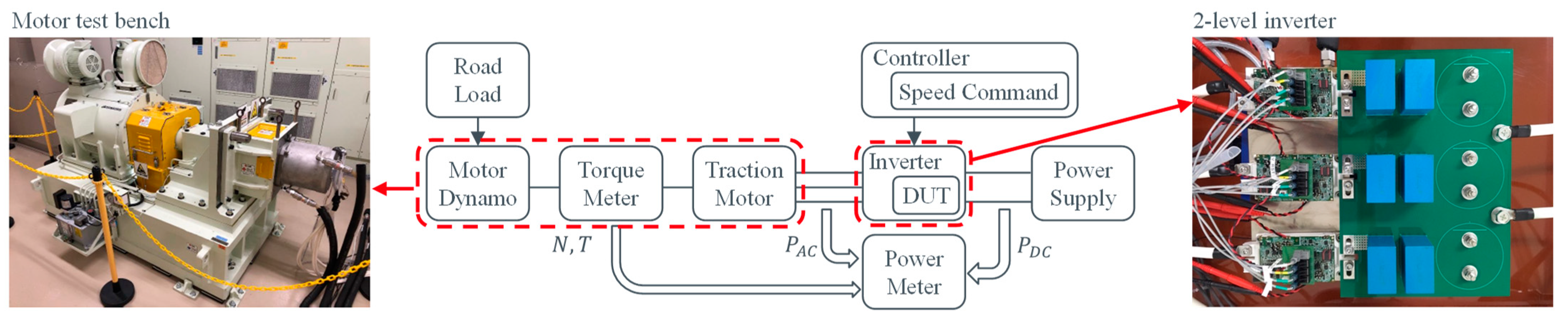
2.1. System Configuration Outline

Figure 1 shows the overall experimental system configuration for evaluating power modules. The device under test (DUT) includes components of a traction inverter and 4 types of power module, namely Infineon Si IGBT (FF450R12ME4), Rohm 2nd generation planar SiC MOSFET (SiC-2G: BSM400D12P2G003), Rohm 3rd generation trench SiC MOSFET (SiC-3G: BSM400D12P2G002), and Rohm 4th generation improved trench SiC MOSFET (SiC-4G: the same module packaging as the others). The power modules are selected under the condition of the same module packaging, voltage rating, and current capacity. The specifications of the traction motors of IPMSM and IM are the same as the dynamometer of the motor test bench: 12,000 rpm/300 Nm/100 kW. The dynamometer imitates the preset road load. The controller (PE-Expert4 of Myway Plus) generates a gate drive signal following the worldwide harmonized light vehicles test cycle (WLTC). There are two-line liquid cooling systems for heat dissipation of the motor and the power modules. The coolant is an ethylene glycol-based water solution.
Input and output electric power of the inverter are measured and integrated by the power meter (PW6001 of Hioki) with the current sensors (CT6876 of Hioki) and motor power is calculated with number of rotations and torque measured by the torque meter (T40B of HBM). Table 1 presents the equipment details.

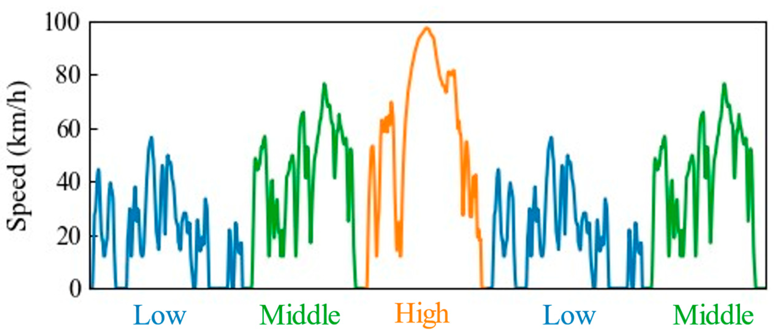
2.2. Experimental Conditions

The evaluation cycle shown in Figure 2 illustrates the pre-set reference vehicle speed to control motor speed by the controller. This is one dynamic segment of the WLTC Class 3b Shortened Type 1 test that excludes the extra high-speed phase in Japan. The original Shortened Type 1 test has two dynamic segments and two continuous speed segments [44]. We did not conduct a reproduction of the battery profile, and battery voltage drop depended on current in this study for simplifying the following analyses.
The motor dynamo determines the road load as follows:
T R / L = J · ω ˙ + 0.5 C d A ρ v 2 + μ m g · r / G
where T R / L is the road load torque; J is the vehicle inertia automatically calculated with set vehicle parameters in the motor dynamo system; ω ˙ is the angular acceleration; C d is the aerodynamic drag coefficient; A is the frontal area; ρ is the air density; v is the vehicle speed; μ is the rolling resistance coefficient; m is the vehicle mass; g is the gravity constant; r is the tire radius; G is the gear ratio.
We choose two vehicles for comparative evaluation. One is the 2017 Nissan Leaf G which is one of the major EVs in Japan. The other is the 2022 BMW i4 eDrive 40 whose required current is the maximum in other vehicles for which we set available parameters. Table 2 presents vehicle parameters for calculating road load [45].
In this paper, we set the inverter input voltage as 800 V for high voltage use evaluation although the battery voltage of the original vehicles is around 400 V. The gate resistance values of each type of power module are decided such that the peak voltage of the switching surge is approximately 1100 V when the test current is approximately 800 A in the double pulse test. The on-/off- gate resistances of Si IGBT, SiC-2G, SiC-3G, and SiC-4G are 0.0/6.8 Ω, 1.2/2.2 Ω, 1.2/2.2 Ω, and 2.7/6.8 Ω. The gate driver circuit (BSMGD2G17D24-EVK001) can output the recommended gate voltage for the inverter use of SiC power modules, while negative voltage for Si IGBT is limited to −4 V. The on-/off- gate voltages of Si IGBT, SiC-2G, SiC-3G, and SiC-4G are 15/−4 V, 18/−4 V, 18/−2 V, and 18/−2 V. The switching frequency and the dead time of the inverter are set 10 kHz and 2 us. The list of parameters is shown in Table 3.

2.3. Evaluation Index

The original energy consumption requires complex calculation procedures [41]. However, in this paper, we employed a simplified calculation as follows:
E C = E C DC / D
where E C is the energy consumption per 100 km; E C D C is the total integrated inverter input energy; D is the total driving distance standardized by 100 km.
E C DC = P DC · τ 1
where P DC is the inverter input power; Δ τ 1 is 50 ms (refresh rate is 20 Hz) and is set by the accumulation function of the power meter, PW6001.
D = 2 π r · N total / 4096 · G
where N total is the total number of the a/b pulses converted from a resolver of the traction motor; G is the gear ratio.
The integrated inverter loss energy E loss _ inv is calculated as follows:
E loss _ inv = P DC P AC · τ 1
where P AC is inverter output power.
The integrated motor loss energy E loss _ mtr is calculated as follows:
E loss _ mtr = P AC · τ 1 E trc
where E trc is the traction energy.
The traction energy E trc is calculated as follows:
E trc = P MC · τ 2
where P MC is the motor output; τ 2 is approximately 200 milliseconds (refresh rate is 5 Hz) and is decided by the data accumulation speed between a PC and other measurement equipment.
The motor output P MC is calculated as follows:
P MC = 2 π · T · N / 60
where T is the torque and N is the number of rotations. Both parameters are measured using the torque meter.

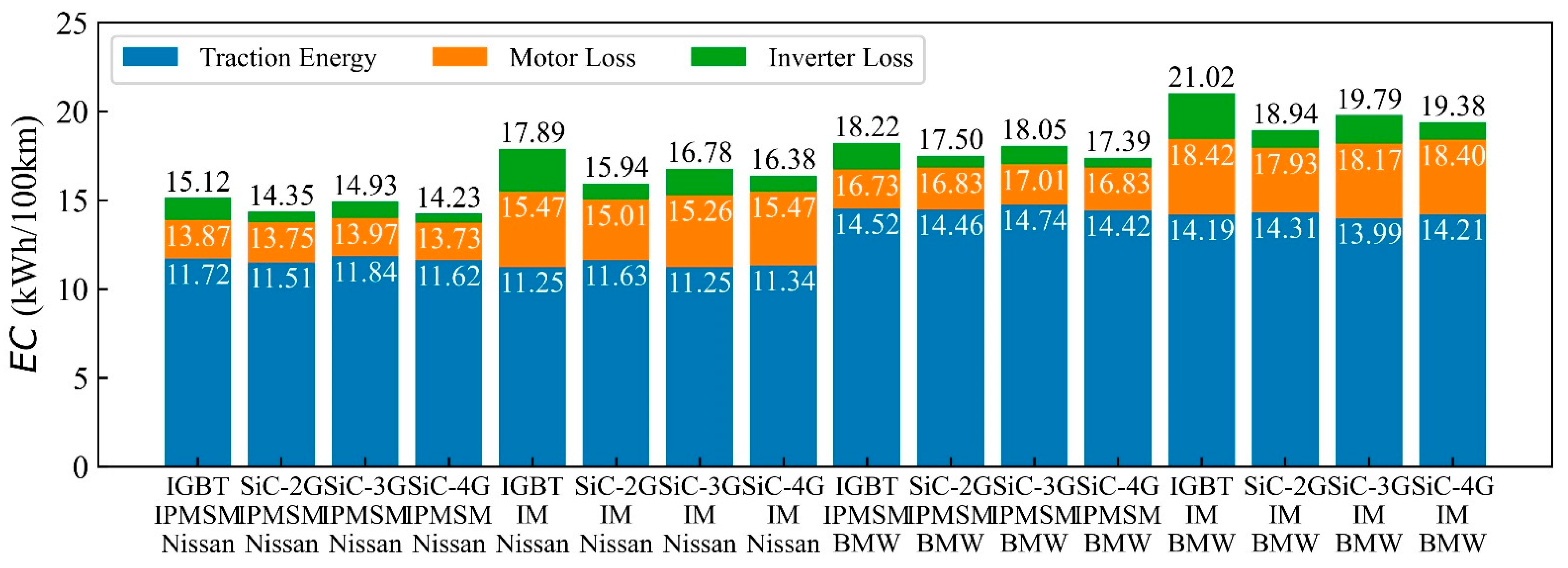
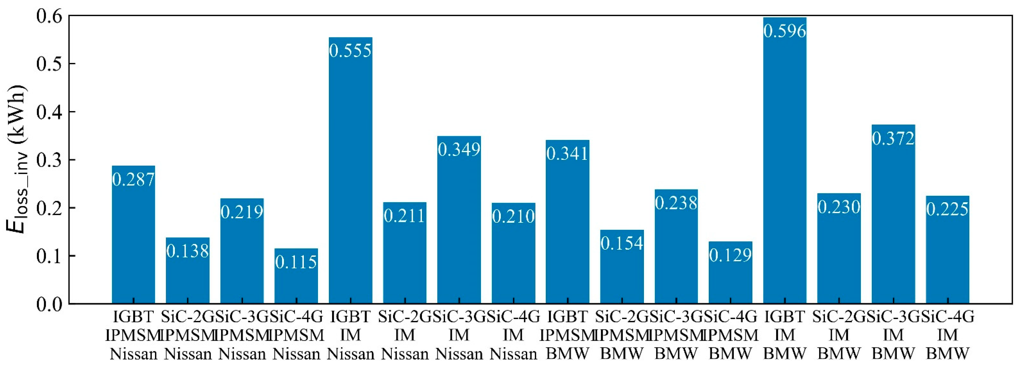
3. Experimental Results and Discussion

In Figure 3, total energy consumption overall the evaluation cycle is compared in a combination of three categories, a type of power modules, traction motors and target vehicles. Each stacked bar of EC is color-coded by three categories, traction energy, motor loss energy, and inverter loss energy. Each data label on the bars means traction energy consumption (ECtrc) calculated with only traction energy, mechanical energy consumption (ECmc) with traction energy and motor loss energy, and total energy consumption (ECttl) with energy of all 3 categories. ECttl and ECmc are important values because the accuracy is guaranteed by the power meter. On the other hand, ECtrc is just a reference value because the torque meter does not guarantee the accuracy of transient response and the refresh rate of communication speed is slow. The ratio of the traction energy and the motor loss energy is not so accurate.
In the case of driving IPMSM, the good order of ECttl in the types of power modules is SiC-4G < SiC-2G < SiC-3G < Si IGBT regardless of the target vehicles. The order of ECmc is SiC-4G ≈ SiC-2G < Si IGBT < SiC-3G in Nissan Leaf G and Si IGBT < SiC-4G ≈ SiC-2G < SiC-3G in BMW i4 eDrive 40. SiC MOSFETs much improve the total energy consumption, whereas motor loss can be increased since the traction energy should be uniquely determined by vehicle parameters.
In the case of driving IM, the order of ECttl is SiC-2G < SiC-4G < SiC-3G < Si IGBT and the order of ECmc is SiC-2G < SiC-3G < SiC-4G ≈ Si IGBT regardless of the vehicles. All SiC MOSFETs demonstrated better performance than Si IGBT. SiC-2G of planar structure realizes the best energy saving although SiC-3G and -4G of the trench have better standalone device characteristics.
Pure inverter losses are shown in Figure 4. The lowest order of the loss is SiC-4G < SiC-2G < SiC-3G < Si IGBT regardless of the motor types and the target vehicles. The difference in material properties is very clear. The remarkable point is that SiC-2G of the planar can keep the loss lower than SiC-3G of the trench in power converter level.
Figure 5 shows the relationship of EC and power train loss of Eloss_mtr and Eloss_inv. The results in Figure 5a are calculated with the data of the overall evaluation cycle of one dynamic segment. Figure 5b–d show the data of the low, middle, and high phases of the cycle. The dashed line shows the Nissan Leaf G and the dot-dashed line the BMW i4 eDrive 40. The two lines are drawn by each simple average of all data. The slop of those lines signifies the impact of the powertrain loss on EC. In the low phase shown in Figure 5b, a short drive distance makes the slope of each line steep, and therefore the loss reduction effect is easily apparent as an improvement in energy consumption. On the other hand, in the high phase shown in Figure 5d, the loss has only a limited effect on energy consumption since the slope of each line is loose. The intercept of each line represents experimentally obtained ideal energy consumption ignoring motor and inverter loss. The intercept is approximately 11.56 kWh/100 km for the Nissan Leaf G, and approximately 14.41 kWh/100 km for the BMW i4 eDrive 40, as shown in Figure 5a. Therefore, the energy increase in traction purely due to the difference between the target vehicles is approximately 25%.
The filled markers in Figure 3 represent motor loss. The motor loss increases in the order of low, middle, and high phase as drive distance increases. The markers are roughly overlapped if grouped by the target vehicles and the motor type except SiC-2G of IM. The open markers mean the total value of motor loss and inverter loss. The distance between the filled and the open marker of the same color and shape shows the amount of inverter loss and the amount of improvable energy consumption. Figure 5 helps to visually understand the ratio and the amount of motor and inverter loss, and the effect of each loss on energy consumption.
Figure 6 shows percentages of traction energy, motor loss energy, and inverter loss energy in each ECttl. The inverter loss ratio of SiC-4G is the lowest regardless of the motor types and the target vehicles.

4. Conclusions

In this paper, we investigated the effects of device materials and structures on the power converter and the EV system by just replacing power modules. Two types of vehicle parameter sets did not influence the trend of results except for increasing the required overall energy for the evaluation cycle of one dynamic segment of the Japanese WLTC. However, types of power modules and motors affected inverter loss and mechanical energy converted to traction. The good order in inverter loss and energy consumption was not equal to the individual performance of evaluated power modules, i.e., in the order of Si IGBT, SiC-2G (planar SiC MOSFET), SiC-3G (trench SiC MOSFET), and SiC-4G (improved trench SiC MOSFET). In addition, the type of power module can influence the motor loss.
SiC-2G demonstrated good balance in terms of inverter loss, motor loss, and energy consumption. SiC-4G had the lowest inverter loss and reduced energy consumption to 3% of the entire energy in the case of driving IPMSM. On the other hand, the mechanical energy of SiC-4G is the same as Si IGBT in the case of driving IM. Our future work aims to find what device parameters influence motor loss, mechanical energy, and energy consumption.

Author Contributions

Conceptualization, H.U. and K.N.; methodology, H.U.; software, H.U.; validation, H.U.; formal analysis, H.U.; investigation, H.U. and T.H.; resources, K.N.; data curation, H.U. and T.H.; writing—original draft, H.U.; visualization, H.U.; supervision, K.N.; project administration, K.N.; funding acquisition, K.N. All authors have read and agreed to the published version of the manuscript.

Funding

This research received no external funding.

Data Availability Statement

Not applicable.

Conflicts of Interest

The authors declare no conflict of interest.

References

  1. Kazemzadeh, E.; Koengkan, M.; Fuinhas, A.J.; Mejdalani, A. Impact of Electrification of Road Transport on Premature Deaths from Outdoor Air Pollution: A Macroeconomic Evidence from 29 European Countries. World Electr. Veh. J. 2022, 13, 155. [Google Scholar] [CrossRef]
  2. Kromer, A.M.; Bandivadekar, A.; Evans, C. Long-term greenhouse gas emission and petroleum reduction goals: Evolutionary pathways for the light-duty vehicle sector. Energy 2010, 35, 387–397. [Google Scholar] [CrossRef]
  3. Hasselwander, S.; Galich, A.; Nieland, S. Impact of Climate Change on the Energy Consumption of Passenger Car Vehicles. World Electr. Veh. J. 2022, 13, 146. [Google Scholar]
  4. Elasser, A.; Chow, P.T. Silicon carbide benefits and advantages for power electronics circuits and systems. Proc. IEEE 2022, 90, 969–986. [Google Scholar] [CrossRef]
  5. Spaziani, L.; Lu, L. Silicon, GaN and SiC: There’s room for all: An application space overview of device considerations. In Proceedings of the 2018 IEEE 30th International Symposium on Power Semiconductor Devices and ICs (ISPSD), Chicago, IL, USA, 13–17 May 2018. [Google Scholar]
  6. Agarwal, K.A. An overview of SiC power devices. In Proceedings of the 2010 International Conference on Power, Control and Embedded Systems, Allahabad, India, 29 November–1 December 2010. [Google Scholar]
  7. Kaminski, N.; Hilt, O. SiC and GaN Devices—Competition or Coexistence? In Proceedings of the 2012 7th International Conference on Integrated Power Electronics Systems (CIPS), Nuremberg, Germany, 6–8 March 2012.
  8. Lee, S.J.; Chun, H.D.; Park, H.J.; Jung, K.Y.; Kang, G.E.; Sung, Y.M. Design of a novel SiC MOSFET structure for EV inverter efficiency improvement. In Proceedings of the 2014 IEEE 26th International Symposium on Power Semiconductor Devices & IC’s (ISPSD), Waikoloa, HI, USA, 15–19 June 2014. [Google Scholar]
  9. Zhang, L.; Dai, T.; Gammon, P.; Shah, V.; Mawby, P.; Antoniou, M. Comparison of a 3.3 kV SiC Hybrid-Channel Trench MOSFET and a Planar MOSFET. In Proceedings of the 2022 IEEE Workshop on Wide Bandgap Power Devices and Applications in Europe (WiPDA Europe), Coventry, UK, 18–20 September 2022. [Google Scholar]
  10. Chaturvedi, M.; Dimitrijev, S.; Haasmann, D.; Moghadam, A.H.; Pande, P.; Jadli, U. Comparison of Commercial Planar and Trench SiC MOSFETs by Electrical Characterization of Performance-Degrading Near-Interface Traps. IEEE Trans. Electron Devices 2022, 69, 6225–6230. [Google Scholar] [CrossRef]
  11. Tian, K.; Hallen, A.; Qi, J.; Nawaz, M.; Ma, S.; Wang, M.; Guo, S.; Elg, K. Comprehensive Characterization of the 4H-SiC Planar and Trench Gate MOSFETs From Cryogenic to High Temperature. IEEE Trans. Electron Devices 2019, 66, 4279–4286. [Google Scholar] [CrossRef]
  12. Fukunaga, S.; Castellazzi, A.; Funaki, T. Development of reliable multi-chip power modules with parallel planar- and trench-gate SiC MOSFETs. In Proceedings of the 2022 IEEE 34th International Symposium on Power Semiconductor Devices and ICs (ISPSD), Vancouver, BC, Canada, 22–25 May 2022. [Google Scholar]
  13. Bashar, E.; Agbo, N.; Wu, R.; Mendy, S.; Jahdi, S.; Jennings, M.; Withey, A.; Evans, S.; Davies, G.; Demitrove, J.; et al. A Review of Short Circuit Performance in 650 V Power Devices: SiC MOSFETs, Silicon Super-junction MOSFETs, SiC Cascode JFETs, Silicon MOSFETs and Silicon IGBTs. In Proceedings of the PCIM Europe 2022; International Exhibition and Conference for Power Electronics, Intelligent Motion, Renewable Energy and Energy Management, Nuremberg, Germany, 10–12 May 2022. [Google Scholar]
  14. Cao, L.; Guo, Q.; Sheng, K. Comparative Evaluation of the Short circuit Capability of SiC Planar and Trench Power MOSFET. In Proceedings of the 2018 IEEE 2nd International Electrical and Energy Conference (CIEEC), Beijing, China, 4–6 November 2018. [Google Scholar]
  15. Huang, W.; Deng, X.; Li, X.; Wen, Y.; Li, X.; Li, Z.; Zhang, B. Investigation of Surge Current Reliability of 1200 V Planar and Trench SiC MOSFET. In Proceedings of the 2020 IEEE 15th International Conference on Solid-State & Integrated Circuit Technology (ICSICT), Kunming, China, 3–6 November 2020. [Google Scholar]
  16. Murakami, Y.; Tajima, Y.; Tanimoto, S. Air-cooled full-SiC high power density inverter unit. In Proceedings of the 2013 World Electric Vehicle Symposium and Exhibition (EVS27), Barcelona, Spain, 17–20 November 2013. [Google Scholar]
  17. Yamaguchi, K. Design and evaluation of SiC-based high power density inverter, 70 kW/liter, 50 kW/kg. In Proceedings of the 2018 IEEE Applied Power Electronics Conference and Exposition (APEC), San Antonio, TX, USA, 4–8 March 2018. [Google Scholar]
  18. Shi YWang, L.; Xie, R.; Li, H. Design and implementation of a 100 kW SiC filter-less PV inverter with 5 kW/kg power density and 99.2% CEC efficiency. In Proceedings of the 2018 IEEE Applied Power Electronics Conference and Exposition (APEC), San Antonio, TX, USA, 4–8 March 2018. [Google Scholar]
  19. Sakasegawa, E.; Chishiki, R.; Sedutsu, R.; Soeda, T.; Haga, H.; Kennel, M.R. Comparison of Interleaved Boost Converter and Two-Phase Boost Converter Characteristics for Three-Level Inverters. World Electr. Veh. J. 2023, 14, 7. [Google Scholar] [CrossRef]
  20. Deng, W.; Zhao, Y.; Wu, J. Energy Efficiency Improvement via Bus Voltage Control of Inverter for Electric Vehicles. IEEE Trans. Veh. Technol. 2017, 66, 1063–1073. [Google Scholar] [CrossRef]
  21. Mazumder, S.K.; Acharya, K.; Jedraszczak, P. High-temperature all-SiC bidirectional DC/DC converter for plug-in-hybrid vehicle (PHEV). In Proceedings of the 2008 34th Annual Conference of IEEE Industrial Electronics, Orlando, FL, USA, 10–13 November 2008. [Google Scholar]
  22. Everts, J.; Das, J.; Keybus DV, J.; Genoe, J.; Germain, M.; Driesen, J. A high-efficiency, high-frequency boost converter using enhancement mode GaN DHFETs on silicon. In Proceedings of the 2010 IEEE Energy Conversion Congress and Exposition, Atlanta, GA, USA, 12–16 September 2010. [Google Scholar]
  23. Shang, F.; Arribas, P.A.; Krishnamurthy, M. A comprehensive evaluation of SiC devices in traction applications. In Proceedings of the 2014 IEEE Transportation Electrification Conference and Expo (ITEC), Dearborn, MI, USA, 15–18 June 2014. [Google Scholar]
  24. Ozdemir, S.; Acar, F.; Selamogullari, S.U. Comparison of silicon carbide MOSFET and IGBT based electric vehicle traction inverters. In Proceedings of the 2015 International Conference on Electrical Engineering and Informatics (ICEEI), Denpasar, Indonesia, 10–11 August 2015. [Google Scholar]
  25. Zhao, T.; Wang, J.; Huang, Q.A.; Agrwal, A. Comparisons of SiC MOSFET and Si IGBT Based Motor Drive Systems. In Proceedings of the 2007 IEEE Industry Applications Annual Meeting, New Orleans, LA, USA, 23–27 September 2007. [Google Scholar]
  26. Wang, G.; Wang, F.; Magai, G.; Lei, Y.; Huang, A.; Das, M. Performance comparison of 1200 V 100A SiC MOSFET and 1200 V 100A silicon IGBT. In Proceedings of the 2013 IEEE Energy Conversion Congress and Exposition, Denver, CO, USA, 15–19 September 2013. [Google Scholar]
  27. Zhang, L.; Yuan, X.; Wu, X.; Shi, C.; Zhang, J.; Zhang, Y. Performance Evaluation of High-Power SiC MOSFET Modules in Comparison to Si IGBT Modules. IEEE Trans. Power Electron. 2019, 34, 1181–1196. [Google Scholar] [CrossRef]
  28. Allca-Pekarovic, A.; Kollmeyer, P.J.; Mahvelatishamsabadi, P.; Mirfakhrai, T.; Naghshtabrizi, P.; Emadi, A. Comparison of IGBT and SiC Inverter Loss for 400 V and 800 V DC Bus Electric Vehicle Drivetrains. In Proceedings of the 2020 IEEE Energy Conversion Congress and Exposition (ECCE), Detroit, MI, USA, 11–15 October 2020. [Google Scholar]
  29. Menon, R.; Azeez, A.N.; Kadam, H.A.; Williamson, S.S. Energy loss analysis of traction inverter drive for different PWM techniques and drive cycles. In Proceedings of the 2018 IEEE International Conference on Industrial Electronics for Sustainable Energy Systems (IESES), Hamilton, New Zealand, 31 January–2 February 2018. [Google Scholar]
  30. Amirpour, S.; Thiringer, T.; Hagstedt, D. Mission-Profile-Based Lifetime Study for SiC/IGBT Modules in a Propulsion Inverter. In Proceedings of the 2021 IEEE 19th International Power Electronics and Motion Control Conference (PEMC), Gliwice, Poland, 25–29 April 2021. [Google Scholar]
  31. Nisch, A.; Heller, M.; Wondrak, W.; Bucher, A.; Hasenohr, C.; Kefer, K.; Lunz, B.; Pawellek, A.; Smit, A.; Gartner, M.; et al. Simulation and Measurement-Based Analysis of Efficiency Improvement of SiC MOSFETs in a Series-Production Ready 300 kW/400 V Automotive Traction Inverter. In Proceedings of the 2020 22nd European Conference on Power Electronics and Applications (EPE’20 ECCE Europe), Lyon, France, 7–11 September 2020. [Google Scholar]
  32. Milligan, R.; Muneer, T.; Smith, I. A comparative range approach using the Real World Drive Cycles and the Battery Electric Vehicle. In Proceedings of the 2015 IEEE International Transportation Electrification Conference (ITEC), Chennai, India, 27–29 August 2015. [Google Scholar]
  33. Charadsuksawat, A.; Laoonual, Y.; Chollacoop, N. Comparative Study of Hybrid Electric Vehicle and Conventional Vehicle Under New European Driving Cycle and Bangkok Driving Cycle. In Proceedings of the 2018 IEEE Transportation Electrification Conference and Expo, Asia-Pacific (ITEC Asia-Pacific), Bangkok, Thailand, 6–9 June 2018. [Google Scholar]
  34. Chen, L.; Wang, J.; Lazari, P.; Chen, X. Optimizations of a permanent magnet machine targeting different driving cycles for electric vehicles. In Proceedings of the 2013 International Electric Machines & Drives Conference, Chicago, IL, USA, 12–15 May 2013. [Google Scholar]
  35. Gunther, S.; Ulbrich, S.; Hofmann, W. Driving cycle-based design optimization of interior permanent magnet synchronous motor drives for electric vehicle application. In Proceedings of the 2014 International Symposium on Power Electronics, Electrical Drives, Automation and Motion, Ischia, Italy, 18–20 June 2014. [Google Scholar]
  36. Patzak, A.; Bachheibl, F.; Baumgardt, A.; Dajaku, G.; Moros, O.; Gerling, D. Driving range evaluation of a multi-phase drive for low voltage high power electric vehicles. In Proceedings of the 2015 International Conference on Sustainable Mobility Applications, Renewables and Technology (SMART), Kuwait, Kuwait, 23–25 November 2015. [Google Scholar]
  37. Trench-Structure SiC-MOSFET and Actual Products. Available online: https://techweb.rohm.com/product/power-device/sic/sic-basic/6574/ (accessed on 1 February 2023).
  38. New Products Under Development 3rd Gen, SCI. MOSFET. Available online: https://www.rohm.com/documents/11303/2871848/3rd-gen-MOSFETs.pdf (accessed on 1 February 2023).
  39. New 4th Generation SiC MOSFETs Featuring the Industry’s Lowest on Resistance. Available online: https://www.rohm.com/news-detail?news-title=new-4th-gen-sic-mosfets&defaultGroupId=false (accessed on 1 February 2023).
  40. Disruptive Technology: ROHM Generation 4, SIC MOSFET. Available online: https://www.techinsights.com/blog/disruptive-technology-rohm-generation-4-sic-mosfet (accessed on 1 February 2023).
  41. Infineon IGBT Module FF450R12ME4. Available online: https://www.infineon.com/dgdl/Infineon-FF450R12ME4-DS-v03_01-EN.pdf?fileId=db3a30431a5c32f2011a769c4a506c4b (accessed on 1 February 2023).
  42. Rohm Full-SiC Power Module BSM400D12P2G003. Available online: https://fscdn.rohm.com/en/products/databook/datasheet/discrete/sic/power_module/bsm400d12p2g003-e.pdf (accessed on 1 February 2023).
  43. Rohm Full-SiC Power Module BSM400D12P3G002. Available online: https://fscdn.rohm.com/en/products/databook/datasheet/discrete/sic/power_module/bsm400d12p3g002-e.pdf (accessed on 1 February 2023).
  44. United Nations Global Technical Regulation on Worldwide Harmonized Light Vehicles Test Procedures (ECE/TRANS/180/Add.15/Amend.6). Available online: https://unece.org/sites/default/files/2021-01/ECE-TRANS-180a15am6e.pdf (accessed on 1 February 2023).
  45. EVSpecifications Specifications, News and Comparisons. Available online: https://www.evspecifications.com/ (accessed on 1 February 2023).
Figure 1. System configuration diagram.
Wevj 14 00112 g001
Figure 2. Evaluation cycle of one dynamic segment in WLTC Class 3b in Japan.
Wevj 14 00112 g002
Figure 3. Energy consumption of each experimental case.
Wevj 14 00112 g003
Figure 4. Inverter loss comparison between experimental cases.
Wevj 14 00112 g004
Figure 5. Energy consumption vs. powertrain loss of each phase.
Wevj 14 00112 g005
Figure 6. Energy consumption ratio of each experimental case.
Wevj 14 00112 g006
Table 1. Equipment detail.
MakerModelSpecifications
Power SupplySINFONIA TECHNOLOGY-850 V/500 A/100 kW
DUTINFINEONSi IGBT FF450R12ME4 [41]1200 V/450 A
ROHMSiC-2G BSM400D12P2G [42]1200 V/400 A
SiC-3G BSM400D12P3G [43]
SiC-4G prototype
Torque MeterHBMT40B20,000 rpm/500 Nm
Traction MotorMOTION SYSTEM TECHIPMSM850 V/500 A/100kW
12,000 rpm/300 Nm/100 kW
IM
DynamometerSINFONIA TECHNOLOGY-12,000 rpm/300 Nm/100 kW
ControllerMYWAY PLUSPE-EXPERT4-
Power MeterHIOKIPW6001w/CT6876
Table 2. Parameters of test vehicles.
ParameterSymbolUnit2017 Nissan Leaf G2022 BMW i4 eDrive 40
Tire Radiusrm0.3230.356
Gear RatioG-8.1938.774
Aerodynamic Drag CoefficientCd-0.280.24
Frontal AreaAm22.482.41
Vehicle Massmkg16462251
Air Densityρkg/m31.189
Rolling Resistance Coefficientμ-0.011
Gravity Constantgm/s29.8
Table 3. Parameters of driven DUT.
ParameterUnitIGBTSiC-2GSiC-3GSiC-4G
Inverter Input VoltageV800
Inverter Input CapacitorμF960 (320 μF × 3: 947C321K122CDMS)
150 (25 μF × 6: B32778G1256K000)
Snubber CapacitornF4050 (1350 nF × 3: EVSM1D72J2-142H16)
Discharge Resistance0.73 (2.2 MΩ × 3-parallel )
Gate Resistance (ON/OFF)Ω0.0/6.81.2/2.21.2/2.22.7/6.8
Gate Voltage (ON/OFF)V15/–418/–418/–218/–2
Switching FrequencykHz10
Dead Timeus2
Disclaimer/Publisher’s Note: The statements, opinions and data contained in all publications are solely those of the individual author(s) and contributor(s) and not of MDPI and/or the editor(s). MDPI and/or the editor(s) disclaim responsibility for any injury to people or property resulting from any ideas, methods, instructions or products referred to in the content.

