Article

Investigation and Development of Textile Lightweight Bodies for Urban Logistic Vehicles

1
Fraunhofer-Institute for Industrial Engineering IAO, 70569 Stuttgart, Germany
2
German Institutes of Textile and Fiber Research Denkendorf (DITF), 73770 Denkendorf, Germany
3
Erhardt GmbH, 70499 Stuttgart, Germany
*
Author to whom correspondence should be addressed.
World Electr. Veh. J. 2023, 14(5), 121; https://doi.org/10.3390/wevj14050121
Submission received: 13 March 2023 / Revised: 4 April 2023 / Accepted: 27 April 2023 / Published: 4 May 2023

Abstract

:
The urban logistic sector is struggling with the following two problems: a particularly high level of traffic and air pollution. For those reasons, small electric vehicles are the perfect technical solution to cope sustainably with the increasing parcel volume in urban areas. To compensate the weight disadvantage of electric drive, a textile lightweight solution for the body of logistics vehicles is examined in this study. Therefore, various textiles and mounting solutions are examined and developed, as well as tested by multiple testing procedures. The result of this work is an ideal combination of a textile and suitable mounting method for a textile lightweight body for last—mile logistic vehicles.

1. Introduction

Nowadays, inner—city logistics is struggling with two significant problems: first, an increasing volume of parcels has been recorded for the last few years. Second, urban areas are facing air pollution due to the constant increase in traffic [1,2,3,4]. The transportation sector is responsible for the emissions of greenhouse gases and air pollution such as carbon monoxide, unburned hydrocarbons and particulate matter [5]. One effective solution to solve these problems is the use of small electric—driven logistic vehicles for the last—mile in urban areas. Electric driven vehicles are one of the most promising technical solutions because they do not produce local emissions and, depending on the way the electricity is generated, have a huge potential to reduce emissions [6]. From a technical point of view these vehicles represent an ideal application field as they have plannable routes and pre—defined depots [7]. Additionally, electric—driven logistic vehicles are smaller and lighter compared to conventional logistic vehicles. Additionally, the combination of EVs and a lightweight design can reduce environmental impacts [8]. However, the electrification and reduction of the logistic vehicle size as well as the high weight of the battery lead to a reduction in payload which is already smaller for small logistic vehicles. However, the payload is the most important variable in the logistic business.
The main target of this work is to replace conventional parts of small electric logistic vehicles by lightweight components, to compensate the losses. In general, the mass of electric vehicles (EV) is not a new problem. Years ago, EVs were based on conventional vehicle structures, except for the EV components, which led to a high vehicle mass. For example, the BMW i3 was not based on a conventional structure; it had a new lightweight design for electric vehicles [9]. A number of lightweight materials such as aluminium alloys, high strength steel, plastics and composites are integrated in the design of EVs [10].
In terms of the components, it is to improve the weight and additionally to optimize them with technologies from other industries. The cross—industry innovation approach is a methodical approach that explores information across industries. The transfer of knowledge, technologies and know—how from outside the sector is the base of the cross—industry innovation [11]. For this work, the principle of the cross —industry innovation method was used to identify usable technologies, especially textiles and mounting systems. This work specifically focuses on the use of technical textiles in vehicle exteriors, which are investigated. Previous studies have already presented the general feasibility of textiles in the exterior of the vehicles (passenger vehicles). Within this work, textiles for exteriors are transferred into the logistics area [12]. In the case of logistic vehicles, the vehicle body of the cargo space offers a great potential to reduce the weight.

2. State of the Art in Science and Technology

Textiles are already being used in the exterior of logistic vehicles in the form of truck tarpaulins. Truck tarpaulins, which are polyester carrier fabrics with a PVC (polyvinyl chloride) coating on both sides are commercially available in weights of 670 to 900 g/m2 [13,14,15]. They are considered to be highly tear—resistant and serve as a mobile advertising space. In the roof area, translucent PVC tarpaulins are preferred. Horizontal surfaces often suffer, in addition to their own weight, from the weight of snow mass, which can lead to damage. Tarpaulins are attached to the frame of truck bodies using piping, straps, eyelets or similar. However, additional fastenings lead to additional weight. For logistic vehicles with a body made of truck tarpaulins, there is a risk of theft due to cutting into the tarpaulin. Currently, segments made of PVC with attached wires that trigger an alarm when cut represent the solution to this problem [16]. This can also be used to upgrade existing tarpaulins. In the calculation of the permitted total mass of a truck and smaller sized logistic vehicles, saved weight means lower energy consumption and thus the possibility of a higher payload.
Sandwich structures are mainly used for logistic vehicle bodies. Sandwich structures are made up of two face layers and a core material. The core materials usually consist of lightweight foam, or a honeycomb structure enclosed by two solid, force—absorbing surfaces. While the top surface absorbs compressive stress, the core provides cohesion and dissipates shear forces. Often, further layers for heat—insulating or sound—insulating effects are added. The lightweight construction of sandwich structures combines high stiffness and compressive strength at low weight.
The materials used are subject to constant change, driven by increasing requirements in terms of lightweight design, safety, rigidity, reliability, environmental compatibility and economy. The general target from the point of view of lightweight construction is to meet all the requirements of a vehicle components with minimum mass demand. Automotive developers are already presenting approaches in lightweight concept vehicles in which the vehicle exterior is completely covered with a textile. At the beginning of 2019, the simulation of the “Futurelight Camper”, a trailer with a frame made of carbon fibre, was presented by the outdoor company The North Face in collaboration with the BMW Group subsidiary [17]. A waterproof and breathable membrane made of a nanofiber structure covers the frame. It is possible to adjust weight, stretchability, air permeability and robustness in the existing “Futurelight” textile during manufacturing [18]. Details on the realization have not been provided yet.
A very light variant of a sandwich panel structure can be made of polyester resin panels with a glass fibre reinforcement and a PET foam core. With a thickness of about 14 mm, such a panel has a price of about 45 €/m2 and weighs 4.35 kg/m2 [19]. The weight of a commercial truck tarpaulin without a frame starts at about 670 g/m2.
The potential of outdoor textiles to resist UV radiation and intense climatic fluctuations has been proven for quite some time in many fields. They are used in the field of architectural textiles, boat construction, air sports, clothing, tents, garden furniture and sunshades.

3. Methodical Approach

To investigate the usage of textile in urban logistic vehicles, a methodological approach has been developed consisting of four individual steps. This approach was developed independent of materials or technologies. This offers the opportunity to transfer the method to other materials or mounting systems and supports the development of further exterior components for light electric last mile delivery vehicles through a methodical sequence of steps to be carried out. The first step is the identification of basic requirements. Based on the defined requirements, textiles are researched that are already used in various areas and industries in the exterior, followed by the selection of the most prospective ones. Basic tests of the textiles help to verify the compliance with the requirements. Mounting possibilities for textiles at the construction of the vehicle body have also been researched, selected and tested. The results were merged and transferred into early prototypes. Using these early prototypes, further tests such as weathering, air flow (wind tunnel) as well as cargo securing, and the load resistance of the lateral surface were executed. After all tests were completed, one textile and one mounting mechanism were assembled in a prototype. Figure 1 shows the approach.
Basic Requirements: The identification of the basic requirements consists of the definition of the application area, the components, and legal requirements. The first step is the definition of the application area, in this case the vehicle category such as passenger transportation, logistic transportation, etc. If the application area is defined, the components, which should be replaced by textiles, have to be defined. If the components are defined, research about the valid legal requirements is necessary to obtain information about the legal framework and vehicle registration. To obtain the information, research of literature and laws was necessary. The research project was located in Germany; therefore, the German laws were focused on for the research of laws. In addition, further technical, emotional, and aesthetic requirements are included which is important for the product development later.
Textiles: To find suitable textiles for the use case, eligible materials are researched for the application, based on a material and availability research. This involves searching the use case industries but also in external industries. Based on the technical specification, researched textiles are shortlisted. These textiles are subject to comprehensive laboratory testing such as artificial weathering, soiling and cleaning behaviour, the determination of water and oil mark or burst properties. The three most convincing textiles, which meet the requirements for use in logistic bodies are selected to execute further tests [20].
Mounting: Mounting techniques must be researched and reviewed to find the most suitable joining technique for the special use case. Afterwards, they are systematically evaluated whether they can be transferred to the application. The individual mounting techniques must be tested under laboratory conditions.
Tests: Once the textiles and mounting mechanism are selected and tested under laboratory conditions, pre—prototypes of the construction are created and tested as a system. In this use case, three different tests with a prototype are performed:
Wind tunnel test: In a wind tunnel test, the effect of the flow around the pre—prototype is tested. With the airflow, the tensile and compressive force on the textile and the deformation of the textiles (fluttering) measured.
Load test: A drop test is conducted to check the mechanical resilience of the lateral surface (textile) and mountings. The test simulates an impact of the package on the lateral surface of the body when driving along curves by “falling” onto the textile surface with the same force. Accordingly, a calculation of the impact force is performed to generate consistent values of a curve run.
Weathering test: The textile is tested in an endurance test by being exposed to all climatic conditions for 12 months. This shall examine the weather compatibility of the textiles and mounting systems.
Figure 2 shows the several principles of testing.
Prototype: After implementing and evaluating the tests, a prototype of the logistics body has been built. The prototype contains both the most appropriate textile as well as the most appropriate mounting mechanism, selected by taking the basic requirements into account.
This methodical approach was applied in this work to generate knowledge about the usage of textiles for vehicle bodies for urban logistic vehicles.

4. Results

According to the methodical approach developed in this project, the research work was conducted, and the results presented in this chapter were obtained.

4.1. Basic Requirements

The application areas in this project were predefined through the project partner. The usage of textiles in the vehicle exterior should be analysed in logistic transportation and in passenger transportation. This paper shows only the results of logistic transportation; the methodical approach is the same for both application areas. The results of passenger transportation may follow in another scientific paperwork. For the logistic transportation, the focus was set on an urban logistic vehicle (<3.5 t).
To define the component which should be replaced by textiles, a workshop with relevant project partners was conducted. In this meeting a lot of “textile” ideas came up. At urban logistic vehicles, the most prospective assembly group for a “textilization” was the vehicle body. The experts in the project have seen the highest potential to reduce weight in that assembly group. The whole sides of the body can be designed by textiles. Additionally, mechanical elements such as roller blinds and sliding doors should be analysed in that work. For a higher resistance of the textiles, the inside of the textiles should be protected by a textile net. This could be necessary if the textiles get impacted by moving packages inside of the cargo hold. Summarised, the following components should be implemented:
  • Vehicle body with textile sides
  • Inner textile net for a higher resistance
  • Roller blinds and sliding doors.
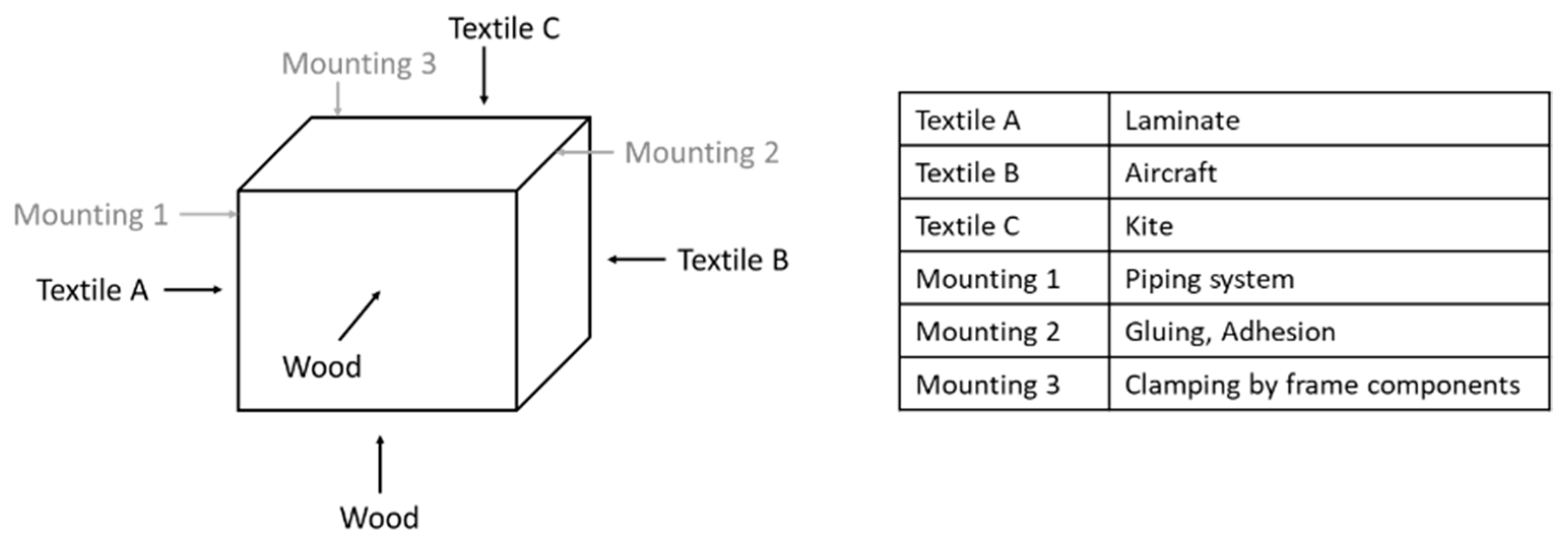
After defining the components, the legal requirements for the construction of urban logistic vehicle bodies must be researched. Before this step, the daily use—case of an urban logistic vehicle was elaborated for a same understanding of the research object. There exist a few legal (technical) requirements (for the defined user region Germany) for the construction of a logistic vehicle body. The most relevant for this project were:
  • no sharp, pointed or protruding edges [21]
  • closable, also while driving [22]
  • width of 2.55 m and height of 4 m must not be exceeded [23]
  • lashing possibilities must be installed [24].
In addition to the legal technical requirements, further technical, emotional, and aesthetical requirements also were considered (Table 1).
A catalogue of requirements for further research and development of the textiles and mounting techniques was drawn up based on the basic requirements identified.

4.2. Textiles

Based on the basic requirements identified in chapter 4.1, specific technical requirements for the textile were derived and defined. These technical requirements include, for example, a water tightness of a 1500 mm water column, an air impermeability of >5 L/m2/s, an UV resistance of 5 years, climate resistance at temperatures from −10 °C to +70 °C, no wetting of oil and water, dirt repellence and a weight that is well below 520 g/m2, (equivalent to the weight of conventional PVC truck tarpaulin) [13,14,15]. In a first step, textiles already available on the market from various outdoor sectors such as construction textiles, tents, boat building, air sports, sun protection and outdoor clothing with potential suitability for this project were researched and compared with the defined technical requirements.
In addition, suitable test methods were identified to model the behaviour of the textiles in an actual application, so that an assessment could be made for their suitability for the usage of textile in the vehicle exterior. These are water and oil repellence—the determination of oil and water marks, scratch resistance—the determination of the tendency for thread pulling and snagging, colour fastness—the determination of colour fastness after artificial weathering with UV irradiation, bursting properties before and after artificial weathering with UV irradiation and soiling and cleaning behaviours. Figure 3 shows an overview of the test methods.
Water repellency and oil repellency: For use in vehicle exteriors, cleaning is considered a necessity. The repellence of oil— and water—containing liquids should therefore not lose its effect. The determination of the oil repellence (DIN EN ISO 14419) and water repellence (“3M—Water repellency”) were tested on the textiles before and after three cleanings with a cleaning agent typical for the automotive sector (car shampoo concentrate R527 from Förch) and a commercially available all—purpose cleaner (neutral cleaner from Frosch). In addition, the “colour stain test”, a test developed at the DITF, was performed, in which the wetting behaviour is evaluated with a dye solution. For the application in automotive exteriors, the test is intended to reveal no wetting of the textile.
Scratch resistance: The Orbitor Pilling and Snagging Tester 516 was selected for testing the pilling tendency and snagging. The corresponding standard is BS 8479. This test was selected to produce results similar to the striping or snagging of a bush with thorns and spines when the vehicle is parked. The determination of the thread pulling tendency and the snagging proved the robustness of the textile under the influence of sharp objects, which can cause damage to the surface of coatings, holes or thread pullers. As a comparison and confirmation, a test was performed with branches with spines of a rose plant, which were pulled over the textiles.
Artificial irradiation and weathering: Artificial irradiation and weathering was selected to mimic time—accelerated aging. The influence of weather and solar radiation varies greatly depending on the climatic zone. Artificial aging was performed according to the climatic zone “Central Europe” with treatment cycles set up at the DITF. The test includes temperature changes from −10 to +70 °C, humidity changes and irradiation with global radiation. For the artificial irradiation and weathering with UV fluorescent lamps, a UV—global tester “Weiss UV200” was used. The procedure was carried out in accordance with the standard DIN EN ISO 4892-3. Artificial weathering can deviate from the behaviour under practical conditions during long—term outdoor weathering. The effect of photodegradation was then determined with colour fastness and the determination of the bursting strength.
Colour Fastness: The effect of weathering on the colour can cause the complete loss of it. The loss of the colour means at the same time the loss of the aesthetics expected by the customer. The colour before and after weathering and irradiation was measured on the spectrophotometer “X—rite colour i7” according to the CIELab system under daylight. The corresponding standard is DIN EN 20105—A02.
Bursting properties: The determination of bursting strength was chosen to gain an insight into the possible change in strength in combination with the artificial weathering and irradiation, as well as to gain knowledge of the deformation and recovery of the textiles as a basis for further tests in a wind tunnel. Due to the driving wind, outward pressure on the textiles is expected. The determination of the bursting properties is carried out according to DIN EN 13938-2 with the TruBurst Model 140 using a pneumatic method before and after artificial irradiation and weathering.
Soiling and cleaning behaviour: The aim was to replicate soiling in road traffic. Since the soil composition and the soil application of existing standards and test methods do not correspond to the actual application, an own soil was compiled, consisting of 9.59 g “Leverkusen Standard Soil 40” and 1.71 g brake dust dissolved in 4 L of water. The outside of textiles was brought into direct contact with the soil solution and the water was evaporated completely, depositing the soil on the textile. The textiles were visually assessed.
Subsequent cleaning was carried out with the same cleaning agent used for the oil and water mark. The cleaning tests examine whether the textiles can be cleaned without leaving residues. Figure 4 shows some impressions of the laboratory tests.
Textile A (Laminate) is a three—layer laminate consisting of a polyamide fabric on the outside, a polyurethane membrane in the middle layer and an inner layer of a knitted polyester and elastane fabric. The textile is impregnated oil and water repellent with a fluorocarbon finish. Applications of this textile are motorcycle clothing or backpacks [25].
Textile B (Aircraft) is a woven polyester fabric used as an aircraft covering. The fabric, with a weight of 90 to 210 g/m2, is applied and tensioned by gluing and shrinking by means of heat. The warp and weft density are identical; therefore, the woven textile has no preferred direction. The textile is non—combustible (DIN EN ISO 6941), UV—resistant and air—impermeable. Furthermore, the textile is re—shrinkable. A loss of tension caused by snow or rain load can thus be easily retightened with hot air. The woven textile which is produced in Germany is available in different translucencies. For the roof, a translucent material is preferred to increase the brightness inside the vehicles body [26].
Textile C (Kite) is very light with only 53 g/m2 and is used for kites. It is a double ripstop polyester woven fabric with very low stretch. Furthermore, the fabric is air—impermeable and water repellent [27].
The three textiles were implemented in a pre—prototype with different textiles on each side of the body in order to be able to carry out further tests (see Section 4.4). Figure 5 shows an overview of the test—results of the selected textiles.

4.3. Mounting

A conventional vehicle body consists of sandwich panels with aluminium profiling. Unlike textiles, the sandwich panels have a load—bearing and stabilizing function. Thus, the frame construction for a textile covering must be built differently. Several frame constructions were manufactured and tested for the project as individual elements from commercially available vehicle construction extruded profiles.
To find out whether it is possible to cover the large surfaces of the box structure or whether additional struts are required in the structure, test frames were manufactured, covered, and then tested in a load test (see Section 4.4.3). In addition, various joining techniques such as sewing, gluing, and riveting were examined.
It has been shown that a two—layer structure with an additional inner fabric net for load securing and the protection of the outer textiles is most suitable. For the inner textile, a polyester net fabric coated with PVC with very high tear resistance was chosen. The fabric can be processed both by welding and sewing. Due to its very low price (about 3 €/m2 [28]), it is economically justifiable to replace it in case of damage. For long durability, reinforcements have been sewn on the locations that are prone to a lot of stress due to friction. In addition, piping was applied to distribute forces over the entire surface in the event of an impact. The piping rails were attached to the frame interior with blind rivets, thus pulling in the textile and bringing it to tension.
As a result of the tests, the techniques selected as most appropriate were clamping by frame components, a solution of a piping system and gluing the textile onto the frame. Furthermore, textile B was selected as the outer skin with which good tension can be achieved due to its shrinkage behaviour of 15%. First, the textile was made up to the required size and then the PVC piping was glued on using a dispersion hotmelt adhesive and a hot air blower. Since textiles might lose tension over time due to weathering, it is essential to be able to tension them again. The rail system used has several tensioning grooves to achieve this. The textile is pre—tensioned by means of the piping rails and then finally tensioned with a hot air dryer at a maximum of 180 °C. The textile is then re—tensioned. To further improve the durability and stability of the frames and textiles, additional struts were built in. To keep the weight as low as possible, flexible PVC square profiles were installed, which are both light and stable. The mounting was carried out with blind rivets. Figure 6 shows the results of the mounting research.

4.4. Tests

After the research, selection and testing of promising textiles and mounting techniques, several early prototypes were built to test the whole system with the assembled components. An early prototype is defined as an easy— and fast—to—build but incomplete type of a prototype, as it focusses on those aspects that are necessary for a defined test. Unlike a commonly known prototype, an early prototype only includes properties which are necessary to realize a prototype at an explicit moment for the development of new technologies and to reach the defined testing goals [29].

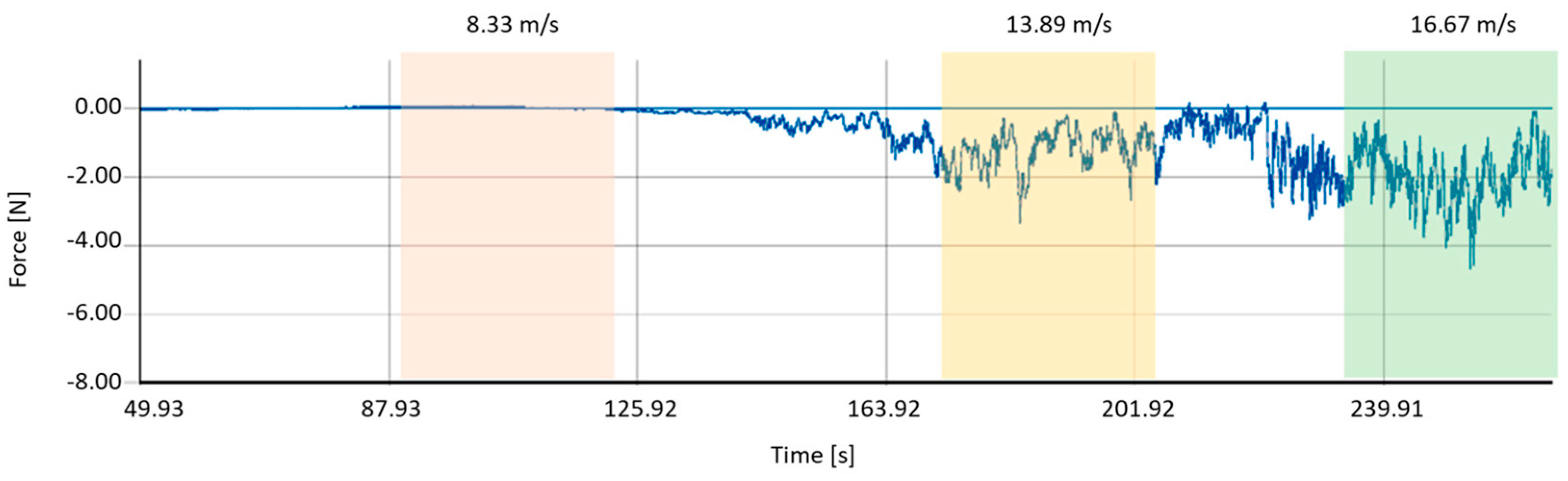
4.4.1. Wind Tunnel Test

For the wind tunnel and weathering test, an early prototype named “the cube”, was built. All sides of the cube have the maximum frame size that a final vehicle body would have (1500 mm). The cube was equipped with the three identified textiles (Section 4.2) and three different mounting techniques (Section 4.3). The front and the bottom side are made of wood. The rear side is made of ordinary textile with two zippers for the entry of the inside of the cube. Figure 7 shows the textile and mounting distribution at the cube.
At the wind tunnel test, the effect of the flow around the cube was tested. For a simulated and continuous air flow, a gust wind tunnel was used. By means of the air flow, the tensile and compressive force on the textile and the deformation of the textiles (fluttering) was measured. The tensile and compressive force is measured by a force gauge, the deformation of the textile by a camera with a slow—motion function. Seven different test runs have been completed to obtain all data for each textile in two flow—around positions of the cube. In position A, the cube was flown around to simulate straight ahead driving (wood/textiles = 90° to the flow). In position B the cube was flown around to simulate cornering (wood/textiles = 45° to the flow). Figure 8 shows the different positions.
The measuring went from 0 m/s to 16.67 m/s. At the wind speed of 8.33 m/s (30 km/h), 13.89 m/s (50 km/h) and 16.67 m/s (60 km/h), the flow was constant for 30 s to obtain consistent conditions for predefined wind speeds.
The results of the wind tunnel test show that textile B (Aircraft) has the best overall values. The fluttering (deformation) and the tensile force show the smallest amplitudes. The laminate (textile A), which has an elastic portion, already showed the first signs of material fatigue after stringing. It performed worst in the wind tunnel test due to strong fluttering, high tensile force and high noise development. Figure 9 shows an example of the measured data at the wind tunnel test (Textile B, aircraft).

4.4.2. Weathering Test

For the weathering test the cube was exposed for an endurance test to the weather. The test period went on for 12 months in all climatic conditions of central Europe, i.e., sun, wind/storm, rain and snow (48.74047623855775, 9.096374837039678). This examined the weather compatibility of the textiles and mounting systems.
The following findings were made after 12 months:
  • Textile C/kite does not resist the weather. Cracks appeared. It became porous.
  • Textile A/3—layer—laminate lost some tension.
  • The adhesive bonding of Textile B/aircraft came off.
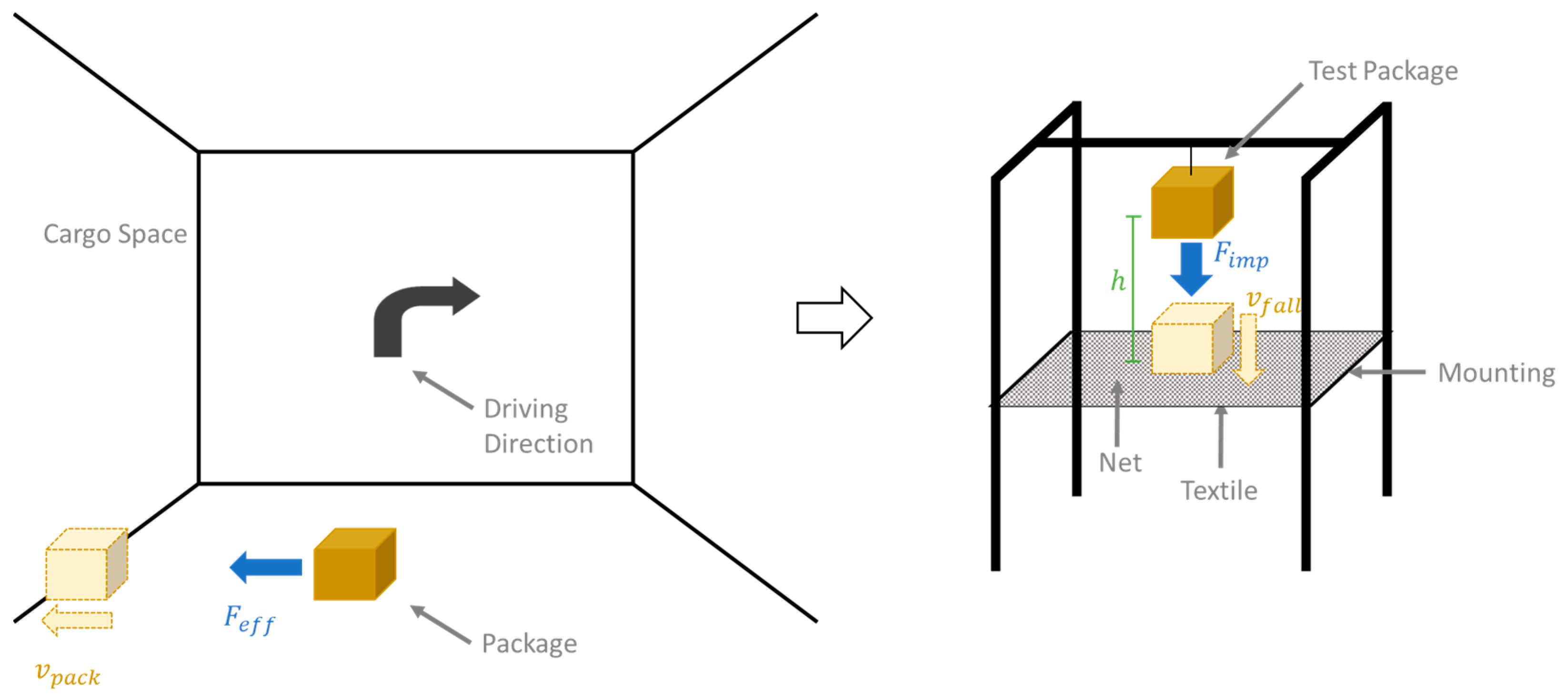
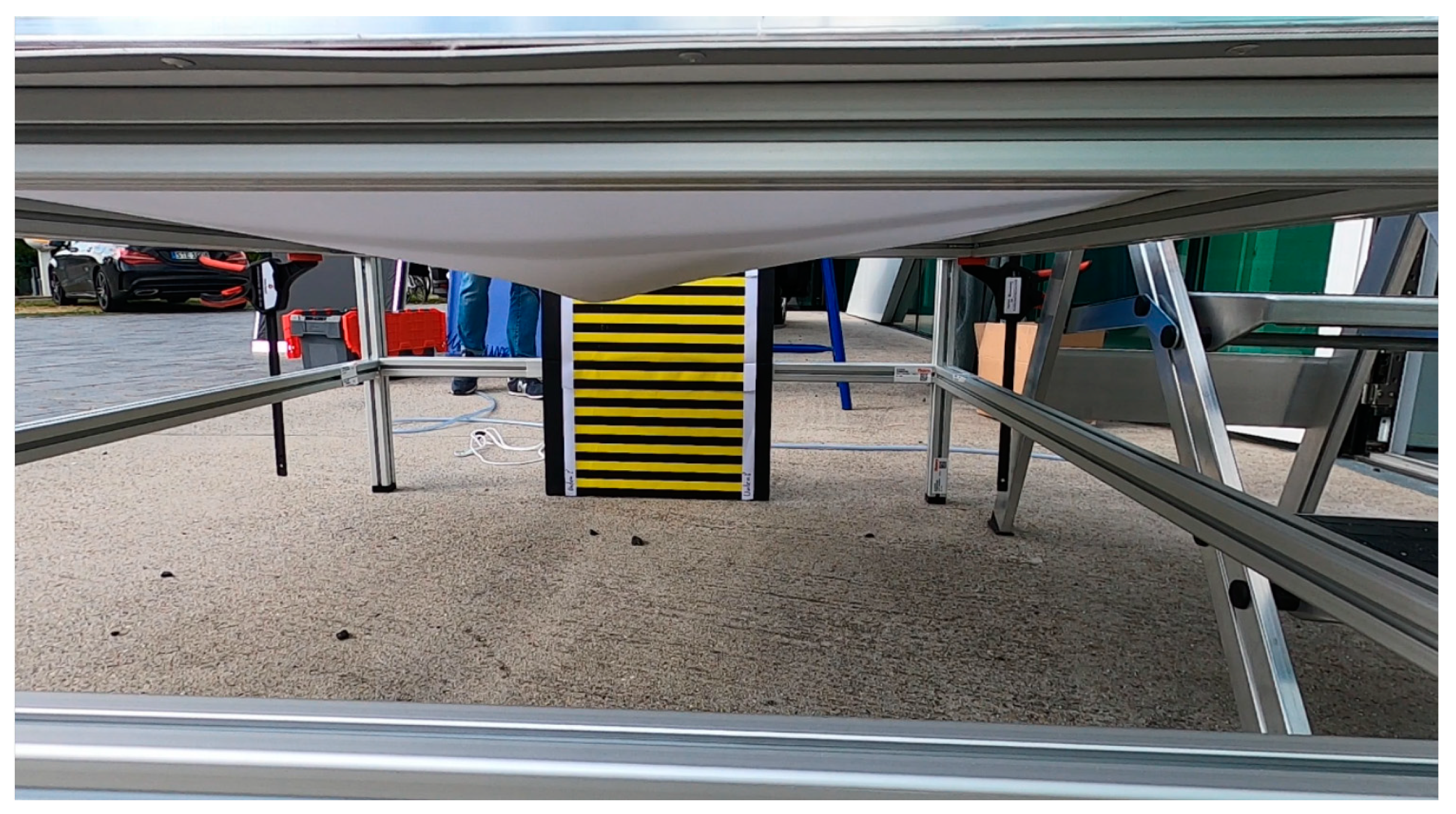
The results after 12 months showed that the textile B/aircraft and the piping system had the best withering properties for the use case as a vehicle body.

4.4.3. Load Test

For the load test, an early prototype was built to check the mechanical resilience of the textile and net at the lateral surface and the mountings. The test simulates an impact of the package on the lateral surface of the vehicle body when driving along curves. Testing this scenario with a vehicle while driving along a curve was too opulent, so a falling test was constructed to simulate a package bumping into the lateral surface from a defined height h , which consists of a net and a textile. Figure 10 shows the technical concept of the load test.
To reach the same force acting in the lateral surface at the falling test ( F e f f = F i m p ), the effective force and the impact force were calculated. The aim of the calculation is to find out the height h ; the package has to fall down to reach the same velocity ( v p a c k = v F a l l ) as a package can have during a bump into the side wall inside the vehicle body.
First, the effective force F e f f had to be calculated, which is determined from the difference between the centripetal force F a   [ N ] during cornering and the frictional force F f r i c :
F e f f = F a F f r i c
The centripetal force F a is the product of the mass of the package m p   [ kg ] in the delivery vehicle and the centripetal acceleration a c   [ m s 2 ] . The centripetal acceleration is the quotient of the truck velocity v t r u c k   [ m s ] in the square divided by the radius of the curve r   [ m ] :
F a = m p a c = m p ( v t r u c k ) ² r
The frictional force   F f r i c   [ N ] is the product of the mass of the package m p   [ kg ] , the coefficient of friction μ f [-] (cardboard—wood) and the acceleration of gravity g   [ m s 2 ] :
  F f r i c = m p μ f g
The height h   [ m ] can be calculated from the equation of the force of the impact on the lateral surface F i m p   [ N ] with the the acceleration due to gravity g   [ m s 2 ] and the velocity of the parcel at the moment of impact v f a l l , which takes the same value as in the sideways motion:
F i m p = m p , f a l l a f a l l = m p ,   f a l l v p a c k 2 2 h
w i t h   v p a c k = v f a l l   a n d   a f a l l = g
The conversion of Equation (4) according to the variable h   [ m ] results in the following equation with the variables of the mass of the package falling m p ,   f a l l   [ k g ] , the maximum loading areas with b   [ m ] , the acceleration of gravity g   [ m s 2 ] and the effective force F e f f which result from Equation (1):
h = v f a l l 2 2 g = a g e s t 2 2 g = F e f f m p , f a l l 2 b a g e s 2 2 g = F e f f m p , f a l l 2 b F e f f m p , f a l l 2 2 g
The falling test enables repetitive consistent conditions. For the special use—case in this work, the following data were used to calculate the height h . All data are based on a literature research or predefined vehicle data [30,31,32]. The mass of the package was reduced from 31.5 kg to 10 kg for better handling during the tests.
Data for the calculation of the fall height:
  • m p , t r u c k = 31.5   kg  
  • m p , f a l l = 10   kg
  • v t r u c k = 5.6   m s
  • r = 5   m
  • μ f = 0.5   ( C a r t r i d g e W o o d   /   c a r t r i d g e c a r t r i d g e )
  • g = 9.81   m s 2
  • b = 1.5  
By inserting the data above into the Formulas (1)–(5), a fall height h = 0.45   m   is calculated. In addition to the calculated height, the maximum height h m a x = 1.45   m given from the technical conditions and an absolute maximum test—force f e d e l (person who throws the package) has also been tested. The point of impact (middle or at the edge) and the impact position (flat, edge or corner) of the package can be chosen variably. The testing of the fall test was recorded by two cameras which were filming the drift punch of the textiles in front of a reference scale. One bar corresponds to 2 cm. Figure 11 shows an example.
The results for the height h = 0.45   m are very low. For all textiles, there was no drift punch existing (0 cm). For the maximum technical height h m a x = 1.45   m , clear drift punches exist in a range from 1.5 to 3 (0.03–0.06 m) without any damage of the net and textiles. For the maximum test—force f e d e l , the drift punches receive values from 5–7 (0.1–0.14 cm) without any damages. Table 2 shows the results.
The fall test showed the chosen textiles, safety net and mounting technique working excellent for the use as a vehicle body.

4.5. Prototype

At the end of the scientific work, a prototype of the vehicle body has been built. For a customer approach, because of the transportability, the prototype was built at a trailer to make the technologies presentable. The final prototype consists of one final selected textile B (aircraft) as the outer skin for protection against water and dirt and as an advertising medium and an inner textile for load securing and the protection of the outer textiles from slipping cargo (polyester net coated with PVC). The textile is attached to the frame with a new type of rail and piping system. The opening systems are one flap at the back and two sliding doors at the sides. The whole textile system is about 15–20 percent lighter than a conventional vehicle body (depends on the size of the vehicle body), which is a valuable contribution in the field of urban logistic. In comparison to a conventional vehicle body of this size, a payload increases about 80 kg (conventional 3.5 t truck: about 2 t vehicle, 400 kg vehicle body and 1 t payload) is achieved. The focus in this work was the selection of lightweight textiles and mounting techniques according to demand. The lightweight construction potential was also considered, which can be further increased by suitable frame construction methods. Besides the reduction of weight, other important aspects are the possibility of a rapid replacement or the repair of the textiles in the event of damage. Figure 12 shows the constructed prototype of the vehicle body.

5. Conclusions

The work in this paper shows which textiles and mounting techniques can be used for vehicle bodies at urban logistic vehicles to reduce unladen weight for logistics.
  • For the definition of the perfect textile setup, basic requirements were defined and textiles as well as mounting techniques were researched and tested.
  • Three textiles and mounting techniques showed good results for the presented use case of a vehicle body.
  • The selected textiles and mounting techniques were subjected to further tests such as weathering, loading and durability in wind (wind tunnel). At these tests, one textile, a woven polyester fabric with a polyurethane (PU) coating used for light aircraft covering, with polyvinylchloride (PVC) coated polyester mesh fabrics on the inside for load security and a piping mounting system proved to be suitable.
  • At the end, a prototype was built to obtain information about the market viability for urban logistic vehicles under 3.5 t of total weight.
The results showed a weight reduction potential of about 15–20% in comparison to conventional materials such as sandwich constructions (depends also on the size of the vehicle body). The project showed that the weight saving potential for vehicles < 2.6 t could be way higher, because the savings ratio for textiles is higher than for sandwich bodies for example. The smaller the vehicle, the higher the potential weight saving. A second very big advantage of the textile vehicle body is the opportunity to distribute a decentralized construction kit. This is not possible with panels from conventional construction, as transport is more circumstantial. All the results and findings are of enormous added value and technical progress to promote electromobility in urban areas for the last—mile logistic industry. One disadvantage of the textile exterior is the lack of load—bearing capacity. A corresponding clamping frame must always be provided. Ideas for a frame made of material lighter than aluminium are being planned and give further space for research questions. Further research work also consists of the implementation of a prototype of the body on a chassis and a practical application to gain further experience about the suitability of textiles in urban logistic vehicles.

Author Contributions

Conceptualization, F.E.; methodology, F.E., C.P., S.K. (Sarah Kim) and J.E.; investigation, F.E., C.P., S.K. (Sarah Kim), J.E. and S.K. (Sven Kuijpens); writing—original draft, F.E.; writing—review and editing, C.P. and S.K. (Sarah Kim); visualization, F.E. All authors have read and agreed to the published version of the manuscript.

Funding

This research was funded by the Ministry of Economy, Labour and Housing Baden—Wuerttemberg, Germany, grant number 3—4332.62.

Data Availability Statement

The data in this article were generated within a project and are not publicly available.

Acknowledgments

The work and the results presented are part of the project TexEx: identification, evaluation, and demonstration of meaningful applications of textiles in vehicle exteriors founded by the Ministry of Economy, Labour and Housing Baden—Wuerttemberg, Germany.

Conflicts of Interest

Juergen Erhardt is an employee of Erhardt GmbH. The paper reflects the views of the scientists, and not the company.

References

  1. Winkler, R. Innenstadtlogistik Mit Lastenrädern am Beispiel der KEP—Branche, München, May. 2019. Available online: https://www.adac.de/-/media/pdf/vek/fachinformationen/radverkehr/innenstadtlogistik-mit-lastenraedern-adac-sp.pdf (accessed on 2 May 2023).
  2. Klauenberg, J.; Dr, K.J.; Hanna, J.; Michael, K.; Dag, R.; Daniel, R.; Schröder. Die Veränderung des Gewerblichen Lieferverkehrs und Dessen Auswirkungen auf die Städtische Logistik, Berlin/Dortmund, Nov. 2020. Available online: https://bmdv.bund.de/SharedDocs/DE/Anlage/G/staedtische-logistik-bericht-veraenderungen-lieferverkehr.html (accessed on 2 May 2023).
  3. Pöhler, D.; Platt, U. Luftverschmutzung in den Städten. Ruperto Carola 2016, 9, 50–59. [Google Scholar] [CrossRef]
  4. Wohlgemut, L.; Graff, A. Feinstaub in Städten-Welche Probleme Gibt es Weiltweit?: Fine Particulate Matter in Cities—Global Problems to Face. Dessau-Roßlau. 2013. Available online: https://www.umweltbundesamt.de/sites/default/files/medien/360/publikationen/feinstaub_in_staedten_weltweit_s_11-17.pdf (accessed on 2 May 2023).
  5. Zhou, W.; Cleaver, C.J.; Dunant, C.F.; Allwood, J.M.; Lin, J. Cost, range anxiety and future electricity supply: A review of how today’s technology trends may influence the future uptake of BEVs. Renew. Sustain. Energy Rev. 2023, 173, 113074. [Google Scholar] [CrossRef]
  6. Quak, H.; Nesterova, N.; van Rooijen, T. Possibilities and Barriers for Using Electric-powered Vehicles in City Logistics Practice. Transp. Res. Procedia 2016, 12, 157–169. [Google Scholar] [CrossRef]
  7. Lesemann, M.; Welfers, T.; Mohrmann, B.; Eckstein, L. Konzeption und Aufbau eines elektrischen Lieferfahrzeugs. ATZ-Automob. Z. 2014, 116, 34–41. [Google Scholar] [CrossRef]
  8. Del Pero, F.; Delogu, M.; Pierini, M. The effect of lightweighting in automotive LCA perspective: Estimation of mass-induced fuel consumption reduction for gasoline turbocharged vehicles. J. Clean. Prod. 2017, 154, 566–577. [Google Scholar] [CrossRef]
  9. Delogu, M.; Zanchi, L.; Dattilo, C.A.; Pierini, M. Innovative composites and hybrid materials for electric vehicles lightweight design in a sustainability perspective. Mater. Today Commun. 2017, 13, 192–209. [Google Scholar] [CrossRef]
  10. Bubna, P.; Wiseman, M. Impact of Light-Weight Design on Manufacturing Cost-A Review of BMW i3 and Toyota Corolla Body Components; SAE Technical Paper Series; SAE International: Warrendale, PA, USA, 2016. [Google Scholar]
  11. Kerl, A. Management von Multi-Cross-Industry Innovation: Wirkungsabschatzung, Organisationale Strukturen … und Gestaltungshinweise; GABLER; Springer Fachmedien Wiesbaden: Wiesbaden, Germany, 2018. [Google Scholar]
  12. Edel, F.; Schäffner, P.; Kern, M. Lightweight components for light electric vehicles based in textile exterior. In Proceedings of the 32nd Electric Vehicle Symposium (EVS32), Fraunhofer IAO, Lyon, France, 19–22 May 2019. [Google Scholar]
  13. Giese, S. Produktkatalog: Friedrich Kabrinke Raumausstatter und Polstereibedarf. 2021. Available online: https://kabrinke.de/download/Kabrinke-Produktkatalog-2021.pdf (accessed on 2 May 2023).
  14. SCAR B1 LKW Plane-PVC Beschichtet-500 g-Planenlager.de, 18.08 €, SCAR B1 LKW Plane-PVC Beschichtet-500 g-Planenlager.de, 18.08 €. Available online: https://www.planenlager.de/lkw-plane-pvc-schwer-entflammbar/ (accessed on 28 April 2022).
  15. Anhängerplanen–Bensch Planen. Available online: https://www.bensch-planen.de/planenkonfektion/anhaengerplanen/ (accessed on 28 April 2022).
  16. Idw/Hochschule Bremerhaven. Alarmsystem für Planenauflieger. Available online: https://www.gruender-mv.de/2017/07/04/alarmsystem-fuer-planenauflieger/ (accessed on 28 April 2022).
  17. BMW Group PressClub, Designworks Collaborates with The North Face to Imagine New Camper Concept. Available online: https://www.press.bmwgroup.com/global/article/detail/T0289592EN/designworks-collaborates-with-the-north-face-to-imagine-new-camper-concept?language=en (accessed on 28 April 2022).
  18. The North Face, Futurelight Technologie. Available online: https://www.thenorthface.de/innovation/technologies/futurelight.html (accessed on 28 April 2022).
  19. Erhardt, J. Erhardt Nutzfahrzeugaufbauten. Available online: http://www.erhardt-fahrzeugbau.de/page/home/index.html (accessed on 28 April 2022).
  20. Pulkus, C. Identifikation und Evaluation von Textilien für das Fahrzeugexterieur. Bachelor’s Thesis, Textil & Design, Hochschule Reutlingen, Reutlingen, Germany, 2020. [Google Scholar]
  21. European Union. Regulation No 26—Uniform Provisions Concerning the Approval of Vehicles with Regard to Their External Projections: UN/ECE No 26; European Union: Brussels, Belgium, 2007. [Google Scholar]
  22. European Union. Regulation No 11—Uniform Provisions Concerning the Approval of Vehicles with Regard to Door Latches and Door retention Component: UN/ECE No 11; European Union: Brussels, Belgium, 2010. [Google Scholar]
  23. Bundesministerium der Justiz. Straßenverkehrs-Ordnung: StVO; Bundesministerium der Justiz: Berlin, Germany, 2013. [Google Scholar]
  24. European Parliament. Directive 2014/47/EU on the Technical Roadside Inspection of the Roadworthiness of Commercial Vehicles Circulating in the Union and Repealing Directive 2000/30/EC: 2014/47/EU; European Parliament, Council of the European Union: Berlin, Germany, 2014. [Google Scholar]
  25. Axel Suijker Textil. Stratos-Cordura® 3-Lagen Laminat. Available online: https://www.aktivstoffe.de/stratos-cordura.html (accessed on 29 April 2022).
  26. Lanitz-Aviation. Produkte-Lanitz Aviation. Available online: https://www.lanitz-aviation.com/ (accessed on 3 April 2022).
  27. Extremtextil, e.K. Double Ripstop Kite-Polyester. Available online: https://www.extremtextil.de/double-ripstop-kite-polyester-high-tenacity-pu-beschichtet-53g-qm.html (accessed on 29 April 2022).
  28. Mehler Texnologies. Scrim Compact-Mehler Texnologies. Available online: https://www.mehler-texnologies.com/produkte-archive/scrim-compact/ (accessed on 29 April 2022).
  29. Braun, F.; Edel, F.; Ardilio, A. Enhancing Driver’s Experience through Emotion Sensitive Lighting Interaction. In Proceedings of the International Conference on Usability and User Experience 2022, New York, NY, USA, 24–28 July 2022. [Google Scholar]
  30. DIN EN 12195-1:2021-01; Load Restraining on Road Vehicles-Safety—Part 1: Calculation of Securing Forces. European Parliament, Council of the European Union: Berlin, Germany, 2014.
  31. Mitschke, M. Dynamik der Kraftfahrzeuge, 5th ed.; Springer Vieweg: Wiesbaden, Germany, 2014. [Google Scholar]
  32. Deutsche Post DHL Group. Paket | DHL: Prices and Products. Available online: https://www.dhl.de/en/privatkunden/pakete-versenden/deutschlandweit-versenden/paket.html (accessed on 26 April 2022).
Figure 1. Methodical approach for examining textile bodies for urban logistic vehicles.
Wevj 14 00121 g001
Figure 2. Test procedures of the wind tunnel test (left), load test (middle) and weathering test (right).
Wevj 14 00121 g002
Figure 3. Overview of test methods for textile behaviour.
Wevj 14 00121 g003
Figure 4. Impressions of the different textile laboratory tests.
Wevj 14 00121 g004
Figure 5. Overview of the test—results of the textiles.
Wevj 14 00121 g005
Figure 6. Results of the mounting techniques research (left: outside, middle: inside) and the piping system (right).
Wevj 14 00121 g006
Figure 7. Textile and mounting distribution at the system early—prototype, the cube.
Wevj 14 00121 g007
Figure 8. Flow around position of the cube at the wind tunnel.
Wevj 14 00121 g008
Figure 9. Example of the measured data at the wind tunnel test.
Wevj 14 00121 g009
Figure 10. Technical concept of the load test.
Wevj 14 00121 g010
Figure 11. Example of recording the drift punch of a package in front of the reference scale.
Wevj 14 00121 g011
Figure 12. Final prototype of the textile vehicle body at a trailer.
Wevj 14 00121 g012
Table 1. Technical, emotional and aesthetical requirements.
Technical RequirementsEmotional RequirementsAesthetical Requirements
Weather—resistanceRoller blind and sliding door with high usabilityValence
Theft—resistantTextile visually and haptically high—quality and appealingModern design
No acoustic disturbancesIndividuality for recognition valueCorporate design
Wear and tear—resistant
Dirt—resistant
Weather—resistance
Table 2. Results of the falling test.
Textile A +
Piping System
Textile B +
Piping System
Textile C +
Piping System
h = 0.45   m 000
h m a x = 1.45   m 231.5
f e d e l 57.55
Disclaimer/Publisher’s Note: The statements, opinions and data contained in all publications are solely those of the individual author(s) and contributor(s) and not of MDPI and/or the editor(s). MDPI and/or the editor(s) disclaim responsibility for any injury to people or property resulting from any ideas, methods, instructions or products referred to in the content.

