Article

Influence of Heat Treatment on the Corrosion Resistance in Shape Memory Stainless Steel Based on FeMnSiCrNiCo

by
Sofia Salles Lantyer Marques
1,
Rita de Cássia Mendonça Sales-Contini
1,*,
Jorge Otubo
2 and
Heide Heloise Bernardi
1,*
1
Technological College of São José dos Campos, Professor Jessen Vidal, Centro Paula Souza, Avenida Cesare Mansueto Giulio Lattes, 1350 Distrito Eugênio de Melo, São José dos Campos 12247-014, Brazil
2
Departamento de Materiais e Processos, Instituto Tecnológico de Aeronáutica—ITA, São José dos Campos 12228-900, Brazil
*
Authors to whom correspondence should be addressed.
Alloys 2023, 2(2), 110-121; https://doi.org/10.3390/alloys2020008
Submission received: 13 April 2023 / Revised: 14 May 2023 / Accepted: 23 May 2023 / Published: 29 May 2023

Abstract

:
In this work, the influence of heat treatment on the corrosion resistance of shape memory stainless steel based on FeMnSiCrNiCo was evaluated. Deformed samples were annealed from 250 °C to 1050 °C for 1 h. Scanning electron microscopy (SEM-EDS) and a Vickers microhardness test were used to characterize the microstructure. Thermal analysis was performed to identify phase transformations. Corrosion resistance was evaluated in an electrochemical test in a 3.5% NaCl solution. FeMnSiCrNiCo in the deformed state had better corrosion resistance compared to other conditions. However, as the annealing temperature increased, the corrosion resistance decreased due to the formation of precipitates.

1. Introduction

The development of shape memory stainless steels (SMSSs) based on FeMnSi alloys has increased in recent years due to their potential replacement in applications using high-cost NiTi alloys. For this replacement to be effective, several studies are found in the literature to improve the shape memory effect (SME) in stainless alloys, either by annealing temperature [1], chemical composition [2,3], or precipitation of second-stage particles [4,5,6,7,8], since these alloys have a low SME (about 4%) compared to NiTi alloys (7–8%) [2].
New technologies for industrial automation are looking for smart materials for the development of new actuators using shape memory alloys [9]. Many efforts have been made to improve the SME, but these modifications can affect other properties such as corrosion resistance—this property is important in applications such as pipe couplings used in various segments such as chemical, petrochemical and civil engineering industries [10]. In the literature, some works report corrosion studies in FeMnSiCrNiCo-based SMSSs comparing oxidation/corrosion means [11,12,13,14,15,16,17], although the second-phase precipitation and its influence on corrosion resistance are not reported. Based on the literature on the corrosion behavior of SME alloys, the present work attempts to correlate thermo-mechanical treatment with corrosion resistance.
Thus, it is clear that further studies are needed to ensure that the shape recovery and corrosion resistance properties are adaptable to those expected for application in an industrial environment.
Several factors can influence the corrosion resistance of metal alloys, of which chemical composition is the best known. The addition of Cr, Ni, Si and Co, among others, has a significant performance in terms of corrosion of metal alloys in oxidizing environments. Dong et al. [18] observed that the FeMnSiCrNiCo-based SMSS, when subjected to the immersion corrosion test, showed excellent corrosion resistance compared to other stainless steels, while resulting in a mass loss rate of 0.0011 g/m2 h. On the other hand, Silva et al. [15] showed that a conventional austenitic stainless steel (AISI 304) has a better corrosion resistance than SMSSs based on FeMnSiCrNiCo, but this alloy has at least twice the oxidation resistance of FeMnSiCrNi.
In addition to the chemical composition, another known factor affecting corrosion resistance is the volumetric composition of the phases and their metallurgical state. These aspects are studied by Zhu and Zhang [19], who concluded that the martensitic transformation (γ → ε) decreases the corrosion resistance of the alloys due to the preferential dissolution of martensite-ε with a high density of stacking defects. On the other hand, Charfi et al. [20] concluded that the electrochemical properties of martensite improve the resistance to generalized corrosion.
Regarding the phases present and how much this affects the corrosion resistance, the literature refers to the oxidation of this material. Oxidation tests in SMSSs based on FeMnSiCrNi [14,21,22] and FeMnSiCrNiCo [15] resulted in a Mn2O3 layer, a Mn3O4 layer and a MnCr2O4 layer. In addition, chi phase (χ) [14,15,17,22,23] and sigma phase (σ) [15] precipitates were formed along with the interface between austenite matrices.
Therefore, the present study prioritizes thermal treatments to induce the precipitation of a second phase and the analysis of microstructural changes on the corrosion resistance of the SMSSs based on FeMnSiCrNiCo. Samples in the deformed state and after thermal aging treatment were characterized by scanning electron microscope (SEM-EDS), Vickers microhardness, thermal analysis by differential scanning calorimetry (DSC) and chemical corrosion tests in NaCl solution.

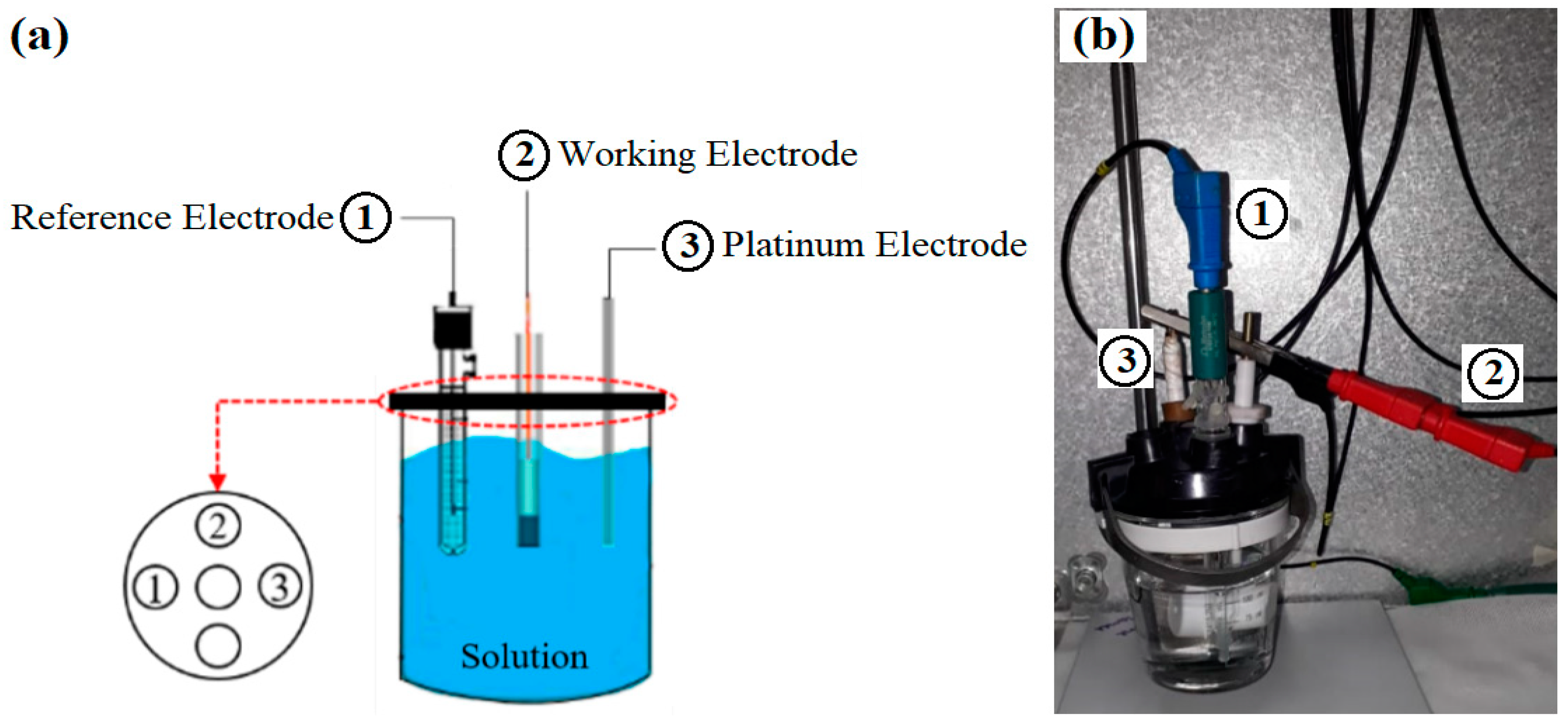
2. Materials and Methods

The composition of the shape memory stainless steel (SMSS) ingot used in this work is Fe-0.009% C-8.26% Mn-5.25% Si-12.8% Cr-5.81% Ni-11.84% Co (% by weight). It was produced by vacuum induction melting (VIM). The ingot was hot forged into a bar of Ø = 5 mm. This bar was solution treated (ST) at 1050 °C for 40 min and then quenched in water at room temperature. After solution annealing, the bar was cold rotation annealed to approximately 4 mm ap, resulting in an area reduction (AR) of 20% (ST + AR 20%), consisting of a deformed material to induce precipitation during heat treatment. The ST + AR 20% bar was cut into pieces (10 mm in length) and then annealed for one hour at temperatures ranging from 250 °C to 1050 °C, hereafter referred to as ST + AR 20% + 250; ST + AR 20% + 350; ST + AR 20% + 450; ST + AR 20% + 550; ST + AR 20% + 650; ST + AR 20% + 750; ST + AR 20% + 850; ST + AR 20% + 950 and ST + AR 20% + 1050. Table 1 summarizes the acronyms used in the samples examined in this work.
For the microstructural observations, hardness test and corrosion test, the samples were prepared using conventional metallographic procedures: grinding and polishing. To reveal the microstructure, the specimens, except those for corrosion tests, were etched in a solution of 3 mL HCl + 2 mL glycerin + 1 mL HNO3. Microstructural characterization was performed using a TESCAN VEGA3 (TESCAN, Brno–Kohoutovice, Czech Republic) scanning electron microscope (SEM) equipped with an energy dispersive spectroscopy (EDS) system.
The hardness measurements of the samples were performed in a Vickers hardness tester (Future-Tech FM-700, Kawasaki, Japan) with a load of 1.96 N/15 s. Ten measurements were made for each sample in the longitudinal section.
The martensitic transformation temperature was investigated using a Netzsch DSC404C Pegasus differential scanning calorimeter (Netzch, Selb, Germany). The thermal analyzers were used at a scanning rate of 10 °C/min, while the thermal cycle used in the samples was cooling to −130 °C followed by heating to 300 °C. For the DSC analyses, the samples were cut in a low-speed cutter, model Isomet Low-Speed Saw (Buehler, Lake Bluff, IL, USA), to obtain a sample with a mass of approximately 40 mg. Two measurements were made for each sample.
To analyze the corrosion resistance, an electrochemical test was performed on the samples. In this step, potentiodynamic polarization curves were determined in 3.5% NaCl solutions to verify the anodic behavior in an acidic medium. This solution is intended to simulate a saline environment, as applications such as pipe couplings may be exposed to this type of atmosphere. A conventional electrochemical cell with three electrodes (reference electrode, working electrode and platinum electrode), as shown in Figure 1, was used to perform the test. The working electrodes were represented by samples (the working electrode area is 7 mm2); the reference electrode was silver chloride, and the counter electrode was platinum. The test was performed using the Autolab potentiostat/galvanostat (Metrohm, Herisau, Switzerland). The parameters used were carried out through the open circuit potential, selecting the potentiostat mode of the instrument= with high stability and a stabilization time of 300 s, then starting the potential variation from 0.25 V to −0.25 V at a rate of 0.001 V/s in steps of 0.001 V.

3. Results

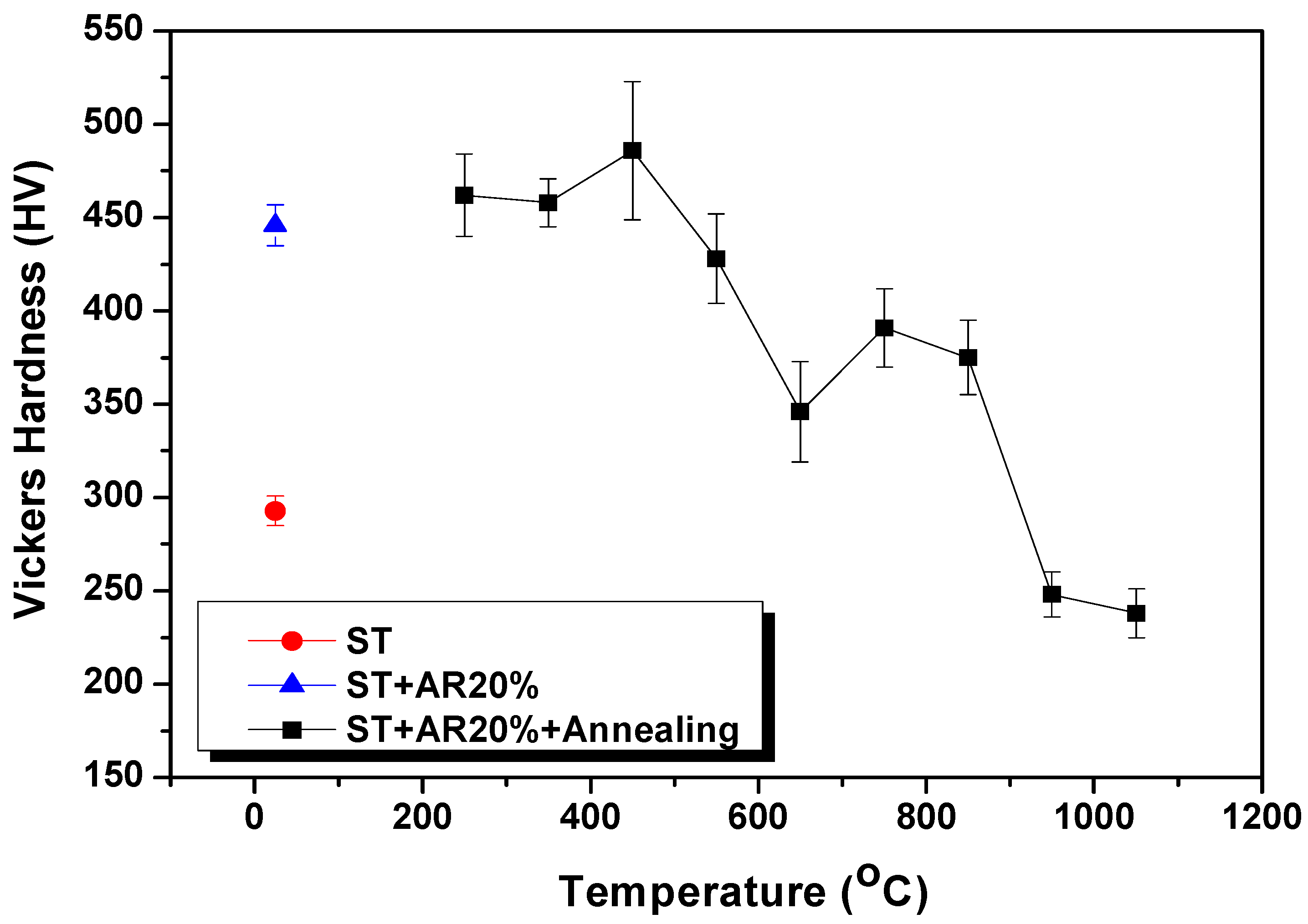
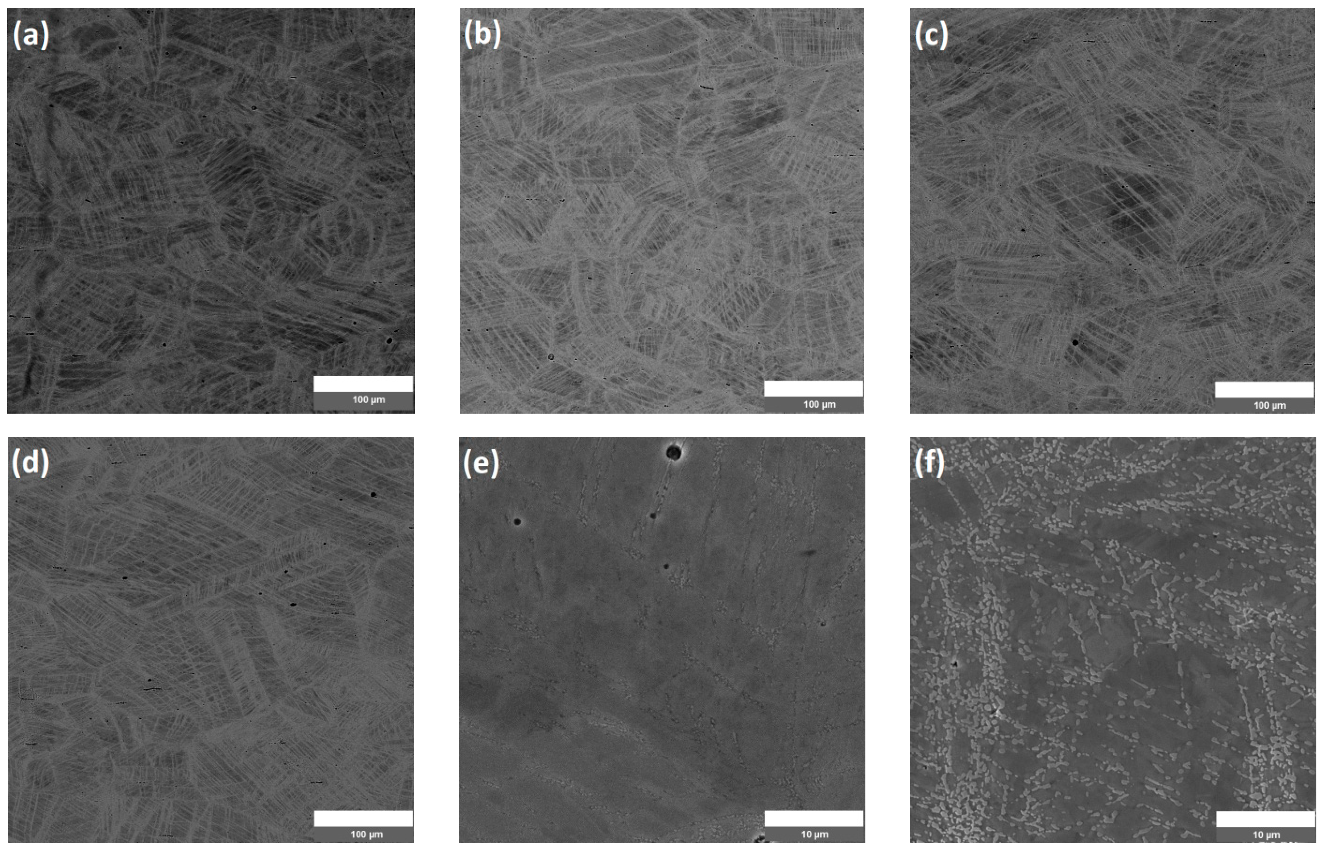
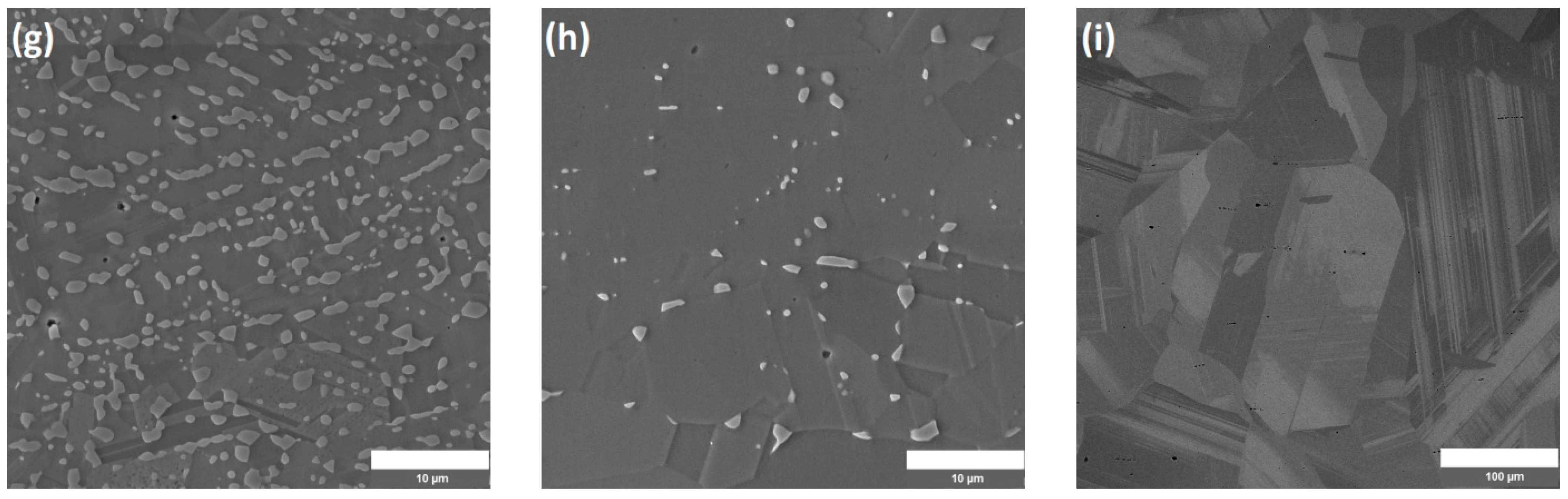
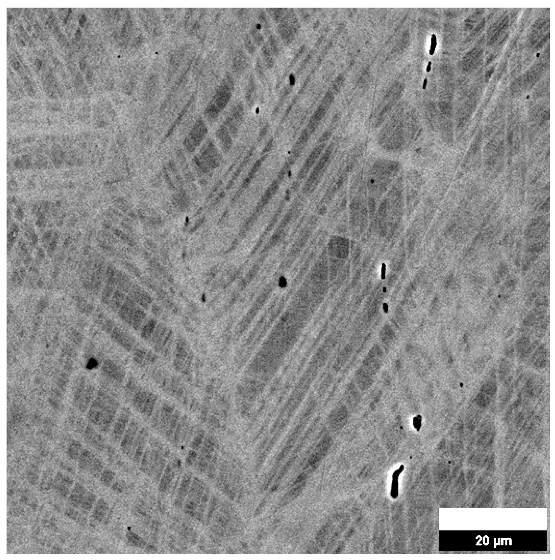
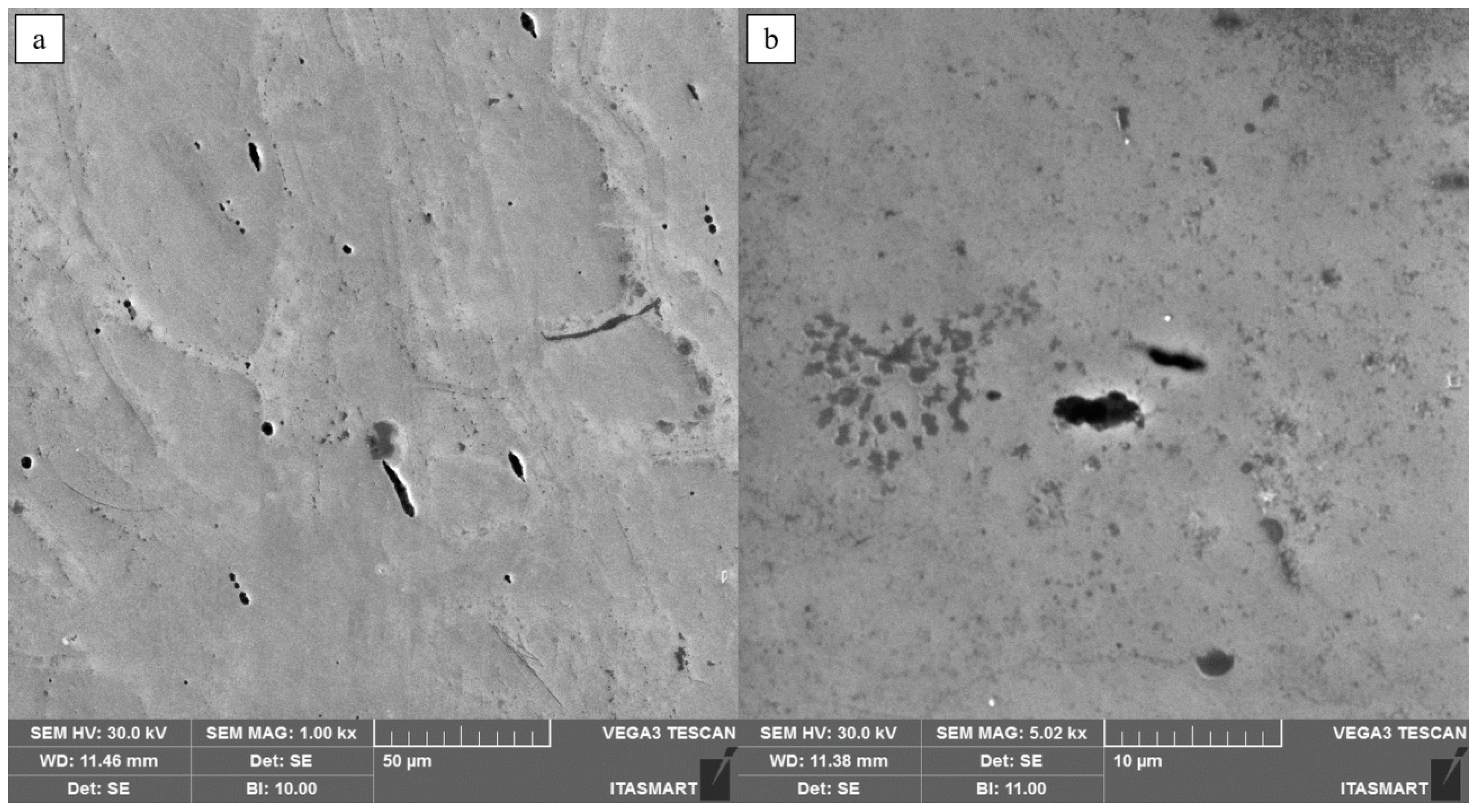
3.1. Microstructural Evolution

In order to evaluate the effect of heat treatment on the microstructural features such as a second-phase particle, a detailed characterization of samples under different processing conditions was performed as follows: ST; ST + AR 20% and ST + AR 20% + annealing temperature. Figure 2 shows the hardness values with error bars (standard deviation calculated from ten measurements per sample) as a function of sample conditions.
The effect of cold rotary swaging could be seen by an increase in hardness from 257 ± 8 HV (ST) to 447 ± 16 HV after 20% AR (ST + 20% AR) due to the work hardening effect. One hour annealing from 250 °C to 450 °C shows a slight increase in hardness (~50 HV) and then a decrease up to 950 °C. Up to a temperature of 450 °C, no significant change in hardness is observed in this material, but when the error bars are considered, a heterogeneity of values is observed. Therefore, it is assumed that the mechanism occurring in the sample up to this temperature is the recovery of the microstructure. Between 450 °C and 850 °C, there is a decrease in hardness (around 114 HV), and above 850 °C a pronounced softening of the material is observed, indicating recrystallization. On the other hand, a decrease in hardness between 450 °C and 650 °C can initially be associated with the appearance of the second phase (450 °C) followed by its coalescence (650 °C), but this phenomenon competes with the recrystallization process, so a second softening in hardness is observed (650–850 °C).
The onset of grain growth occurs at 950 °C, where the hardness values are stabilized, and at 1050 °C annealing (238 ± 13 HV) the hardness returns to the value of the solution-treated sample (before deformation)—that is, 257 ± 8 HV (ST).
To understand the behavior of the hardness during the annealing process of the samples, it is necessary to evaluate the microstructures formed after the deformation process and at each heat treatment temperature.
The microstructural evolution of the FeMnSiCrNiCo-based SMSS after annealing is shown in Figure 3, where it is possible to verify the microstructural changes that occur during the heat treatments. At temperatures ranging from 250 °C to 550 °C (Figure 3b–d), no visible microstructural change is observed and the microstructures are similar to the just deformed state (Figure 3a).
Andrade et al. [7] studied SMSSs based on FeMnSiCrNiCo that were processed by cold drawing and observed an increase in the hardness of the material at 550 °C, with AR = 57% due to the second stage of precipitation particles. In the case of the material studied, no precipitates were observed up to this temperature, but at 450 °C there is a slight increase in hardness from 447 ± 16 HV (deformed state) to 486 ± 37 HV (annealed state). This may be related to the size of the precipitates, which are in the submicron range and are in agreement with the matrix, making them difficult to visualize by scanning electron microscopy (SEM).
Samples annealed at 650 °C to 950 °C (Figure 3e–h) show the precipitation of nodular precipitates. At 850 °C, it is possible to observe the coalescence of the precipitates, and EDS analyses show that these precipitates are mainly enriched in chromium (Cr) and silicon (Si); thus, the micrographs observed corroborate the hardness values, showing that the slight increase in this property mechanics at 450 °C may also be related to the appearance of this new phase. Since the stainless alloy studied in this work has a higher number of alloying elements, the precipitation and coalescence of a second phase can occur mainly due to the heat treatment at high temperatures. As seen in the literature by Käfer et al. [8], samples with composition and weight similar to the present work have been analyzed, and the obtained results show the precipitates enriched in Cr and Si to the austenitic matrix (χ phase particles); it was further discussed by the authors that the formation of precipitates rich in Cr and Si could increase the mechanical resistance of the matrix.
The sample annealed at 1050 °C (Figure 3i) has a microstructure with a second phase completely dissolved in the matrix and austenitic grains of the order of 100 µm.

3.2. Phase Transformation

The variations in heat flow allowed the determination of the temperature at which the reversion of martensite to austenite begins (As) and the temperature at which the transformation of martensite to austenite by heating ends (Af), as shown in Table 2. Values related to enthalpies (ΔH) are also shown.
No reverse martensitic transformation peak temperatures associated with transformation (ε → γ) were observed for other sample conditions during DSC measurements. This could be due to the amount of volumetric fraction of martensitic phase present in these samples or due to the lower transformation temperature, which is not detected by this technique. Only the solution-treated sample showed a transformation peak (Ms) associated with the γ → ε transformation at −25 °C.
The transformation temperature results are presented for four conditions only, since no peak was observed in the other samples during the DSC measurements.
It is noted that the average values of As and Af are close to 121 °C and 144 °C, respectively. Dong et al. [18], who studied hot-rolled FeMnSiCrNiCo with a similar composition, found an As temperature of 110 °C.
It is also possible to observe that there was a decrease in the transition temperature (As and Af) as well as an increase in the transformation energy (ΔH), i.e., a greater volume transformed. Deformed specimens, when subjected to annealing treatments, have reduced defects; therefore, they do not interfere with the reversal of martensite. Gu et al. [24] suggested that the high annealing time/temperature could reduce the obstacles that hindered the motion of partial dislocations, and, thus, an increase in ∆H would be expected.
On the other hand, an opposite behavior is observed in FeMnSiCr-Ni-Co based SMSSs, where there is an increase in ∆H at 850 °C (according to [24]) and a decrease in ∆H at 950 °C e 1050 °C. At 850 °C, which may be associated with precipitate boundaries that act as regions for nuclear martensite plates, these may also be incoherent precipitates with the matrix, facilitating the movement of partial displacements. When the temperature is increased to 1050 °C, ∆H decreases, which is not expected according to [24]. The annealing temperature leads to a reduction in the number of partial displacements involved in the phase transformation, which may reduce the value of ∆H.

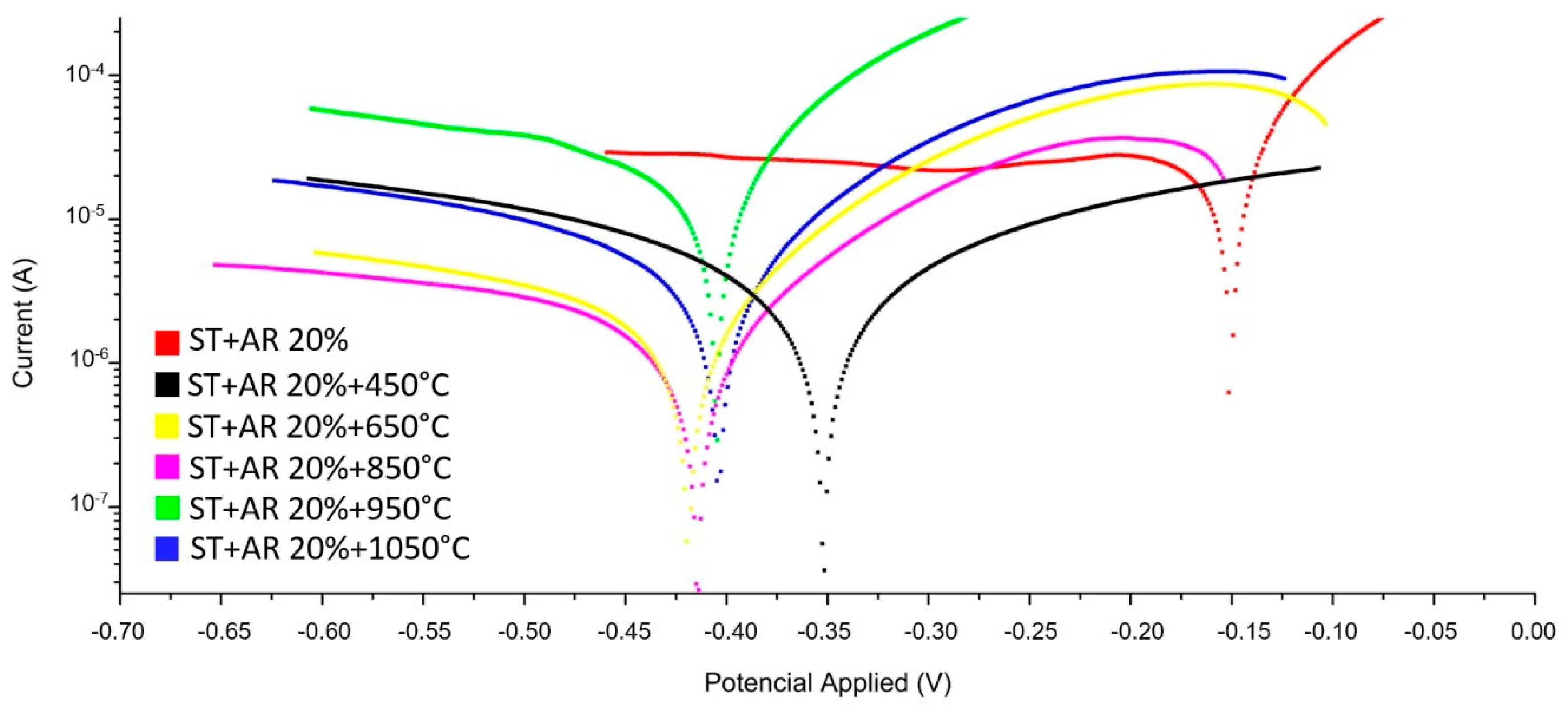
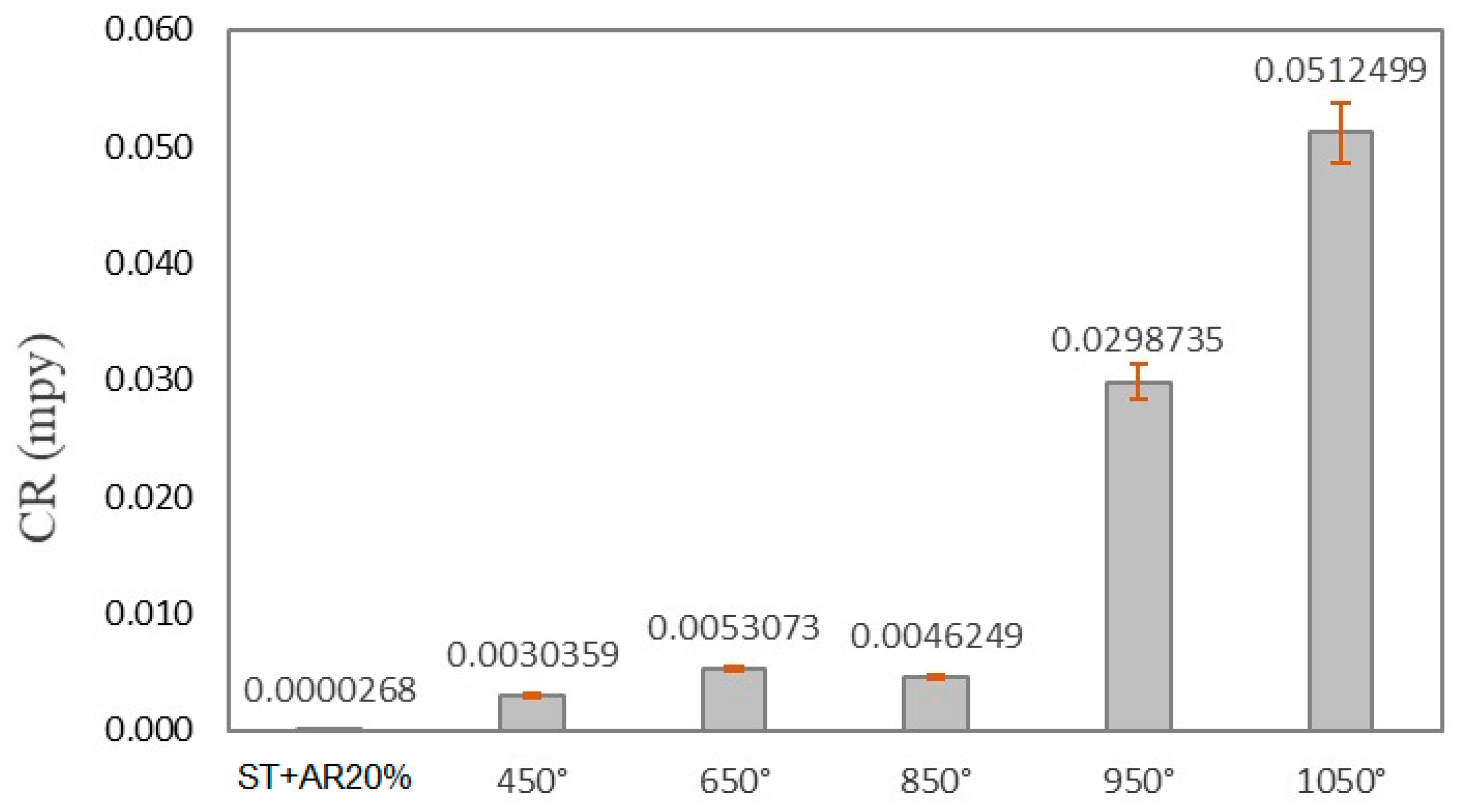
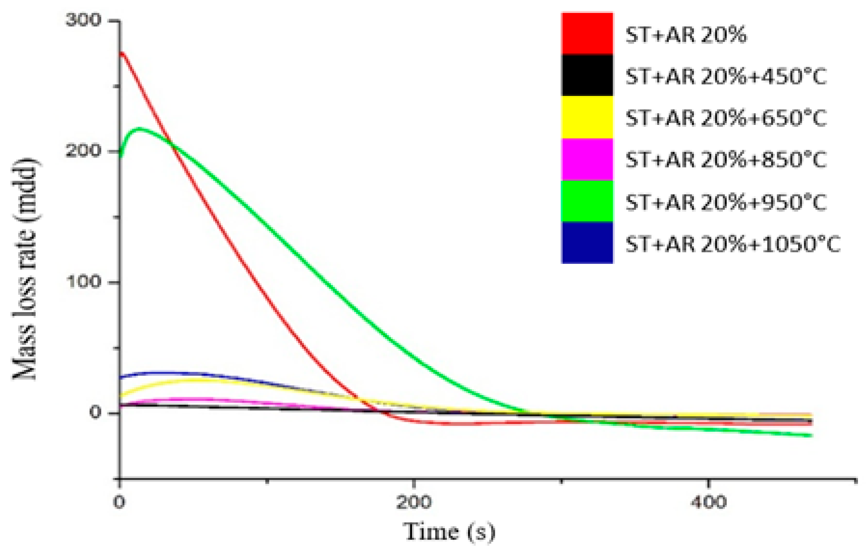
3.3. Corrosion Resistance

The result of the corrosion analysis in the deformed and annealed SMSS based on FeMnSiCrNiCo is shown in Figure 4. It is possible to observe the polarization of the material through the Taffel analysis plots. These temperature ranges are chosen because they refer to the onset of precipitation (450 °C) and continue with the coalescence of the precipitates (650 °C to 950 °C) until their dissolution (1050 °C).
It can be seen that the corrosion potentials of the samples subjected to heat treatments are similar to each other, except for the samples ST + 20%AR + 450 °C which have lower values than the others. This factor indicates that the samples subjected to annealing at 650 °C, 850 °C, 950 °C and 1050 °C are more active in 3.5% NaCl than the samples in the deformed state and at 450 °C. This event may be influenced by the presence of precipitate in 650–1050 °C samples, since second particles are enriched in Si and Cr (χ phase particles) in this material [8] and, therefore, the matrix is depleted of chromium and susceptible to corrosion due to phase coalescence. The presence of residual stresses in this case does not seem to have much influence on the deformed and annealed sample at 450 °C due to the low percentage of cold work (AR = 20%).
The results of the corrosion potential (Ecorr) are in good agreement with the literature by Della Rovere et al. [13], who presented the Ecorr of −0.340 V for FeMnSiCrNiCo solution treatment in a 3.5% NaCl solution. The corrosion potential obtained in this study presents the range of −0.150 V to −0.410 V for the same alloy and composition in a 3.5% NaCl solution. The variation in the results may be due to a decrease in Cr or an increase in Mn, or the presence of precipitates in the material. It is known that the lower the corrosion potential value, the greater the tendency of the material to corrode.
Table 3 shows the values of corrosion potential (Ecorr), corrosion current density (icorr) and corrosion rate (CR) obtained from linear polarization curves in 3.5% NaCl solution and calculations according to ASTM G102 [25]. These results complement the analysis and study of the FeMnSiCrNiCo-based SMSSs. The CR data from Table 3 are shown in Figure 5.
In addition to the corrosion potential, it can be seen from Table 3 that the current density has a difference of one to two orders of magnitude greater when comparing the deformed state values to the other conditions, indicating that this state causes the most active alloy at 3.5% NaCl [3] and, in turn, results in lower corrosion rate values.
In general, it can be observed that the corrosion rate values are very low and significantly different from those found in the literature in different solutions [12], which indicates that this alloy subjected to different heat treatments has greater corrosion resistance in highly oxidizing environments. The alloys have the following order of CR according to the thermal condition 1050 °C > 950 °C > 850 °C > 650 °C > 450 °C > deformed state.
Figure 6 shows the mass loss rate, expressed in mass loss per unit area per unit time, in this case milligrams per dm² per day (mdd), and calculated like the corrosion rate using ASTM G102-89 [25]. It can be seen that the mass loss increases with time and that the 20% deformed and 950 °C alloys have a greater mass loss compared to the other alloys. However, at a certain point the rates stabilize and remain similar to each other.
Analyzing the corrosion resistance of the SMSSs based on FeMnSiCrNiCo subjected to thermomechanical treatments and comparing it with the literature, it is expected that the sample in the deformed state would present lower resistance since the presence of martensite can reduce the corrosion resistance [19]. However, the electrical resistivity of the martensite phase is greater than that of the austenite phase, which would explain why the sample in the deformed state has better corrosion resistance [20]. With the heat treatment, there was a precipitation of a phase rich in Cr and Si (χ phase) that reduces the corrosion resistance, but annealing at 1050 °C would be expected to improve this characteristic, which does not occur when compared to samples in the deformed state. Although the presence of the second phase is not noticed in Figure 3i, the temperature/time may not have been sufficient to homogenize the alloy, which occurs in regions susceptible to corrosion, resulting in a lower Ecorr compared to the sample in the deformed state.
Due to the possible replacement of high-cost NiTi alloys by FeMnSiCrNi(Co-Ti) alloys in applications, a comparison of corrosion resistance via the shape memory effect is necessary. Andrade et al. [7] studied SMSSs based on FeMnSiCrNiCo processed by cold drawing (AR = 57) and observed an improvement in SME at 850 °C, and the same behavior was observed by Kafer et al. [8] in FeMnSiCrNiCoTi alloys after two ECAE passes and annealed at 950 °C. Therefore, a combination of plastic deformation followed by annealing can improve both SME and corrosion resistance in SMSSs based on FeMnSi alloys.
After the corrosion tests, SEM analyses were performed to observe the microstructure of SMSSs based on FeMnSiCrNiCo. The microstructures shown after the corrosion test are the samples ST + AR20%, ST + AR20% + 450 and ST + AR20% + 650. The samples annealed at 850 °C, 950 °C and 1050 °C do not show significant changes compared to the samples annealed at 650 °C, so the micrographs are not shown. This could be because the Ecorr is very close to these samples and the corrosion is similar.
In the ST + AR20% sample (solution-treated sample and deformed in an area reduction of 20%) shown in Figure 7, no severe corrosion attack was observed; this is due to its greater resistance to corrosion in NaCl solution. The analyses confirm the previously presented results due to the similarity to the deformed state before the corrosion test (Figure 3a).
Figure 8 shows the samples in the annealed condition at temperatures of 450 °C (Figure 8a) and 650 °C (Figure 8b), which showed different results from the deformed sample, indicating that these conditions are susceptible to corrosion.
Since the results presented in Della Rovere et al. [11] are very similar to those obtained here, it can be said that, as in the literature, the alloys presented a high pitch density due to the presence of precipitates in the alloy microstructure. These precipitates were formed due to the increase in Mn content and acted as nucleation sites in the corrosion process, mainly by pitting [26,27].

4. Conclusions

In this study, the influence of precipitates on the corrosion resistance of a FeMnSiCrNiCo-based SMSS was evaluated. Through the analysis of the results obtained, it is concluded that the FeMnSiCrNiCo alloy shows nodular precipitates enriched mainly with Si and Cr. However, these precipitates are located only at the grain boundaries during the annealing process, causing a slight increase in hardness at 450 °C.
Samples annealed at 450 °C have better corrosion resistance compared to other annealing conditions. It is well known that the lower the corrosion potential value, the greater the tendency of the material to corrode. Another factor influencing corrosion resistance is the nature of the precipitates formed. In this condition, no precipitates were observed in the microstructure, but the hardness values indicate their presence. On the other hand, the morphology of the precipitates can influence the corrosion resistance.
The corrosion rate graphs, based on the ASTM G102 standard, showed results that differed significantly from those found in the literature, indicating that this alloy, subjected to different heat treatments, has greater corrosion resistance in highly oxidizing environments.
The mass loss graph, based on the ASTM G102 standard, showed that the mass loss rate for 20% deformed alloys heat treated at 950 °C is quite high compared to other alloys.

Author Contributions

Conceptualization, S.S.L.M., R.d.C.M.S.-C. and H.H.B.; methodology, S.S.L.M., R.d.C.M.S.-C. and H.H.B.; validation, S.S.L.M., R.d.C.M.S.-C. and H.H.B.; formal analysis, S.S.L.M., R.d.C.M.S.-C. and H.H.B.; resources, H.H.B. and J.O.; data curation, S.S.L.M., R.d.C.M.S.-C. and H.H.B.; writing—original draft preparation, S.S.L.M.; writing—review and editing, R.d.C.M.S.-C. and H.H.B.; visualization, R.d.C.M.S.-C., H.H.B. and J.O.; funding acquisition, H.H.B. and J.O. All authors have read and agreed to the published version of the manuscript.

Funding

This research was partially funded by Brazilian National Council for Scientific and Technological Development (CNPq), grant numbers 800213/2018-1 and 501077/2012-0.

Data Availability Statement

Not applicable.

Acknowledgments

ITA: INPE, and IEAv institutes for providing the equipment used during the processes.

Conflicts of Interest

The authors declare no conflict of interest.

References

  1. Li, H.; Dunne, D.; Kennon, N. Factors influencing shape memory effect and phase transformation behavior of Fe–Mn–Si based shape memory alloys. Mater. Sci. Eng. A 1999, 273–275, 517–523. [Google Scholar] [CrossRef]
  2. Otubo, J.; Mei, P.R.; Koshimizu, S. Production and characterization of stainless steel based Fe-Cr-Ni-Mn-Si(-Co) shape memory alloys. J. Phys. IV Fr. 1995, 5, C8–C427. [Google Scholar] [CrossRef]
  3. Otsuka, H.; Yamada, H.; Maruyama, T.; Tanahashi, H.; Matsuda, S.; Murakami, M. Effects of alloying additions on Fe-Mn-Si shape memory alloys. ISIJ Int. 1990, 30, 674–679. [Google Scholar] [CrossRef]
  4. Kajiwara, S.; Liu, D.; Kikuchi, T.; Shinya, N. Remarkable improvement of shape memory effect in Fe-Mn-Si based shape memory alloys by producing NbC precipitates. Scr. Mater. 2001, 44, 2809–2814. [Google Scholar] [CrossRef]
  5. Baruj, A.; Kikuchi, T.; Kajiwara, S.; Shinya, N. Improvement of shape memory properties of NbC containing Fe–Mn–Si based shape memory alloys by simple thermomechanical treatments. Mater. Sci. Eng. A 2004, 378, 333–336. [Google Scholar] [CrossRef]
  6. Wei, Z.; Li, N.; Wen, Y.; Huang, S.K. Grain refinement and carbide precipitation in Fe–Mn–Si–Cr–Ni–C shape memory alloy fabricated by equal channel angular pressing. Mater. Sci. Technol. 2010, 26, 691–694. [Google Scholar] [CrossRef]
  7. Andrade, E.C.; Bernardi, H.H.; Otubo, J. Microstructural evaluation on shape recovery in stainless Fe-Mn-Si-Cr-Ni-Co SMA processed by wire drawing. Mater. Res. 2014, 17, 583–587. [Google Scholar] [CrossRef]
  8. Käfer, K.A.; Bernardi, H.H.; Santos, O.D.S.; Otubo, L.; Lima, N.B.D.; Otubo, J. The Influence of Microstructure and Mechanical Resistance on the Shape Memory of Ecae Processed Stainless Fe-Mn-Si-Cr-Ni-Co Steel. Mater. Res. 2018, 21, e20170958. [Google Scholar] [CrossRef]
  9. Motzki, P.; Seelecke, S. Industrial Applications for Shape Memory Alloys. Encycl. Smart Mater. 2022, 4, 254–266. [Google Scholar] [CrossRef]
  10. Li, J.C.; Lu, X.X.; Jiang, Q. Shape memory effects in a Fe14Mn6Si9Cr5Ni alloy for joining pipe. ISIJ Int. 2000, 40, 1124–1126. [Google Scholar] [CrossRef]
  11. Della Rovere, C.A.; Alano, J.H.; Silva, R.; Nascente, P.A.P.; Otubo, J.; Kuri, S.E. Characterization of passive films on shape memory stainless steels. Corros. Sci. 2012, 57, 154–161. [Google Scholar] [CrossRef]
  12. Della Rovere, C.A.; Alano, J.H.; Otubo, J.; Kuri, S.E. Corrosion behavior of shape memory stainless steel in acid media. J. Alloys Compd. 2011, 509, 5376–5380. [Google Scholar] [CrossRef]
  13. Della Rovere, C.A.; Alano, J.H.; Silva, R.; Nascente, P.A.P.; Otubo, J.; Kuri, S.E. Influence of alloying elements on the corrosion properties of shape memory stainless steels. Mater. Chem. Phys. 2012, 133, 668–673. [Google Scholar] [CrossRef]
  14. Silva, R.; Vacchi, G.S.; Santos, I.G.R.; de Sousa Malafaia, A.M.; Kugelmeier, C.L.; Mendes Filho, A.A.; Pascal, C.; Sordi, V.L.; Rovere, C.A.D. Insights into high-temperature oxidation of Fe-Mn-Si-Cr-Ni shape memory stainless steels and its relationship to alloy chemical composition. Corros. Sci. 2020, 163, 108269. [Google Scholar] [CrossRef]
  15. Silva, R.; Arana, C.; de Sousa Malafaia, A.M.; Mendes Filho, A.A.; Pascal, C.; Otubo, J.; Sordi, V.L.; Rovere, C.A.D. Microstructure and surface oxidation behavior of an austenitic Fe-Mn-Si-Cr-Ni-Co shape memory stainless steel at 800° C in air. Corros. Sci. 2019, 158, 108103. [Google Scholar] [CrossRef]
  16. Rabelo, L.F.P.; Silva, R.; Della Rovere, C.A.; Sousa Malafaia, A.M. Metal/oxide interface roughness evolution mechanism of a FeMnSiCrNiCe shape memory stainless steel under high-temperature oxidation. Corros. Sci. 2020, 163, 108228. [Google Scholar] [CrossRef]
  17. Dias, D.; Nakamatsu, S.; Della Rovere, C.A.; Otubo, J.; Mariano, N.A. Characterization and corrosion resistance behavior of shape memory stainless steel developed by alternate routes. Metals 2020, 10, 13. [Google Scholar] [CrossRef]
  18. Dong, Z.Z.; Liu, W.X.; Wang, D.F.; Chen, J.M.; Liu, D.Z. A study of the corrosion resistance and shape memory effect of FeMnSiCrNiCo shape-memory alloy. Mater. Sci. Forum 2001, 394–395, 435–438. [Google Scholar] [CrossRef]
  19. Zhu, X.; Zhang, Y. Effect of ε-martensite on the electrochemical corrosion behavior of Fe-Mn-Si shape memory alloy in aqueous solutions. J. Mater. Sci. Lett. 1997, 16, 1516–1517. [Google Scholar] [CrossRef]
  20. Charfi, A.; Bouraoui, T.; Feki, M.; Bradai, C.; Normand, B. Surface treatment and corrosion behavior of Fe-32Mn-6Si shape memory alloy. Comptes Rendus Chim. 2009, 12, 270–275. [Google Scholar] [CrossRef]
  21. Ma, R.; Peng, H.; Wen, Y.; Zhang, L.; Zhao, K. Oxidation behavior of an austenitic stainless FeMnSiCrNi shape memory alloy. Corros. Sci. 2013, 66, 269–277. [Google Scholar] [CrossRef]
  22. de Sousa Malafaia, A.M.; Latu-Romain, L.; Wouters, Y. Initial stages of FeMnSiCrNi shape memory stainless steels oxidation mechanism at 800°C. Corros. Sci. 2021, 181, 109255. [Google Scholar] [CrossRef]
  23. Jiao, Y.; Zhang, H.; Wen, Y. Influence of temperature on the oxidation behaviour of an austenitic stainless FeMnSiCrNi shape memory alloy. Oxid. Met. 2019, 92, 109–121. [Google Scholar] [CrossRef]
  24. Gu, Q.; Van Humbeeck, J.; Delaey, L. Effect of annealing on the martensitic transformation in Fe-Mn-Si stainless steel. In Proceedings of the Symposium on Functional Material and Energy Source Science for Young Scientists, Shanghai, China, 1992; p. 131. Available online: https://lirias.kuleuven.be/1751672 (accessed on 19 April 2021).
  25. ASTM G102-89; G102: Standard Practice for Calculation of Corrosion Rates and Related Information from Electrochemical Measuraments, Reaproved. American Society for Testing and Materials (ASTM): West Conshohocken, PA, USA, 1994.
  26. Knustsenball, R.D.A. The influence of inclusions on the corrosion behavior of a 12 wt% chromium steel. Corros. J. Sci. Eng. 1997, 47, 359–368. [Google Scholar] [CrossRef]
  27. Ryan, M.; Williams, D.E.; Chater, R.J.; Hutton, B.M.; Mcphail, D.S. Whys stainless steel corrodes. Nature 2002, 415, 770–774. [Google Scholar] [CrossRef] [PubMed]
Figure 1. (a) Schematic view of the conventional electrochemical cell with three electrodes; (b) real view of the conventional electrochemical cell with three electrodes.
Alloys 02 00008 g001
Figure 2. Effect of annealing temperature on the hardness of samples.
Alloys 02 00008 g002
Figure 3. Microstructure of the SMSSs based on FeMnSiCrNiCo in the (a) deformed state and annealed condition at the temperatures of (b) 250 °C, (c) 450 °C, (d) 550 °C, (e) I 650 °C, (f) 750 °C, (g) 850 °C, (h) 950 °C and (i) 1050 °C.
Alloys 02 00008 g003aAlloys 02 00008 g003b
Figure 4. Tafel graph in 3.5% NaCl solution for SMSSs based on FeMnSiCrNiCo.
Alloys 02 00008 g004
Figure 5. The corrosion rate in 3.5% NaCl solution for SMSSs based on FeMnSiCrNiCo.
Alloys 02 00008 g005
Figure 6. The mass loss rate in 3.5% NaCl solution for SMSSs based on FeMnSiCrNiCo.
Alloys 02 00008 g006
Figure 7. Microstructure of the SMSS based on FeMnSiCrNiCo in the deformed state after corrosion tests.
Alloys 02 00008 g007
Figure 8. Microstructure of the SMSSs based on FeMnSiCrNiCo in the annealed condition at the temperatures of (a) 450 °C and (b) 650 °C.
Alloys 02 00008 g008
Table 1. Acronyms were used to identify the samples.
SampleDescription
SMSSShape memory stainless steel
STSolution treated
ST + AR20%Solution-treated sample and deformed in an area reduction of 20%
ST + AR 20% + 250Solution-treated sample and deformed in an area reduction of 20%, and annealed in 250 °C
ST + AR 20% + 350Solution-treated sample and deformed in an area reduction of 20%, and annealed at 350 °C
ST + AR 20% + 450Solution-treated sample and deformed in an area reduction of 20%, and annealed at 450 °C
ST + AR 20% + 550Solution-treated sample and deformed in an area reduction of 20%, and annealed at 550 °C
ST + AR 20% + 650Solution-treated sample and deformed in an area reduction of 20%, and annealed at 650 °C
ST + AR 20% + 750Solution-treated sample and deformed in an area reduction of 20%, and annealed at 750 °C
ST + AR 20% + 850Solution-treated sample and deformed in an area reduction of 20%, and annealed at 850 °C
ST + AR 20% + 950Solution-treated sample and deformed in an area reduction of 20%, and annealed at 950 °C
ST + AR 20% + 1050Solution-treated sample and deformed in an area reduction of 20%, and annealed at 1050 °C
Table 2. Values of the transition temperature of the SMSSs based on FeMnSiCrNiCo.
ConditionEnthalpyTransition Temperature (°C)
ΔH (J/g)AsAf
ST0.50122.4151.5
ST + AR 20% + 8501.42128.9157.5
ST + AR 20% + 9500.71115.6133.8
ST + AR 20% + 10500.71116.4132.1
Table 3. Corrosion potential, current density and corrosion rate values obtained by the linear polarization method in 3.5% NaCl solution (* mpy: milli-inch per year).
ConditionEcorr (V)Icorr (µA/cm²)CR (mpy) *
ST + 20%AR−0.1506.91 × 10−52.68 × 10⁻⁵
ST + 20%AR + 450−0.3538.0 × 10−33.03 × 10⁻³
ST + 20%AR + 650−0.4171.4 × 10−25.31 × 10⁻³
ST + 20%AR + 850−0.4161.2 × 10−24.62 × 10⁻³
ST + 20%AR + 950−0.4067.7 × 10−22.98 × 10⁻²
ST + 20%AR + 1050−0.4101.32 × 10−15.12 × 10⁻²
Disclaimer/Publisher’s Note: The statements, opinions and data contained in all publications are solely those of the individual author(s) and contributor(s) and not of MDPI and/or the editor(s). MDPI and/or the editor(s) disclaim responsibility for any injury to people or property resulting from any ideas, methods, instructions or products referred to in the content.

