Article

Additive Manufacturing of MnAl(C)-Magnets

1
Department of Chemistry—Ångström Laboratory, Uppsala University, Box 523, 75120 Uppsala, Sweden
2
Höganäs AB, Bruksgatan 35, 26333 Höganäs, Sweden
*
Author to whom correspondence should be addressed.
Alloys 2023, 2(2), 100-109; https://doi.org/10.3390/alloys2020007
Submission received: 19 March 2023 / Revised: 2 May 2023 / Accepted: 5 May 2023 / Published: 15 May 2023
(This article belongs to the Special Issue Design of New Metallic Alloys for AM)

Abstract

:
Permanent magnets are becoming more and more relevant for modern society. As the most widely used permanent magnets contain rare-earth elements, the increased dependence on these strategic elements is worrisome, and the pursuit for rare-earth free alternatives has become a strategic goal in many countries. The metastable and ferromagnetic τ-phase that forms in the MnAl(C) system is one of the most promising alternatives, and since its discovery, major efforts have been made to improve its performance and realize its full potential. One major factor that has prevented a widespread commercialization of MnAl(C) permanent magnets is their relatively low coercivity. Here, we demonstrate that additive manufacturing, using laser powder bed fusion, can be used to produce MnAl in its high-temperature polymorph (ε, hcp), which can be subsequently transformed, through post-heat treatments to the ferromagnetic τ-phase. Although we successfully obtained a preferential orientation of the ε-phase with <001> parallel to the build direction, this did not translate into a strong preferential orientation in the τ-phase, thus indicating that the phase transformation occurs by the migration of incoherent interfaces. The MnAl(C) samples are characterized by a density of ≈4.4 g/cm3, a saturation magnetization of 39.3 Am2/kg, a coercivity of 168 kA/m, and a remanence of 17.5 Am2/kg.

1. Introduction

Permanent magnets are critically important for many applications and industries that sustain modern societies. Consumer electronics, the automotive and medical industries, among others, have a high and increasing demand for permanent magnets [1,2]. The performance of permanent magnets is often described using the energy product (BH)max, which is a measure of the magnetic flux density that can be stored in the material [2]. The most common permanent magnet systems used are Nd-Fe-B and hard ferrites (MFe12O19, with M being Ba or Sr), which have energy products around 470 kJ/m3 [1] and 38 kJ/m3 [1], respectively. There are many concerns around the production of Nd-Fe-B magnets, as the supply of rare-earth elements is concentrated in a few countries, posing a potential threat for their availability in the future. Therefore, the development of new rare-earth free permanent magnets is considered a priority in many countries [3]. One alternative is hexagonal ferrites, which are low-cost, and contain elements that are readily available. However, a large gap exists between the performance (energy product) of Nd-Fe-B and ferrites. The MnAl(C) system contains a ferromagnetic phase (τ) [4], that, in theory, has the characteristics (energy density of ≈112 kJ/m3 [1]) to fill this gap. However, one of the limitations of MnAl(C) is its typically low coercivity (meaning a resistance to changes in magnetization), which is a prime requirement for a hard magnet.
Coercivity is a magnetic property that can be improved by controlling the extrinsic factors (not related to the chemical composition) that hinder the movement of the magnetic domains. Particles of secondary phases (precipitates or impurities) and crystallographic texture [5,6] have been found to be some of the extrinsic mechanisms that can increase the coercivity in MnAl(C) magnets. In the case of the crystallographic texture, a similar alignment of the grains in a polycrystalline material (and thus, similar alignment of the directions of easy magnetization) can make the rotation of the magnetic moments more difficult, thus requiring a stronger magnetic field to demagnetize the material, i.e., with a higher coercivity [6]. Here, additive manufacturing processes, such as laser powder bed fusion (LPBF) could play a major role, as the laser scan strategy and printing parameters can be used to influence the microstructure [7] and crystallographic texture [8] during the printing process. For instance, White et al. [9] previously demonstrated that the laser engineered net shaping method can be used to produce Alnico magnets with improved magnetic properties (remanence, intrinsic coercivity, and energy product) in comparison to sintered parts. Although this was partially attributed to the formation of columnar grains with strong texture, no formal analysis of the preferential orientation was conducted in that study. On the other hand, the potential of AM-related texture for the enhancement of the magnetic properties in Nd-Fe-B has been previously recognized [10], but in recent trials with LPBF, no significant texture could be inferred from the remanence of the samples [11], or from their X-ray diffraction (XRD) patterns [12].
In the case of the MnAl(C) system, recent trials have been performed with powder bed fusion methods, such as electron beam melting (EBM) [10,13] and laser powder bed fusion (LPBF) [14]. The as-printed samples produced by EBM were composed mainly of the thermodynamically stable and non-magnetic γ2 phase in combination with smaller fractions of ε and τ (with only 8 wt% of the latter). Nevertheless, a high fraction of τ-phase (>90 wt%) was obtained with a combination of high-temperature heat treatment at 1100 °C, followed by annealing procedures at 500 °C [13]. The main focus of that study was the optimization of the production parameters, and the heat treatments to obtain dense parts with a high fraction of τ-phase and texture was mostly overlooked. For the parts manufactured with LPBF [14], ε was the main phase observed in the as-printed parts, with some amounts of γ2, β, and minor amounts of the τ-phase. Interestingly, in that investigation, the characteristic growth of the dendrites (lacking secondary arms) was pointed out as an indication of crystallographic texture.
In this work, we demonstrate that LPBF can be used to produce MnAl(C) in its high-temperature polymorph (ε-phase), with a strong alignment of the <002> directions parallel to the build direction. The effect of a textured ε-phase on the formation and orientation of the τ-phase was investigated after the heat treatments.

2. Materials and Methods

The samples were produced using an EOS M100 system with gas atomized MnAl(C) powder provided by Höganäs AB. The chemical composition of the powder can be found in Table A1, and it should be noted that the composition of the powder was intentionally Mn-rich to balance any potential Mn-evaporation that occurred during laser melting. Initially, a wide process window of the process parameters was investigated. The best stability of the parts was obtained using a relatively low laser power with a re-melting step at each layer (see Figure 1a). These parameters were obtained through process parameter development experiments, in which the effect of different laser powers, scan speeds, and hatch spacing were investigated. Based on these results, cylindrical samples were then produced using a narrower set of parameters with a laser power between 18–25 W, speed between 160 and 240 mm/s, 70 μm of hatch spacing, 20 μm layer thickness, and 5 mm of hatch length.
The samples were characterized using X-ray diffraction (XRD) with a Bruker D8 Advance Diffractometer (Cu Kα) and a Bragg-Brentano experimental setup. Optical microscopy was performed with a Zeiss Axio Imager A2m microscope. A Hitachi SU6600 equipped with an Electron Back Scattering Diffraction detector (Oxford Symmetry Camera) was used for scanning electron microscopy (SEM) and electron backscattered diffraction (EBSD) analysis. The density of the samples was estimated using the Archimedes principle and pycnometry (AccuPyc II 1340). Heat treatments were conducted by sealing the samples under vacuum in quartz tubes (to avoid oxidation) and then heating with a rate of 10 °C/min. Once the temperature of interest was reached, the samples were held for 5 min followed by quenching in water. The samples used for the magnetic measurements (∽diameter of 10 mm × height of 4 mm) were annealed using a flash heating procedure for 30 min under vacuum. The magnetic measurements were performed using an M-meter from Epping GmbH with an applied maximum field of 1.5 T.

3. Results and Discussion

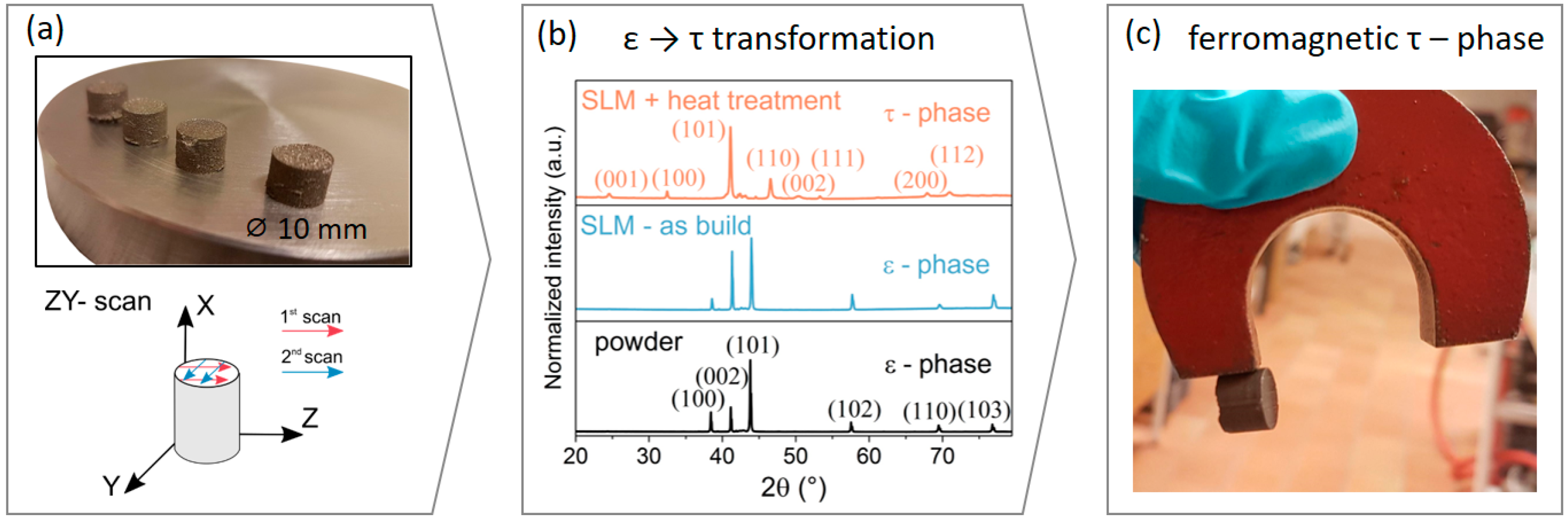
An image of the as-printed LPBF samples can be seen in Figure 1a. The laser scan strategy implemented, with a double exposure at each layer is also illustrated. 
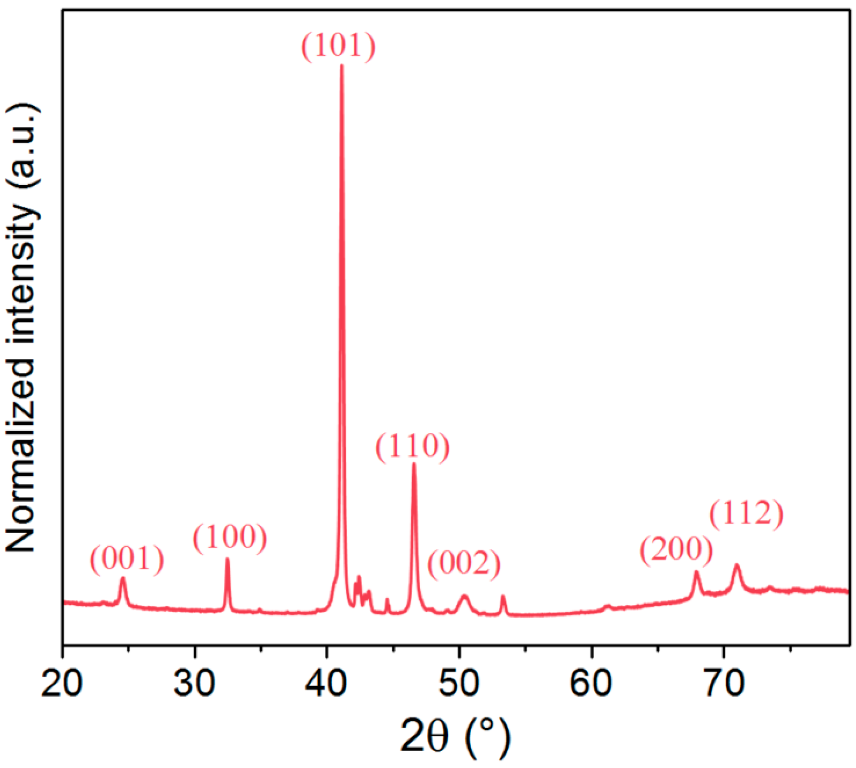
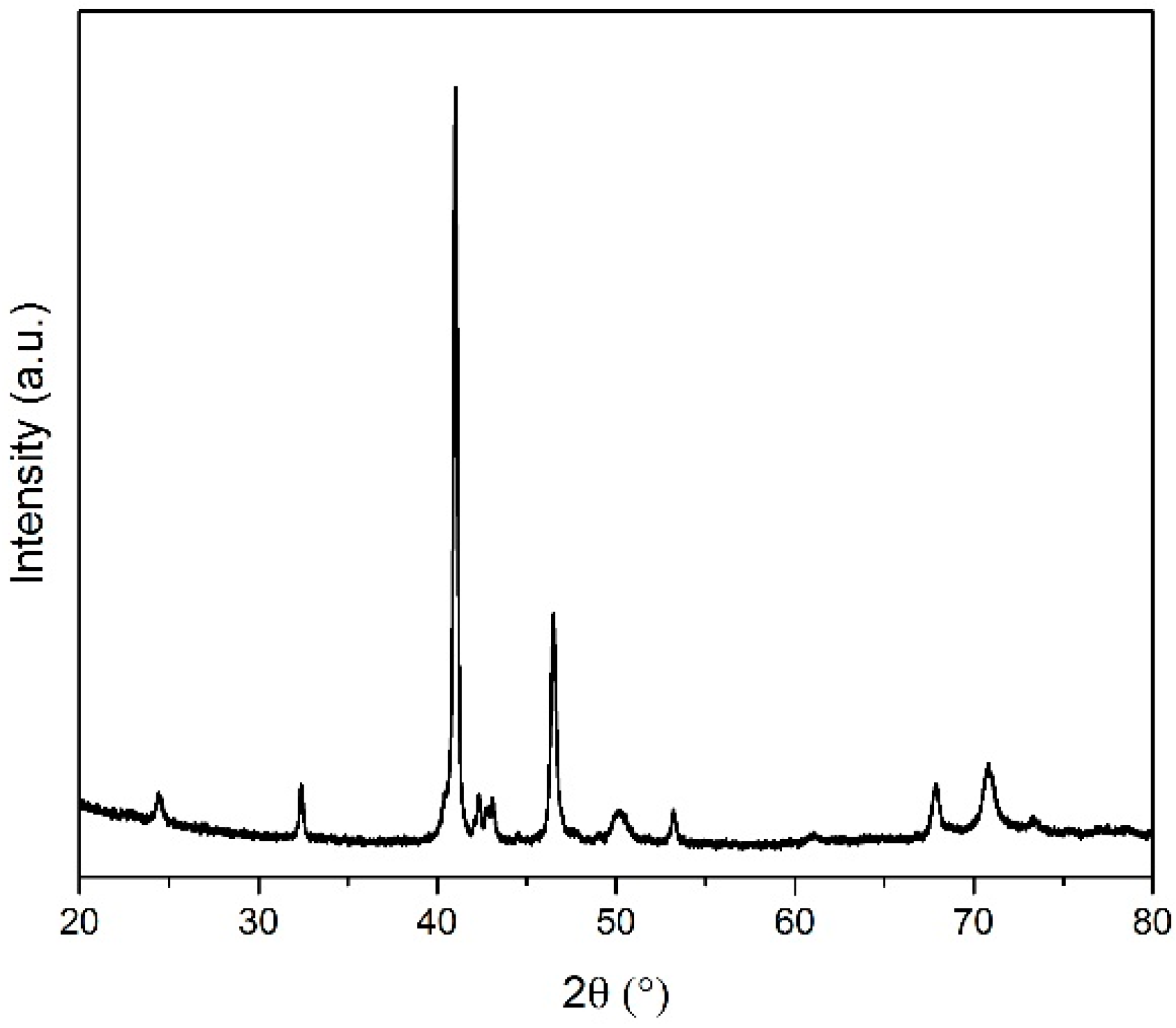
Figure 1b shows the XRD patterns of the raw powder and the as-printed and heat-treated parts. The XRD patterns indicate that both the raw powder and the as-printed samples contain mainly the hexagonal ε-phase, with small amounts of the γ2 phase. The presence of a large fraction of the ε-phase is in good agreement with previous reports in MnAl(C) parts [14]. The critical cooling rate to retain the ε-phase has been estimated to be around 20 K/s [15]. Thus, it is not surprising that the rate of cooling during the printing process (≈100 K/s [16]) was enough to retain the high-temperature polymorph.
An interesting feature of the diffraction patterns of the as-build parts in Figure 1b, is the increased intensity of the (002) reflection. This was clearly observed when comparing the black (powder) and blue (LPBF) diffractograms in Figure 1b and reveals a preferential orientation (texture) of the <002> directions parallel to the build direction. The increased texture seems to be correlated with the specific laser scan-strategies and parameters, as variations were observed through the samples produced with different parameters and scan-strategies. Heat treatments were conducted at 580 °C during 5 min to promote the transformation from the ε- to the τ-phase. The diffraction pattern after this annealing procedure (Figure 1b) indicates a high fraction of the ferromagnetic τ-phase. Here, it is relevant to mention that a small fraction of secondary phases was also observed, as illustrated in Figure A1 of the Appendix A. These phases, present in small fractions, correspond to the stable γ2, Mn3AlC, and β phases.
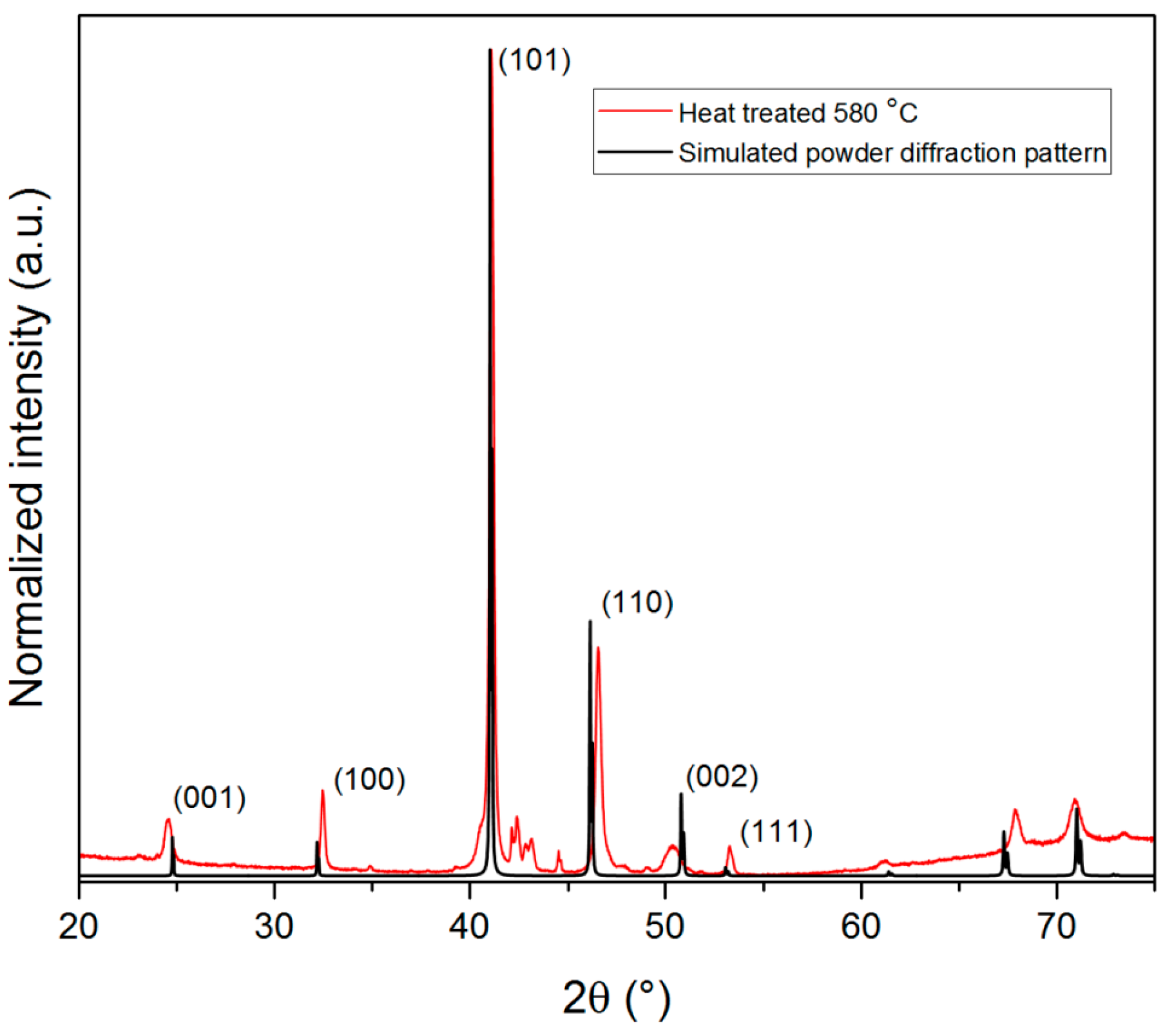
Our initial expectation was that the strong (002) preferential orientation in the ε-phase would translate to a textured τ-phase, in accordance with orientation relationships between the ε- and τ-phases described in the literature [17,18,19,20]. For instance, Kojima et al. [18] observed that during the annealing of an ε-phase single crystal, the transformation sequence ε (hexagonal) → ε’ (orthorhombic) → τ (tetragonal) occurs, with the crystallographic relations (0001)ε || (100)ε’ || (111)τ. Similar relations were proposed by Jakubovics et al. [19]. These crystallographic relations were proposed for the τ-phase with unit cell parameters around a = 3.9 Å and c = 3.6 Å [18] (the τ-phase can be described with 2 different tetragonal unit cells). In the present work, we used the unit cell with parameters around a = 2.8 Å and c = 3.6 Å [21]. The (111)τ planes in the first reference system were equivalent to the (101)τ in the latter. Thus, a strong alignment of the <101> directions with the build direction should be present in the τ-phase. Conversely, the formed τ-phase does not exhibit a significant preferential orientation, as evidenced by the comparison with the simulated XRD pattern for this phase (Figure A2).
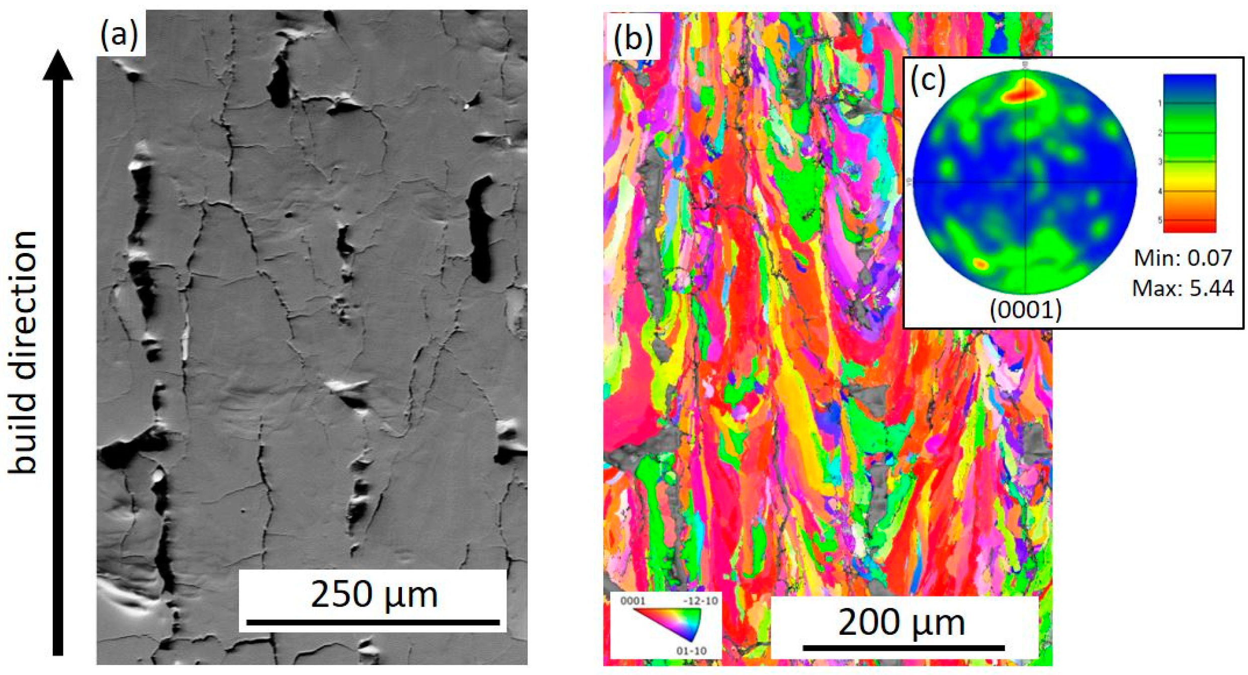
The XRD patterns from 
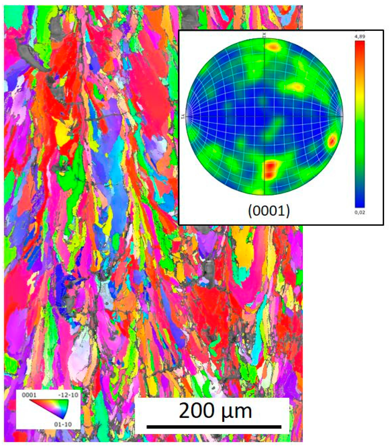
Figure 1b indicate a strong texture for the as-printed samples, but to obtain a full description of the preferential orientation of the parts, EBSD was employed, and grain orientation maps were obtained as shown in Figure 2. The pole figure for the as-printed sample suggests that the <001> directions were in parallel to the build direction (although some misalignment of the poles was also observed), which is in good agreement with the interpretation of the XRD patterns. An additional grain orientation map and (001) pole figure is shown in Figure A3, and similarly in that case, some misalignment of the poles was seen, and additionally, an extra pole was observed at an orthogonal direction.
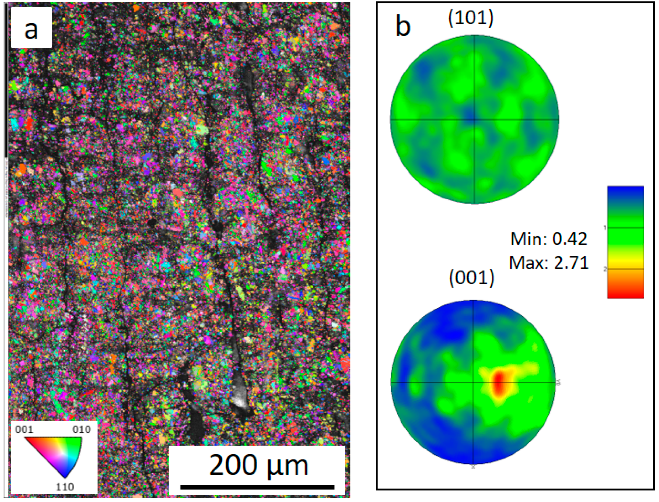
From both the XRD patterns and the EBSD, a strong crystallographic texture was identified in the ε-phase. Its effect on the formation of the τ-phase was also studied (after the heat treatments) using EBSD, as shown in Figure 3. It is evident that the texture observed in the ε-phase does not translate into the τ-phase for the present samples. It is, however, important to highlight that not all of the areas could be indexed in this case (see dark areas in Figure 3a and Figure A4). In addition to the high quantity of porosities and cracks stemming from the printing process, this could also be related to difficulties preparing the sample’s surface for EBSD. In 
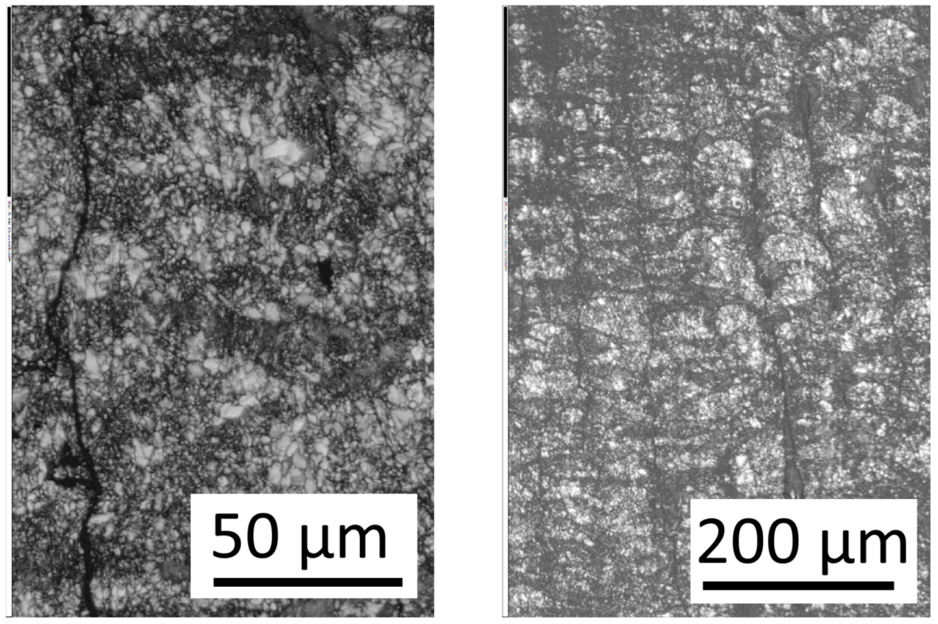
Figure 3, it can also be seen that the heat-treated material seems to have a relatively small grain size, which was expected due to the significant twinning observed during the ε- to τ-phase transition.
The lack of a preferred orientation in the grains of the τ-phase could be explained by the phase transformation mechanism proposed by Hoydik et al. [20]. In that work, it was observed that initially, each τ-phase nucleus holds a coherent relationship with a grain of the ε-phase. However, almost no growth occurs into these ε grains, and instead τ grows by consuming neighboring grains that do not hold a special crystallographic relationship with it (incoherent interfaces).
In Figure 2a and 
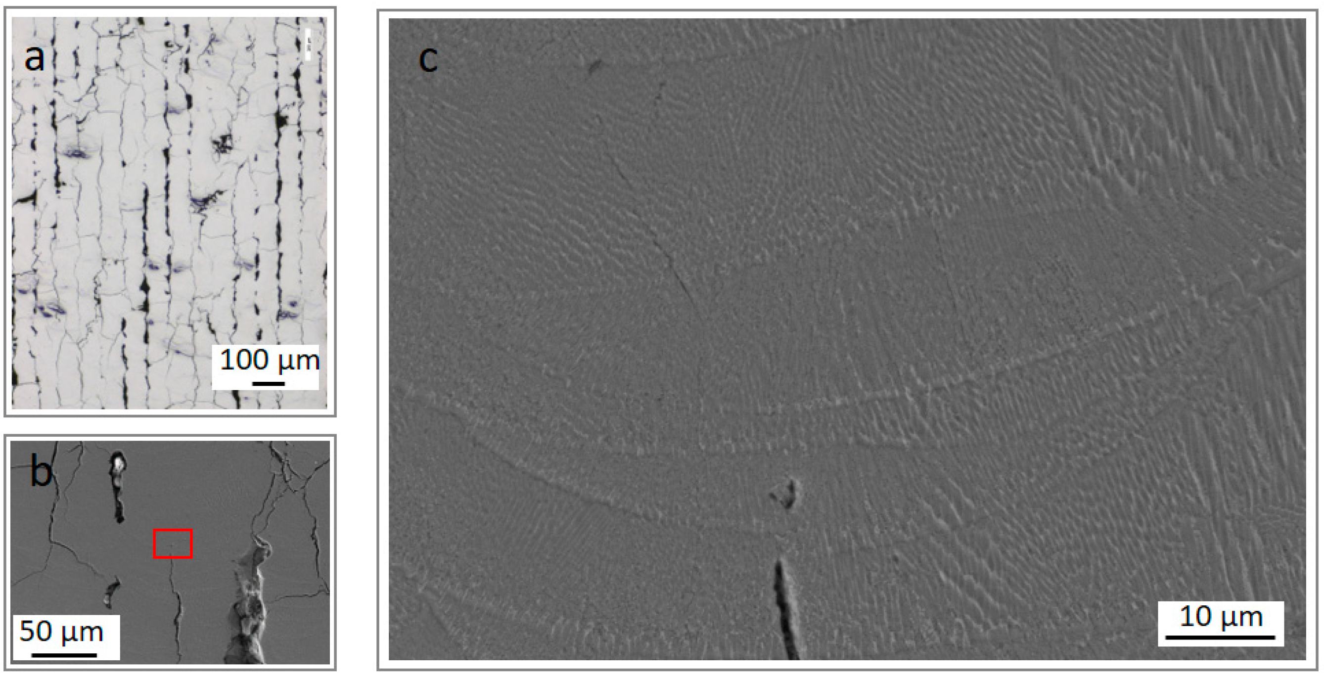
Figure 3a, a significant number of cracks and pores were observed. To further investigate their distribution, as well as to evaluate the microstructure of the LPBF parts, additional microscopy studies were conducted, as displayed in Figure 4. The observed cracks and pores are distributed throughout the specimens. A similar crack distribution, with propagation throughout the parts, was previously observed in MnAl(C) produced by LPBF [14]. The cracks seemingly originate both from the “lack of fusion”-defects [22], as well as micro-cracking caused by thermal stresses [14]. In Figure 4c, some microstructural features can be observed. The elongated structures probably correspond to dendritic microstructures. Additionally, some sort of micro-cellular structure can be identified.
The cracks and pores seen in Figure 2, Figure 3 and Figure 4 produced relatively low densities in the parts, and values around 4.5 g/cm3 (bulk density with open pores) were obtained in some of the samples evaluated. The theoretical density for the ε-phase was 5.12 g/cm3. The low density of the LPBF parts significantly limits their final performance, i.e., a high magnetization per unit mass cannot be achieved due to the many pores and cracks. To solve this issue, an alternative approach, with the use of a heating plate, will be explored in the future.
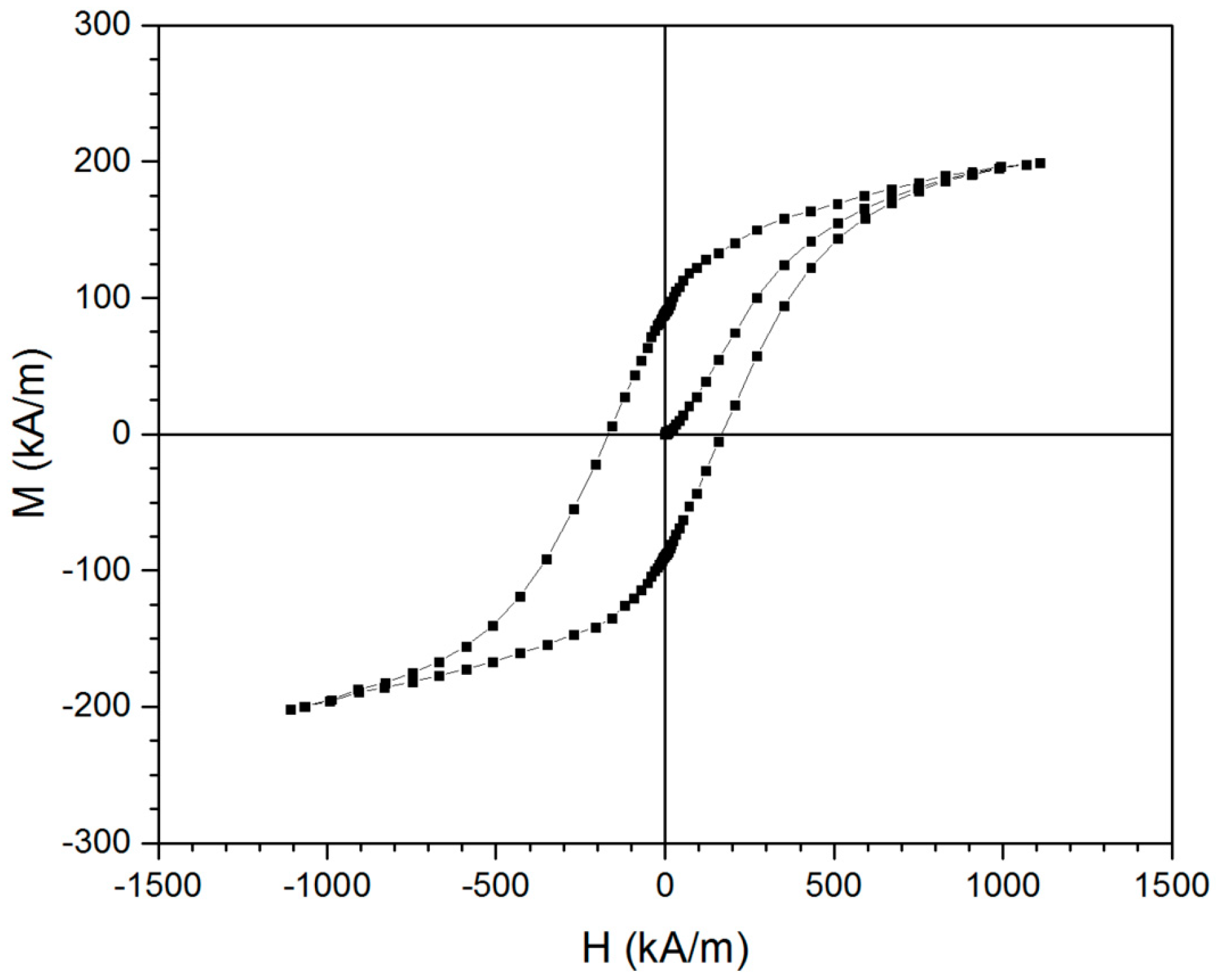
Regardless of the challenging amounts of the cracks and pores, as well as the correlated low densities, an initial characterization of the magnetic properties was conducted (after annealing by rapid heating and cooling), as shown in Figure 5. The most relevant magnetic properties are summarized in Table 1, where the values reported by Radulov et al. for the Mn53Al47 alloy produced by EBM can also be found. The corresponding XRD pattern for this sample can be seen in Figure A5.
As summarized in Table 1, the sample exhibits an Ms of 39.3 Am2/kg. This value was found to be significantly lower than the optimized values obtained in the samples produced by EBM and is deemed to be related to the presence of additional, non-magnetic phases besides the ε-phase, such as γ2, Mn3AlC, and β phases (see Figure A5). On the other hand, the coercivity of 168 kA/m was found to be higher than the 119.4 kA/m reported previously for the EBM parts. To put these values into perspective, using an optimized ball-milling procedure for (Mn55Al45)98C2, an Ms = 83 Am2/Kg, and a Hc = 222.8 kA/m have been previously obtained, respectively [21]. Therefore, further optimizations of the phase fraction and microstructure are required to improve the magnetic properties of the LPBF parts.

4. Conclusions

In this work, LPBF was used to produce MnAl(C) with a preferred orientation of the grains of the ε-phase. The strongly textured ε-phase did not translate into a preferential orientation of the τ-phase for these samples, suggesting that the ε → τ transformation occurs by the migration of incoherent interfaces. The MnAl(C) produced by LPBF in this work was characterized by a density of ≈4.4 g/cm3, a saturation magnetization of 39.3 Am2/kg, a coercivity of 168 kA/m, and a remanence of 17.5 Am2/kg, respectively. Future work should focus on the optimization of the printing parameters to obtain fully dense LPBF parts, as well as directing the texture during the ε → τ transformation. This approach, in which laser powder bed fusion was used to control the crystallographic texture, could enable the production of complex-shaped parts with a controlled magnetic performance.

Author Contributions

Conceptualization, V.P., B.S., H.V. and M.S.; formal analysis, V.P., F.O. and D.K.; investigation, V.P., D.K. and M.S.; writing—original draft preparation, V.P.; writing—review and editing, V.P., B.S., D.K., H.V. and M.S.; supervision, and M.S.; funding acquisition, M.S. All authors have read and agreed to the published version of the manuscript.

Funding

This research was funded by the Swedish Foundation for Strategic Research (SSF) within the Swedish national graduate school in neutron scattering (SwedNess, GSn15-0008), and by the Swedish Foundation for Strategic Research (SSF), through the project “SSF—Development of processes and Materials in AM”. This research was also funded by the Swedish Research Council (#2022-03069).

Data Availability Statement

All data is available upon request.

Acknowledgments

V.P. would like to thank Vitalii Shtender for the illuminating scientific discussions and suggestions.

Conflicts of Interest

The authors declare no conflict of interest.

Appendix A

Table A1. Chemical composition of the MnAl(C) powder raw material (analysis was conducted on the 10–45 µm fraction).
C (wt.%)O (wt.%)Composition (at.%)
0.7820.063(Mn60.7Al39.3)100C2.8
Figure A1. XRD pattern of the LPBF sample after the heat treatment at 580 °C for 5 min.
Alloys 02 00007 g0a1
Figure A2. Comparison of the diffractograms of XRD patterns of the LPBF sample after the heat treatment (yz cross-section) and the simulated diffraction pattern for the τ-phase.
Alloys 02 00007 g0a2
Figure A3. Grain orientation map and (0001) pole figure for an as-printed MnAl(C) sample.
Alloys 02 00007 g0a3
Figure A4. Band contrast images of a part heat treated at 580 °C during 5 min.
Alloys 02 00007 g0a4
Figure A5. XRD pattern after annealing by flash heating at 570 °C (30 min) under vacuum.
Alloys 02 00007 g0a5

References

  1. Coey, J. Permanent magnets: Plugging the gap. Scr. Mater. 2012, 67, 524–529. [Google Scholar] [CrossRef]
  2. Mohapatra, J.; Liu, J. Handbook of Magnetic Materials, 1st ed.; Elsevier B.V.: Amsterdam, The Netherlands, 2018; pp. 1–57. [Google Scholar]
  3. Kontos, S.; Ibrayeva, A.; Leijon, J.; Mörée, G.; Frost, A.; Schönström, L.; Gunnarsson, K.; Svedlindh, P.; Leijon, M.; Eriksson, S. An overview of MnAl permanent magnets with a study on their potential in electrical machines. Energies 2020, 13, 5549. [Google Scholar] [CrossRef]
  4. Palanisamy, D.; Raabe, D.; Gault, B. Elemental segregation to twin boundaries in a MnAl ferromagnetic Heusler alloy. Scr. Mater. 2018, 155, 144–148. [Google Scholar] [CrossRef]
  5. Koper, G.; Terpstra, M. (Eds.) Improving the Properties of Permanent Magnets; Springer: Dordrecht, The Netherlands, 1991. [Google Scholar]
  6. Buschow, K.; de Boer, F. Physics of Magnetism and Magnetic Materials; Springer: New York, NY, USA, 2003. [Google Scholar]
  7. Zhang, X.; Yocom, C.; Mao, B.; Liao, Y.J. Microstructure evolution during selective laser melting of metallic materials: A review. Laser Appl. 2019, 31, 031201. [Google Scholar] [CrossRef]
  8. Marattukalam, J.; Karlsson, D.; Pacheco, V.; Beran, P.; Wiklund, U.; Jansson, U.; Hjörvarsson, B.; Sahlberg, M. The effect of laser scanning strategies on texture, mechanical properties, and site-specific grain orientation in selective laser melted 316L SS. Mater. Des. 2020, 193, 108852. [Google Scholar] [CrossRef]
  9. White, E.; Rinko, E.; Prost, T.; Horn, T.; Ledford, C.; Rock, C.; Anderson, I. Processing of alnico magnets by additive manufacturing. Appl. Sci. 2019, 9, 4843. [Google Scholar] [CrossRef]
  10. Popov, V.; Koptyug, A.; Radulov, I.; Maccari, F.; Muller, G. Prospects of additive manufacturing of rare-earth and non-rare-earth permanent magnets. Procedia Manuf. 2018, 21, 100–108. [Google Scholar] [CrossRef]
  11. Bittner, F.; Thielsch, J.; Drossel, W. Laser powder bed fusion of Nd–Fe–B permanent magnets. Prog. Addit. Manuf. 2020, 5, 3–9. [Google Scholar] [CrossRef]
  12. Bittner, F.; Thielsch, J.; Drossel, W. Microstructure and magnetic properties of Nd-Fe-B permanent magnets produced by laser powder bed fusion. Scr. Mater. 2021, 201, 113921. [Google Scholar] [CrossRef]
  13. Radulov, I.; Popov, V.V.; Koptyug, A.; Maccari, F.; Kovalevsky, A.; Essel, S.; Gassmann, J.; Skokov, K.; Bamberger, M. Production of net-shape Mn-Al permanent magnets by electron beam melting. Addit. Manuf. 2019, 30, 100787. [Google Scholar] [CrossRef]
  14. Krakhmalev, P.; Yadroitsev, I.; Baker, I.; Yadroitsava, I. Manufacturing of intermetallic Mn-46% Al by laser powder bed fusion. Procedia CIRP 2018, 74, 64–67. [Google Scholar] [CrossRef]
  15. Kim, Y.; Perepezko, J. The thermodynamics and competitive kinetics of metastable τ phase development in MnAl-base alloys. Mater. Sci. Eng. A 1993, 163, 127–134. [Google Scholar] [CrossRef]
  16. Pauly, S.; Löber, L.; Petters, R.; Stoica, M.; Scudino, S.; Kühn, U.; Eckert, J. Processing metallic glasses by selective laser melting. Mater. Today 2013, 16, 37–41. [Google Scholar] [CrossRef]
  17. Van Den Broek, J.; Donkersloot, H.; Van Tendeloo, G.; Van Landuyt, J. Phase transformations in pure and carbon-doped Al45Mn55 alloys. Acta Metall. 1979, 27, 1497–1504. [Google Scholar] [CrossRef]
  18. Kojima, S.; Ohtani, T.; Kato, N.; Kojima, K.; Sakamoto, Y.; Konno, I.; Tsukahara, M.; Kubo, T. Crystal transformation and orientation of Mn-Al-C hard magnetic alloy. AIP Conference Proceedings 1975, 24, 768–769. [Google Scholar] [CrossRef]
  19. Jakubovics, J.; Jolly, T. The effect of crystal defects on the domain structure of Mn-Al alloys. Phys. B+C 1977, 86–88, 1357–1359. [Google Scholar] [CrossRef]
  20. Hoydick, D.P.; Palmiere, E.J.; Soffa, W.A. On the formation of the metastable L1 {sub o} phase in manganese-aluminum-base permanent magnet materials. Scr. Mater. 1997, 36, 151–156. [Google Scholar] [CrossRef]
  21. Fang, H.; Cedervall, J.; Casado, F.; Matej, Z.; Bednarcik, J.; Ångström, J.; Berastegui, P.; Sahlberg, M. Insights into formation and stability of τ-MnAlZx (Z = C and B). J. Alloy. Compd. 2017, 692, 198–203. [Google Scholar] [CrossRef]
  22. DebRoy, T.; Wei, H.; Zuback, J.; Mukherjee, T.; Elmer, J.; Milewski, J.; Beese, A.; Wilson-Heid, A.; De, A.; Zhang, W. Additive manufacturing of metallic components–process, structure and properties. Prog. Mater. Sci. 2018, 92, 112–224. [Google Scholar] [CrossRef]
Figure 1. (a) As-build samples and the scan strategy used to produce them. (b) X-ray diffraction patterns (λ = 1.54 Å) of the raw powder (black), LPBF as-build sample (blue), and after heat treatment at 580 °C for 5 min (orange). The XRD pattern was collected from the YZ cross section. (c) A picture of the heat-treated sample attracted to a horseshoe magnet.
Alloys 02 00007 g001
Figure 2. (a) SEM image, (b) combination of grain orientation map and band contrast, and (c) (0001) pole figure for an as-printed MnAl(C) sample. The color scheme of the grain orientation map corresponds to the orientation along the build direction (x-axis).
Alloys 02 00007 g002
Figure 3. (a) Combination of grain orientation map and band contrast and (b) pole figures for the τ-phase for a MnAl(C) sample after 580 °C during 5 min.
Alloys 02 00007 g003
Figure 4. (a) Optical microscopy and (b,c) SEM images of the as-printed samples.
Alloys 02 00007 g004
Figure 5. The hysteresis loop of a sample heat treated by flash heating at 570 °C (30 min) under vacuum.
Alloys 02 00007 g005
Table 1. Magnetic properties of the sample annealed by flash heating at 570 °C.
Density
ρ (g/cm3)
Saturation Magnetization
Ms (Am2/kg)
Coercivity
Hc (kA/m)
Remanence
Mr (Am2/kg)
4.4639.316817.5This work
5.120–100119.4 (0.15T)-Mn53Al47 by EBM [13]
Disclaimer/Publisher’s Note: The statements, opinions and data contained in all publications are solely those of the individual author(s) and contributor(s) and not of MDPI and/or the editor(s). MDPI and/or the editor(s) disclaim responsibility for any injury to people or property resulting from any ideas, methods, instructions or products referred to in the content.

