
Shifts in Product Distribution in Microwave Plasma Methane Pyrolysis Due to Hydrogen and Nitrogen Addition

Abstract
:1. Introduction
2. Results and Discussion
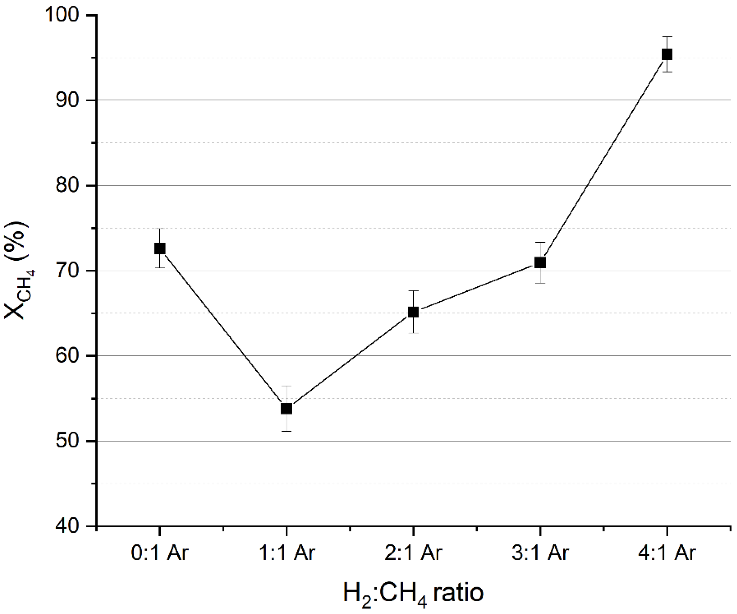
2.1. Methane Conversion
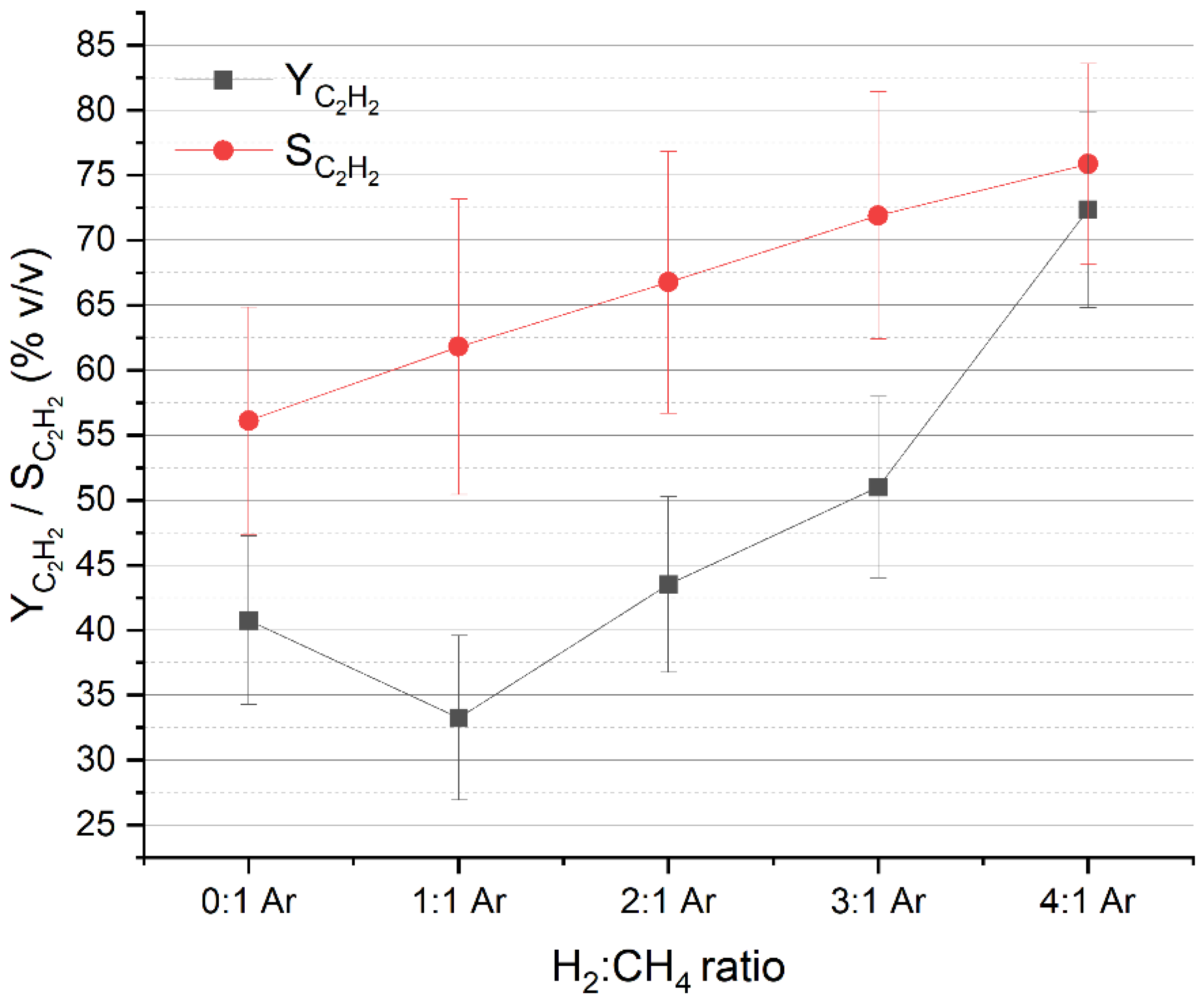
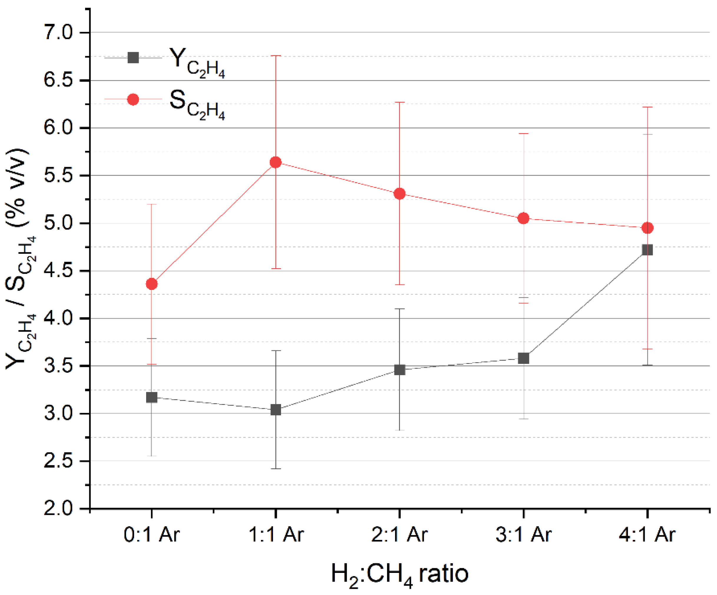
2.2. C2 Compounds Selectivity and Yield
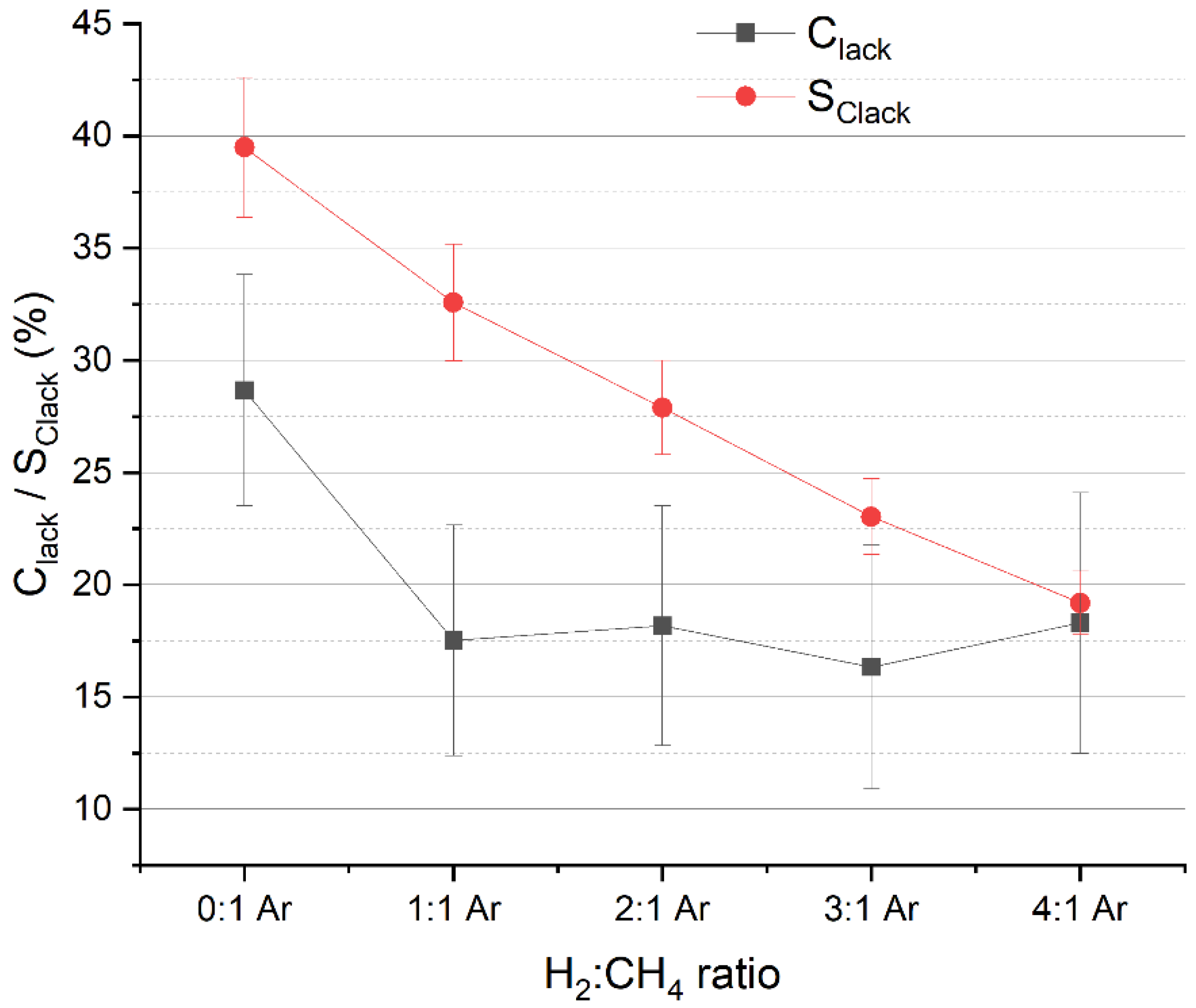
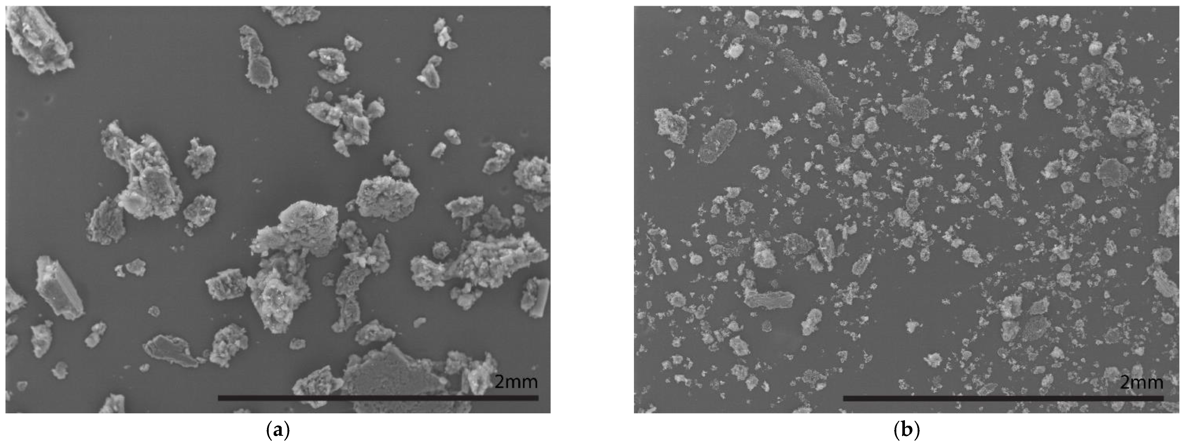
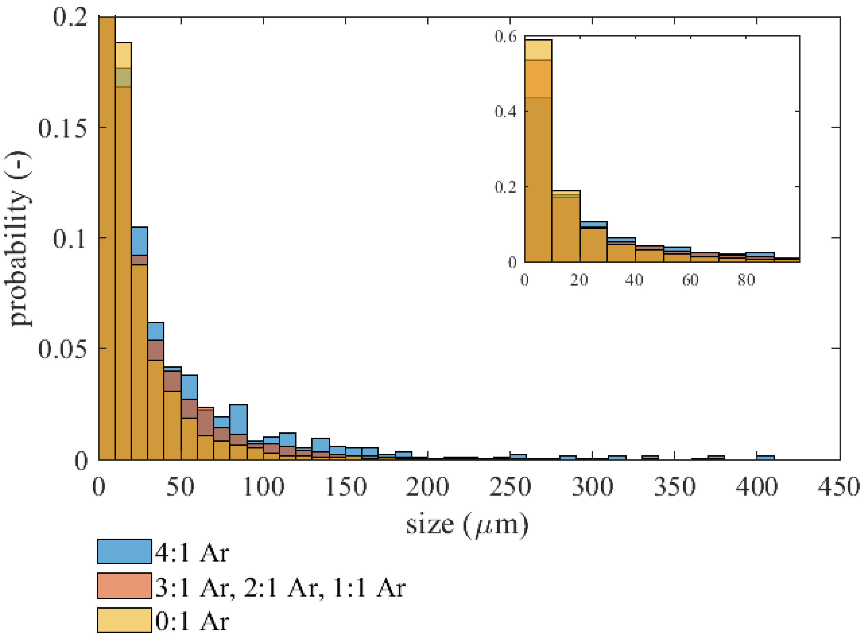
2.3. Soot
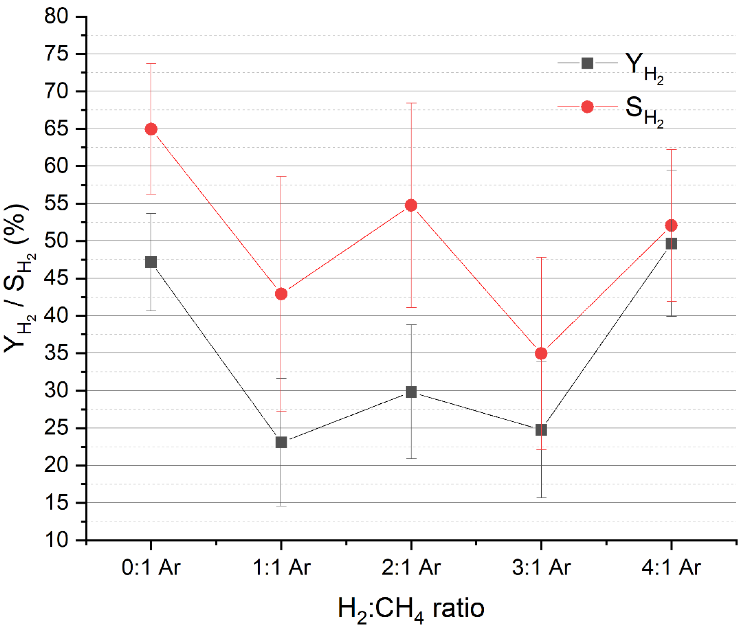
2.4. Hydrogen
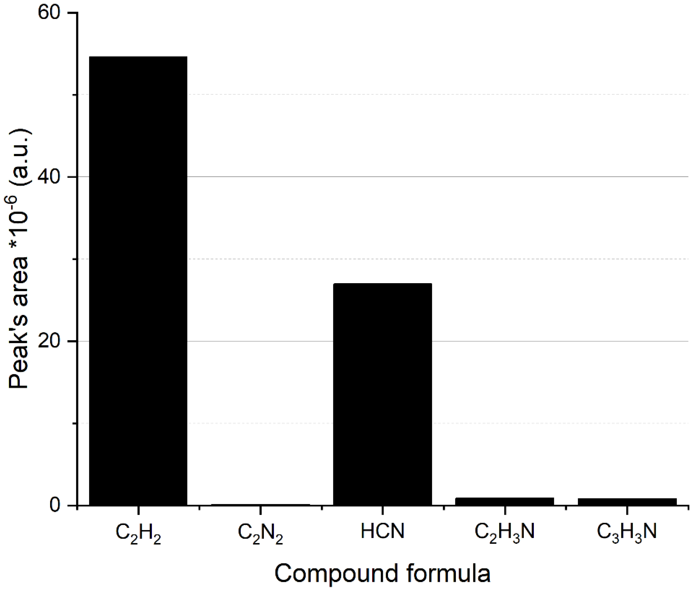
2.5. Influence of Nitrogen Addition
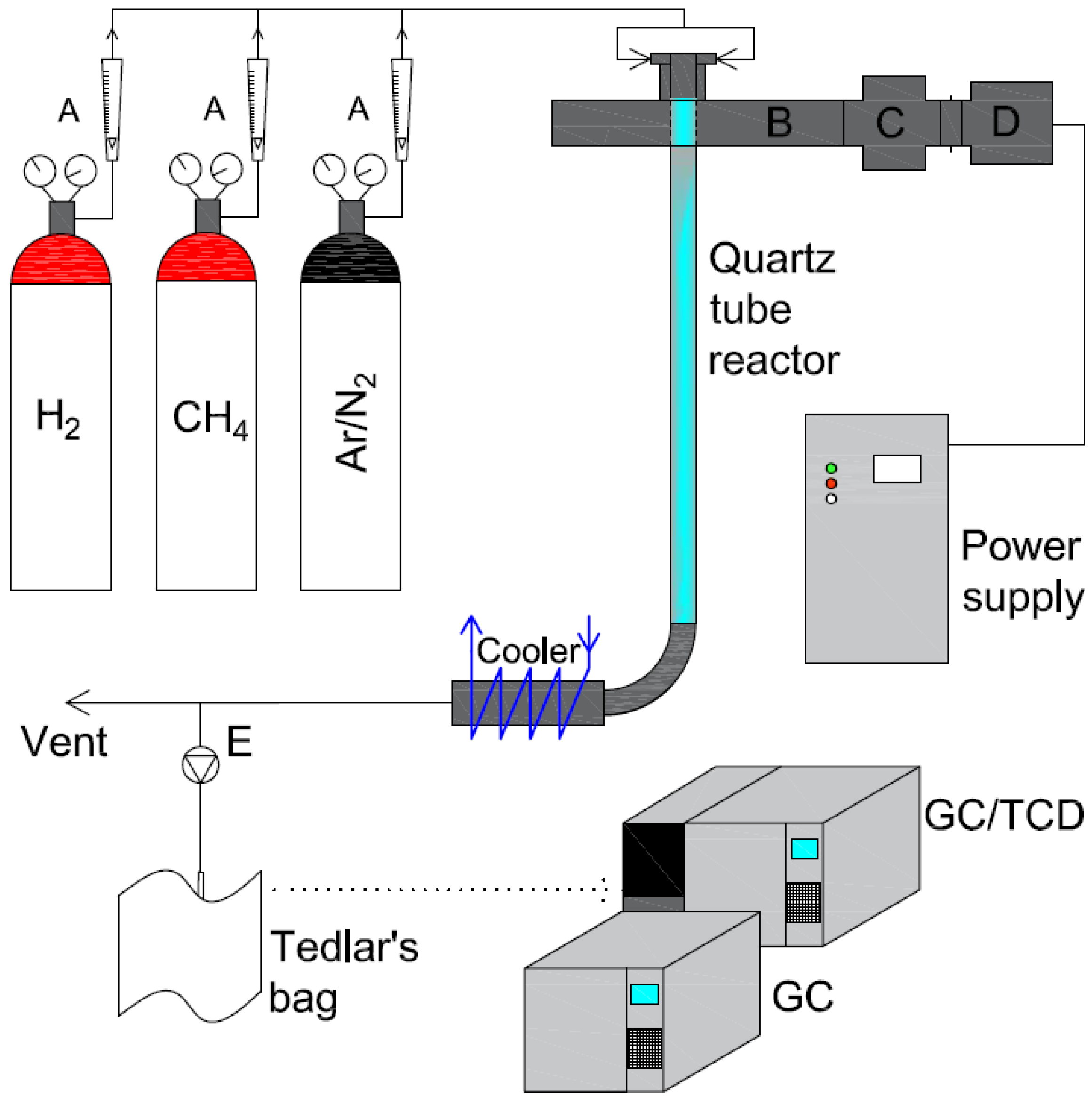
3. Materials and Methods
4. Conclusions
Author Contributions
Funding
Institutional Review Board Statement
Informed Consent Statement
Data Availability Statement
Conflicts of Interest
References
- Sánchez-Bastardo, N.; Schlögl, R.; Ruland, H. Methane Pyrolysis for Zero-Emission Hydrogen Production: A Potential Bridge Technology from Fossil Fuels to a Renewable and Sustainable Hydrogen Economy. Ind. Eng. Chem. Res. 2021, 60, 11855–11881. [Google Scholar] [CrossRef]
- Cheon, S.; Byun, M.; Lim, D.; Lee, H.; Lim, H. Parametric Study for Thermal and Catalytic Methane Pyrolysis for Hydrogen Production: Techno-Economic and Scenario Analysis. Energies 2021, 14, 6102. [Google Scholar] [CrossRef]
- Riley, J.; Atallah, C.; Siriwardane, R.; Stevens, R. Technoeconomic analysis for hydrogen and carbon Co-Production via catalytic pyrolysis of methane. Int. J. Hydrogen Energy 2021, 46, 20338–20358. [Google Scholar] [CrossRef]
- Minea, T.; van den Bekerom, D.C.M.; Peeters, F.J.J.; Zoethout, E.; Graswinckel, M.F.; van de Sanden, M.C.M.; Cents, T.; Lefferts, L.; van Rooij, G.J. Non-oxidative methane coupling to C2hydrocarbons in a microwave plasma reactor. Plasma Process. Polym. 2018, 15, 1800087. [Google Scholar] [CrossRef] [Green Version]
- Li, L.; Zeng, W.; Song, M.; Wu, X.; Li, G.; Hu, C. Research Progress and Reaction Mechanism of CO2 Methanation over Ni-Based Catalysts at Low Temperature: A Review. Catalysts 2022, 12, 244. [Google Scholar] [CrossRef]
- Msheik, M.; Rodat, S.; Abanades, S. Methane Cracking for Hydrogen Production: A Review of Catalytic and Molten Media Pyrolysis. Energies 2021, 14, 3107. [Google Scholar] [CrossRef]
- Sánchez-Bastardo, N.; Schlögl, R.; Ruland, H. Methane Pyrolysis for CO2-Free H2 Production: A Green Process to Overcome Renewable Energies Unsteadiness. Chem. Ing. Tech. 2020, 92, 1596–1609. [Google Scholar] [CrossRef]
- Heijkers, S.; Aghaei, M.; Bogaerts, A. Plasma-Based CH4 Conversion into Higher Hydrocarbons and H2: Modeling to Reveal the Reaction Mechanisms of Different Plasma Sources. J. Phys. Chem. C 2020, 124, 7016–7030. [Google Scholar] [CrossRef] [Green Version]
- Zhang, H.; Wang, W.; Li, X.; Han, L.; Yan, M.; Zhong, Y.; Tu, X. Plasma activation of methane for hydrogen production in a N2 rotating gliding arc warm plasma: A chemical kinetics study. Chem. Eng. J. 2018, 345, 67–78. [Google Scholar] [CrossRef]
- Wnukowski, M.; Jamróz, P. Microwave plasma treatment of simulated biomass syngas: Interactions between the permanent syngas compounds and their influence on the model tar compound conversion. Fuel Process. Technol. 2018, 173, 229–242. [Google Scholar] [CrossRef]
- Mašláni, A.; Hrabovský, M.; Křenek, P.; Hlína, M.; Raman, S.; Sikarwar, V.S.; Jeremiáš, M. Pyrolysis of methane via thermal steam plasma for the production of hydrogen and carbon black. Int. J. Hydrogen Energy 2021, 46, 1605–1614. [Google Scholar] [CrossRef]
- Cheng, Y.; Li, T.; Rehmet, C.; An, H.; Yan, B.; Cheng, Y. Detailed kinetic modeling of chemical quenching processes of acetylene-rich gas at high temperature. Chem. Eng. J. 2017, 315, 324–334. [Google Scholar] [CrossRef]
- Scapinello, M.; Delikonstantis, E.; Stefanidis, G.D. The panorama of plasma-assisted non-oxidative methane reforming. Chem. Eng. Process. Process Intensif. 2017, 117, 120–140. [Google Scholar] [CrossRef]
- Cuoci, A.; Frassoldati, A.; Faravelli, T.; Ranzi, E. A computational tool for the detailed kinetic modeling of laminar flames: Application to C2H4/CH4 coflow flames. Combust. Flame 2013, 160, 870–886. [Google Scholar] [CrossRef]
- Olsvik, O.; Rokstad, O.A.; Holmen, A. Pyrolysis of methane in the presence of hydrogen. Chem. Eng. Technol. 1995, 18, 349–358. [Google Scholar] [CrossRef]
- Keramiotis, C.; Vourliotakis, G.; Skevis, G.; Founti, M.; Esarte, C.; Sánchez, N.; Millera, A.; Bilbao, R.; Alzueta, M. Experimental and computational study of methane mixtures pyrolysis in a flow reactor under atmospheric pressure. Energy 2012, 43, 103–110. [Google Scholar] [CrossRef]
- Ma, J.; Zhang, M.; Wu, J.; Yang, Q.; Wen, G.; Su, B.; Ren, Q. Hydropyrolysis of n-Hexane and Toluene to Acetylene in Rotating-Arc Plasma. Energies 2017, 10, 899. [Google Scholar] [CrossRef]
- Wnukowski, M.; van de Steeg, A.; Hrycak, B.; Jasiński, M.; van Rooij, G. Influence of hydrogen addition on methane coupling in a moderate pressure microwave plasma. Fuel 2021, 288, 119674. [Google Scholar] [CrossRef]
- Shen, C.; Sun, D.; Yang, H. Methane coupling in microwave plasma under atmospheric pressure. J. Nat. Gas Chem. 2011, 20, 449–456. [Google Scholar] [CrossRef]
- Zhang, J.-Q.; Yang, Y.-J.; Zhang, J.-S.; Liu, Q.; Tan, K.-R. Non-Oxidative Coupling of Methane to C2 Hydrocarbons under Above-Atmospheric Pressure Using Pulsed Microwave Plasma. Energy Fuels 2002, 16, 687–693. [Google Scholar] [CrossRef]
- Drost, H.; Klotz, H.; Schulz, G. The influence of hydrogen on the kinetics of plasmapyrolytic methane conversion. Plasma Chem. Plasma Process. 1985, 5, 55–65. [Google Scholar] [CrossRef]
- Scapinello, M.; Delikonstantis, E.; Stefanidis, G. Direct methane-to-ethylene conversion in a nanosecond pulsed discharge. Fuel 2018, 222, 705–710. [Google Scholar] [CrossRef]
- Chun, S.M.; Hong, Y.C.; Choi, D.H. Reforming of methane to syngas in a microwave plasma torch at atmospheric pressure. J. CO2 Util. 2017, 19, 221–229. [Google Scholar] [CrossRef]
- Czylkowski, D.; Hrycak, B.; Miotk, R.; Jasiński, M.; Dors, M.; Mizeraczyk, J. Hydrogen production by conversion of ethanol using atmospheric pressure microwave plasmas. Int. J. Hydrogen Energy 2015, 40, 14039–14044. [Google Scholar] [CrossRef]
- Snoeckx, R.; Bogaerts, A. Plasma technology—A novel solution for CO2 conversion? Chem. Soc. Rev. 2017, 46, 5805–5863. [Google Scholar] [CrossRef] [PubMed] [Green Version]
- Wnukowski, M.; Jamróz, P.; Niedzwiecki, L. The role of hydrogen in microwave plasma valorization of producer gas. Int. J. Hydrog. Energy 2021, in press. [CrossRef]
- Jamróz, P.; Kordylewski, W.; Wnukowski, M. Microwave plasma application in decomposition and steam reforming of model tar compounds. Fuel Process. Technol. 2018, 169, 1–14. [Google Scholar] [CrossRef]
- Taghvaei, H.; Jahanmiri, A.; Rahimpour, M.R.; Shirazi, M.M.; Hooshmand, N. Hydrogen production through plasma cracking of hydrocarbons: Effect of carrier gas and hydrocarbon type. Chem. Eng. J. 2013, 226, 384–392. [Google Scholar] [CrossRef]
- Bogaerts, A.; Gijbels, R. Effects of adding hydrogen to an argon glow discharge: Overview of relevant processes and some qualitative explanations. J. Anal. At. Spectrom. 2000, 15, 441–449. [Google Scholar] [CrossRef]
- Oumghar, A.; Legrand, J.C.; Diamy, A.M.; Turillon, N. Methane conversion by an air microwave plasma. Plasma Chem. Plasma Process. 1995, 15, 87–107. [Google Scholar] [CrossRef]
- Juul-Dam, T.; Brockmeier, N.F. Kinetics of Formation of Hydrogen Cyanide from Methane and Ammonia in a Microwave Plasma. Ind. Eng. Chem. Prod. Res. Dev. 1970, 9, 388–397. [Google Scholar] [CrossRef]
- Miller, J.A.; Bowman, C.T. Mechanism and modeling of nitrogen chemistry in combustion. Prog. Energy Combust. Sci. 1989, 15, 287–338. [Google Scholar] [CrossRef]
- Orikasa, H.; Tomita, A. A Study of the HCN Formation Mechanism during the Coal Char Gasification by O2. Energy Fuels 2003, 17, 1536–1540. [Google Scholar] [CrossRef]


| H2:CH4 Ratio | ||||||
|---|---|---|---|---|---|---|
| % | ||||||
| 4:1 N2 * | 4.83 ± 0.04 | 0.39 ± 0.04 | 20.6 ± 1.7 | 27.9 ± 1.2 | 0.10 ± 0.02 | 1.11 ± 0.10 |
| 4:1 Ar * | 5.12 ± 0.04 | 0.22 ± 0.04 | 19.0 ± 1.2 | 22.7 ± 1.2 | 0.11 ± 0.02 | 1.74 ± 0.10 |
| 3:1 Ar | 5.03 ± 0.04 | 1.41 ± 0.04 | 14.2 ± 1.2 | 16.1 ± 1.2 | 0.09 ± 0.01 | 1.24 ± 0.10 |
| 2:1 Ar | 4.99 ± 0.04 | 1.69 ± 0.04 | 8.7 ± 1.2 | 11.3 ± 1.2 | 0.08 ± 0.01 | 1.05 ± 0.10 |
| 1:1 Ar | 5.08 ± 0.04 | 2.35 ± 0.04 | 4.4 ± 1.2 | 6.8 ± 1.2 | 0.08 ± 0.01 | 0.85 ± 0.10 |
| 0:1 Ar | 4.92 ± 0.04 | 1.32 ± 0.04 | 0.0 ± 0.0 | 4.6 ± 1.2 | 0.08 ± 0.01 | 0.99 ± 0.10 |
| Run | XCH4 | YC2H2 | YC2H4 | SC2H2 | SC2H4 | Clack | SClack |
|---|---|---|---|---|---|---|---|
| 4:1 N2 | 91.5 ± 2.4 | 49 ± 13 | 4.5 ± 1.4 | 53 ± 14 | 4.9 ± 1.5 | 38.5 ± 7.4 | 42.1 ± 5.2 |
| 4:1 Ar | 95.4 ± 2.1 | 72 ± 10 | 4.7 ± 1.2 | 76 ± 11 | 5.0 ± 1.3 | 18.3 ± 5.8 | 19.2 ± 1.4 |
| Analyzed Compound | Detector | Column | Temperature |
|---|---|---|---|
| CH4, C2H2, C2H4 | FID | RT-Alumina BOND/KCl | 100 °C (3 min) |
| H2, CO, Ar | TCD | HP-Molesieve | 100 °C |
Publisher’s Note: MDPI stays neutral with regard to jurisdictional claims in published maps and institutional affiliations. |
© 2022 by the authors. Licensee MDPI, Basel, Switzerland. This article is an open access article distributed under the terms and conditions of the Creative Commons Attribution (CC BY) license (https://creativecommons.org/licenses/by/4.0/).
Share and Cite
Wnukowski, M.; Gerber, J.; Mróz, K. Shifts in Product Distribution in Microwave Plasma Methane Pyrolysis Due to Hydrogen and Nitrogen Addition. Methane 2022, 1, 286-299. https://doi.org/10.3390/methane1040022
Wnukowski M, Gerber J, Mróz K. Shifts in Product Distribution in Microwave Plasma Methane Pyrolysis Due to Hydrogen and Nitrogen Addition. Methane. 2022; 1(4):286-299. https://doi.org/10.3390/methane1040022
Chicago/Turabian StyleWnukowski, Mateusz, Julia Gerber, and Karolina Mróz. 2022. "Shifts in Product Distribution in Microwave Plasma Methane Pyrolysis Due to Hydrogen and Nitrogen Addition" Methane 1, no. 4: 286-299. https://doi.org/10.3390/methane1040022