
SBND Trigger System: Status and MTC/A Configuration †


Department of Physics, University of Texas at Arlington, Arlington, TX 76019, USA
†
Presented at the 23rd International Workshop on Neutrinos from Accelerators, Salt Lake City, UT, USA, 30–31 July 2022.
Phys. Sci. Forum 2023, 8(1), 60; https://doi.org/10.3390/psf2023008060
Published: 26 September 2023
Abstract
:We present a brief description of the Short-Baseline Near Detector (SBND) hardware trigger system. The SBND experiment is a liquid argon neutrino detector that sits on the central axis of the Booster Neutrino Beam (BNB), located at Fermilab. The detector is currently being assembled and is expected to start operating in 2023. Neutrinos delivered by the BNB will interact with liquid argon inside the SBND, producing charge and scintillation light that will be collected, respectively, by the charge collection wires and the photon detection system. SBND will record over a million neutrino interaction events per year while simultaneously being exposed to a large flux of cosmic ray interactions. It is imperative to determine which events in the detector are of interest for analysis. This is the work of the SBND trigger system, which receives several prompt inputs, discriminates these inputs and qualifies them to form a trigger decision. In this work, we will focus on the general overview of the trigger system for SBND, and, specifically, we describe the configuration of the Analog Master Trigger Card used in the photon detection trigger.
1. Introduction
The Short-Baseline Near Detector, or SBND, consists of two Liquid Argon Time Projection Chambers (LArTPCs) [1] placed in the beamline of the Booster Neutrino Beam (BNB) [2] at Fermilab. In combination with the finalized MicroBooNE [3] and the operating ICARUS [4] LArTPCs, SBND will integrate the upcoming Short-Baseline Neutrino Program, or SBN [5,6]. SBND is currently in the final stage of construction, and it will attempt to start taking data in 2023. The main physics goals of SBN include searches on the eV-scale sterile neutrinos, other beyond standard model scenarios as well as measurements on neutrino-argon cross-sections with world-leading accuracy.
Because of its proximity to the neutrino source (about 110 m), SBND will record over two million neutrino interactions per year. Such high event rates in conjunction with thousands of cosmic ray interactions per second inside the detector require an equally fast and efficient trigger system able to manage a large amount of information.
In this report, we present the capability of the SBND trigger system. The purpose of a trigger system is to select and qualify detector events based on logic operations inside its electronics. The electronics decide to pass or not data to the Data Acquisition (DAQ) System. We will briefly describe the trigger logic of the different electronic subsystems and their connection with timing and DAQ setups.
With the purpose of showing the flexibility of the SBND hardware trigger, we will specifically describe the configuration of the Analog Master Trigger Card (MTC/A). This board monitors the activity of the photo-multiplier tubes inside SBND by discriminating the input signals into three different voltage thresholds. For completeness, we will also show how to properly set these thresholds in MTC/A.
2. Neutrino Detection in SBND LArTPCs
SBND LArTPCs are arranged in a 4 m × 4 m × 5 m box to be confined inside a cryostat and filled with 112 tons of liquid argon. When a neutrino coming from the BNB arrives to the detector, it may weakly interact with the argon nuclei, producing charged particles. These particles ionize the environment during their propagation, creating electron–argon ion pairs. A strong and constant electric field (500 V/cm) drifts the electrons towards the LArTPC anode, where they are collected by planes of wires [7].
In total, there are 11,264 wires distributed in SBND LArTPC anodes. Signals generated by electrons in the wires are then processed and distributed to dedicated readout and trigger systems before being sent to offline storage. We will not cover the LArTPC trigger and readout hardware components in this report. For further information, see Ref. [8].
Aside from electron drift, the remaining argon ions produce scintillation light through the processes of de-excitation and recombination [9]. The photons are detected by a set of 120 photo-multiplier (PMT) tubes and 192 X-ARAPUCAs [10] that compose the SBND photon detection system (PDS). The light emission is faster than charge drift to the anode planes ( versus ); thus, the signals from the PDS provide a time reference for the particle interactions inside the detector. As a consequence, the use of the PDS reference time improves the timing accuracy for event reconstruction.
3. The Photon Trigger Board
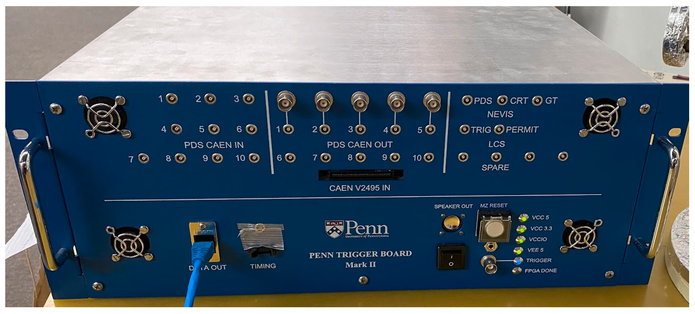
The Penn or Photon Trigger Board (PTB, shown in Figure 1) intersects all the SBND hardware trigger components. Previously used in DUNE 35-ton prototype [11], PTB is a motherboard that establishes hardware interface with the trigger subsystems, while a field-programmable gate array (FPGA) implements trigger logic and has interface with the timing system. A Linux-based CPU configures the FPGA and communicates with the DAQ software v1_08_02. Both FPGA and CPU side are part of the MicroZED [12] programmable board (Avnet, Pheonix, AZ, USA).
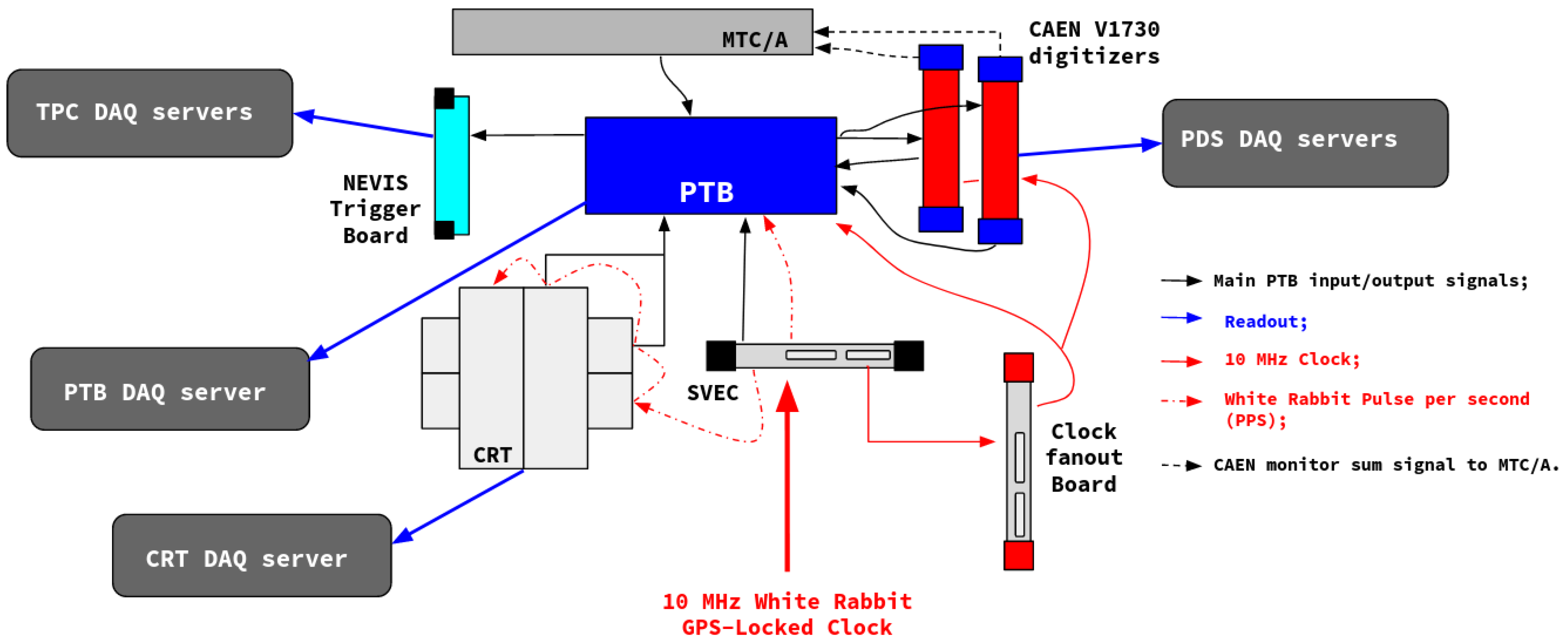
The main PTB connections to the electronic subsystems are summarized in Figure 2. We present a short description of them as follows:
- PDS—CAEN V1730 digitizers: The signals from the PMTs and some of the X-ARAPUCAS are digitized by ten commercial CAEN V1730s (CAEN S.p.A., Viareggio, Italy), 16 channel modules. For the PMT digitizers, the trigger logic is built by pairs of odd–even channels and are configured as AND, OR, ONLY A and ONLY B. It is possible to define the so-called “majority level” by declaring the number of PMT pairs above a pre-set threshold in a specific time window. If the trigger logic is satisfied, CAEN V1730 sends an output signal to the PTB. Conversely, PTB serves as an external trigger to start the digitizers’ readout. We will discuss PTB trigger logic in Section 3.
- PDS—MTC/A: CAEN V1730 modules also have an analog monitor output whose signals are proportional to the number of PMT pairs that are above a pre-set threshold. Such PMT multiplicity signals are inputs to the MTC/A. The MTC/A sums the signals from multiple V1730 digitizers and compares them to three individually programmed thresholds: LOW, MEDIUM and HIGH. An over-threshold signal from any of these discriminators propagates a trigger signal from MTC/A to the PTB. We will show in Section 4 how to program the MTC/A thresholds using PTB CPU side.
- Cosmic Ray Tagger (CRT): The Cosmic Ray Tagger, or CRT, system will entirely surround the SBND cryostat. It is responsible to measure crossing muons from cosmic sources. Each CRT basic module is formed by scintillation strips placed side by side and covered with an aluminum case. When a cosmic muon interacts with this module, scintillation light is produced and propagates along the CRT module. The signal is collected by Silicon PMTs and processed by electronics placed on the edge of each module. For further details, see Ref. [13]. The CRT panels are displayed in a vertical–horizontal overlaid configuration around SBND cryostat. In this way, the trigger logic for the CRT modules is defined by the coincidence of cosmic muon hits between two overlaid layers. When this logic is satisfied, the PTB receives a trigger pulse.
- NEVIS Trigger Board: The LArTPC-dedicated trigger system mentioned in Section 2 is denominated NEVIS trigger board. The PTB communicates with the NEVIS trigger board by sending pulses from PDS- and CRT-related triggers.
- Timing and Accelerator Complex signals: White Rabbit (WR) timing system [14] provides 10 MHz GPS-Locked Clock and pulse per second (PPS) to SBND trigger system. These signals are distributed using a WR fine delay and digital input output inside SVEC card as well as a clock-fanout module. The NEVIS trigger board as well as CRT electronics have independent internal clocks. The information from the accelerator complex is also delivered to the subsystems through WR. There are two main types of beam signals: the Booster Extraction Signal, sent when protons are leaving the accelerator ring, and the Resistive Wall Monitor, which signalizes the proton current upstream to the beam target.
- DAQ: The Data Acquisition system is responsible for the subsystem readout. DAQ establishes connection to the electronics through the servers. It is in charge to properly set user-defined configurations to the boards for the run, acquires and assembles data fragments and directs them to online monitoring or offline storage.
Low- and High-Level Triggers
The PTB uses the inputs from the various trigger subsystems to perform its trigger logic. There are two types of PTB triggers: Low-Level Triggers (LLT), where the logic (coincidence, channel mask, etc.) is made with inputs from the same subsystem, and High-Level Triggers (HLT), where a compound of Low-Level Triggers participate in the trigger decision. When the conditions are satisfied, PTB sends the formed LLT and HLT to the DAQ and, in the case of the HLTs, generates trigger pulses to the other subsystems.
It is important to emphasize the flexibility of the SBND Trigger System, once the PTB LLTs and HLTs can be configured in a wide range of possibilities and their configuration is relatively fast, in the case of testing multiple scenarios during the physics run.
4. The Analog Master Trigger Card Configuration
As described in Section 3, MTC/A monitors the overall PMT activities by discriminating its inputs into “low”, “medium” and “high” signals. The configuration of these discriminators occurs using the PTB Linux side. Each threshold value is set by programming a single digital-to-analog converter (DAC). We need to assign a 12 bit value to the DAC that corresponds to a specific voltage in the range [−5 V, 5 V].
Basically, we follow the steps below, considering the configuration of only one threshold:
- Use the PTB Linux side to map the MTC/A register addresses into virtual memory addresses. Use these memory pointers to change bit values;
- For each MTC/A, we have five bits to assign: one for each threshold value, one for clock and one for syncbar;
- Write “0” for the syncbar bit to enable bit assignment;
- Set 32 clock cycles by writing to the memory address a sequence of “0” and “1” on the bit designated for clock;
- After four clock-edge falls (from “1” to “0”), start writing the 12 bit number correspondent to the desired threshold voltage on the bit assigned for the threshold value;
- After 12 clock-edge falls, set syncbar to “1” to lock more bit assignment.
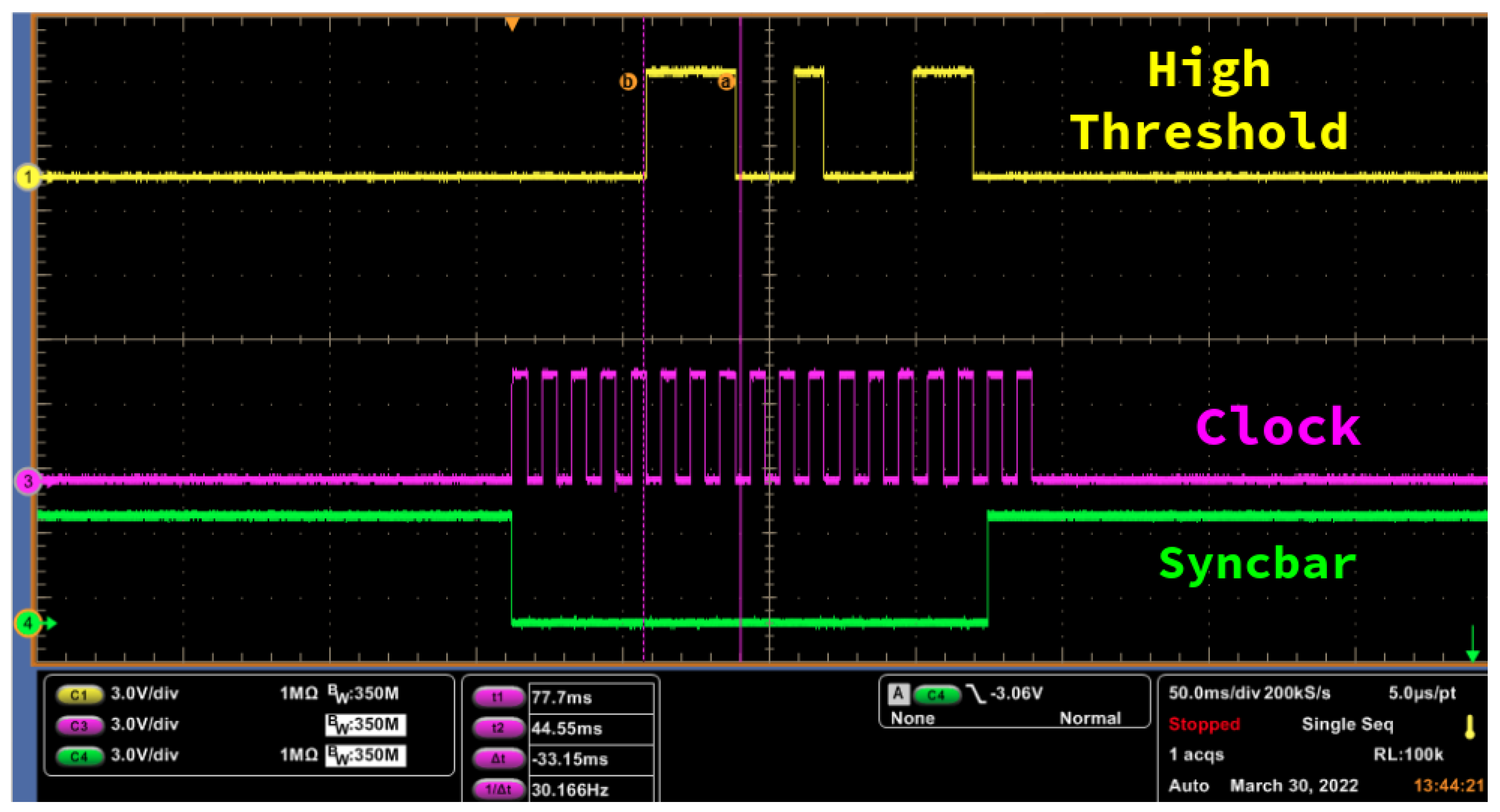
The above steps are summarized in Figure 3, where 3.9 V was programmed in the “high” threshold.
5. Summary
The statistical power of SBND enables it, as a single detector or as part of an SBN program, to perform sensitive searches on sterile neutrinos and other beyond standard model scenarios as well as to precisely measure neutrino-argon cross-sections. Attempting to record over two million neutrino events per year, SBND needs an efficient trigger system to select and qualify worthy events for analysis.
We have shown in this report the capability of the SBND trigger system and specially the flexibility of the photon trigger board in communicating with all electronic subsystems and performing a significant variety of trigger logic with these subsystems inputs.
Additionally, we showed that PTB could also be used to configure MTC/A DAC with its CPU side by accessing and writing the bit values on the virtual memory.
Funding
G.V.S. thanks the financial support by US Department of Energy, Office of Science, Office of High Energy Physics Award No. DE-SC0011686.
Acknowledgments
G.V.S. is grateful for the useful discussion with SBND collaborators.
Conflicts of Interest
The author declares no conflict of interest.
References
- Rubbia, C. The Liquid Argon Time Projection Chamber: A New Concept for Neutrino Detectors; CERN-EP-INT-77-08; CERN: Geneva, Switzerland, 1977. [Google Scholar]
- Stancu, I.; Koutsoliotas, S.; Church, E.; VanDalen, G.J.; Johnson, R.A.; Raaf, J.L.; Suwonjandee, N.; Bugel, L.; Conrad, J.M.; Fleming, B.; et al. Technical Design Report for the 8 GeV Beam; Fermilab: Batavia, IL, USA, 2001. [Google Scholar] [CrossRef]
- Acciarri, R.; Adams, C.; An, R.; Aparicio, A.; Aponte, S.; Asaadi, J.; Auger, M.; Ayoub, N.; Bagby, L.; Baller, B.; et al. Design and Construction of the MicroBooNE Detector. J. Instrum. 2017, 12, P02017. [Google Scholar] [CrossRef]
- Amerio, S.; Amoruso, S.; Antonello, M.; Aprili, P.; Armenante, M.; Arneodo, F.; Badertscher, A.; Baiboussinov, B.; Ceolin, M.B.; Battistoni, G.; et al. Design, construction and tests of the ICARUS T600 detector. Nucl. Instruments Methods Phys. Res. Sect. A Accel. Spectrometers Detect. Assoc. Equip. 2004, 527, 329–410. [Google Scholar] [CrossRef]
- Acciarri, R.; Adams, C.; An, R.; Andreopoulos, C.; Ankowski, A.M.; Antonello, M.; Asaadi, J.; Badgett, W.; Bagby, L.; Baibussinov, B.; et al. A Proposal for a Three Detector Short-Baseline Neutrino Oscillation Program in the Fermilab Booster Neutrino Beam. arXiv 2015, arXiv:1503.01520. [Google Scholar]
- Machado, P.A.; Palamara, O.; Schmitz, D.W. The Short-Baseline Neutrino Program at Fermilab. Ann. Rev. Nucl. Part. Sci. 2019, 69, 363–387. [Google Scholar] [CrossRef]
- Acciarri, R.; Adams, C.; Andreopoulos, C.; Asaadi, J.; Babicz, M.; Backhouse, C.; Badgett, W.; Bagby, L.F.; Barker, D.; Barnes, C.; et al. Construction of precision wire readout planes for the Short-Baseline Near Detector (SBND). J. Instrum. 2020, 15, P06033. [Google Scholar] [CrossRef]
- Karagiorgi, G.; on behalf of SBND Collaboration. Liquid Argon TPC Trigger Development with SBND. arXiv 2019, arXiv:1910.08218. [Google Scholar]
- Cancelo, G.; Cavanna, F.; Escobar, C.O.; Kemp, E.; Machado, A.A.; Para, A.; Segreto, E.; Totani, D.; Warner, D. Increasing the efficiency of photon collection in LArTPCs: The ARAPUCA light trap. J. Instrum. 2018, 13, C03040. [Google Scholar] [CrossRef]
- Machado, A.A.; Segreto, E.; Warner, D.; Fauth, A.; Gelli, B.; Maximo, R.; Pizolatti, A.; Paulucci, L.; Marinho, F. The X-ARAPUCA: An improvement of the ARAPUCA device. J. Instrum. 2018, 13, C04026. [Google Scholar] [CrossRef]
- Adams, D.L.; Alion, T.; Anderson, J.T.; Bagby, L.; Baird, M.; Barr, G.; Barros, N.; Biery, K.; Blake, A.; Blaufuss, E.; et al. Photon detector system timing performance in the DUNE 35-ton prototype liquid argon time projection chamber. J. Instrum. 2018, 13, P06022. [Google Scholar] [CrossRef]
- AVNET. Development Board Based on the Zynq-7000 SoC—MicroZED. 2022. Available online: https://www.avnet.com/wps/portal/us/products/avnet-boards/avnet-board-families/microzed/ (accessed on 29 November 2022).
- Auger, M.; Tutto, M.D.; Ereditato, A.; Fleming, B.T.; Goeldi, D.; Gramellini, E.; Guenette, R.; Ketchum, W.; Kreslo, I.; Laube, A.; et al. A Novel Cosmic Ray Tagger System for Liquid Argon TPC Neutrino Detectors. Instruments 2017, 1, 2. [Google Scholar] [CrossRef]
- Jansweijer, P.P.M.; Peek, H.Z.; Wolf, E.D. White Rabbit: Sub-nanosecond timing over Ethernet. Nucl. Instruments Methods Phys. Res. Sect. A Accel. Spectrometers Detect. Assoc. Equip. 2013, 725, 187–190. [Google Scholar] [CrossRef]
Figure 1.
Front view of the Photon Trigger Board (University of Pennsylvania, Philadelphia, PA, USA), showing connectors in the chassis for some electronic subsystems: PDS, timing and LArTPC (NEVIS) trigger board.
Figure 1.
Front view of the Photon Trigger Board (University of Pennsylvania, Philadelphia, PA, USA), showing connectors in the chassis for some electronic subsystems: PDS, timing and LArTPC (NEVIS) trigger board.

Figure 2.
Summary of SBND Trigger System showing the main connections the Photon Trigger Board has with other trigger subsystems, timing and DAQ. The arrows show the direction of data stream and colors state the purpose of the connection, defined in the bottom right label.
Figure 2.
Summary of SBND Trigger System showing the main connections the Photon Trigger Board has with other trigger subsystems, timing and DAQ. The arrows show the direction of data stream and colors state the purpose of the connection, defined in the bottom right label.

Figure 3.
Oscilloscope channels streaming the signals for programming 3.9 V in one single MTC/A threshold: channel 1 (yellow curve) represents the “high” threshold value, channel 3 (magenta curve) is the clock action and channel 4 (green curve) is the reset bar. The oscilloscope cursors “b” and “a” highlight the bit values changing at the clock-edge fall.

Disclaimer/Publisher’s Note: The statements, opinions and data contained in all publications are solely those of the individual author(s) and contributor(s) and not of MDPI and/or the editor(s). MDPI and/or the editor(s) disclaim responsibility for any injury to people or property resulting from any ideas, methods, instructions or products referred to in the content. |
© 2023 by the author. Licensee MDPI, Basel, Switzerland. This article is an open access article distributed under the terms and conditions of the Creative Commons Attribution (CC BY) license (https://creativecommons.org/licenses/by/4.0/).
Share and Cite
MDPI and ACS Style
Stenico, G.V., on behalf of SBND Collaboration. SBND Trigger System: Status and MTC/A Configuration. Phys. Sci. Forum 2023, 8, 60. https://doi.org/10.3390/psf2023008060
AMA Style
Stenico GV on behalf of SBND Collaboration. SBND Trigger System: Status and MTC/A Configuration. Physical Sciences Forum. 2023; 8(1):60. https://doi.org/10.3390/psf2023008060
Chicago/Turabian StyleStenico, G. V. on behalf of SBND Collaboration. 2023. "SBND Trigger System: Status and MTC/A Configuration" Physical Sciences Forum 8, no. 1: 60. https://doi.org/10.3390/psf2023008060