1. Introduction
The main goal of the Mu2e experiment at Fermilab is to search for indications of charged lepton flavor violation [
1]. To achieve this goal, the experiment will search for the conversion of a negative muon into an electron in the field of a nucleus, by searching for the monoenergetic 105-MeV electrons emitted in conversions of muons stopped in an Al target. One of the central elements of the experiment is its production target system, where negative pions and muons are generated in interactions of the 8 GeV primary proton beam within a tungsten target, shaped similarly to a rod. These particles are transported through the Mu2e solenoids to the Al target in the detector solenoid, resulting in around 3.6 × 10
20 stopped negative muons in three years of running, using an 8 kW, 8 GeV proton beam [
2].
The Mu2e experiment will be extended to a next-generation experiment, Mu2e-II, with a single event sensitivity improved by a factor of 10 or more [
3]. The greater sensitivity is enabled by using a higher intensity proton beam from the new PIP-II accelerator. The PIP-II accelerator is an 800 MeV SRF linac capable of CW operation at 2 mA (1600 kW); the Mu2e-II experiment would use 100 kW of that capacity, and would increase stopped muon production by an order of magnitude. The higher beam intensity will require a substantially more advanced target design. The passively-cooled fixed target used for Mu2e cannot handle the increased power.
2. Target Design Choices
The target system must fit within the bore of the Mu2e production solenoid, including its heat and radiation shield (HRS). Beam heating and radiation damage in the target components must be kept below safe operational limits.
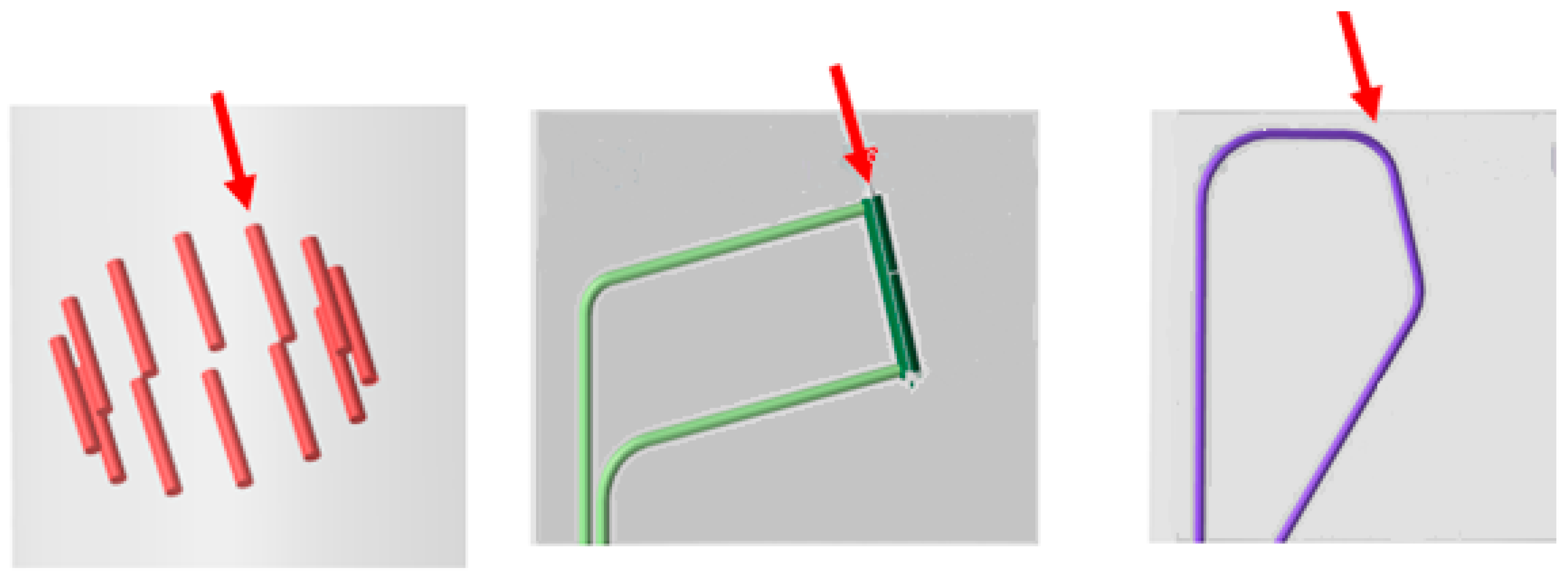
We considered three different options for the Mu2e-II target system design. The first target option consists of a circular array of target material cylinders (
Figure 1, left). Rotation of the array over operational periods places different cylinders in the beam interaction region, distributing beam heating and radiation damage over the target array. Radiative cooling may then be sufficient, although it could be complemented with a He flow system. In the second target option, the target consists of a granular material held fixed in the beam interaction region. The granular material could be a lattice of solid target balls, with He gas flow through the lattice as the cooling method (
Figure 1, center). The third one is a “conveyor”-type target, in which spheres of a target material confined within a tube will circulate through the beam interaction region, thus continuously delivering new elements of target material into the beam, and then removing the exposed target material from the beam for cooling (
Figure 1, right). Passive cooling of the target materials can be supplemented by He gas flow.
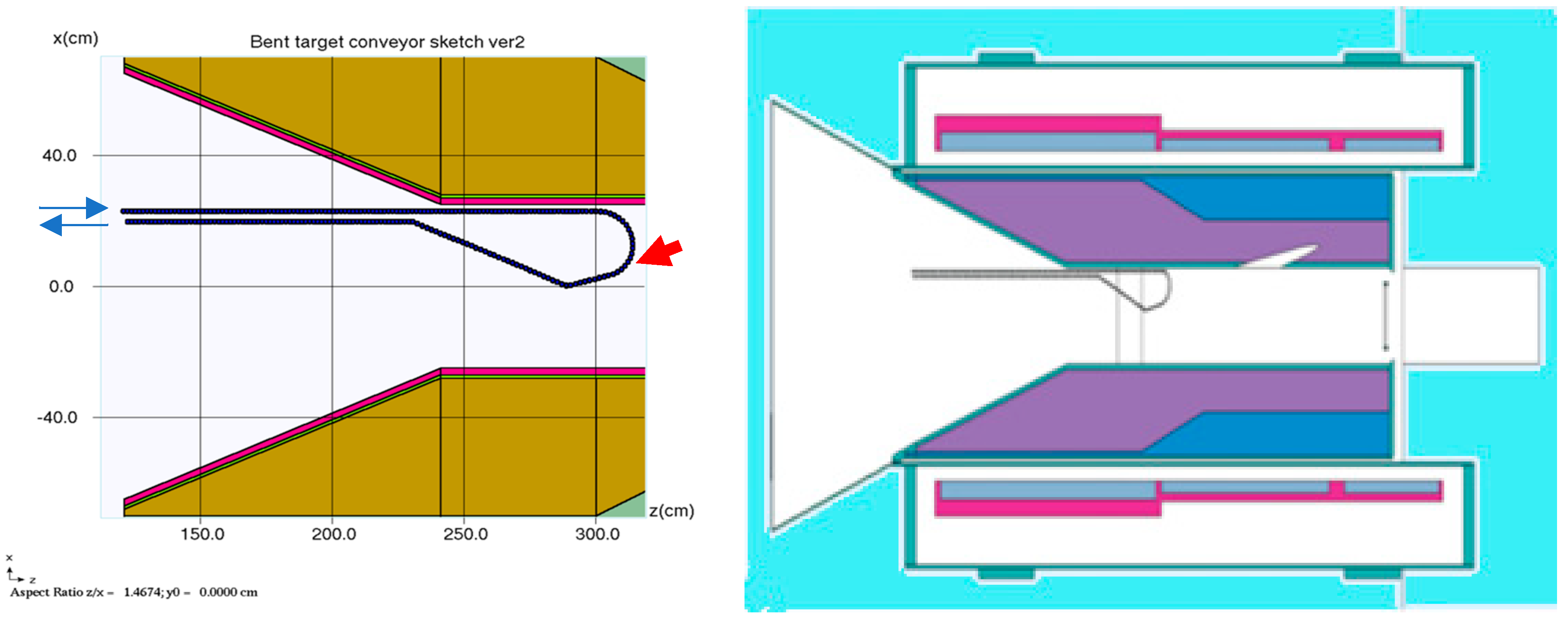
The design must be as compatible as possible with the Mu2e Heat and Radiation Shield (HRS) within the Mu2e production solenoid; the Mu2e HRS has an inner bore of 20 cm radius (see
Figure 2). The rotating element design would require a large space with supporting hardware and rotation mechanisms, which would not fit within that limited bore. The supporting hardware and multiple targets would also interfere with muon transport from the production target to the detector solenoid. Therefore, in this initial stage of consideration, we ruled out the rotating element design. The rotating element target would, nevertheless, have an advantage in that the rotating placement of several target rods in the beam would effectively distribute the heat load as well as radiation damage. We have postponed further consideration of this target option until it can be ensured that HRS space requirements can be satisfied.
The fixed granular target option (
Figure 1, center) requires a smaller space within the HRS bore; however, its cooling is inefficient because all of the beam energy is deposited at the same locations on the target, since the target would not be removed or replaced during beam operations. Thermal cooling would require continuous He flow. MARS15 [
4] simulations have shown that its peak radiation damage will be higher than 300 DPA/yr. Avoiding DPA limits would require very frequent replacement of the target (almost every month of operation). Therefore, the fixed granular target option was also ruled out.
The conveyor target (
Figure 1, right), in which spherical target elements are moved through a confining tube into the HRS bore through the beam interaction region and then removed out of the HRS bore, appears to be the most optimal among the considered options. Its downside seems to be its relative technical complexity, and that requires development of prototypes for mechanical and thermal tests. However, in other parameters, it outperforms the other options. First, the conveyor target would occupy a relatively small space in the HRS bore. Only the beam interaction section, and the inlet and outlet channels, have to be located in the HRS. Other components such as the circulation driver and the cooling gas equipment can be placed outside the HRS. Secondly, helium gas flow can be used for both cooling and moving the target elements inside the conveyor (in addition to a mechanical driver). Thirdly, radiation damage accumulated in the target can be distributed among a large number of circulating elements and minimized.
Due to these considerations, we selected the conveyor target as the baseline version of the Mu2e-II production target.
3. Energy Deposition in the Conveyor Target
MARS15 [
4] and FLUKA [
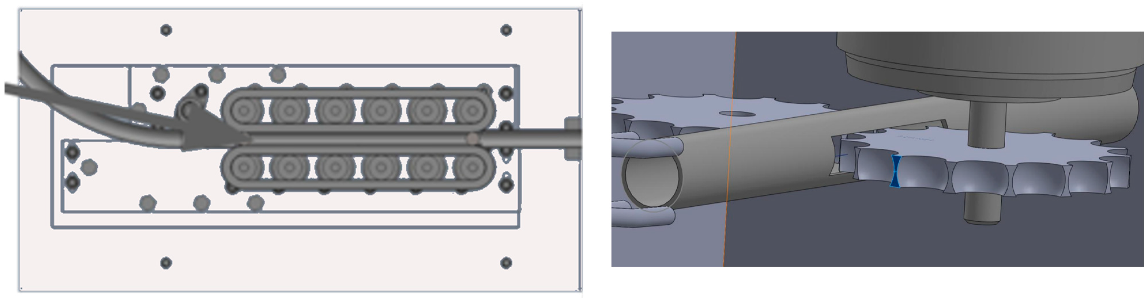
5] simulations of radiation deposition and muon production were performed using the geometries shown in
Figure 2. The optimal interaction zone length (the straight section in the target) was found from optimization studies to be ~9 spherical elements (for W or WC with 0.5 cm radius). For other prospective target materials, the optimal interaction length should be longer, if the densities of the materials are less than W. For example, for a SiC target, the length should be ~19 spherical elements. This model assumes the radii of the spherical elements to be 0.5 cm. Simulations were also made for 0.63 cm and 0.75 cm radius spheres.
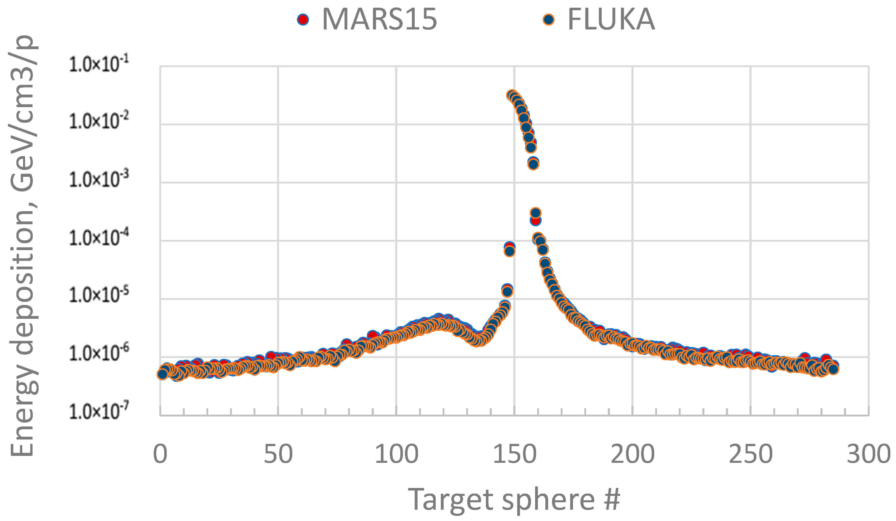
Figure 3 displays the results of simulation studies of energy deposition in a W target with ~300 circulating spheres (3 m conveyor loop length). The total simulated power deposition in the target was found to be 31.8 kW, assuming a 100 kW incident beam. The peak displacements per atom (DPA) using the Nordlund model [
6] was calculated to be ~330 DPA/yr. (assuming non-moving spheres in the beam and ignoring the tubing).
Figure 3 shows that the agreement between MARS15 and FLUKA is better than ~20% in worst cases, and overall is about 5%.
With conveyor operation, the heating and DPA would be distributed evenly among the circulating spheres, so the peak DPA/year would be less than ~10–20. The nominal velocity of the spherical elements in conveyor is expected to be ~10 cm/s (i.e., it should take an element about 1 s to pass through the beam). Sphere heating within that time should be acceptably small.
4. ANSYS Analysis of the Conveyor Target
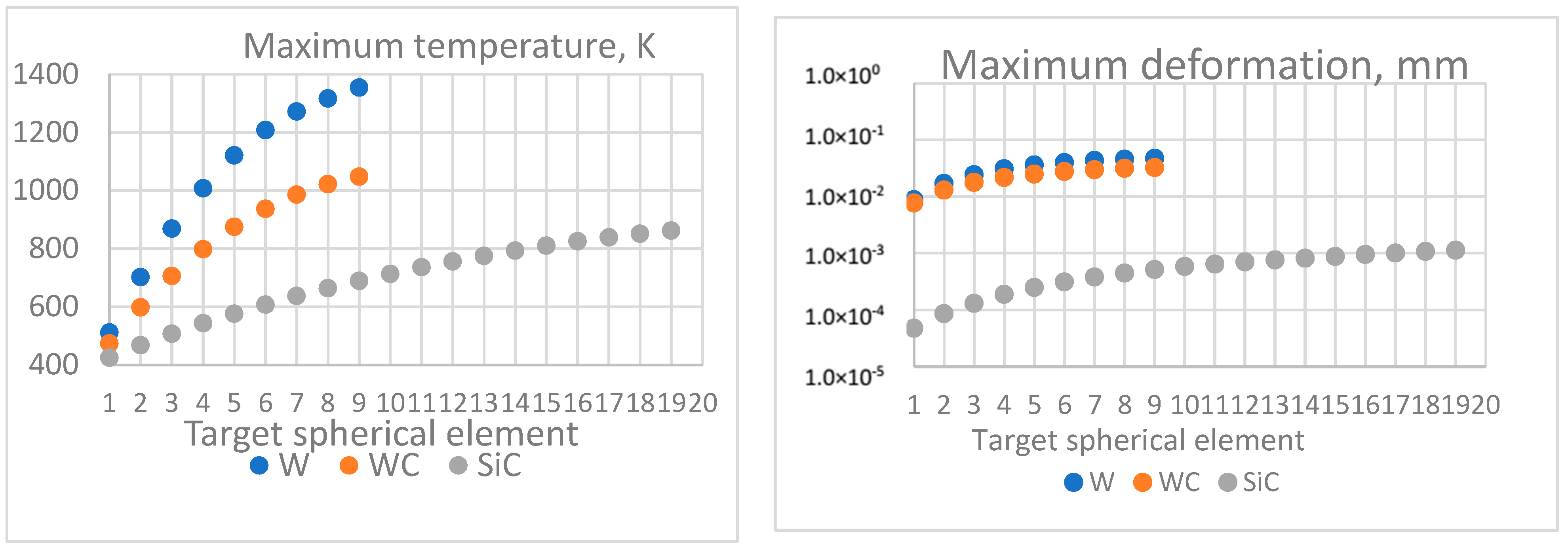
The ANSYS program was used to estimate thermal response of the target. Results of the ANSYS analysis are shown in
Figure 4. The maximum temperature for the W target after one cycle of irradiation (~1 s) is below 1400 K (the melting point for W is 3422 C). WC and SiC targets had less heating. Assuming efficient cooling in the circulating system, the target should avoid excessive heating. While radiative and conductive cooling may be sufficient, a gas cooling scheme is under consideration, and two possible candidates are two-phase ammonia cooling and He gas cooling. Additional prototype development and tests will be necessary to make a choice of the optimal cooling scheme. Maximum deformation (
Figure 4, right) for a W target is predicted to be at the level of ~0.07 mm, which is less than the expected tolerance for the piping radius.
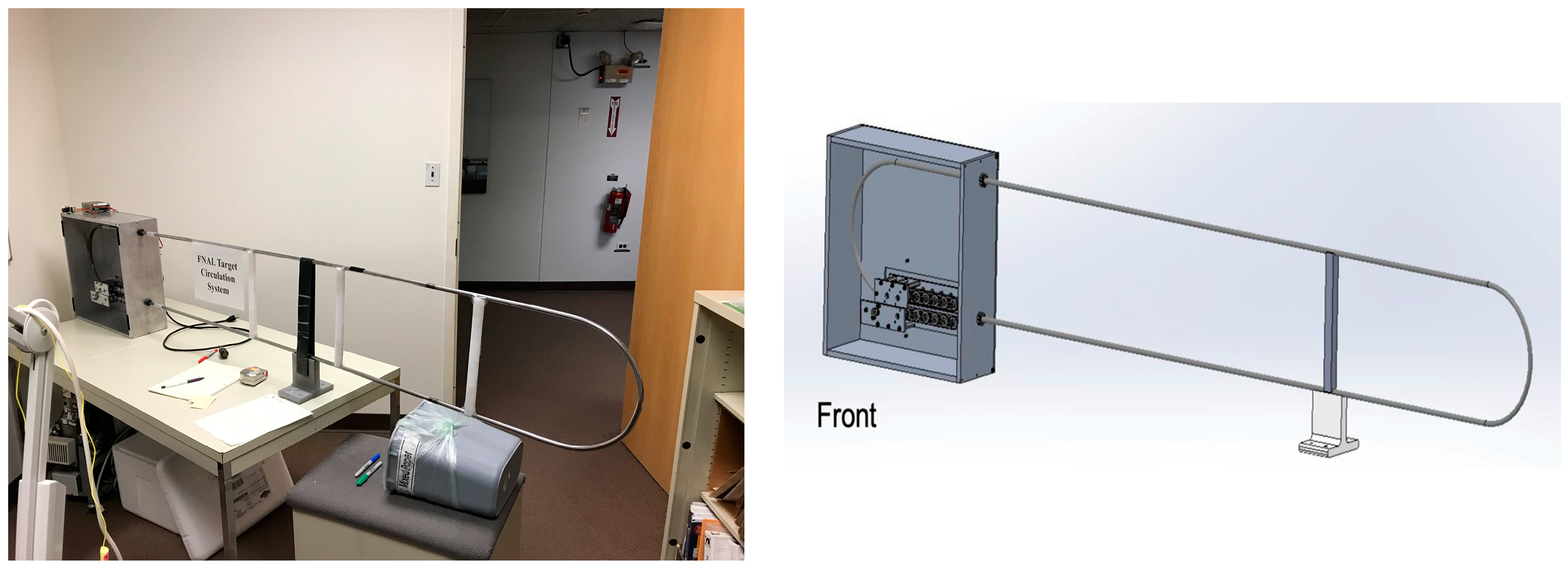
5. The Conveyor Target Prototype
Following parameters developed in the simulation studies, a prototype of the target was designed and constructed by Euclid Techlabs, LLC (see
Figure 5). The prototype used circulating stainless steel spheres (R = 0.5 cm). The prototype had a confining stainless steel tube in a racetrack shape with a U-turn radius of 15 cm and a total circumference of 245 cm. The geometry was simplified from the eventual target shape, and did not include a beam-target interaction section. The tube has a slightly larger inner radius than that of the spheres, to allow unobstructed motion. The device also was fabricated to have a sealable design, to enable an upgrade to vacuum to avoid oxidation of the target elements in air.
The circulation is driven by an electric engine, which was calibrated at Fermilab to determine the velocities of the spheres in the tube. We tested the prototype mechanically at the following velocities: 8 cm/s, 12 cm/s, and 16 cm/s. During several-hour tests at each velocity, the prototype exhibited stable operation at all three speeds. In the prototype, the track is actuated from two sides in the gearbox, and it is gripped in the drivetrain. However, after several hours of operation, the traveling belt began to crumble and needed replacement. This indicated that, during extended operation of the conveyor target, especially in the high-radiation condition, a traveling belt may not be an acceptable design element. A sprocket-based drive will be considered. Another disadvantage of the traveling belt is that, during the tests, we found that not all rollers in the gearbox were engaged; some of them slipped and did not turn. However, in general, the conveyor design, even in its initial simplified form, was found to be mechanically feasible.
6. Summary and Future Directions
We have performed simulation studies of three designs of the pion-production target for the Mu2e-II upgrade, namely rotated rod, fixed granular, and conveyor target. We found that the former two designs at this stage of considerations can be ruled out (the rotated rod one because of the larger size required in the HRS inner bore; the fixed granular one because of a large peak DPA, which would require its frequent replacement). Based on the simulations, we decided to proceed with the conveyor design. The simulations showed that the total heat load and the DPA in the conveyor design will be acceptable if we include the cooling of the spherical elements between cycles of irradiation and replacement when they acquire a significant amount of radiation defects. DPA limitations of the confining tube will be considered. We designed and mechanically tested the first prototype. Our tests supported the potential feasibility of the conveyor design.
Our initial prototype should be followed by a second prototype which more closely matches the eventual Mu2e-II target. The geometry of the circulating tube should more closely match the operational geometry, including a straight section for beam–target interaction. The belt drive should be replaced by a sprocket system (See
Figure 6). Circulation of W or WC spheres should be included. If possible, a gas cooling system should be included. The properties of the confining tube should be reconsidered, including heating and DPA calculations, obtaining a determination of the optimum tube material.
Author Contributions
Conceptualization, D.P. and V.P.; design development, K.L., J.P., S.M. and V.P.; ANSYS analysis, I.F.; protype design and testing, A.L.; simulations, V.P., D.N. and S.M.; writing—original draft preparation, V.P. and D.N.; writing—review and editing, K.L.; supervision and project administration, V.P. and D.P.; All authors have read and agreed to the published version of the manuscript.
Funding
This work is supported by the Fermi National Accelerator Laboratory, managed and operated by Fermi Research Alliance, LLC under Contract No. DE-AC02-07CH11359 with the U.S. Department of Energy. The work of S.M. was supported by the EU Horizon 2020 Research and Innovation Programme under the Marie-Sklodowska-Curie Grant Agreement No.101006726 (aMUSE).
Institutional Review Board Statement
Not applicable.
Informed Consent Statement
Not applicable.
Data Availability Statement
Acknowledgments
This work is supported by the Fermi National Accelerator Laboratory, managed and operated by Fermi Research Alliance, LLC under Contract No. DE-AC02-07CH11359 with the U.S. Department of Energy. The U.S. Government retains and the publisher, by accepting the article for publication, acknowledges that the U.S. Government retains a non-exclusive, paid-up, irrevocable, world-wide license to publish or reproduce the published form of this manuscript, or allow others to do so, for U.S. Government purposes.
Conflicts of Interest
The authors declare no conflict of interest.
References
- Bartoszek, L.; Barnes, L.; Miller, J.P.; Mott, A.; Palladino, A.; Quirk, J.; Roberts, B.L.; Crnkovic, J.; Polychronakos, V.; Tishchenko, V.; et al. Mu2e Technical Design Report. FERMILAB-TM-2594, FERMILAB-DESIGN-2014-01. arXiv 2014, arXiv:1501.05241. [Google Scholar]
- Bernstein, R. The Mu2e Experiment. Front. Phys. 2019, 7, 1. [Google Scholar] [CrossRef]
- Byrum, K.; Corrodi, S.; Oksuzian, Y.; Winter, P.; Xia, L.; Edmonds, A.W.J.; Miller, J.P.; Mott, J.; Marciano, W.J.; Szafron, R.; et al. Mu2e-II: Muon to electron conversion with PIP-II, Contribution to Snowmass. arXiv 2021, arXiv:2203.07569. [Google Scholar]
- Mokhov, N.V.; James, C.C. The MARS Code System User’s Guide, Version 15 (2016). Fermilab-FN-1058-APC [Preprint] 2017. Available online: https://mars.fnal.gov (accessed on 8 September 2023).
- Böhlen, T.T.; Cerutti, F.; Chin, M.P.W.; Fassò, A.; Ferrari, A.; Ortega, P.G.; Mairani, A.; Sala, P.R.; Smirnov, G.; Vlachoudis, V. The FLUKA Code: Developments and challenges for high energy and medical applications. Nucl. Data Sheets 2014, 120, 211–214. [Google Scholar] [CrossRef]
- Nordlund, K.; Zinkle, S.J.; Sand, A.E.; Granberg, F.; Averback, R.S.; Stoller, R.E.; Suzudo, T.; Malerba, L.; Banhart, F.; Weber, W.J.; et al. Primary radiation damage: A review of current understanding and models. J. Nucl. Mat. 2018, 512, 450. [Google Scholar] [CrossRef]
| Disclaimer/Publisher’s Note: The statements, opinions and data contained in all publications are solely those of the individual author(s) and contributor(s) and not of MDPI and/or the editor(s). MDPI and/or the editor(s) disclaim responsibility for any injury to people or property resulting from any ideas, methods, instructions or products referred to in the content. |
© 2023 by the authors. Licensee MDPI, Basel, Switzerland. This article is an open access article distributed under the terms and conditions of the Creative Commons Attribution (CC BY) license (https://creativecommons.org/licenses/by/4.0/).


 ,
, 


