Article

Route Optimization of Unmanned Aerial Vehicle Sensors for Localization of Wireless Emitters in Outdoor Environments †

1
Tokyo Institute of Technology, Tokyo 152-8550, Japan
2
Softbank Corp., Tokyo 105-7537, Japan
*
Author to whom correspondence should be addressed.
This article is a revised and expanded version of a paper entitled Study on the Optimization of Flight Paths for Fingerprint-Based Outdoor Localization Using UAV, which was presented at the virtual IEEE PIMRC2022 conference held on 12–15 September 2022.
Network 2023, 3(3), 326-342; https://doi.org/10.3390/network3030016
Submission received: 31 July 2023 / Revised: 10 August 2023 / Accepted: 16 August 2023 / Published: 18 August 2023
(This article belongs to the Special Issue Innovative Mobile Computing, Communication, and Sensing Systems)

Abstract

:
Localization methods of unknown emitters are used for the monitoring of illegal radio waves. The localization methods using ground-based sensors suffer from a degradation of localization accuracy in environments where the distance between the emitter and the sensor is non-line-of-sight (NLoS). Therefore, research is being conducted to improve localization accuracy by utilizing Unmanned Aerial Vehicles (UAVs) as sensors to ensure a line-of-sight (LoS) condition. However, UAVs can fly freely over the sky, making it difficult to optimize flight paths based on particle swarm optimization (PSO) for efficient and accurate localization. This paper examines the optimization of UAV flight paths to achieve highly efficient and accurate outdoor localization of unknown emitters via two approaches, a circular orbit and free-path trajectory, respectively. Our numerical results reveal the improved localization estimation error performance of our proposed approach. Particularly, when evaluating at the 90th percentile of the error’s cumulative distribution function (CDF), the proposed approach can reach an error of 28.59 m with a circular orbit and 12.91 m with a free-path orbit, as compared to the conventional fixed sensor case whose localization estimation error is 55.02 m.

1. Introduction

In today’s age of diversified use of radio waves [
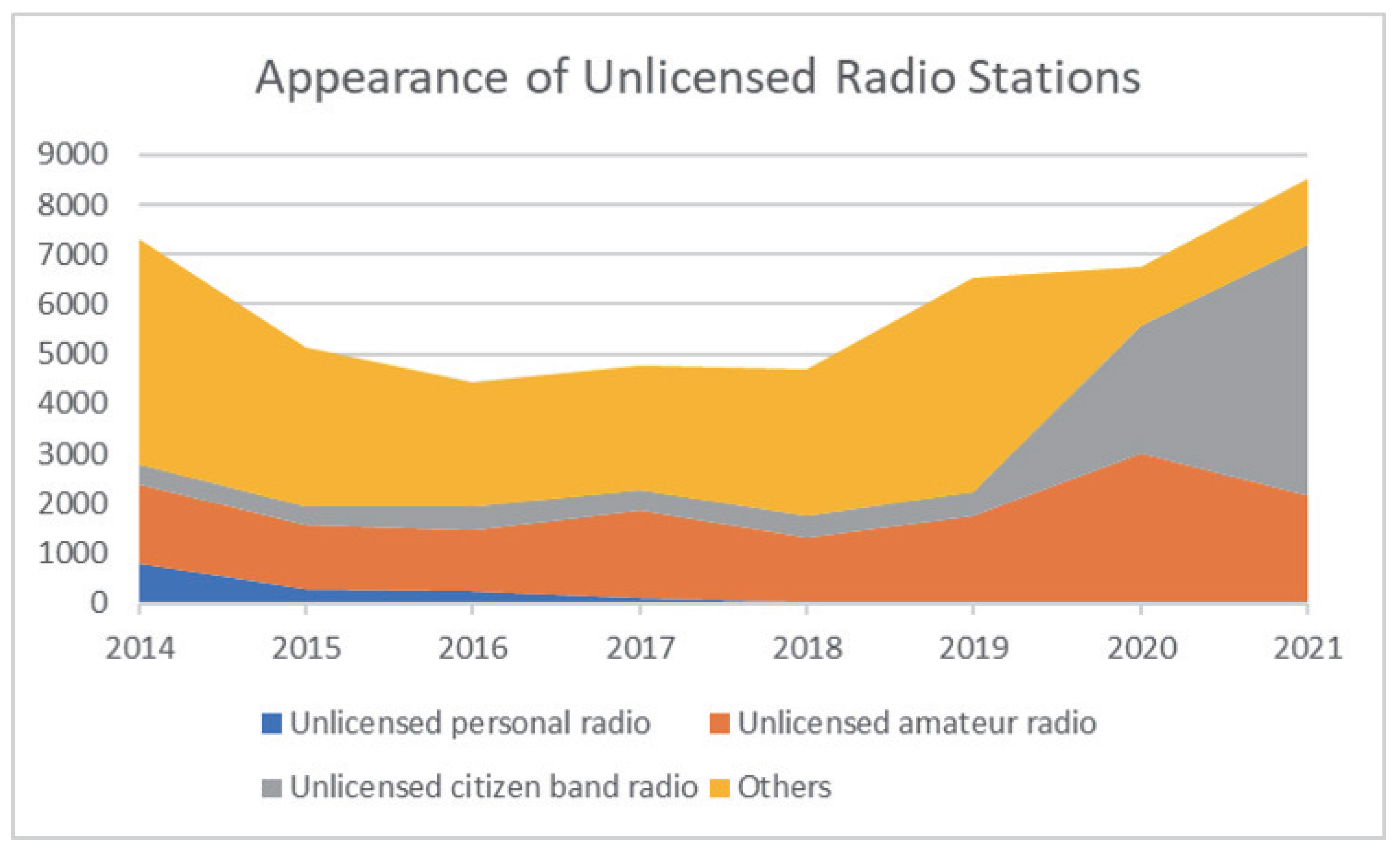
1], illegal radio waves that cause interference in wireless communication systems have become a social issue. Illegal radios (or private radios) consist of radio emitters operating without a proper license issued by authorities. The term may also refer to radios that have obtained a license but operate using frequencies outside the ranges specified by their license or transmit using powers much larger than regulations. Statistics of illegal radios in Japan from 2014 until 2021 are available on the MIC website [2], as shown in Figure 1. From the figure, the number of appearances of illegal radios has been gradually increasing in recent years. A large percentage of illegal radios consists of unlicensed citizen band radios, followed by unlicensed amateur radios.
Cases have been reported in which the use of radio waves violating the power strength and frequencies regulated by national laws caused interferences to important lifelines such as police, fire, disaster prevention, and aviation radios, as well as television and cellular systems. Also, the occurrence of fires had been reported due to malfunctions of electronic equipment. For example, in June 2015, there were reports of interference to a broadcasting service in Tokyo. The interference source was found to be a wireless transceiver imported from overseas to communicate between shops in a shopping street, and the transceiver was not licensed for use in Japan. In March 2015 in the Tochigi prefecture, an amateur radio station was set up on a dump truck without an amateur radio license. The Japanese Ministry of Internal Affairs and Communications (MIC) has developed and utilized a radio wave monitoring system called DEtect Unlicensed RAdio Stations (DEURAS) to crack down on illegal base stations, but in recent years, with the diversification of radio wave usage, there have been many different types of illegal base stations [2] that prevent the effectiveness of DEURAS.
One of the methods used to estimate the location of radio wave sources for radio wave monitoring is the geometric localization method using the angle of arrival (AOA) of the received signal. However, since the geometric localization method assumes an LoS condition between the sensor and the target, the localization accuracy deteriorates significantly in general environments of urban areas with the existence of many scattering objects, where sensors and the radio sources are normally in an NLoS condition [3,4,5,6]. In a geometric localization or triangulation approach, the location of the emitters is predicted as the intersection point of different estimated AOAs from the illegal source toward different received sensors. Due to the existence of multipath components in NLoS environments, AOA estimation errors finally result in a large localization error.
Therefore, a statistical localization method, i.e., fingerprint-based localization, has been attracting attention [4]. In particular, statistical approaches, such as machine learning, are expected to enable localization even in NLoS conditions. There are several approaches to perform pattern matching or machine learning of the fingerprints. The reader can find a good survey of pattern matching techniques in [3,7]. The most conventional approach is calculating the distance between two fingerprints. The most commonly used distance metric is the Euclidean distance, and it was used in [8] under the name Nearest Neighbour in Signal Space (NNSS). One may also use the Manhattan distance as a distance metric [9]. Other deterministic methods include the k-Nearest Neighbour (KNN), which calculates the weighted or unweighted average of k training locations, which are closest to the target’s fingerprints under a certain distance metric. One may also obtain a large number of snapshots of the training fingerprint and utilize its distribution as a location fingerprint. This is categorized as a statistical approach. If the distribution of the measured fingerprint is known, we can use the maximum likehood (ML) approach for localization. This is the approach employed in this paper (since this paper focuses on the optimization of the UAV sensor’s flight path to improve the localization estimation, the discussion of different machine learning techniques to improve localization accuracy in an NLoS environment is out of the scope of this paper. The interested reader may refer to [3,4,7] for further discussion on different machine learning techniques).
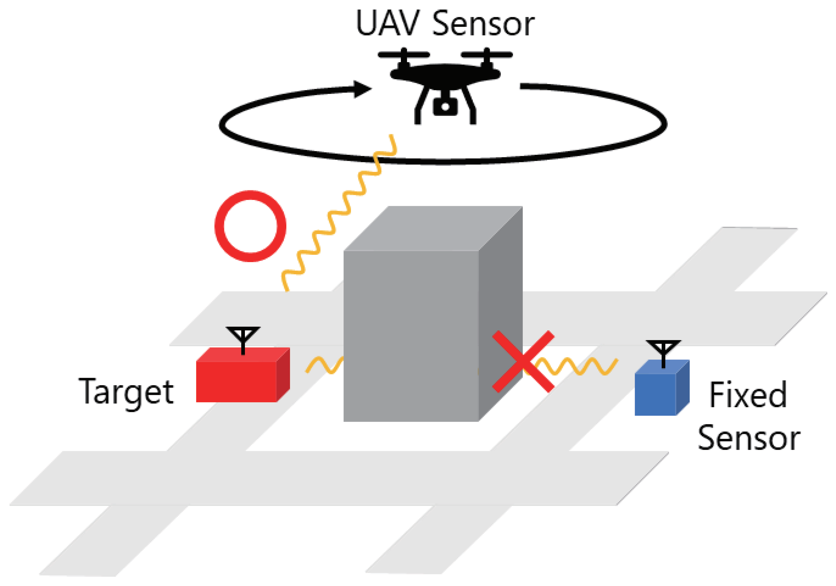
However, even with fingerprint-based localization, accuracy degradation in out-of-sight communication cannot be completely avoided, and the reliability of the system decreases in an NLoS condition when fixed sensors are deployed [
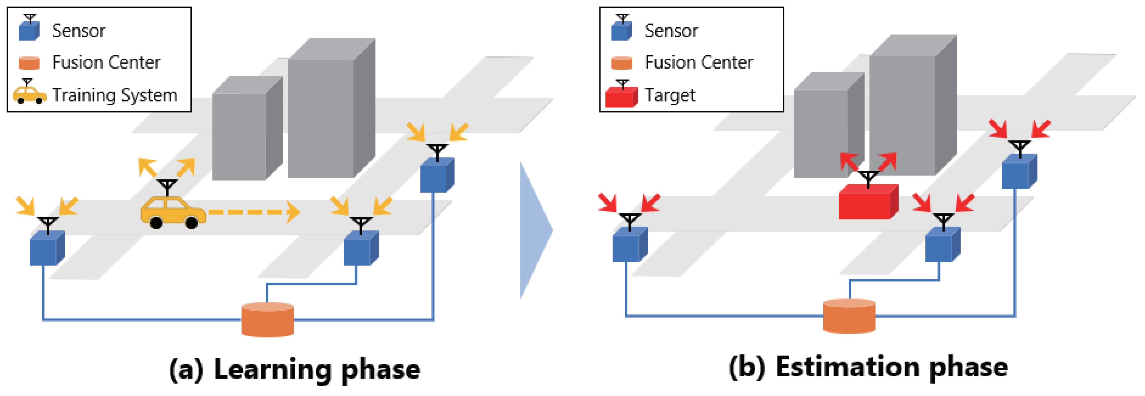
10]. In this study, a UAV is used as a sensor for fingerprint-based localization, which allows the sensor to move freely in the air and ensures LoS communication to directly receive radio waves from the target, thereby improving localization accuracy. Furthermore, employing a UAV as a sensor enables the capability of determining an optimal flight path, on which optimal UAV’s sensing points can be selected to improve localization accuracy. Compared to the conventional system of fixed ground-based sensors, our approach is more cost-efficient since only one UAV sensor is required instead of the requirement for the deployment and installation of multiple fixed ground-based sensors.
For this purpose, we propose an outdoor localization system using fingerprint-based localization and aim to realize a low-cost and high-efficiency localization system by optimizing the flight path of UAVs in this paper. The improved accuracy might depend on the selection of a suitable optimization algorithm, as explained in Appendix A of this paper. Particularly, a free-path route optimization is further considered in this paper in constrast to our previous work in [11], where only a restricted circular orbit was investigated. Numerical results will reveal the superiority of the free-path route optimization compared to the circular case, owing to the higher mobility freedom of the UAV sensor. Compared to our previous work in [11], the main contributions of this work include:
  • The investigation of a free-path trajectory that helps to further improve estimation accuracy;
  • Detailed explanations of each process of our proposed system;
  • Comparison of different optimization solving techniques;
  • Discussions about future directions/applications of the UAV-based localization system proposed in this paper.
This paper is organized as follows. Section 2 describes conventional localization methods and the proposed fingerprint-based mechanism using UAVs. The simulation setup is explained in Section 3. Numerical results and discussions are given in Section 4. Finally, Section 5 concludes this paper with our future works. Table 1 summarizes all the abbreviations used in this work.

2. Localization Methods

2.1. Localization Methods of Unknown Emitters

There are two main types of methods for estimating the location of a radio transmission source: an active method in which the target terminal receives radio waves emitted by a beacon whose absolute location is known and estimates its own location and a passive method in which a sensor receives radio waves transmitted by the target terminal and the system estimates the terminal’s location. A well-known example of the former is the Global Positioning System (GPS), but it is not suitable for estimating the location of illegal radio wave sources because of the hardware limitation of a GPS chip non-necessarily equipped in the target terminal and the need for cooperation between the localization system and the terminal to be estimated. For this reason, the monitoring of illegal radio waves often employs the latter method in which the location is estimated by the system using information on radio waves emitted by the target terminals.
The radio wave information used for location estimation includes the received signal strength indicator (RSSI), time difference of arrival (TDOA), and angle of arrival (AOA). Localization using the AOA is called triangulation, which is also used in DEURAS-D, one of the above-mentioned DEURAS [2] programs. However, such a geometric method assumes that the distance between the terminal and the sensor is in an LoS condition, but in environments with many scattering objects, e.g., urban areas, it is easy to become NLoS and the accuracy of localization is greatly degraded [7].
Therefore, this paper uses the location fingerprinting method, i.e., a statistical location estimation method, to enable location estimation even in NLoS environments. The next section provides an overview of the fingerprint-based localization.

2.2. Fingerprint-Based Localization

Fingerprint-based localization is a method that collects position-dependent information as fingerprints and statistically estimates the position by pattern matching [5]. As shown in Figure 2, fingerprint-based localization is largely divided into a learning phase and an estimation phase. In the learning phase, a location fingerprint database is constructed from the propagation characteristics of a radio wave source whose location and parameters are known in advance, which is observed by a sensor while moving. In the estimation phase, radio waves from an unknown target are observed and their positions are estimated by pattern matching with the positional fingerprint database constructed in the learning phase. This method is expected to further improve the accuracy of localization due to recent advances in statistics such as machine learning [12,13].
When actually constructing the system, it is impossible to obtain fingerprints for all observation points. Therefore, propagation characteristics are modeled, and continuous fingerprints are interpolated by regressively obtaining model parameters from propagation characteristics obtained at discrete observation points [14].
In this study, RSSI is used as the fingerprint because it is easy to implement in hardware and does not require time synchronization. When the position coordinate of the k-th emitter is u k and the RSSI observed at the n-th sensor is P n ( u k ) [ dB ] , the fingerprint vector F k DB is expressed as follows where N denotes the total number of deployed sensors.
F k DB = [ P 1 ( u k ) , , P N ( u k ) ] .
Next, let P n target [dB] be the RSSI observed by the n-th sensor from the target. The estimated position of the target u ^ is obtained by pattern matching using the maximum likelihood estimation method with the following formula [11]:
u ^ = arg max u k n = 1 N log p P n target u k .
Here, the likelihood function P n target is assumed to experience shadowing and its probability distribution function p P n target | u k follows normal distribution as follows [11].
u ^ = arg max u k n = 1 N log N P n target ; μ n , k , σ n , k ,
where the distribution’s average and standard deviation, i.e., μ n , k , σ n , k , are assumed to be obtained when calculating the ensemble average of the received signal. As described above, the target location can be estimated statistically.

2.3. Use of UAV Sensor

In the fingerprint-based localization introduced in the previous section, in general, the greater the number of sensors, the greater the amount of information in the fingerprints and the more accurate the localization. However, the use of fixed sensors increases the installation cost. Therefore, as shown in Figure 3, following the approach of [15], this study proposes the use of UAVs as sensors, which can move freely in the air, thereby substantially extending the dimensions of the location fingerprint database at a low cost. Also, even when a fixed sensor is out of sight of the target, the UAV can move to maintain an LoS condition and collect more reliable location fingerprints. As a result, improved localization accuracy can be expected, and highly efficient localization can be achieved at lower cost with a small number of sensors. In summary, this paper employs a single UAV working as a sensor node to collect RF fingerprints and estimate the location of illegal emitters at different discrete positions on the UAV’s flying trajectory. Taking advantage of the UAV’s mobility freedom, this is equivalent to the deployment of multiple fixed sensors with only a single UAV. Also, since there is only a single UAV sensor in our proposed system, there is no need for information sharing among sensors to estimate the location of a target illegal emitter. This is another advantage of our proposed UAV-based localization sensor system. It should be noted that, considering the limited power budget of a UAV, this paper restricts the RF fingerprints to only the RSSI measured at the UAV sensor since obtaining other types of RF fingerprints like the TDOA and AOA will increase the signal processing cost and circuitry size and therefore increase the power consumption at the UAV [4].
However, when using UAV sensors, it is necessary to determine their flight paths. Since flight paths that enable highly accurate localization depend on the propagation environment, a system that can optimize flight paths in any environment is required. In this paper, we propose such a system to optimize the flight path for the scenario of moving a UAV sensor and compare the localization accuracy with that of the conventional case where fixed sensors are used.

3. Simulation System

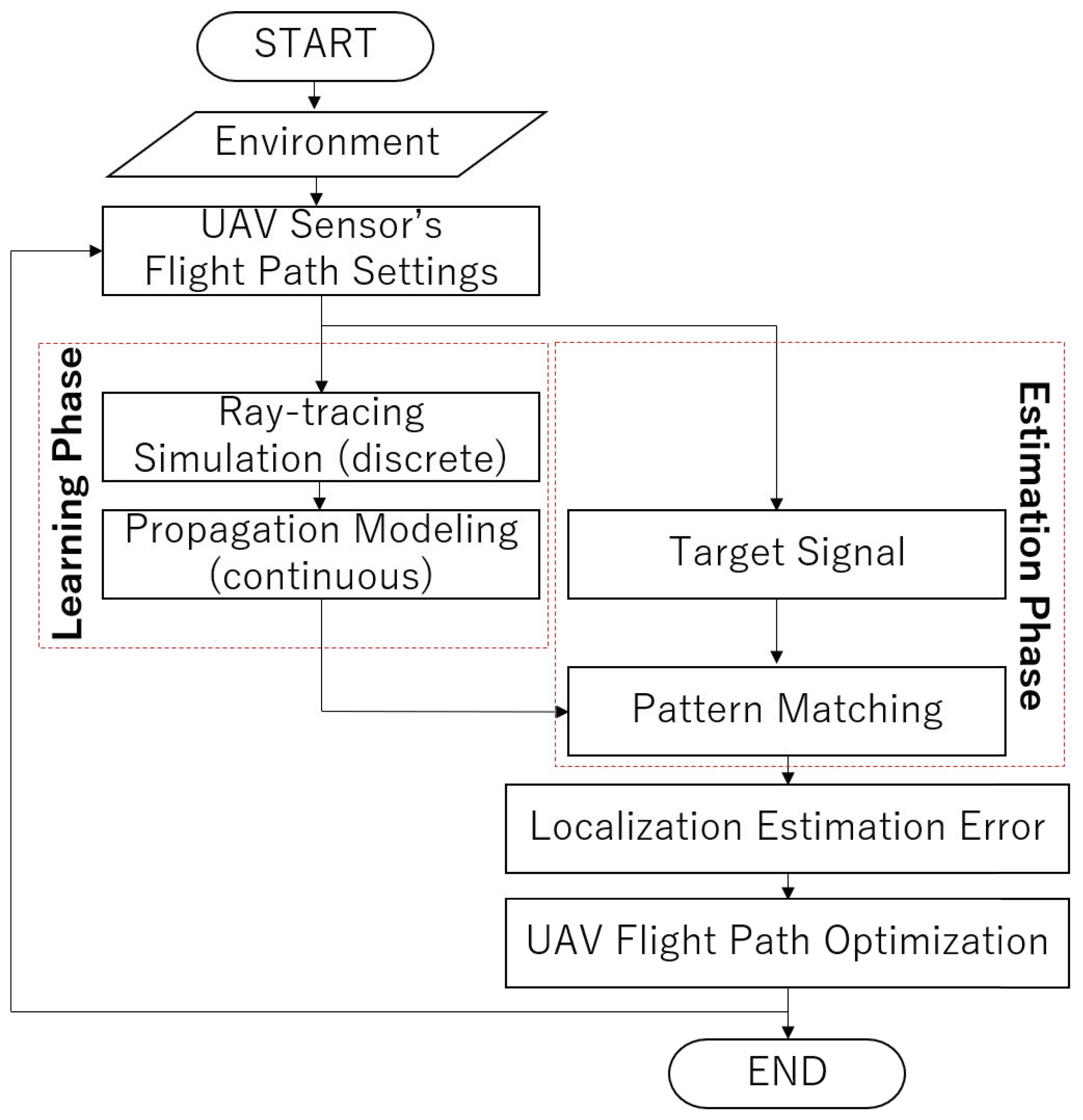
An overview of the UAV flight path optimization method proposed in this paper is shown in Figure 4. As shown in the figure, our simulation starts with the deployment of a selected outdoor environment to be evaluated by our numerical analysis. An initial trajectory of our UAV sensor is set. Based on the position of the UAV sensor and the ground-based training points, a ray-tracing simulation is conducted to emulate the propagation channels between the discrete training points and the UAV sensor. Since the target illegal transmitter’s locations might be different from those of the discrete training points, a propagation modeling approach is applied to emulate the propagation channels between arbitrary possible target locations and the UAV sensor. In the estimation phase, a machine-learning-based pattern matching algorithm is applied to compare the RF fingerprint of the target illegal emitter against the constructed RF fingerprint database. (Indeed, the pattern matching process as shown in Figure 4 can be classified as “supervised learning”, one of famous machine learning algorithms. In the first phase, a fingerprint database is constructed via the regression process explained in Section 3.2. In the second phase, the pattern matching process is conducted, i.e., the observed RF signals are compared with the constructed database to estimate the location of the illegal emitter. This paper employed the ML approach shown in Equation (3) for the estimation phase.) Based on this process, the location estimation error of a specific target location is computed. This process is repeated for all candidate locations of the target emitter to finally derive the estimation error distribution. Based on the derived distribution, our optimization algorithm is run to select another UAV flight path that helps to improve the estimation error distribution. Details on the functionality of each block will be explained as follows.

3.1. Ray-Tracing Simulation

First, as a learning phase of the fingerprinting method, the radio propagation characteristics in the simulated environment were analyzed. In this study, radio propagation simulations were conducted using the ray-tracing method. The ray-tracing method has the following characteristics [16]:
  • It traces radio waves emitted from a transmitting point as rays of light and searches for a path;
  • It geometrically calculates paths with reflection, diffraction, and transmission;
  • It can take into account multipath effects caused by obstacles;
  • It requires much less memory and computation than the FDTD method, a well-known theoretical approach.
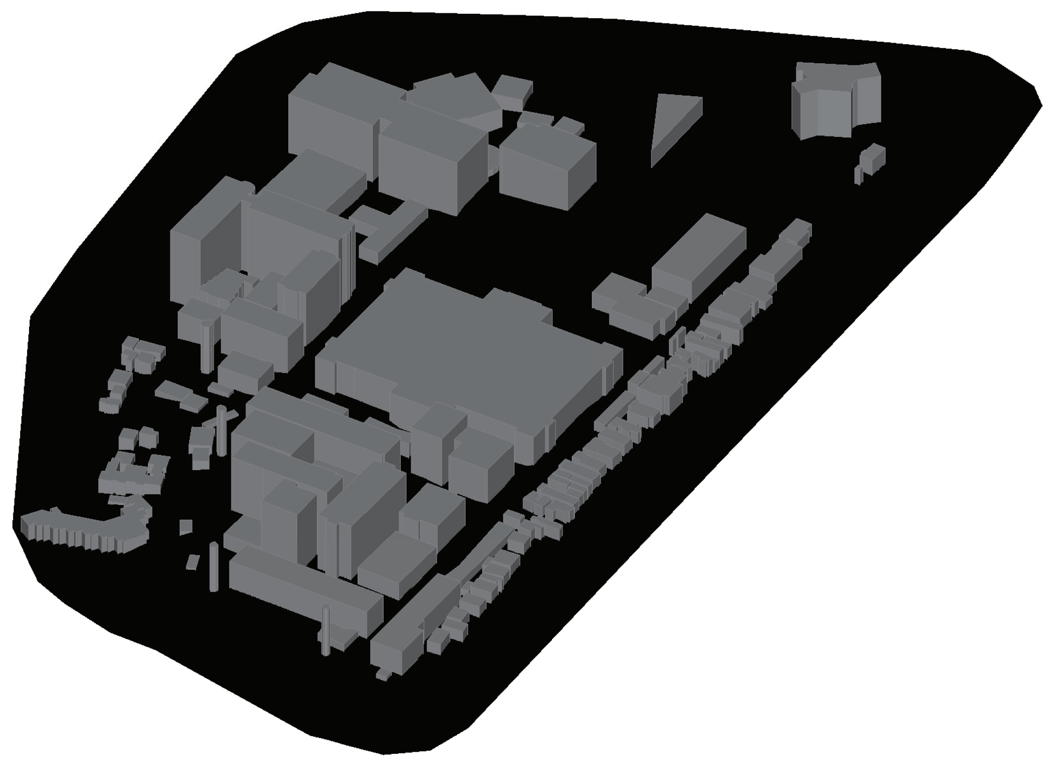
A ray-tracing simulation was performed using the radio propagation simulation software Wireless Insite. The simulation terrain model is shown in 
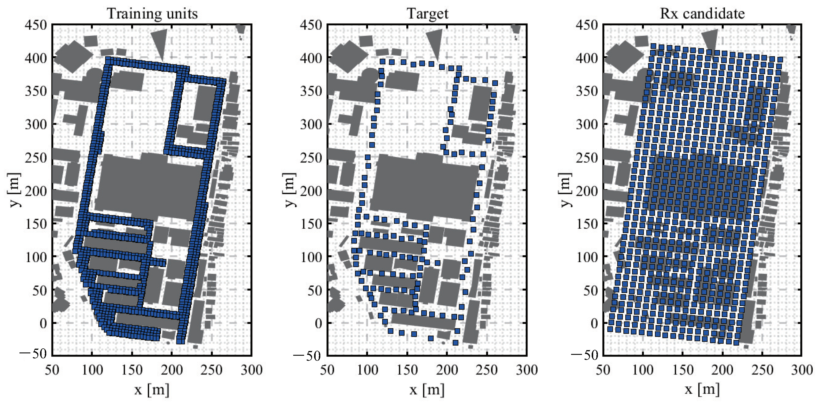
Figure 5 and the arrangement of the transmitter and sensor candidate points is shown in Figure 6.
An urban environment was assumed in this study, and a terrain that reproduced the Tokyo Institute of Technology Ookayama campus was used as the simulation terrain model.
Training units in the learning phase and targets in the estimation phase were placed at a height of 2 m, assuming that illegal radio transmission sources are on the road. Candidate points for UAV sensors were placed in a grid at heights of 50/75/100/125/150 m. The grid was designed to be as close as possible to the road surface. In this paper, it is assumed that the transmitter parameters in the learning and estimation phases are ideally matched (see [17] for bandwidth and frequency interpolation methods).
The parameters are summarized in Table 2. Note that the antennas are assumed to be omni-directional for both the transmitter and the receiver and that polarization matching is ideally achieved where vertical polarization is assumed.

3.2. Propagation Modeling

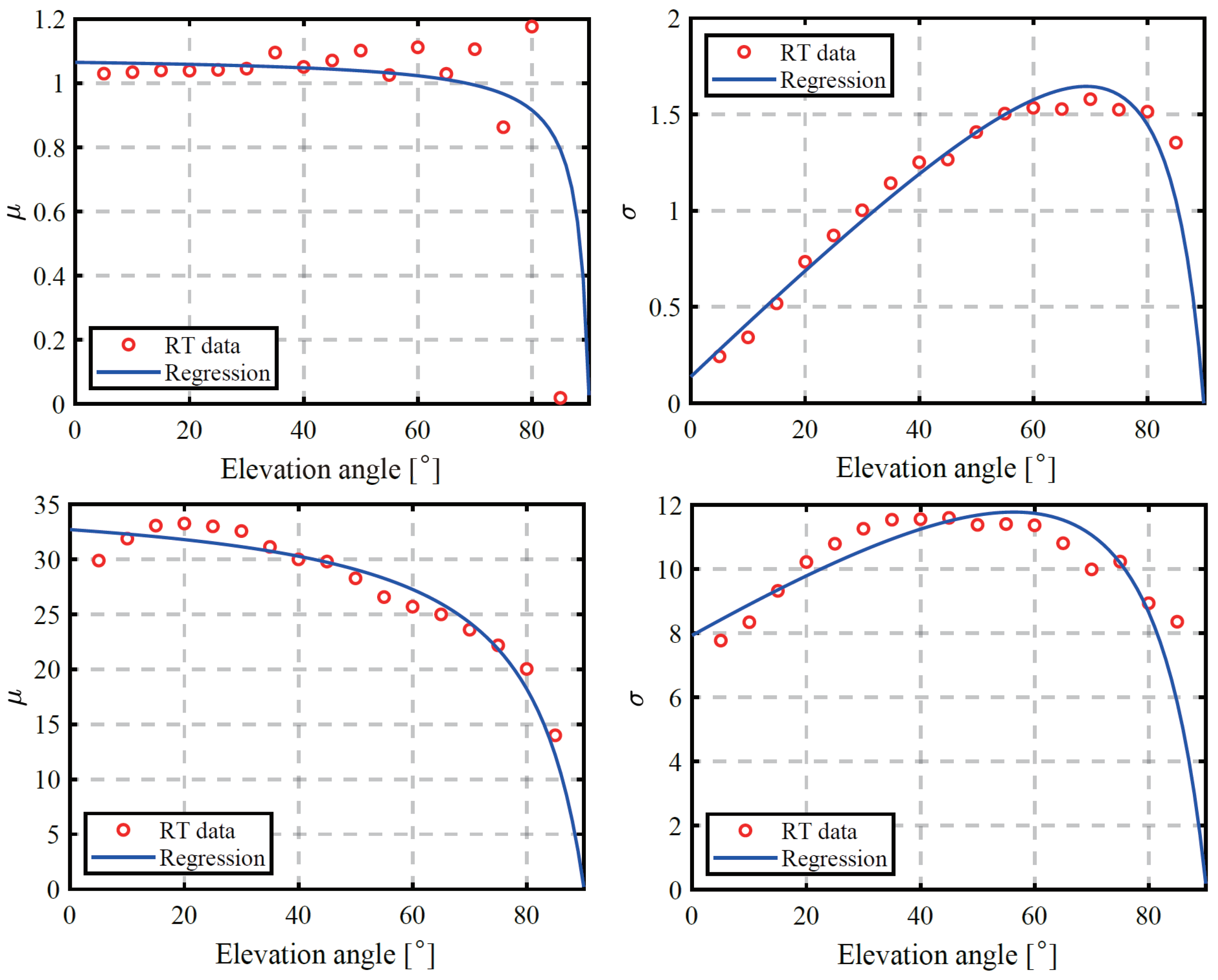
The database obtained from the ray-tracing simulation is discrete, while the actual target and UAV sensor location information is continuous. In this paper, continuous data were interpolated by applying a radio propagation model as explained below. The parameters of the model are calculated in a regressive manner from the data obtained by the ray-tracing simulation.
In this paper, we consider the following propagation loss model with the elevation angle θ e between Tx and Rx as a variable in LoS and NLoS environments [18].
PL LoS ( θ e ) = PL FSPL ( θ e ) + PL N ( θ e )
PL NLoS ( θ e ) = PL FSPL ( θ e ) + PL shadow ( θ e ) ,
where PL FSPL ( θ e ) is the free space loss [18].
PL FSPL ( θ e ) = 20 log 10 4 π f e c Δ h sin θ e .
Here, Δ h = | h rx h tx | , where h rx and h tx are the heights from the ground of the receiver and the transmitter, respectively.
PL N ( θ e ) is the loss due to noise in the LoS environment, and PL shadow ( θ e ) is the loss due to shadowing and noise in the NLoS environment. PL N ( θ e ) and PL shadow ( θ e ) are assumed to follow a normal distribution, respectively [18].
PL N ( θ e ) [ dB ] = N ( μ n , σ n )
PL shadow ( θ e ) [ dB ] = N ( μ s , σ s ) ,
where μ n , σ n and μ s , σ s are determined regressionally from the results of ray-tracing simulations. They are expressed by the following equations using experimental parameters α , β , γ , and δ [14].
θ e 2 + α θ e + β γ θ e + δ .
The results of the regression are shown in Figure 7.

3.3. LoS Probability

In order to use the aforementioned propagation model, it is necessary to perform LoS or NLoS classification on a continuous location fingerprint database. Therefore, a probabilistic LoS/NLoS classification method is used based on the LoS/NLoS information of the discrete data obtained in advance [14].
For a particle i at position u i , we are interested in eight discrete particle neighborhoods, i.e., 4 neighborhoods relative to the two-dimensional plane and 2 neighborhood planes relative to the elevation direction. At the k-th neighborhood, we define a variable c k that is 1 if the particle u k is in an LoS condition and 0 if it is in an NLoS condition, as follows [14]:
c k = 1 if LoS 0 if NLoS .
When the distance between a particle i and each neighbor point k is d i , k , the LoS probability is calculated using the weight coefficient ω i , k = d i , k 1 and variable c k with the following formula [14].
p LoS ( u i ) = k = 1 8 ω i , k c k .
Based on the LoS probability calculated by the above equation, the LoS or NLoS classification is stochastically determined and applied for our propagation model mentioned in Section 3.2.

3.4. Optimization of UAV Flight Path

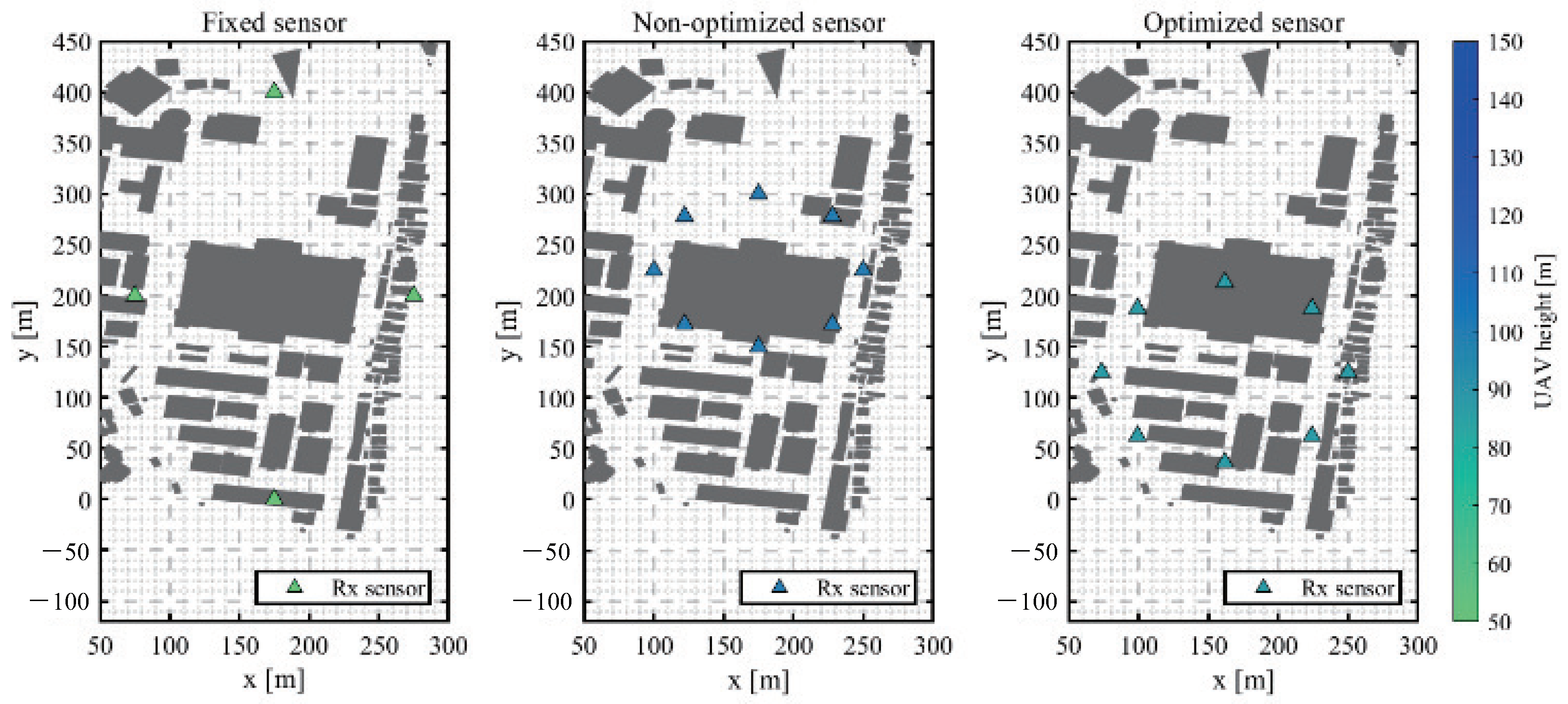
Using the created fingerprint database, localization simulations are performed to determine the flight paths of UAVs that can perform localization with higher accuracy.
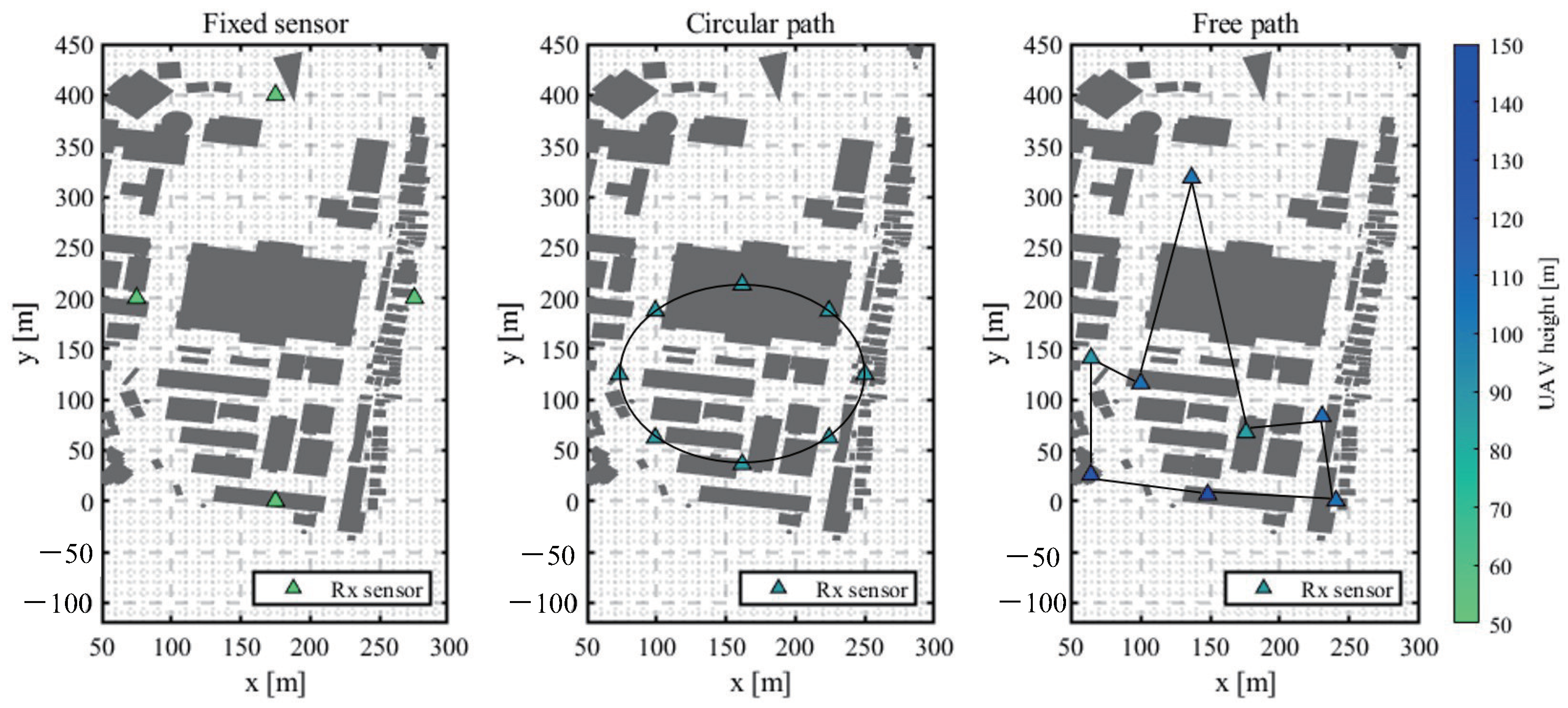
The determination of UAV flight paths can be viewed as an optimization problem that aims to minimize the 90th percentile of the cumulative distribution of localization errors as our designed objective function. In order to study the effect of using UAVs, this paper examines the case where UAV sensors are hovering in the air and the case where a single UAV moves in a circular orbit. In the former case, the position coordinates of the sensors are used as input variables, and in the latter case, the position coordinates of the center of the circular orbit and the radius of the circular orbit are used as input variables.
The RSSI used to evaluate the localization error is generated according to a probability distribution and is affected by the terrain, so the output of the objective function is a nonlinear function. In addition, the position coordinates take continuous values in space, and there are many different ways to take a path, making optimization by a full search difficult. Therefore, as explained in Appendix A, the particle swarm optimization (PSO) method is used as an approximate solution method that is compatible with nonlinear systems [19,20]. Given an objective function to be searched for, multiple particles move around in the search space in search of the optimal solution while sharing information with each other. PSO has attracted attention because of its simple algorithm, flexible parallel processing, and potential for various improvements [21]. It also works well with nonlinear systems and is suitable for cases such as this study.
Based on the basic algorithm of PSO, we organize the optimization problem in this study. The optimization problem is to find the UAV sensor position coordinates u that minimize E ( u ) with the 90 % cumulative distribution value of localization errors as the objective function E ( u ) . In this study, the CDF 90 % value is used as an indicator of reliability as a location estimation system, but the objective function in this algorithm can be flexibly set according to the system designer’s policy [11].
min u E ( u ) , u = ( u 1 , , u M ) Γ
Here, Γ is the three-dimensional space that can be taken by the UAV sensor, and u is normalized so that each element is 0 u 1 . The position and velocity of the particles are updated by the following equations, respectively [11].
u i ( t + 1 ) = u i ( t ) + v i ( t + 1 )
v i ( t + 1 ) = w v i ( t ) + c 1 u i pbest u i ( t ) + c 2 u i gbest u i ( t ) ,
where t is the number of iterations to date, u i pbest ( t ) is the personal best, and u i gbest ( t ) is the value called the global best. The personal best is the particle position with the best value to date for that particle, and the global best is the best value of the personal best for all particles. The particle moves and searches for the optimal solution by iteratively updating t MAX times, referring to the direction of the personal best and global best. The PSO parameters used in this paper are listed in Table 3.

4. Simulation Results

In this simulation, we compare the position estimation results from a ground-sensor-mimicking fixed sensor, a non-optimized UAV sensor, and an optimized UAV sensor. First we discuss an optimized route where the UAV is restricted to follow a circular orbit in Section 4.1. Then, the restriction is removed and an optimized free-path orbit is investigated in Section 4.2.

4.1. Circular Orbit Optimization

The fixed sensors were installed at four locations at appropriate heights of 50 m in the east, west, south, and north area of the evaluation environment. The non-optimized UAV sensor draws a circular orbit with a radius of 75 m and an altitude of 100 m near the center of the target area. The optimized UAV sensor draws a circular orbit with the center coordinates and radius optimized.
The placement of the fixed and non-optimized UAV and optimized UAV sensors and the localization error distribution are shown in Figure 8 and Figure 9, respectively. It can be seen that when fixed sensors and non-optimized UAV are used a significant degradation of localization accuracy can be observed in zones with dense buildings, while relatively good accuracy is obtained overall when UAV sensors are used.
Next, the cumulative distribution function (CDF) of localization accuracy is shown in Figure 10. Comparing the CDF 90 % values, the value for the fixed sensor is 55.02 m and the value for the non-optimized UAV sensor is 77.96 m, whereas the value for the optimized UAV is 28.59 m, as shown in Table 4.
In other words, our proposed system reduced 48 % of localization error compared to the conventional scheme at our designed target of 90th percentile CDF. This confirms that a single optimized UAV sensor provides better localization accuracy than four fixed base stations, which reveals the superiority of our proposed method.

4.2. Non-Circular Orbit Optimization

To further explore the mobility freedom of the UAV sensor, next, we discuss the results of the optimization of the non-circular orbit optimization. Eight patrol points are selected, and the coordinates including the altitude of those points are optimized. Figure 11 and Figure 12 show the optimized patrol points of receiver sensor route and the corresponding estimation errors, respectively. Compared to the circular path on which the UAV’s patrol points are restricted to a certain circle of optimized radius, the patrol points of the free-path case have more freedom to visit the whole area to collect more reliable RF fingerprints, knowing that the RSSI fingerprints in this paper might be contaminated by noise, especially when the distance between the UAV sensor and the emitter is long, the path is obstructed by buildings, etc. Since the patrol points of the circular path are restricted on a specific circle, even after the optimization process, some patrol points need to fly over the rooftop of a big building in the center area of the map. Since this building has a higher probability of obstructing most of the propagation path between these patrol points and emitters (i.e., NLoS environments), the localization estimation accuracy of the circular path is expected to be poorer than that of the free path. Indeed, it can be seen from the result of the free-path optimization that one patrol point is selected in the northern area where it is easy to secure an LoS, and some other patrol points are concentrated in the southern area with a denser distribution of buildings that made the environment more multipath vulnerable. As a result, it is easier to secure an LoS condition compared to both scenarios of fixed sensors and circular orbits evaluated in Section 4.1. Owing to this benefit, the position estimation error is not degraded even in areas where buildings are densely populated.
Next, the cumulative distribution function (CDF) of the position estimation error is shown in Figure 13 and Table 5. Compared with the CDF value of 90%, which is the objective function set in this study, the error is 55.02 m for the fixed sensor and 28.59 m for the circular orbit UAV sensor, while it is 12.91 m for the UAV sensor with optimized patrol points. Thus, it can be seen that the position estimation accuracy is further improved compared to the case of optimization with a circular orbit.

5. Conclusions

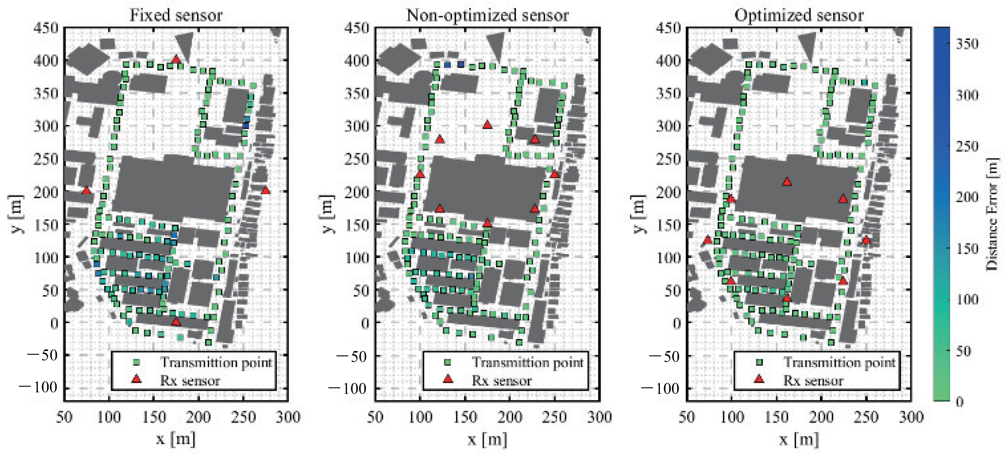
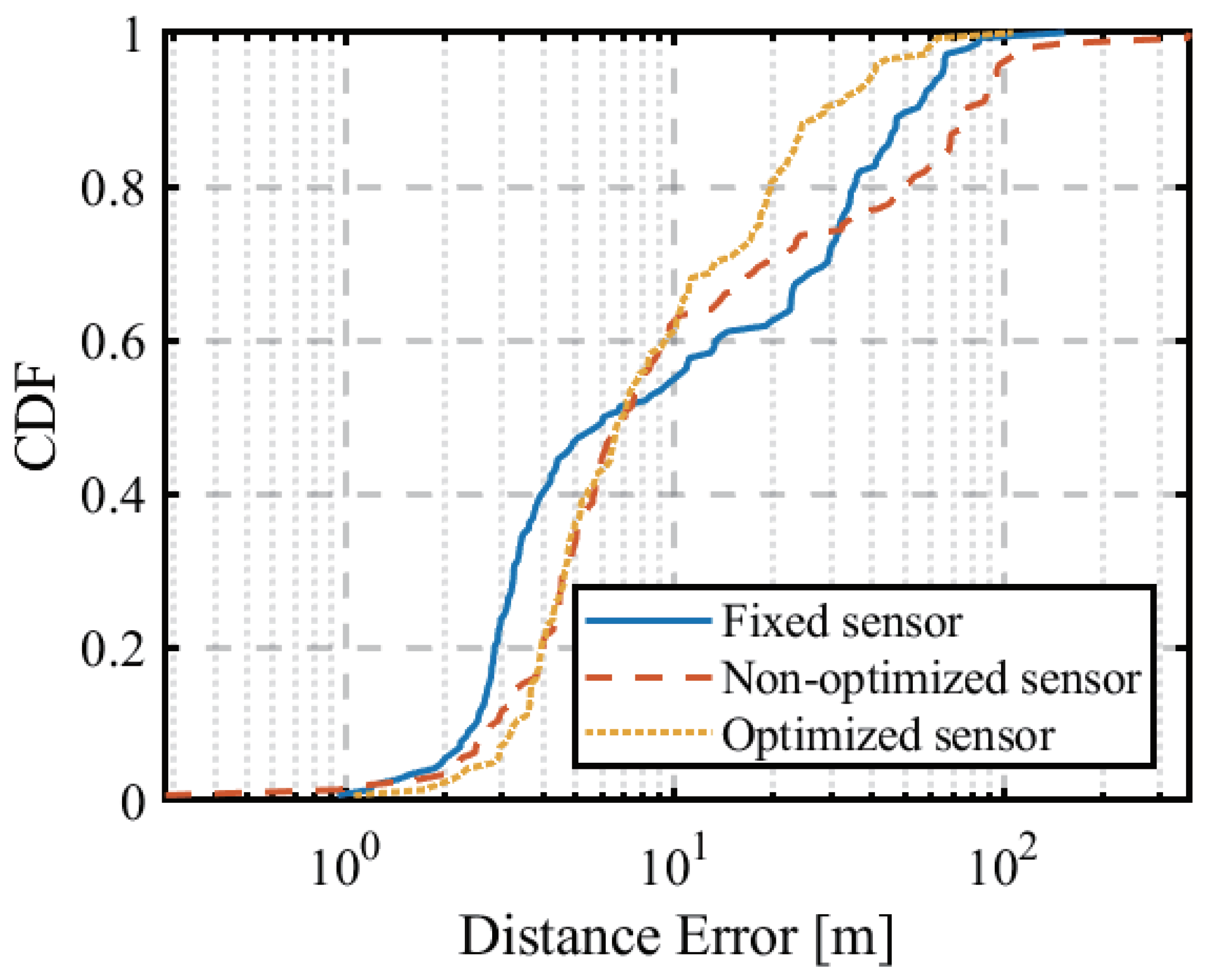
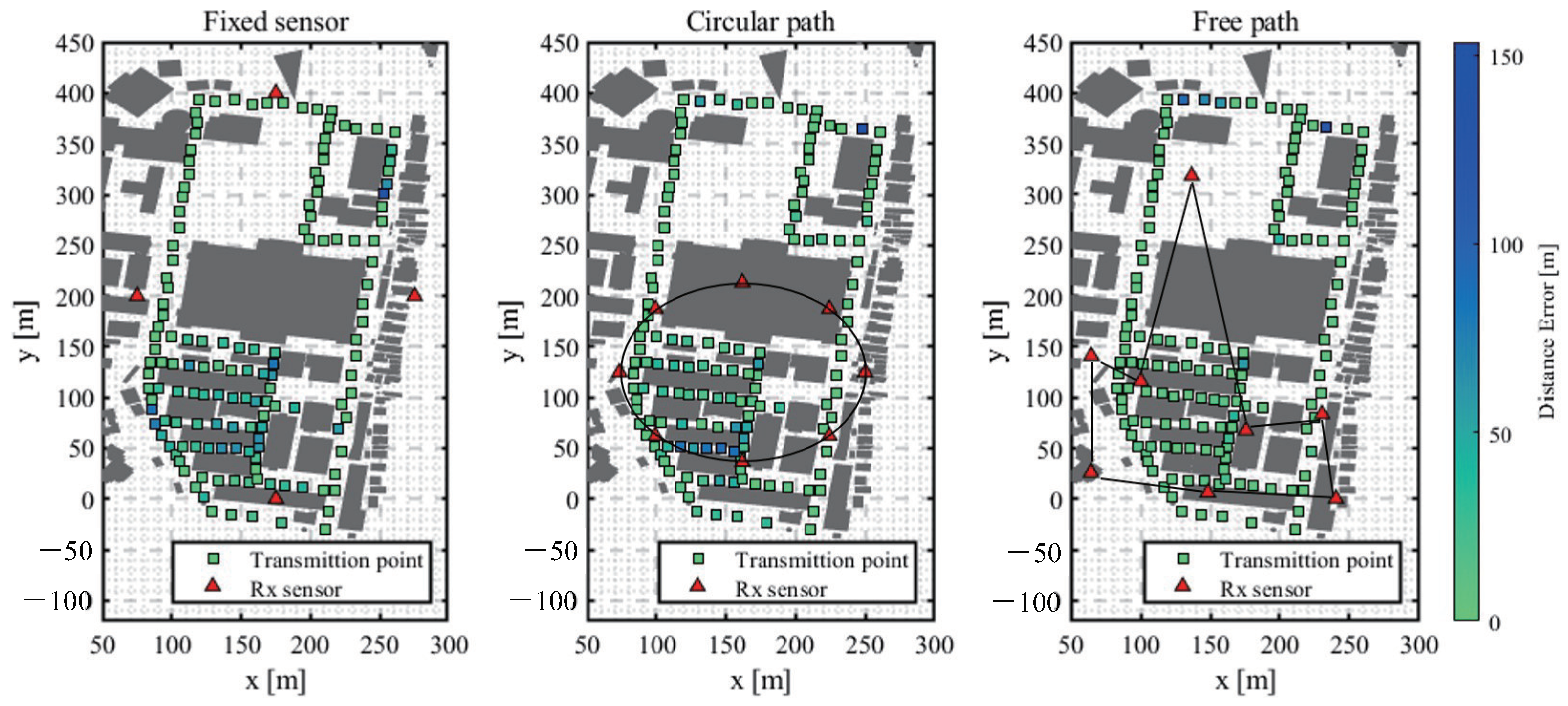
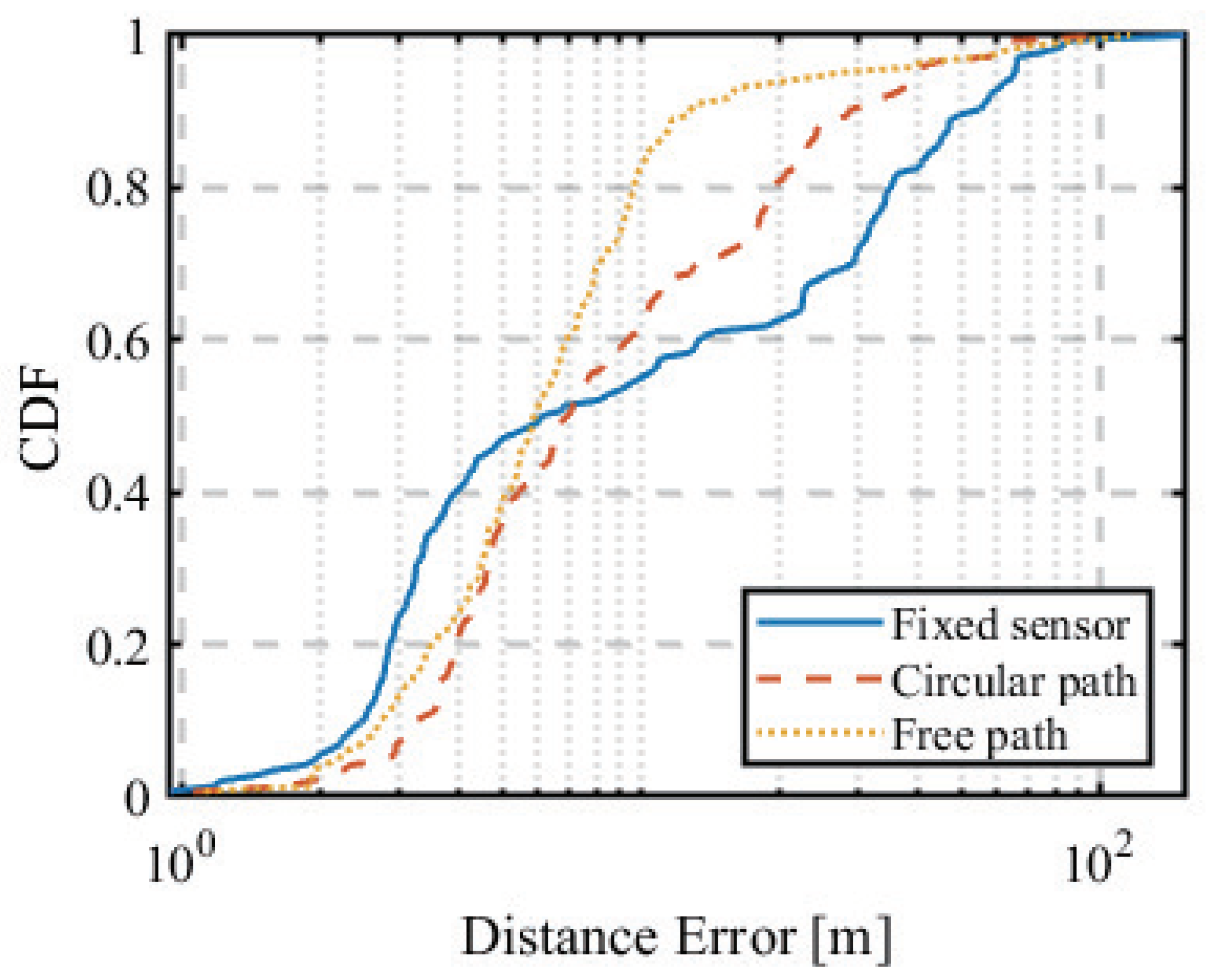
In this paper, we constructed a fingerprint database using ray-traced simulation and model-based interpolation and conducted numerical analyses to optimize the flight path of UAV sensors by evaluating the localization error via PSO for two scenarios, a circular orbit and a free-path orbit. Comparison with fixed sensors installed on the ground showed that UAV sensors can be used for low-cost and highly accurate outdoor localization. Our numerical results revealed the superiority of the proposed optimized routes, especially when the UAV can fly freely in the case of non-circular orbit. Specifically, our numerical results reveal the improved localization estimation error performance of our proposed approach. When evaluating at the 90th percentile of the error’s cumulative distribution function (CDF), the proposed approach can reach an error of 28.59 m with a circular orbit and 12.91 m with a free-path orbit, as compared to the conventional fixed sensor case whose localization estimation error is 55.02 m.
Since the presented mechanism is general and not only for illegal emitters, the extension of the proposed localization method to authorized (non-illegal) radios is straightforward [4]. However, deploying a UAV sensor for localization purposes in practical environments is expected to face a lot of challenges, including power constraints, energy-efficient route planning, UAV self-localization issues, and security aspects [22,23]. Such practical considerations will be investigated in our future works. Furthermore, our future prospects also include the development of advanced optimization algorithms and the location estimation of moving radio sources to realize a system capable of tracking and policing illegal radio stations and experimental validations of the proposed technology in realistic environments.

Author Contributions

Conceptualization, G.K.T., T.K. and S.T.; methodology, T.K. and G.K.T.; software, T.K.; validation, T.K. and G.K.T.; formal analysis, T.K.; investigation, T.K. and G.K.T.; resources, G.K.T. and S.T.; data curation, T.K.; writing—original draft preparation, T.K. and G.K.T.; writing—review and editing, G.K.T.; visualization, T.K.; supervision, G.K.T. and S.T.; project administration, G.K.T. and S.T.; funding acquisition, G.K.T. and S.T. All authors have read and agreed to the published version of this manuscript.

Funding

This research received no external funding.

Data Availability Statement

Not applicable.

Acknowledgments

We would like to thank the anonymous reviewers for their careful reading of our manuscript and their many insightful comments and suggestions to improve the quality of this manuscript.

Conflicts of Interest

The authors declare no conflict of interest.

Appendix A. Optimization Problem Solving

This section discusses methods for solving the UAV flight path optimization problem of this paper. The objective function of this problem is difficult to optimize using a gradient method since the objective function’s shape varies greatly depending on the environment’s terrain and scattering objects. In addition, the huge computational complexity involved in simulating radio propagation makes the use of heuristics methods suitable for obtaining a good approximation of the solution, even if there is no guarantee of optimality. Meta-heuristics is a strategy to further improve the approximate solution obtained by heuristics by modifying the solution to get closer to the optimal one. In meta-heuristics approaches, the solution space is explored by iteratively (1) generating new solutions using the previous search history and (2) evaluating the generated solutions and feeding back the necessary information for the next solution search. In this paper, we focus on particle swarm optimization (PSO) and the genetic algorithm (GA) among these meta-heuristics. Since PSO was explained in Section 3.4, the following paragraph briefly explains about GAs.
Genetic algorithms (GAs) are algorithms that search for solutions in a manner that mimics the mechanism of biological evolution. A population of chromosomes with genetic parameters is generated as candidate solutions, and genetic manipulations such as selection, crossover, and mutation are performed to search for solutions [24]. First, an initial population of genes is generated. Next, the degree of adaptation is evaluated according to the evaluation function. If the function meets the termination condition, the process is terminated. Otherwise, genetic manipulations, such as selection, crossover, and mutation, are performed, and the next generation is used to repeat the above process until the termination condition is satisfied and the optimal solution is obtained. The Parameters of GA in this paper is summarized in Table A1.
Table A1. GA parameters.
ParameterValue or Property
Initial population U ( 0 , 1 )
Number of genes50
Iteration10
Generation modelDiscrete
SelectionRoulette
CrossoverOne-point crossing
Mutation probability0.01
We compare the accuracy of the aforementioned optimization methods, assuming eight fixed hovering UAV sensors are employed (It is equivalent to a single UAV flying with a free-path trajectory and visiting these locations consequently). Figure A1 and Figure A2 show the placement of the receiving sensors and the distribution of the position estimation error, for three scenarios of random deployment and optimized deployments using PSO and a GA, respectively. The CDF of the position estimation error is shown in Figure A3. These results reveal that the localization estimation errors of the optimized schemes are reduced significantly compared to the random placement case. Particularly, the performance of PSO is better than the GA, so we decided to use PSO as the optimization method in this paper.
Figure A1. Locations of hovering UAV sensors (optimization algorithm comparison).
Network 03 00016 g0a1
Figure A2. Localization error map (optimization algorithm comparison).
Network 03 00016 g0a2
Figure A3. CDF of localization error (optimization algorithm comparison).
Network 03 00016 g0a3

References

  1. Farhan, L.; Hameed, R.S.; Ahmed, A.S.; Fadel, A.H.; Gheth, W.; Alzubaidi, L.; Fadhel, M.A.; Al-Amidie, M. Energy Efficiency for Green Internet of Things (IoT) Networks: A Survey. Network 2021, 1, 279–314. [Google Scholar] [CrossRef]
  2. Ministry of Internal Affairs and Communications Japan DEURAS Direction Finder (DEURAS-D). Available online: https://www.tele.soumu.go.jp/e/adm/monitoring/moni/type/deurasys/deuras_d.htm (accessed on 26 July 2023).
  3. Witrisal, K. Inclusive Radio Communications for 5G and beyond; Science Direct; Academic Press: Washington, DC, USA, 2021; Chapter 9; pp. 253–293. [Google Scholar]
  4. Haniz, A. Fingerprint-Based Localization of Unknown Radio Emitters in Outdoor Urban Environments. Ph.D. Thesis, Tokyo Institute of Technology, Tokyo, Japan, 2016. [Google Scholar]
  5. Yu, T.; Haniz, A.; Sano, K.; Iwata, R.; Kosaka, R.; Kuki, Y.; Tran, G.K.; Takada, J.; Sakaguchi, K. A guide of fingerprint based radio emitter localization using multiple sensors. IEICE Trans. Commun. 2018, 101, 2104–2119. [Google Scholar] [CrossRef]
  6. Murata, S.; Matsuda, T.; Nishimori, K. Maximum likelihood estimation for single wave source localization using multiple UAVs in NLOS environments. IEICE Trans. Commun. 2022, 105, 229–239. (In Japanese) [Google Scholar]
  7. Vo, Q.D.; De, P. A Survey of Fingerprint based Outdoor Localization. IEEE Commun. Surv. Tutor. 2015, 18, 491–506. [Google Scholar] [CrossRef]
  8. Bahl, P.; Padmanabhan, V. RADAR: An in-building RF-based user location and tracking system. In Proceedings of the IEEE INFOCOM 2000, Tel Aviv, Israel, 26–30 March 2000; Volume 2, pp. 775–784. [Google Scholar]
  9. Li, B.; Wang, Y.; Lee, H.; Dempster, A.; Rizos, C. Method for yielding a database of location fingerprints in WLAN. IEE Proc.-Commun. 2005, 152, 580–586. [Google Scholar] [CrossRef]
  10. Tanaka, S.; Tran, G.K.; Sakaguchi, K. Outdoor Localization of RF Emitter Using UAV-based Sensors. In Proceedings of the IEICE SmartCom2019, New Brunswick, NJ, USA, 18–20 November 2016. [Google Scholar]
  11. Kamei, T.; Tran, G.K.; Tanaka, S. Study on the Optimization of Flight Paths for Fingerprint-Based Outdoor Localization Using UAV. In Proceedings of the IEEE PIMRC, Tokyo, Japan, 12–15 September 2022. [Google Scholar]
  12. Alsheikh, M.A.; Lin, S.; Niyato, D.; Tan, H.P. Machine Learning in Wireless Sensor Networks: Algorithms, Strategies, and Applications. IEEE Commun. Surv. Tutor. 2014, 16, 1996–2018. [Google Scholar] [CrossRef]
  13. Alzubaidi, L.; Bai, J.; Al-Sabaawi, A.; Santamaría, J.; Albahri, A.S.; Al-dabbagh, B.S.N.; Fadhel, M.A.; Manoufali, M.; Zhang, J.; Al-Timemy, A.H.; et al. A survey on deep learning tools dealing with data scarcity: Definitions, challenges, solutions, tips, and applications. Big Data 2023, 10, 46. [Google Scholar] [CrossRef]
  14. Tanaka, S. Study on Sensor Positions for Outdoor Localization of RF Emitter Using UAV-Based Sensors. Master’s Thesis, Tokyo Institute of Technology, Tokyo, Japan, 2020. (In Japanese). [Google Scholar]
  15. Tsuchiya, K. UAV-Based Outdoor Location Estimation Technology Using Time-Series Fingerprinting Method. Master’s Thesis, Tokyo Institute of Technology, Tokyo, Japan, 2022. (In Japanese). [Google Scholar]
  16. Imai, T. Ray-Tracing Method for Radio Propagation Analysis—Fundamentals and Practical Applications; Corona Publishing Co.: Tokyo, Japan, 2016. (In Japanese) [Google Scholar]
  17. Haniz, A.; Tran, G.K.; Iwata, R.; Sakaguchi, K.; Takada, J.; Hayashi, D.; Yamaguchi, T.; Arata, S. Propagation Channel Interpolation for Fingerprint-Based Localization of Illegal Radio. IEICE Trans. Commun. 2015, 98, 2508–2519. [Google Scholar] [CrossRef]
  18. Holis, J.; Pechac, P. Elevation dependent shadowing model for mobile communications via high altitude platforms in built-up areas. IEEE Trans. Antennas Propag. 2008, 56, 1078–1084. [Google Scholar] [CrossRef]
  19. Kennedy, J.; Eberhart, R. Particle swarm optimization. In Proceedings of the ICNN’95—International Conference on Neural Networks, Perth, Australia, 27 November–1 December 1995. [Google Scholar]
  20. Shimizu, Y. An Encouragement of Learning Optimization Engineering—Workbench for Smart Decision Making; Corona Publishing Co.: Tokyo, Japan, 2010. (In Japanese) [Google Scholar]
  21. Saito, T. Particle Swarm Optimizers and Nonlinear Systems. IEICE-ESS Fundam. Rev. 2011, 5, 155–161. (In Japanese) [Google Scholar] [CrossRef]
  22. Krichen, M.; Adoni, W.Y.H.; Mihoub, A.; Alzahrani, M.Y.; Nahhal, T. Security Challenges for Drone Communications: Possible Threats, Attacks and Countermeasures. In Proceedings of the 2022 2nd International Conference of Smart Systems and Emerging Technologies (SMARTTECH), Riyadh, Saudi Arabia, 9–11 May 2022; pp. 184–189. [Google Scholar]
  23. Ko, Y.; Kim, J.; Duguma, D.G.; Astillo, P.V.; You, I.; Pau, G. Drone Secure Communication Protocol for Future Sensitive Applications in Military Zone. Sensors 2021, 21, 2057. [Google Scholar] [CrossRef] [PubMed]
  24. Man, K.F.; Tang, K.S.; Kwong, S. Genetic algorithms: Concepts and applications. IEEE Trans. Ind. Electron. 1996, 43, 519–534. [Google Scholar] [CrossRef]
Figure 1. Statistics of illegal radios in Japan [2].
Network 03 00016 g001
Figure 2. Two phases of fingerprint-based localization method.
Network 03 00016 g002
Figure 3. Outdoor localization using UAV.
Network 03 00016 g003
Figure 4. Simulation system overview.
Network 03 00016 g004
Figure 5. Simulation terrain model.
Network 03 00016 g005
Figure 6. Horizontal positions of the transmitter and UAV sensor candidate points.
Network 03 00016 g006
Figure 7. Model parameter determination by regression (top row: μ n , σ n and bottom row: μ s , σ s ).
Network 03 00016 g007
Figure 8. Optimized sensor placement (circular orbit).
Network 03 00016 g008
Figure 9. Localization error distribution (circular orbit).
Network 03 00016 g009
Figure 10. CDF of localization error (circular orbit).
Network 03 00016 g010
Figure 11. Patrol points of UAV sensor (non-circular orbit).
Network 03 00016 g011
Figure 12. Localization error map (non-circular orbit).
Network 03 00016 g012
Figure 13. CDF of localization error (non-circular orbit).
Network 03 00016 g013
Table 1. Summary of abbreviations used in this manuscript.
AbbreviationMeanings
LoSLine-of-Sight
NLoSNon-Line-of-Sight
UAVUnmanned Aerial Vehicle
PSOParticle Swarm Optimization
GAGenetic Algorithm
RFRadio Frequency
MICMinistry of Internal Affairs and Communications
DEURASDetect Unlicensed Radio Stations
DEURAS-DDEURAS Direction Finder
GPSGlobal Positioning System
RSSIReceived Signal Strength Indicator
TDOATime Difference of Arrival
AOAAngle of Arrival
FDTDFinite-Difference Time-Domain
TxTransmitter
RxReceiver
CDFCumulative Density Function
NNSSNearest Neighbour in Signal Space
KNNk-Nearest Neighbour
MLMaximum Likelihood
Table 2. Ray-tracing parameters.
RxAntenna type
Antenna height (m)
Isotropic
50/75/100/125/150
TxFrequency (GHz)2.487
Bandwidth (MHz)5.00
Transmit power (dBm)27.0
Antenna typeIsotropic
Antenna height (m)2
IterationReflection6
Diffraction1
Penetration0
Table 3. Parameters of PSO.
u i ( 0 ) , v i ( 0 ) w c 1 , c 2 Number of Particles t MAX
U ( 0 , 1 ) 0.5 U ( 0 , 0.14 ) 10010
Table 4. Comparison of localization error (circular orbit).
SensorAverage (m)CDF 90% (m)
Fixed19.6955.02
Non-optimized28.1877.96
Optimized13.0928.59
Table 5. Comparison of localization error (non-circular orbit).
SensorAverage [m]CDF 90% [m]
Fixed19.6955.02
Circular orbit13.0928.59
Non-circular orbit9.6612.91
Disclaimer/Publisher’s Note: The statements, opinions and data contained in all publications are solely those of the individual author(s) and contributor(s) and not of MDPI and/or the editor(s). MDPI and/or the editor(s) disclaim responsibility for any injury to people or property resulting from any ideas, methods, instructions or products referred to in the content.

