1. Introduction
Changes in rainfall are one of the most critical factors in determining the overall impact of climate change. The hydrological cycle has intensified with global warming, which likely increases the intensity of extreme precipitation events [
1]. Due to climate change and increased rainfall, an adaptation of the drainage is required [
2] to prevent natural disasters caused by water. It is well known that water is one of the major triggers of landslides, especially shallow landslides or “soil slips” [
3]. Shallow landslides are phenomena triggered by rainfall events with short duration and high intensity or with long duration and medium–low intensity [
4,
5,
6,
7,
8]. Water may have different effects on slope stability: decreasing suction, rising groundwater table and subsequent increasing pore water pressure, groundwater exfiltration from the bedrock, seepage erosion, hydraulic uplift pressure from below the landslide, and influence of water on the plasticity of the landslide [
9,
10,
11]. Which of those processes is dominant in causing triggering depends on the geological and hydrogeological characteristics of the site. However, the analysis of slope stability requires geotechnical input parameters. The condition of the subsurface soil on landslides is determined by the standard soil investigative techniques with borehole drilling, sampling and laboratory sample testing, along with electrical and seismic geophysical surveys. In recent years, standard research methods have often been supplemented by modern in situ geotechnical tests such as the Cone Penetration Test and Flat Dilatometer Test [
12].
Extreme weather conditions in the winter and spring of 2013 (re)activated more than 900 shallow landslides in North-Western Croatia [
13]. Croatia’s neighboring countries, Slovenia and Italy, also face frequent landslides [
14,
15,
16,
17,
18]. That is why quantitative methodology for zoning the susceptibility of slopes to landslides is increasingly being used [
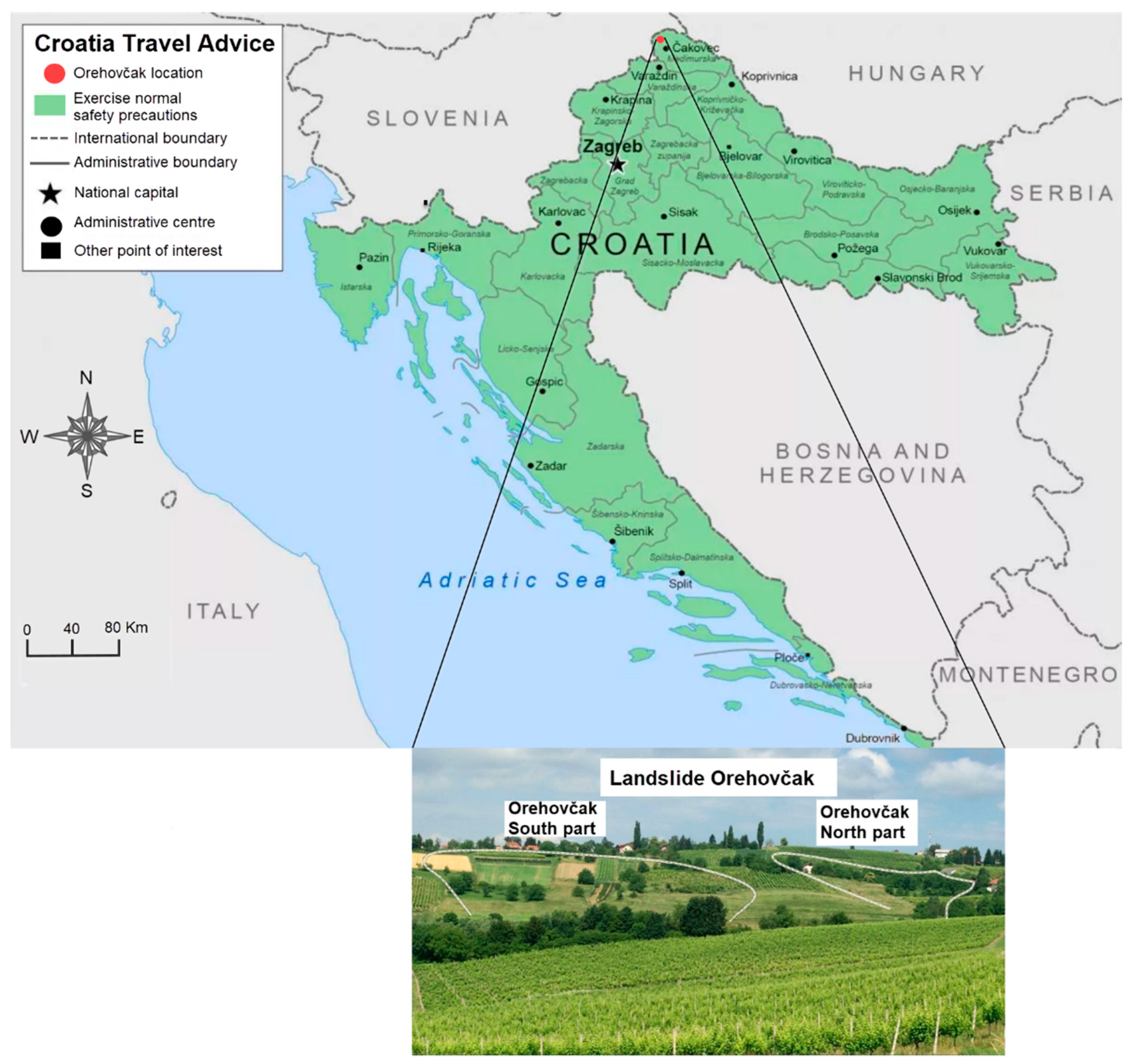
19]. The landslide “Orehovčak” is a typical example of a shallow landslide induced by rainwater infiltration. At the beginning of 2018, instability was observed on the slope covered with agricultural land. The study area of about 11 hectares is located in Northern Croatia, Međimurje County (
Figure 1). The local authorities decided to launch a project to rehabilitate and remedy landslide failures. To characterize the subsurface soil conditions, investigations were conducted in six phases [
20].
The authors had at their disposal different techniques for slope remediation, such as the following: slope regarding, retaining structures, structural reinforcement, vegetation and bioengineering, etc. However, the remedial work had to include drainage, so methods involving the construction of boreholes, wells and water removal techniques were considered. After technical and economic analyses in cooperation with investors, methods using vertical boreholes for self-draining, vertical wells for gravity draining, sub-vertical and sub-horizontal boreholes, drainage tunnels and galleries were rejected.
Slope stabilization was completed in 2020 by reducing the amount of water in the landslide body. This is achieved by a system of digging drains (deep trench drains), which have been shown to be effective in lowering groundwater potential.
2. Materials and Methods
2.1. Geological Observing and Mapping
Geological investigations of the slopes are very important, especially if there is a danger of slipping on the road [
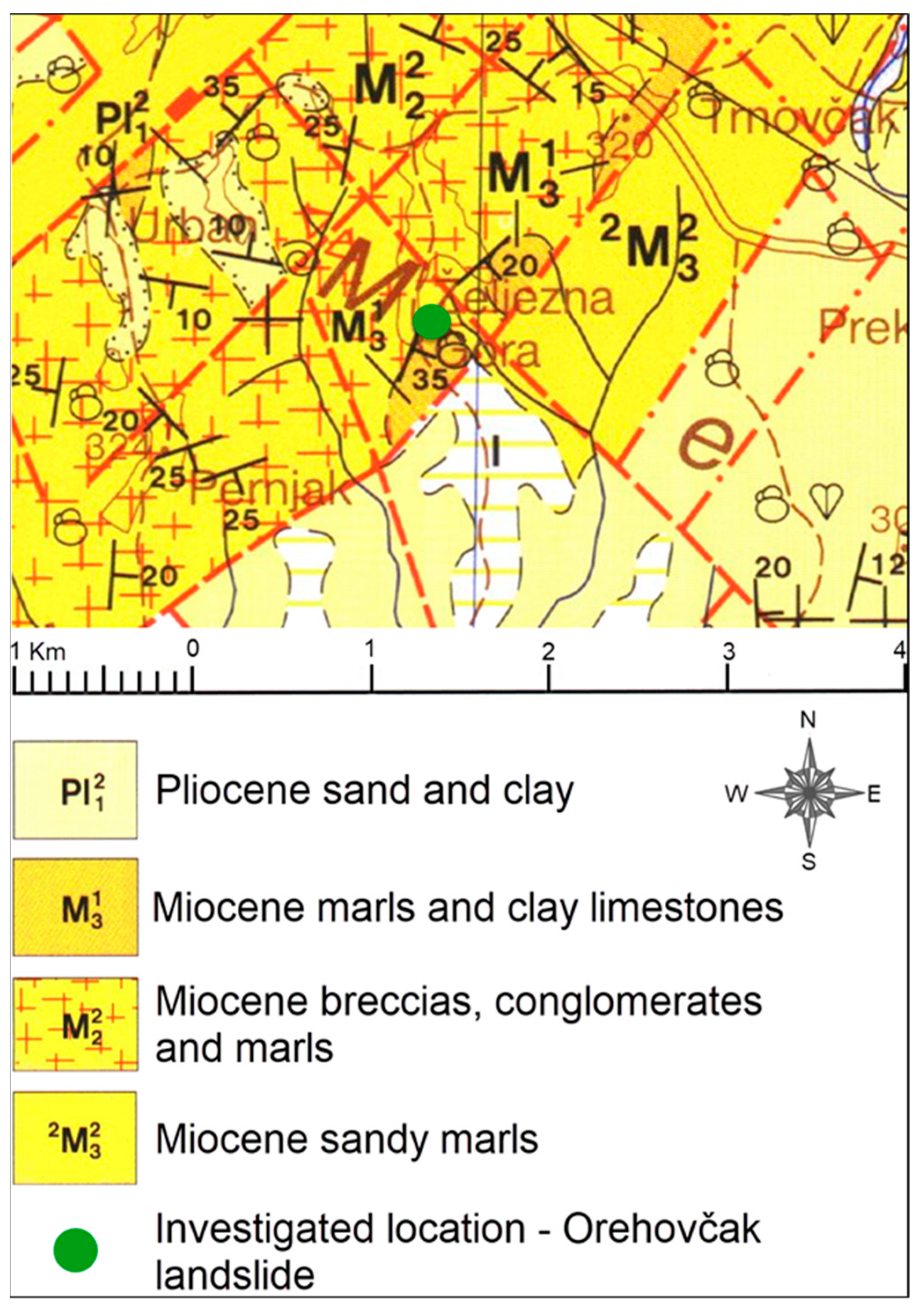
22]. Geological mapping had already begun in the office. All available geological reports and data, including satellite photographs, topographical maps, basic maps, legislative boundary maps, etc., were reviewed. An inspection of the hill showed that the slope profile is modest, at an angle of about 25 degrees. However, the author’s previous experiences have shown that a gentle slope is actually a frequent prerequisite for the formation of a shallow landslide. Continuation of geological research was carried out in the field to collect additional data. These data were collected in the form of photographs, measurements and notes. In the cuts of local roads, it was partly discovered that the terrain was practically entirely covered by the products of weathering of rocks from the substrate, in geological terms. The geological map [
23] and geological map interpreter [
24] for the wider area indicate the presence of geological materials from the Miocene and Pliocene. Part of the mentioned geological map is shown in
Figure 2. The geological profile that crosses the landslide area is shown in the geological observing and mapping results.
2.2. Geotechnical Reconnaissance
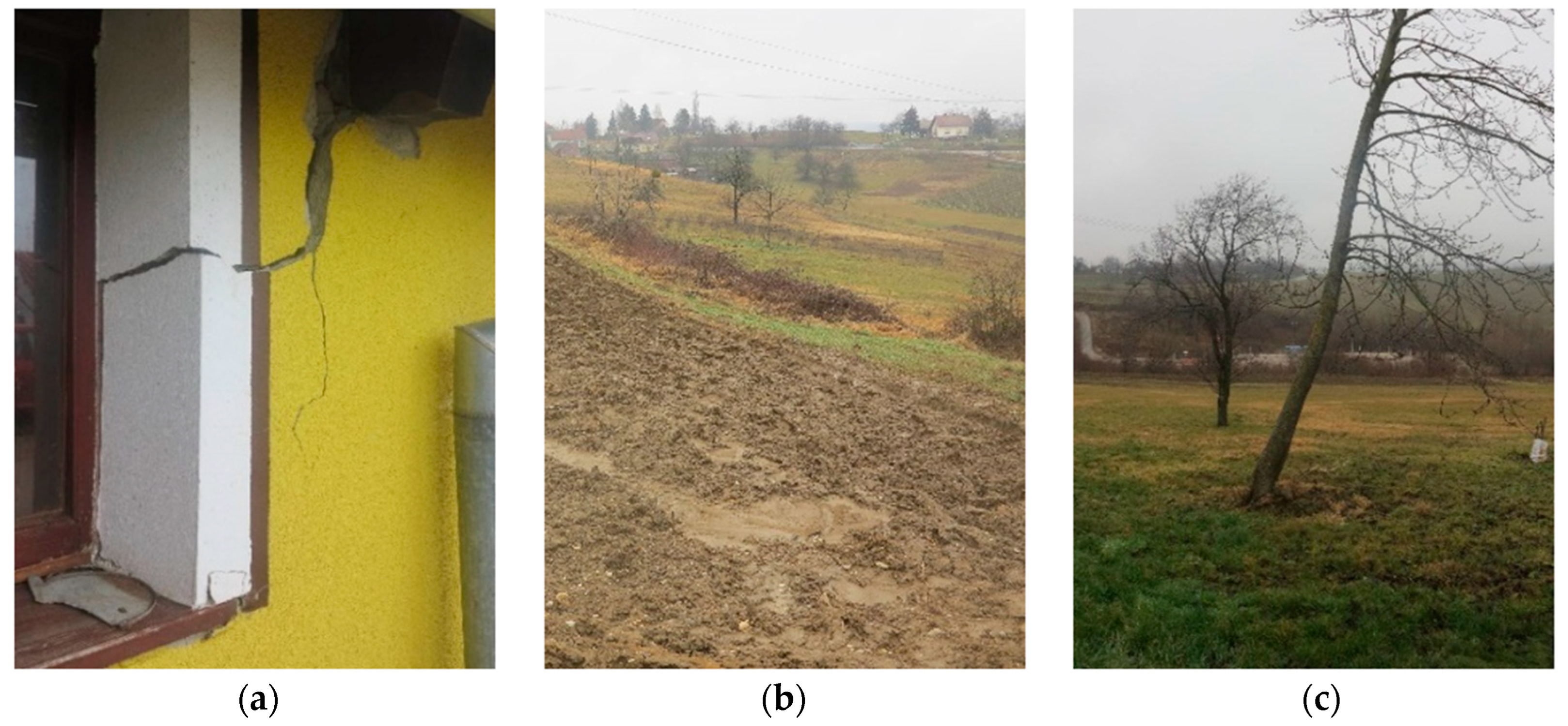
Geotechnical reconnaissance of the unstable area was conducted in order to determine the character, intensity and coverage of the unstable slope zone. Visible occurrences and reported information of local residents were carefully recorded. The consequences of soil movement were clearly visible on the buildings located at the top of the slope (
Figure 3a). In parts of the slope, intensive soil moisture was noticed, which in those parts turns the agricultural area into a muddy mass (
Figure 3b) and causes tilting of trees (
Figure 3c).
2.3. Geophysical Investigations
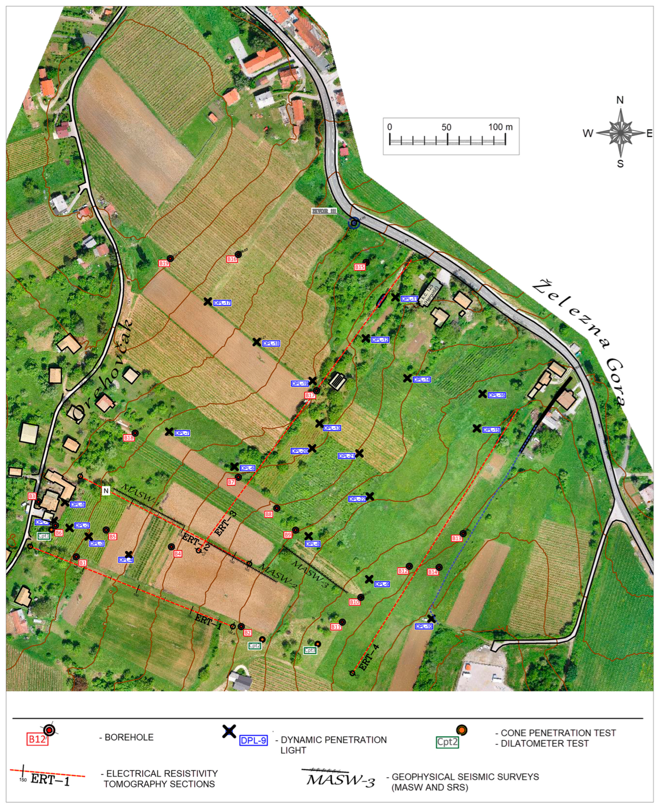
The geophysical investigations were performed utilizing three techniques: Electrical Resistivity Tomography (ERT), Shallow Seismic Refraction Survey (SRS) and Multichannel Analysis of Surface Waves (MASW). The position of geophysical surveys is shown in
Figure 4.
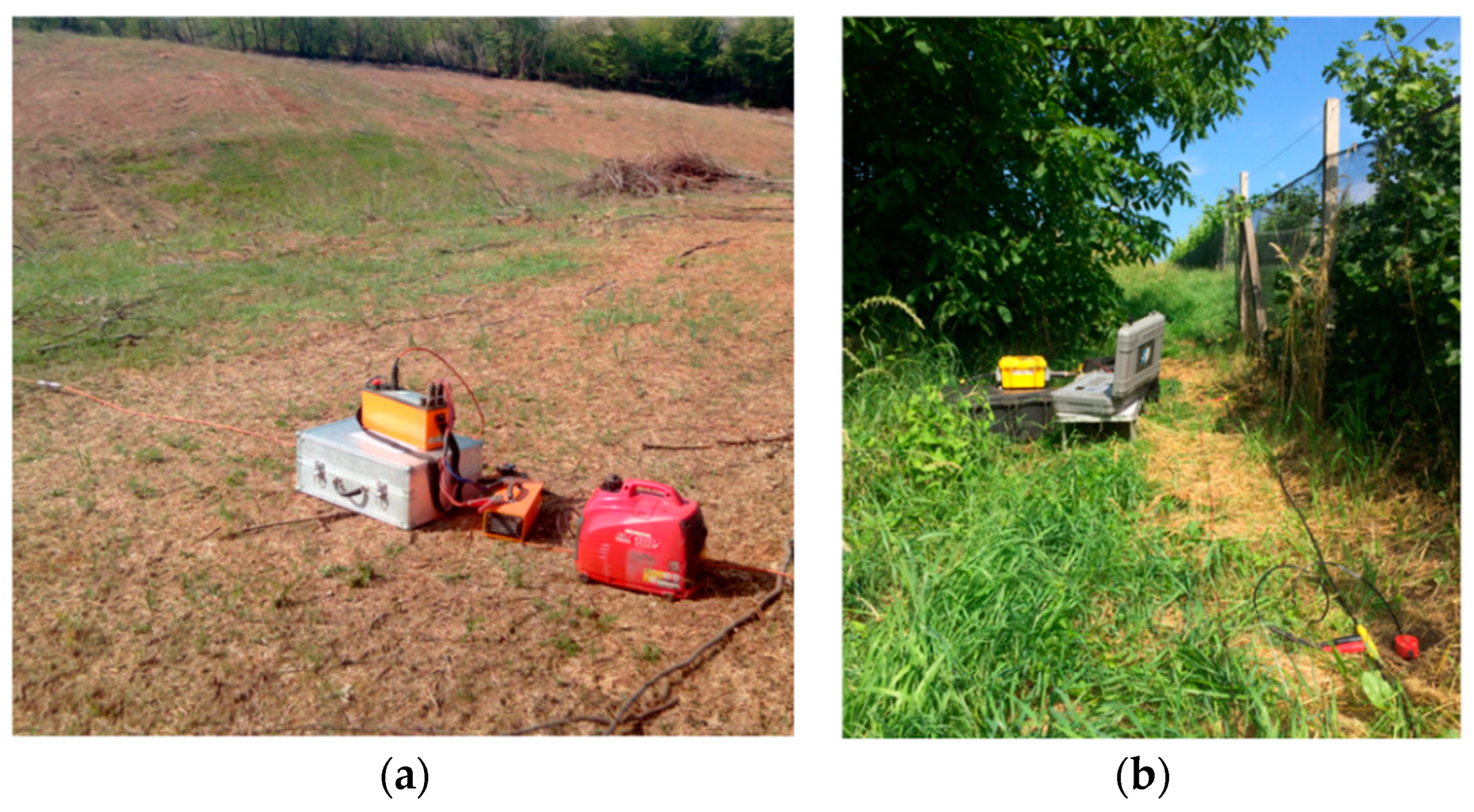
ERT is a geophysical technique that generates 2D pictures depicting the distribution of electrical resistivity in the subsurface [
12].
Figure 5a displays the ARES system (Czech manufacturer GF Instruments), which is a multi-electrode system used for 2D electric study. This technique utilizes an array of electrodes interconnected by multicore cable to generate a linear depth profile, or pseudo section, of the resistivity variation along the survey line and at different depths. This procedure is well described in [
25]. The analysis and interpretation of tomograms enable the detection of variations in resistivity, which can be caused by differences in lithological material or changes in water content within certain areas [
12]. The inversion of the resistivity profile was successfully performed via the RES2DINV version 4.02 software, which is based on the methodology given by Loke [
26].
The primary seismic approach used in seismic tomography is SRS, which primarily utilizes seismic P-waves. However, it comes with some disadvantages [
27]. MASW, first introduced in 1999 [
28], is a seismic exploration technique for mapping the subsurface. The MASW technique initially detects seismic Rayleigh surface waves created by different seismic sources, analyzes the velocities at which these surface waves propagate, and later indicates variations in shear wave velocity (V
S) below the surveyed zone. The field techniques and data processing steps are concisely described in [
29]. The GEODE investigation seismograph (Geometrics) and 24 geophones with a frequency of 4.5 Hz with a spacing of 3 m were utilized for imaging in Orehovčak (
Figure 5b). The collected data were analyzed using the PC software SeisIMAGER 4.0.1.6. developed by OYO Corporation.
2.4. Geotechnical Investigations
The position of geotechnical surveys is also shown in
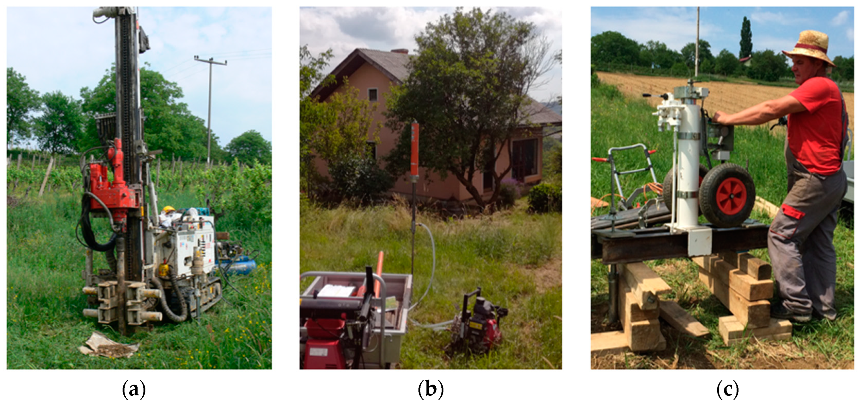
Figure 4. Nineteen boreholes (a total of 100 m of drilling) were carried out using the rig boring machine Comacchio Geo 205 (
Figure 6a), completed by laboratory testing soil samples from the boreholes. To supplement the information obtained from exploratory core drilling, additional in situ tests were carried out. In situ geotechnical testing is a rapid and uninterrupted process that yields instant data, which can be quickly utilized for analysis purposes.
The initial step involved soil testing using the Dynamic Probe Light (DPL) method, where a probe cone was forcefully driven into the ground by a 10 kg hammer dropped from a height of 50 cm. Dynamic penetration resistance is defined as the number of blows to penetrate 10 cm. Dynamic probe testing was modified in [
30]. On the landslide Orehovčak, 22 dynamic probes were made with Nordmeyer Geotool PR 30 (
Figure 6b) up to a maximum depth of 7.5 m.
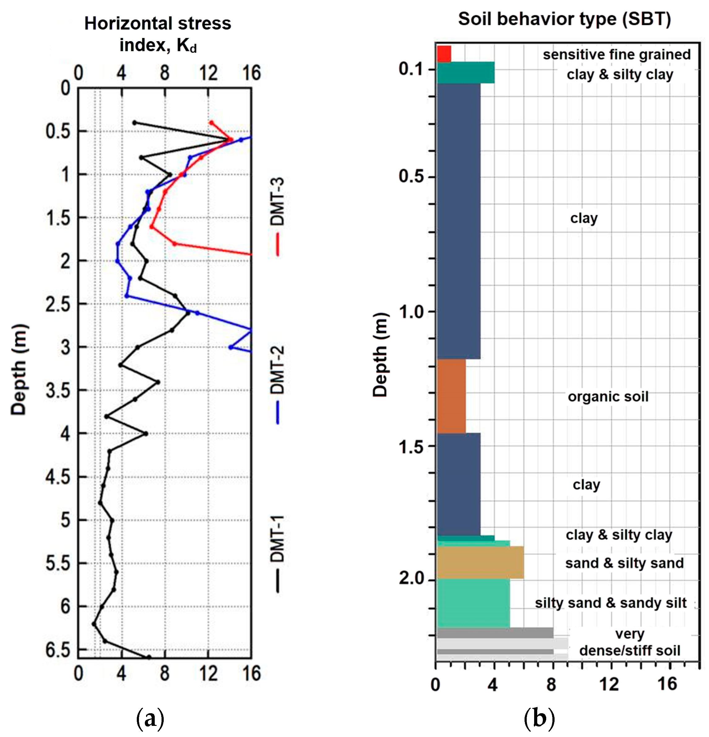
Three Cone Penetration Tests (CPTu) and three Dilatometer (DMT) probes were performed on the body of the Orehovčak landslide. Marchetti [
31] provided a comprehensive description of the Flat Dilatometer Test procedure, including the equipment used and the original correlations. The technique currently used involves employing a dilatometer to measure the in situ horizontal stress index (K
D) of soil [
32]. The field CPTu probing approach [
33] involves the hydraulic pressing of a steel cone penetrometer at a consistent speed to measure the total cone resistance (q
t), friction ratio (R
f), and pore pressure (u). The geotechnical parameters were estimated based on the data acquired from CPTu using the expression provided by Robertson [
34]. Hydraulic embossing equipment, Van Den Berg, model Hyson LW100 (
Figure 6c), was used for CPT and DMT in situ investigations.
2.5. Geotechnical Monitoring
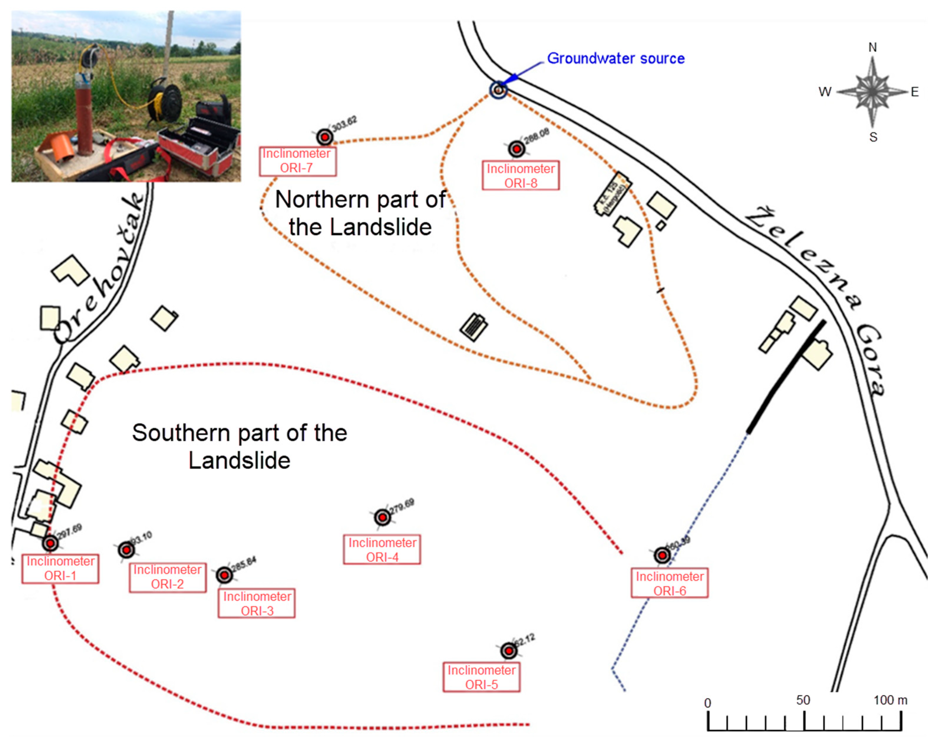
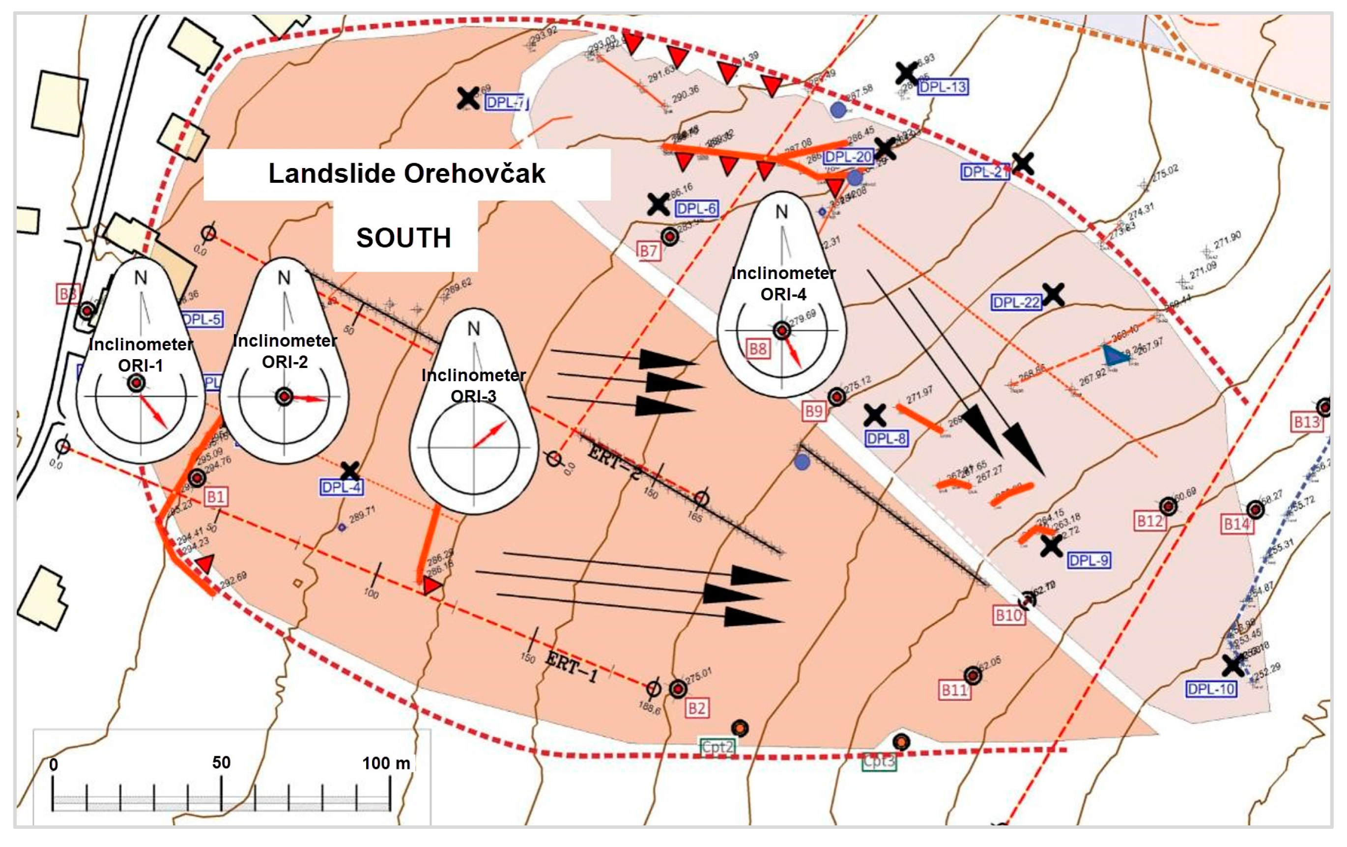
Eight of the eighteen drilled exploratory holes were equipped with inclinometer tubes for geotechnical monitoring (
Figure 7). ABS inclinometer tubes manufactured by SISGEO (Milano, Italy) were used, with an outer diameter of 71 mm and an inner diameter of 60 mm. The vertical inclinometer network was installed to observe horizontal movements and model control. The vertical inclinometer is the primary monitoring instrument used to measure the horizontal subsurface deformation in a borehole.
Measurements were performed using a digital inclinometer system using the biaxial digital MEMS measuring probe. The equipment for inclinometer observations consisted of the Archimede CDL300INCL registration unit, manufactured by SISGEO, and digital inclinometer measuring probe S242DV3000 (in the upper right corner of
Figure 7).
2.6. Analysis and Design
Slope stability analysis was performed according to a method proposed by Bishop [
35]. With this method, the analysis is carried out in terms of stresses instead of forces. The equilibrium moment is analyzed for each potentially unstable soil segment, and a cylindrical surface is assumed as the slip surface. Finally, the calculation boils down to determining the slip safety factor, which is defined as the ratio of the slip resistance moment and the moment of active forces around the potential field of rotation of the observed sliding body. Bishop’s method of slices was developed with a PC application SLIDE 6.0, Rocscience Inc. (Toronto, ON, Canada).
For the purpose of landslide remediation in Železna Gora, below the village Orehovčak, the conceptual project foresees the remediation of unstable space with deep dug drains and arrangement of surface drainage. A total of three drains have first been designed to drain the landslide body. Drains 1 and 3 are placed in the main directions of leachate and represent the backbone of drainage of the northern and southern parts of the landslide. Drain 2 is an extended branch of drain 1 for additional collection of leachate from the southern part of the landslide. The conceptual position of the planned drains before all research results were taken into account is shown in
Figure 8.
3. Results
3.1. Results of Geological Observing and Mapping
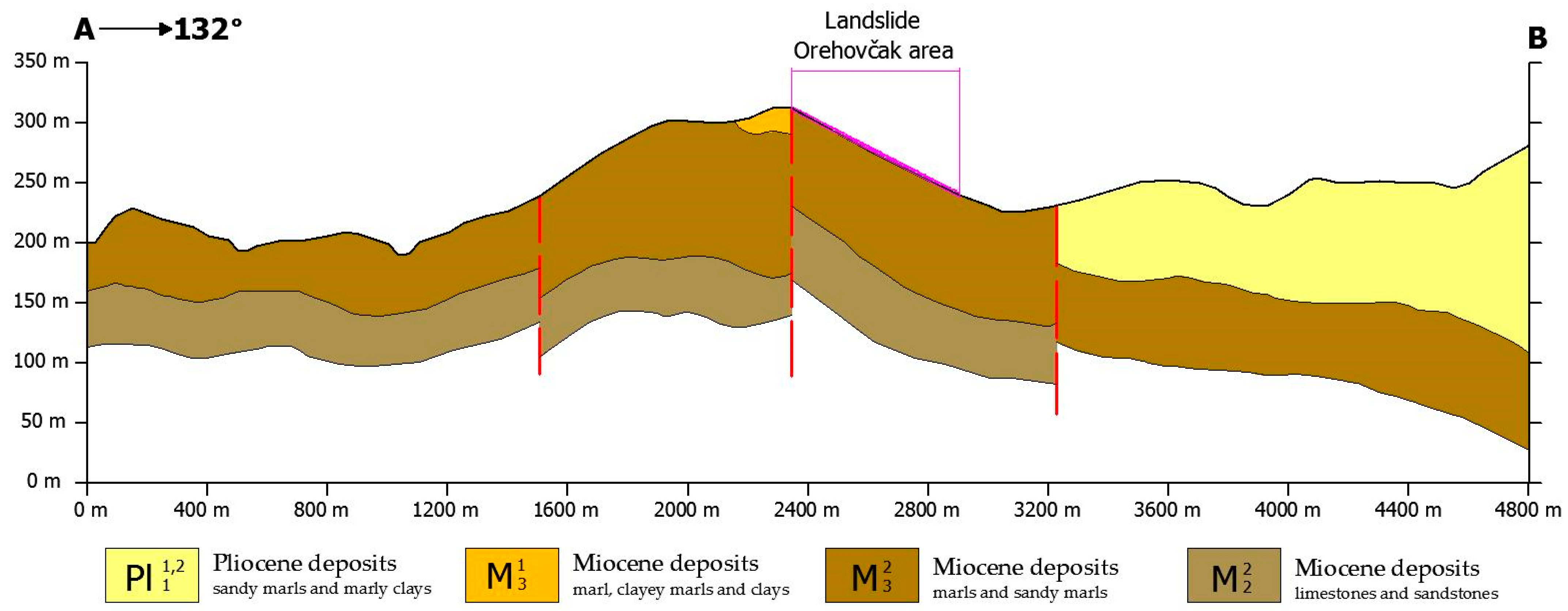
In the lower part of the lithological column are represented Miocene deposits (M22), predominantly limestones and sandstones. They are followed by thinly layered marls, sandy marls and sands with sandstone layers. Limestones have a high carbonate content (over 40%), and sands contain quartz grains, carbonate and feldspar. The thickness of these deposits is over 200 m, and they are located northwest of the landslide.
Geological materials marked M
31 in
Figure 2 and
Figure 9 are continuously deposited on carbonates and clasts. They are represented by thin-layered and plate-to-laminar marls of grey to yellow color. In addition to marl, clayey marls and clays are also present. Thicknesses of these deposits from 20 to 40 m were measured on open outcrops.
In the landslide zone, deposits M
32 in
Figure 2 and
Figure 9 are represented by materials such as marls and sandy marls. These greenish marls are followed by varieties of clastic sediments from clay to marl. The thickness of these layers varies from 100 to 200 m, and lithologically, they are very similar to Pliocene deposits Pl
11,2. These are thinly layered sandy marls and marly clays, grey to grey-green, and can be found southeast of the landslide.
3.2. Results of Geophysical Investigations
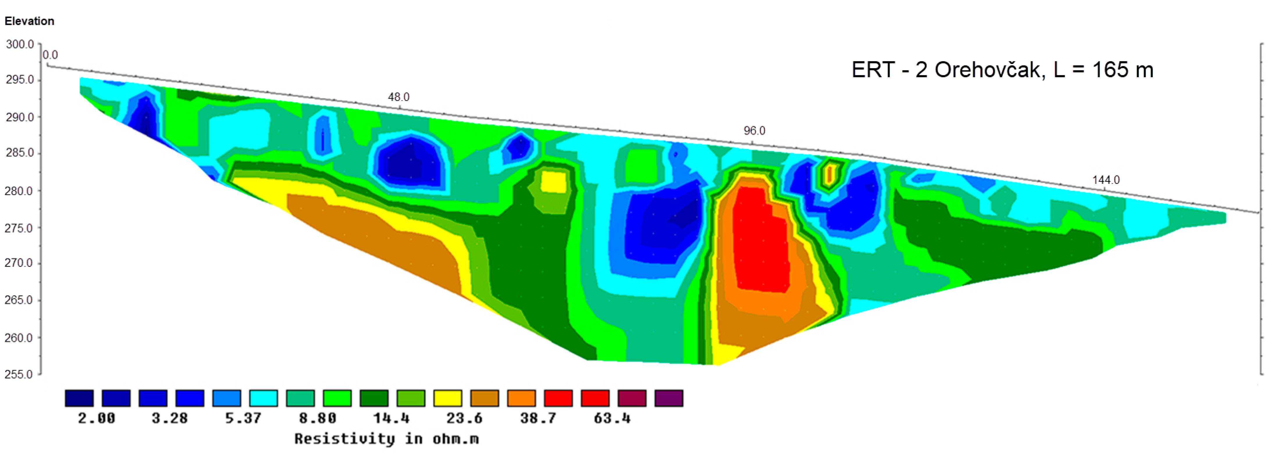
The interpreted results of the ERT are displayed as a graphical representation of the resistivity profile with depth. The profile is displayed in colors, where different colors, according to the legend, show different resistance zones. The soil types are distinguished according to the electrical tomography profile recorded at the location. The electrical tomography (ERT) profile identified that the sliding surface was formed within the clayey materials towards the subsoil of the marly clays. The results of ERT research in Orehovčak (
Figure 10) show that the sliding surface was formed within clay materials (<10 ohmmeters), according to the subsoil of marly clays and marls (10–25 ohmmeters).
From the measurements, a clear boundary between the clay roof and the base of marly clays and marl is not visible because these materials can have similar electrical resistance values. In addition, it is difficult to detect the line of the saturated zone because in clayey materials, a classic water face is not formed, but areas of greater and lesser water saturation appear. Therefore, it is impossible to distinguish the characteristics mentioned in detail within the electrical resistance profile.
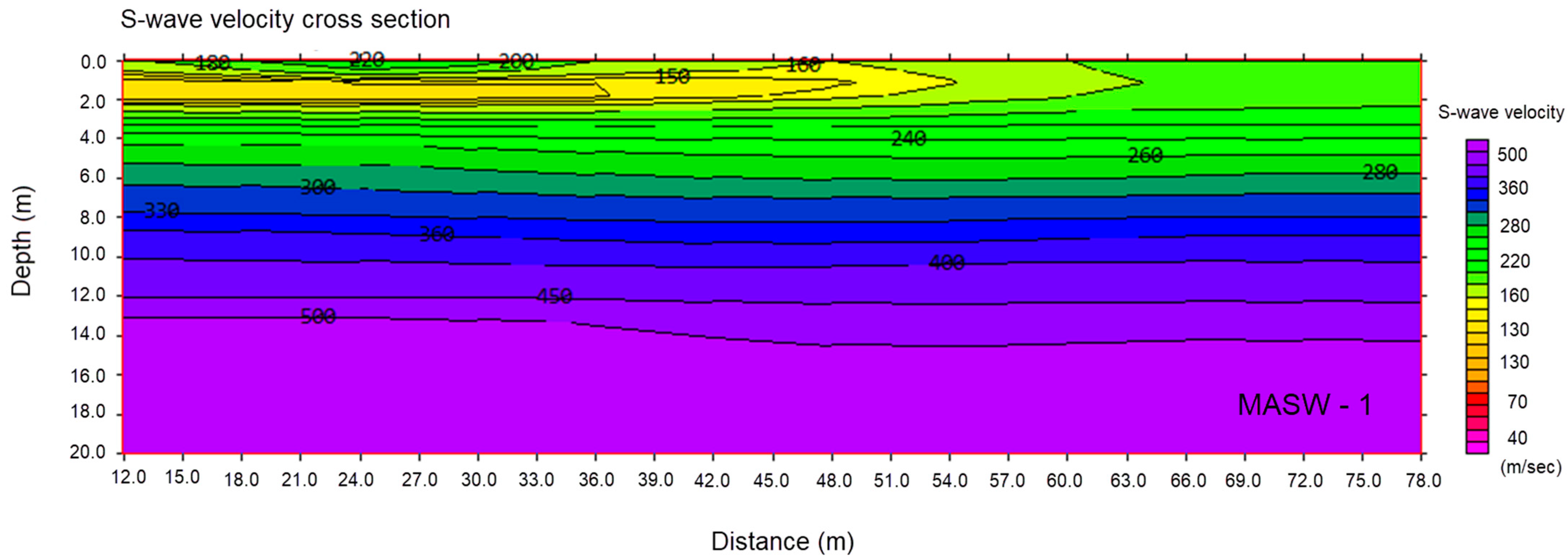
V
S information obtained by section MASW-1 is shown in
Figure 11. Lower velocities of S waves indicate clayey materials (<260 m/s), and higher velocities (260–500 m/s) indicate subsoil (marly clays and marls).
3.3. Results of Geotechnical Investigations
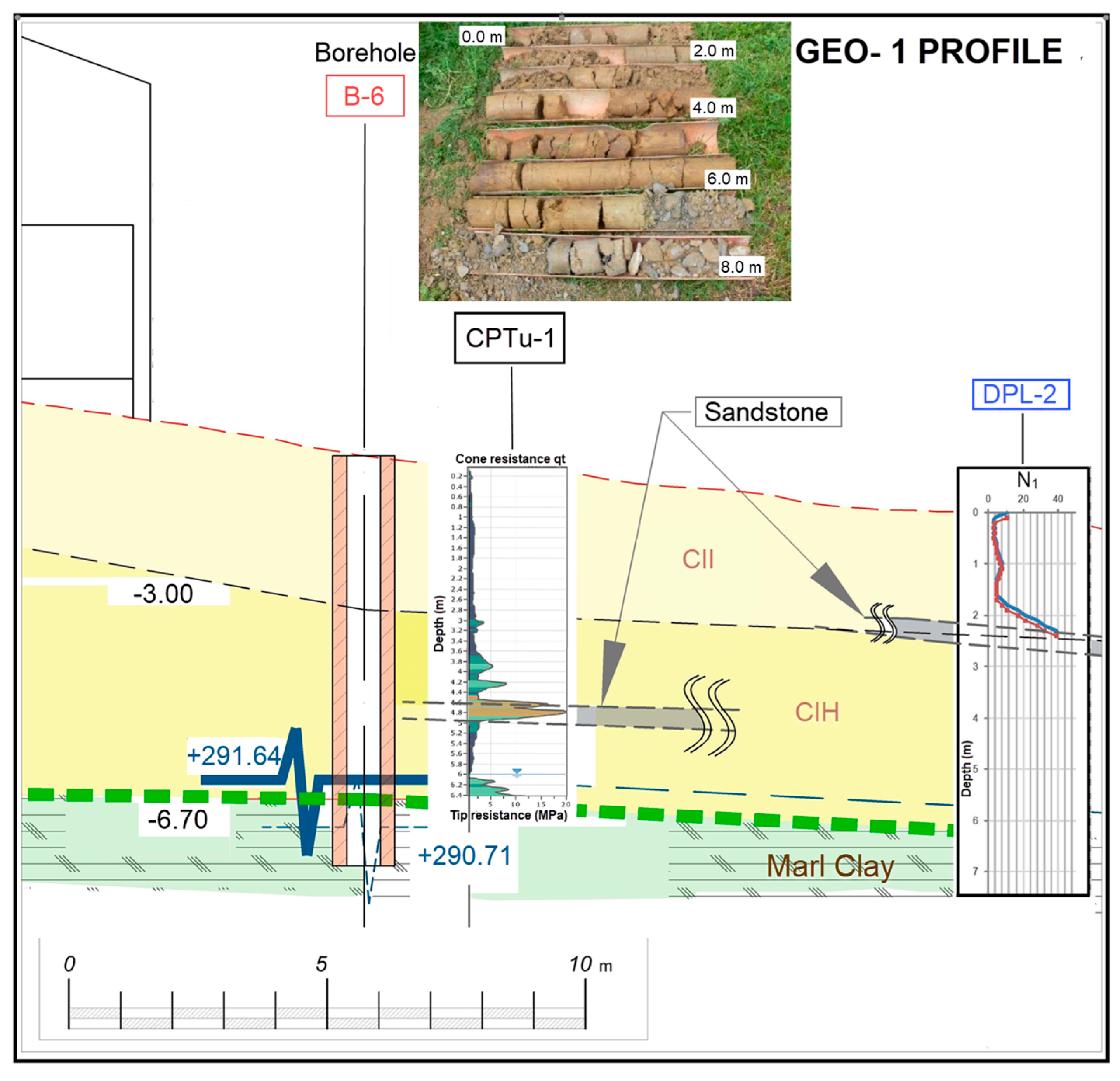
Based on boreholes’ static (CPTu and DMT) and dynamic (DPL) probing, it was determined that the base soil from the geotechnical classification aspect consists of clays of high plasticity (CIH), yield strength of w
L = 55–80%, yellow-brown color. Clays contain parts of grey clay. In boreholes B-3, B-5 and B-6, sandstone deposits up to 0.40 m thick were also identified.
Figure 12 shows the drilled core of borehole B-6. For the classification of CIH and CII materials (medium plasticity clay) shown in
Figure 12, the ESCS (European Soil Classification System) classification was used. [
36]. The sliding surface is located at the contact of the clay layer with the solid sublayer of the marl.
Figure 12 shows the example of the soil profile, named GEO-1 profile, with an overlay of well B-6, CPTu-1 and DPL-2 results. The results of static penetration tests (all three DMTs and CPTu-3) are shown in
Figure 13.
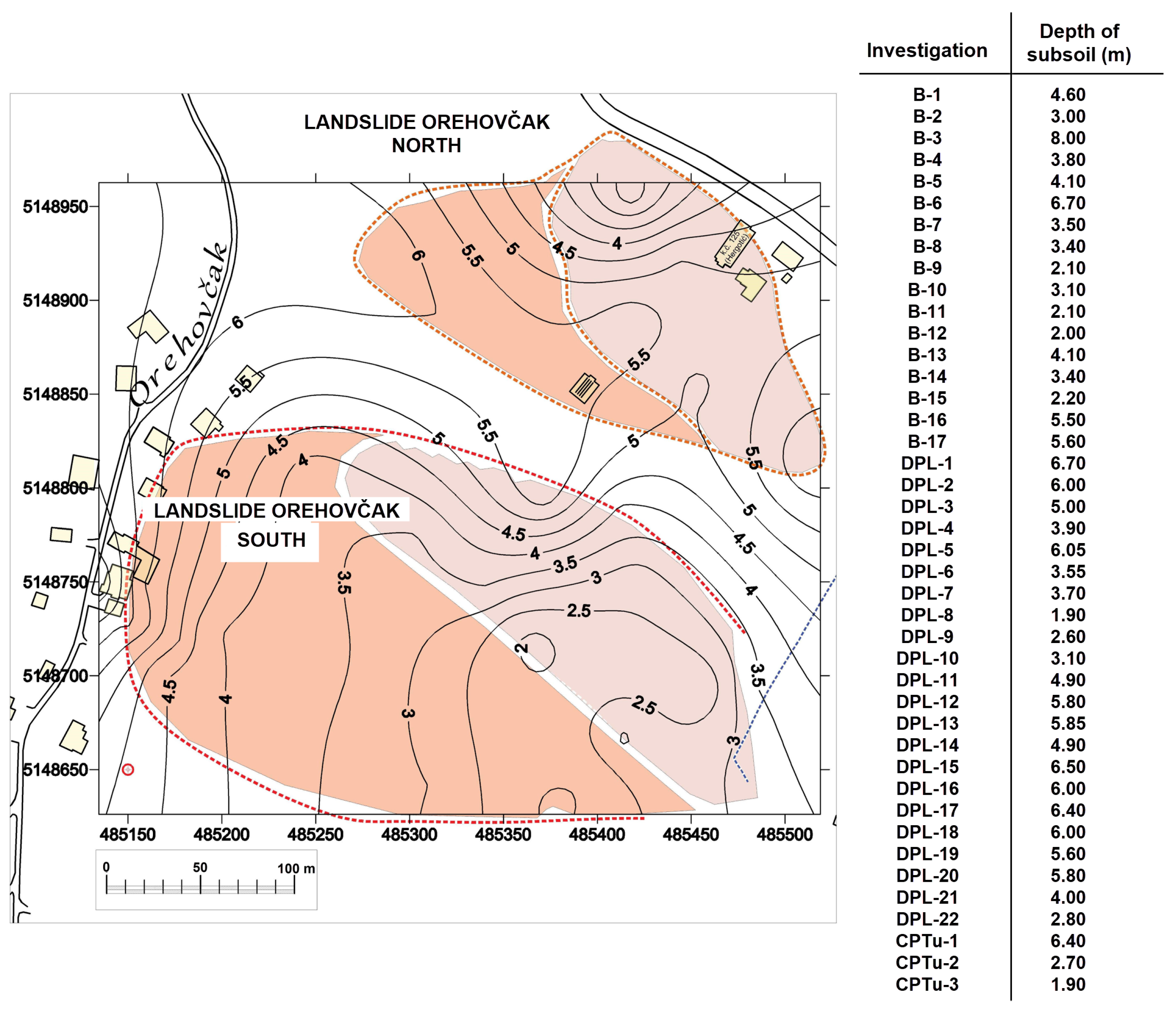
A large number of point data on the depth of the solid marl subsoil were obtained through investigative works, and for the purpose of systematizing the results, the subsoil (marly clays and marl) map shown in
Figure 14 was created.
The determined lithological composition and adopted parameters of the soil at the location in question based on the geophysical investigation results, identification of the drilled core from the boreholes, conducted static probing and laboratory tests are shown in
Table 1.
3.4. Results of Geotechnical Monitoring
Before establishing the inclinometer network in the middle of 2016, there was no topographic monitoring on the Orehovčak landslide that would have provided input data on trends in the slope velocity movement. The results of inclinometer observations show the measured deviations of individual points of the inclinometer tube from the zero line measured at the zero reading. The orientation of the displayed displacements is in accordance with the conventional representation (convention) in the polar diagram in the counterclockwise direction where the north direction is indicated by 90°. The results of the first reading on the four inclinometers installed in the first phase are shown in the situation in
Figure 15.
The displacement directions read on the inclinometers of the southern part of the landslide coincide with the predicted kinematics of the ground movement, and the displacement depths correspond to other results. The size of the displacement is up to 2 mm and was measured over a period of 20 days.
3.5. Hydrogeological Conditions in the Soil
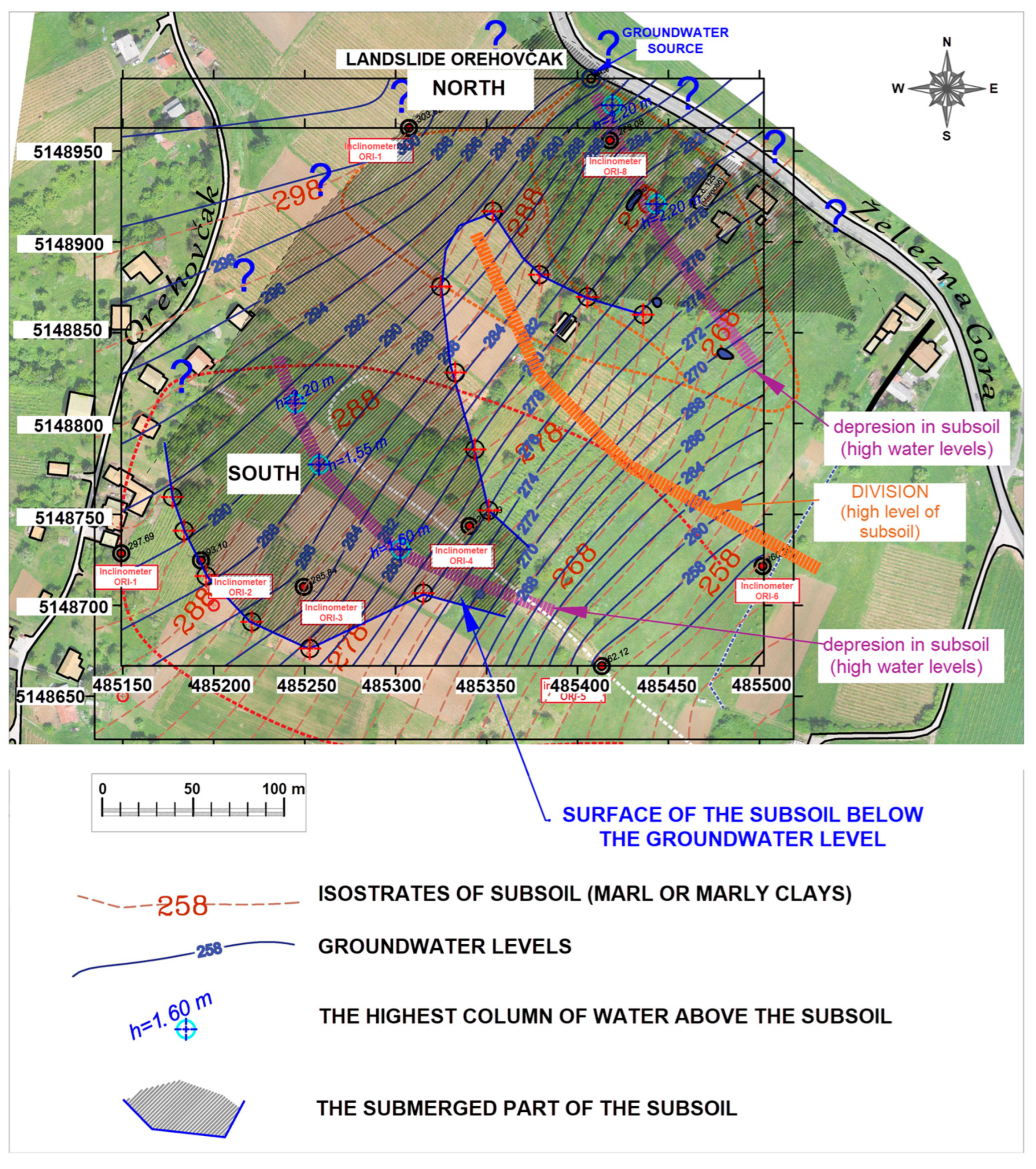
The main reason for the resulting displacements and the development of landslides is the accumulation, i.e., the high level of leachate in the zone of depression in the subsoil, and the “filling” of the slope is connected to the water source along the D227 State Road, where the water levels are always almost up to the surface of the terrain. The scheme of the above is shown in
Figure 16.
Sandy interlayers enable easier water percolation into deeper layers, which is the reason for the saturation of the up-layer sediments. Water is fed into these layers from higher parts of the terrain, and the pressures and fluctuations are related to the topography and, as a rule, are significant. By shifting the described layers, the filtered water does not have the possibility of quick evacuation from the slope, and it accumulates in the soil, increasing pore pressures. The potential of seepage water is the cause of the destabilization of the entire area, that is, the formation of landslides. The emergence of water in parts of the space is a confirmation of occasional high water levels and saturated conditions in the sliding body.
Figure 16 shows that the greatest fluctuations in groundwater levels are realized precisely in the area of the landslide. From the analysis, it is evident that the landslide consists of a sliding surface in contact with a solid subsoil. The landslide has a delapsive character, which is fast according to the speed of movement.
3.6. Analysis of Stability of Slope to Sliding
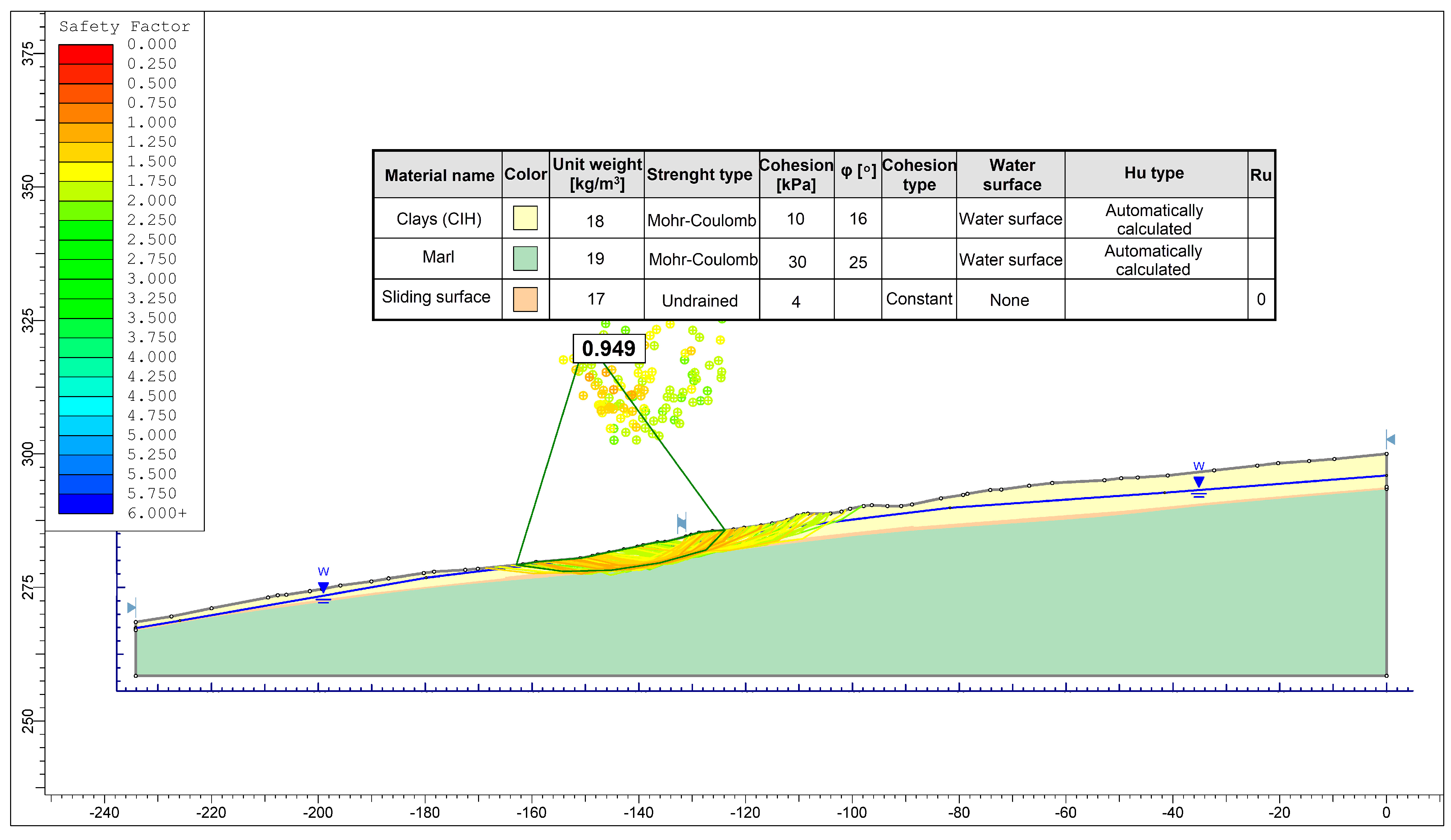
The slope stability analysis was performed for the most unfavorable case so that the shear strength on the sliding surface c
u = 18 kPa was taken into account. Other established conditions on the slope were also taken into account. The model with the used soil input parameters and loads is shown in
Figure 17.
The realized safety factor is slightly less than 1, which means that the slope is unstable for the selected model parameters. In this reverse analysis, no partial factors were applied, so the characteristic values equal the design values. The result Fs < 1 indicates that the destabilizing action of the forces is greater than the stabilizing action.
4. Discussion
As the hydrogeological conditions in the soil are the main cause of soil sliding in the location, i.e., water is the main trigger of instability, the area can be stabilized by lowering the leachate level. This is achieved by a system of deep drainages and the arrangement of surface drainages, which will effectively reduce the potential of groundwater if they are well-designed.
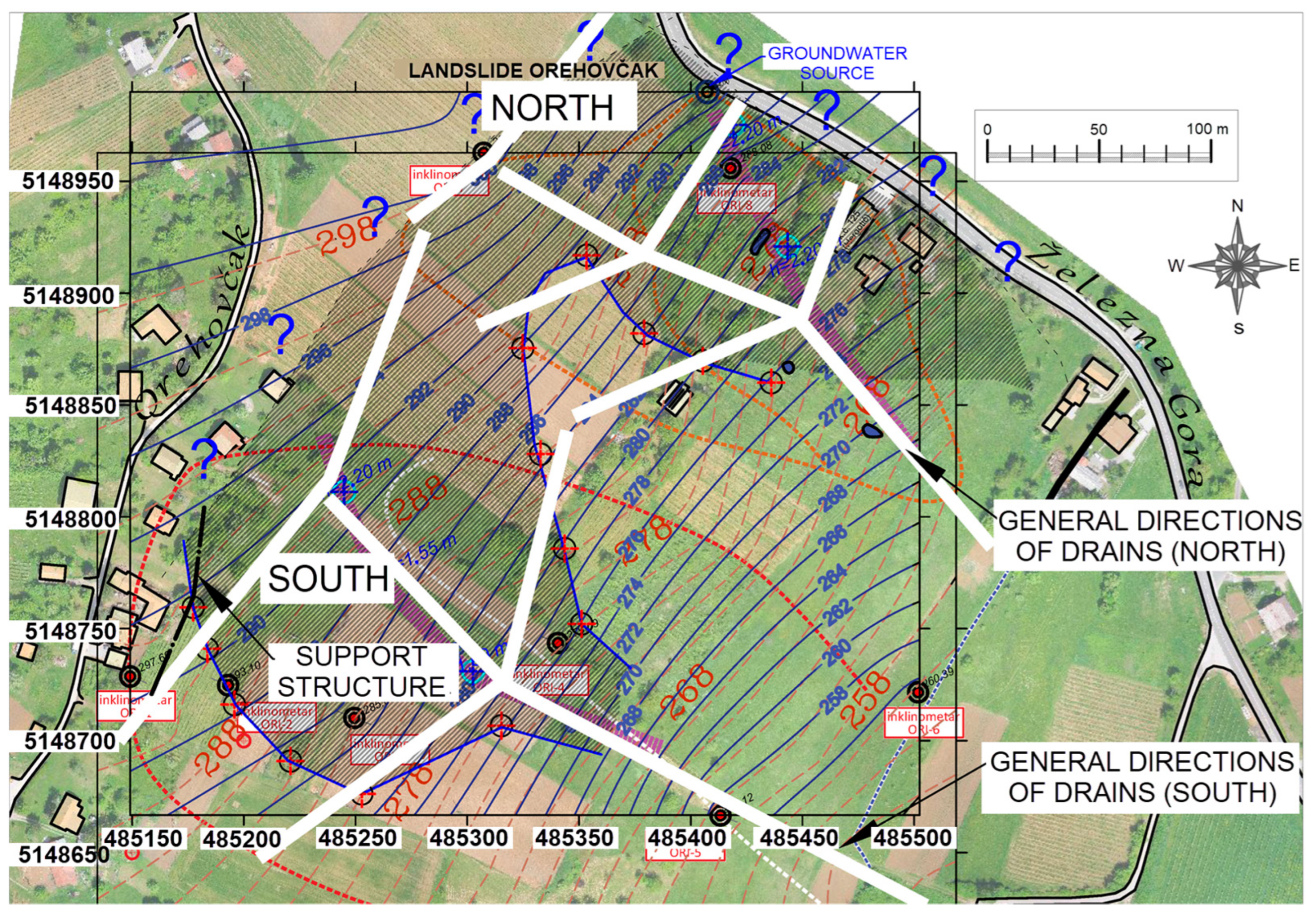
After conducting research and analyzing the obtained results, in combination with the hydrogeological conditions in the soil, the final position of the drains was determined. The general positions of the deep drains in the northern and southern parts of the landslide are shown in
Figure 18. In the same figure, it is also possible to see the position of the support structure to protect the damaged building in the village of Orehovčak (
Figure 3a). But, given that it is a minor intervention, it was not considered in detail in this paper.
Drainage of the body of the landslide was carried out with a total of three drains, of which drains 1 and 3 are placed in the main directions of seepage waters and represent the backbone of the drainage of the area of southern and northern parts of the landslide. Drain 2 is an extended branch of drain 1 for additional leachate collecting from the southern part of the landslide. The drain routes were established based on the results of recorded groundwater levels in the piezometer system created during the investigation phase (boreholes and inclinometers).
The basic design criterion was the depth of the drains, i.e., it was important that the deep drain be buried in a layer of impermeable marl so that it could accept all the leachate that infiltrates from the surface. The drainage system would certainly be able to accept all the water, given that the water permeability of the drainage material is enormously higher than the permeability of the surrounding clay material.
Before the excavation of the drains, rough levelling of the slope was carried out, followed by the excavation of preparatory plateaus on the routes of the deep drains. The total length of the excavated drains was 980 m. Excavation and installation of the filter material were performed in stages, according to the order of work and given technical conditions. Excavation of trenches for deep drains was carried out on two levels. The first part of the excavation was carried out as a wide excavation in sections up to 20 m long, up to the elevation of the deep (second) level. The lower level of excavation to the final depth was also carried out in sections up to 5 m long.
The excavated material, which was exchanged with the filter drainage stone material, was immediately taken to the landfill. Only smaller quantities needed for later installation in the surface part of the trench (clay backfill or plug) were left.
Drainage flexible PVC pipes with a diameter of 20 cm were laid in the channels excavated to the marly substrate (even deeper up to 20 cm). PVC D200/184 mm, TS360° (Pipelife DX) was used for the drainage pipes.
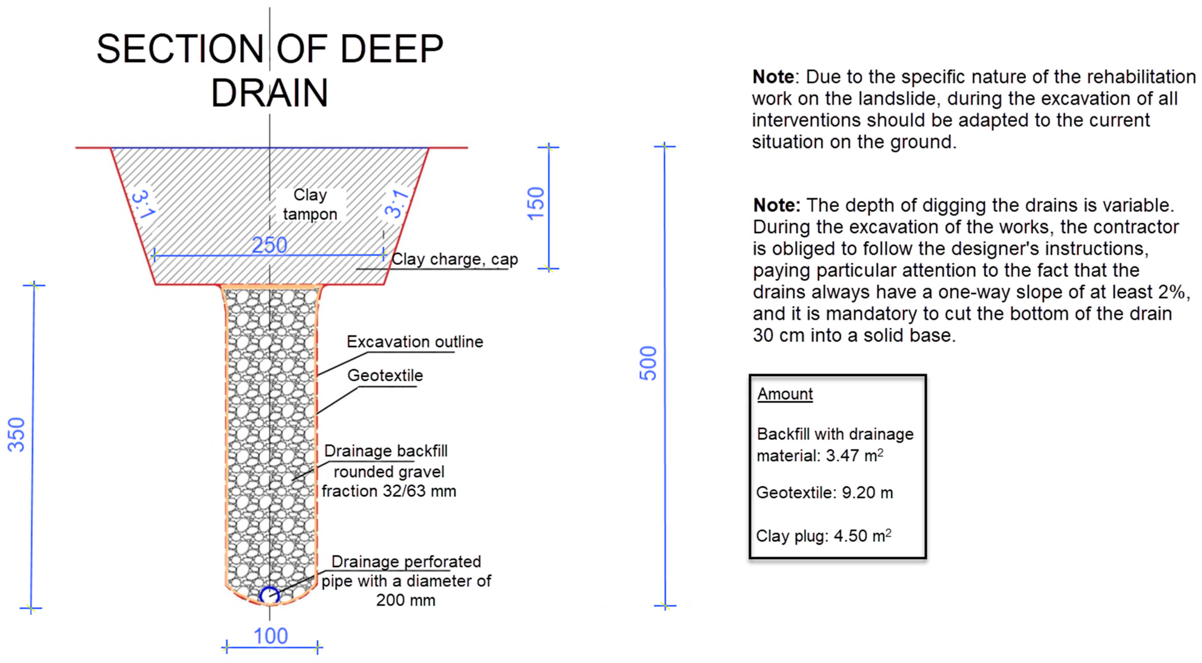
The filter material installation began after the drainage was completed in each section. Natural gravel or crushed stone with a 30–60 mm fraction was used as drainage material. The installation was carried out in layers with the compaction of each individual embedded layer. The drainage material was poured onto the drainage pipe, taking care not to damage the pipe. A geotextile was placed on top of the trench filled with filter stone. After that, a plug was made from a poorly permeable material (clay) that would prevent the uncontrolled entry of rainwater into the soil. The surface of the trench excavation for the drain is levelled after installation and compaction. The detail of the deep drain cross-section is shown in
Figure 19, and the drain construction at the location of the Orehovčak landslide is shown in
Figure 20.
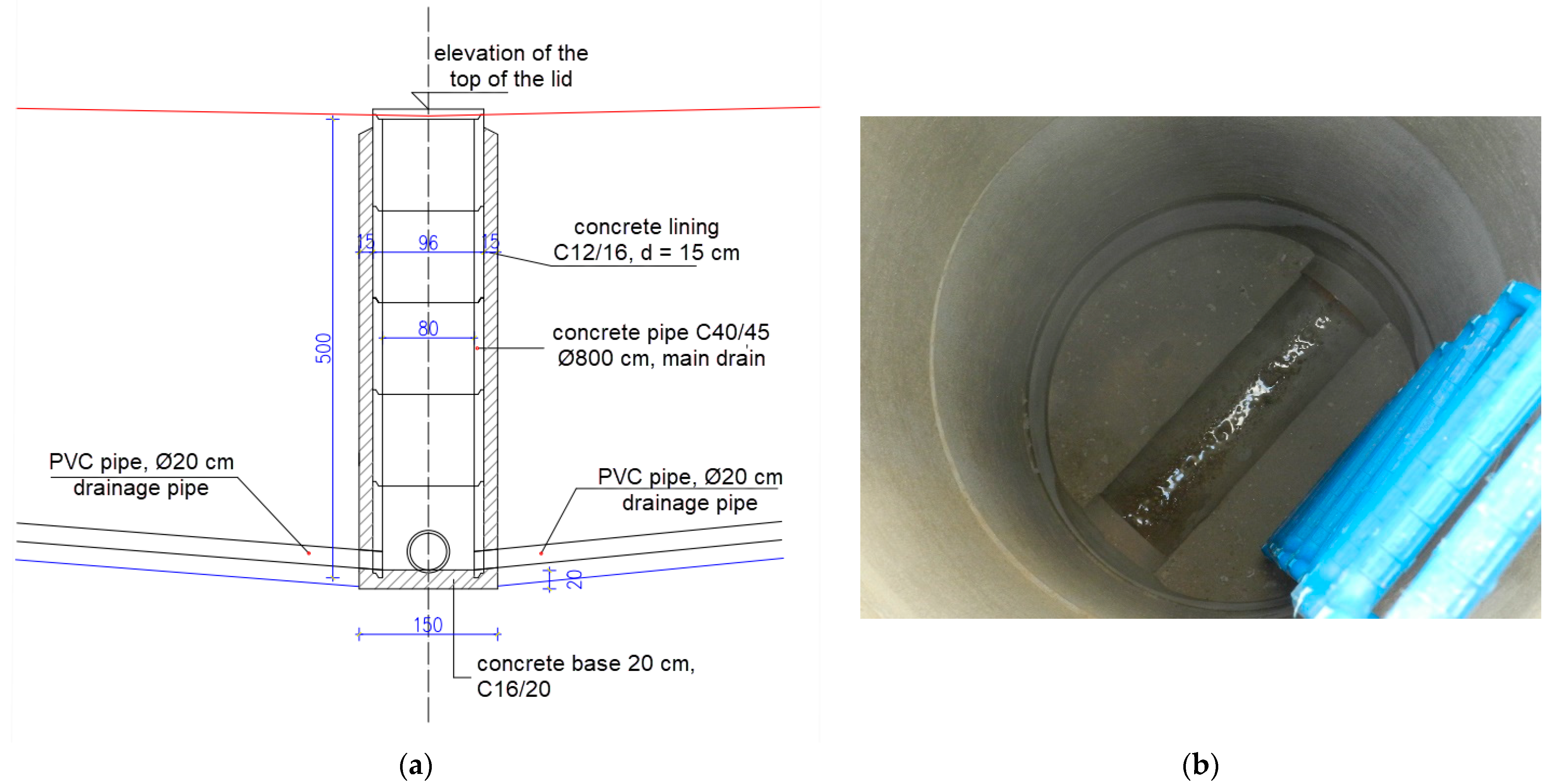
Inspection manholes (audit shafts) for drainage were built at the junctions and breaks of the drainage route (
Figure 21) for the purpose of maintenance and control of the functioning of the drainage. Inspection shafts are made of concrete sewer pipes with a diameter of 80 cm with a concrete cover. The windows were placed on a concrete base, and the concrete lining was installed along the entire height.
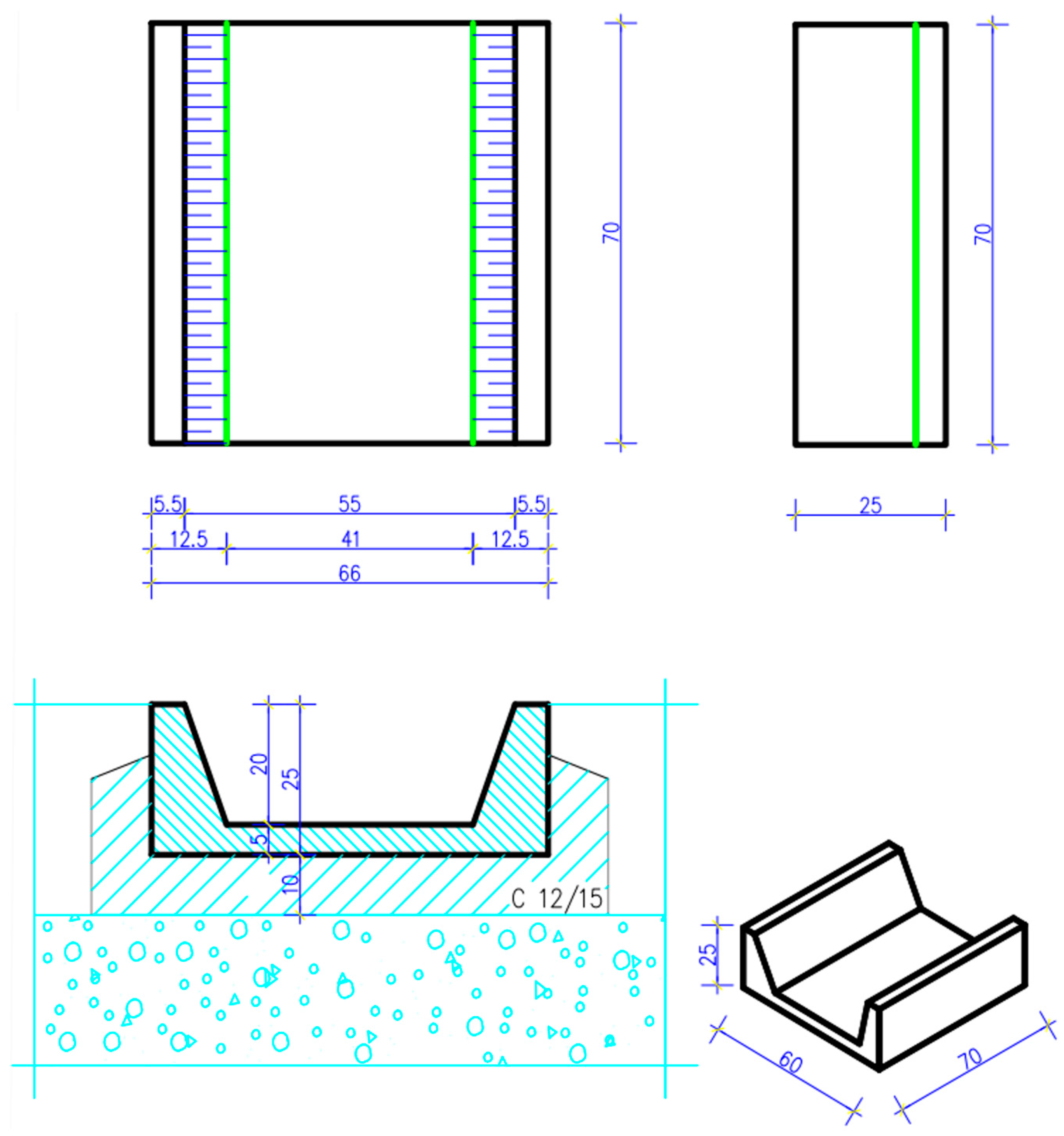
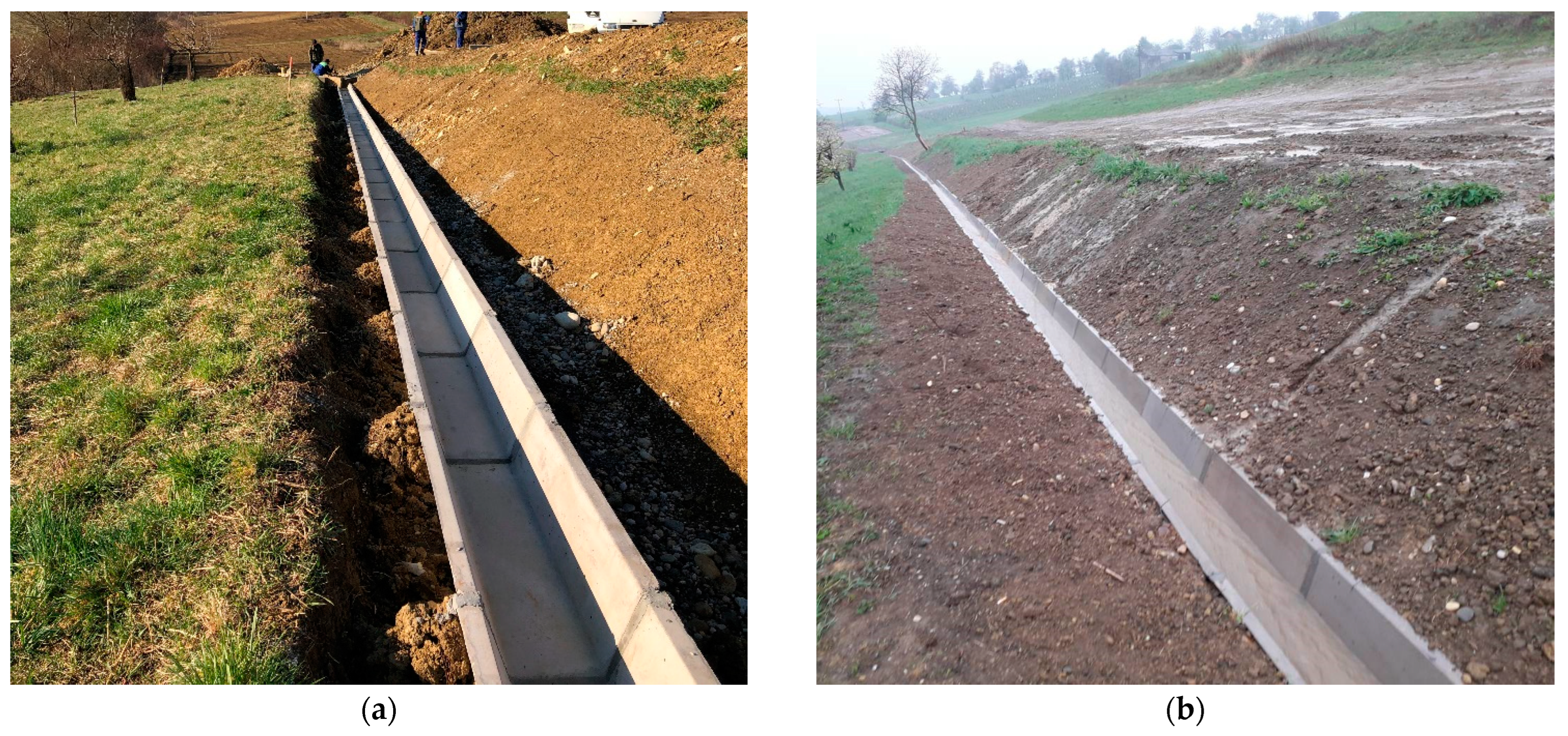
Other elements of the rehabilitation were related to the arrangement of storm surface drainage using concrete trapezoidal channels with dimensions of 66/25/70 cm (
Figure 22 and
Figure 23), anti-erosion protection of the slope of the main drainage channel with concrete grass grates, expansion of the existing drainage ditch and the construction of a tubular culvert under the access road. Existing rainwater drainage channels, which are made of concrete trapezoidal-conical channels, are used to drain water from the drainage system.
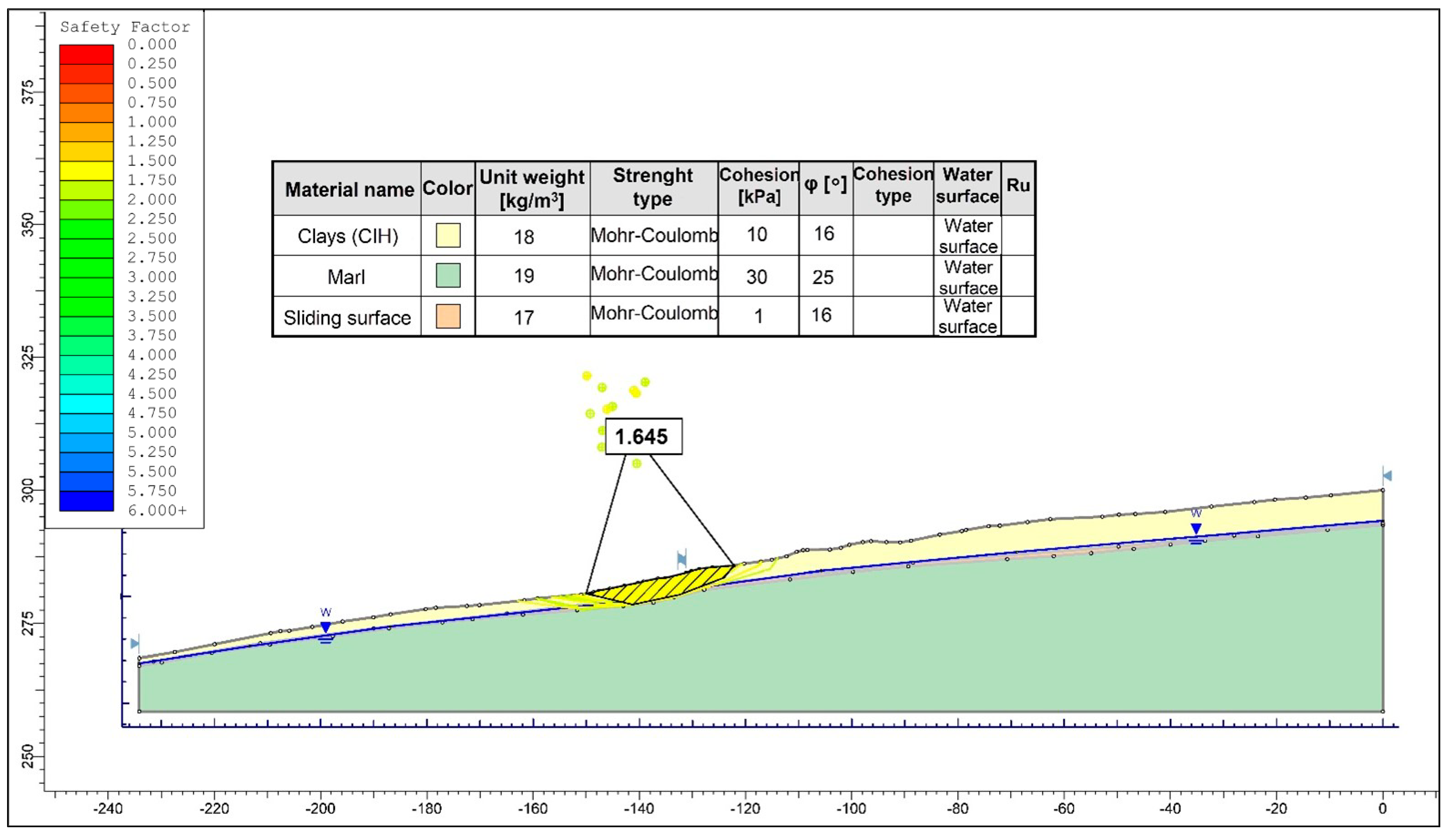
An analysis of slope stability was performed in all conditions on the slope that were achieved after the landslide rehabilitation by installing deep drains. The obtained safety factor was greater than 1.5 (
Figure 24), which proves that the stability of the landslide is achieved by the performance of the designed rehabilitation solution.
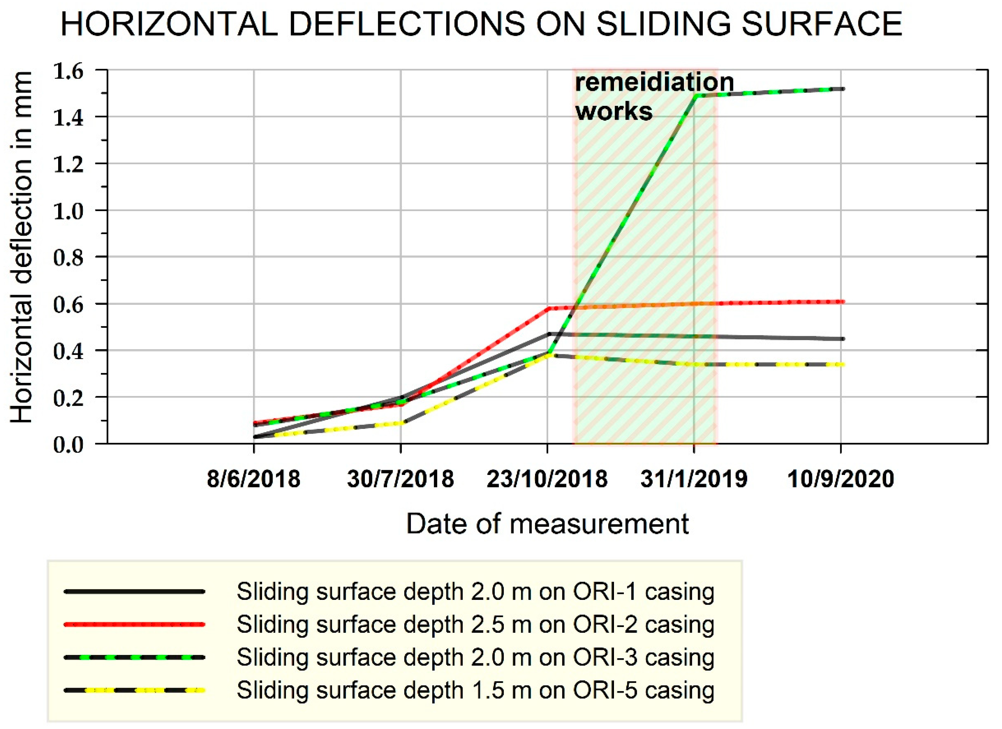
After the rehabilitation, observations were made again on the inclinometers. The measurement results show that there are no new movements after remediation and that the landslide has calmed down (
Figure 25).
5. Conclusions
The Orehovčak landslide is a classic example of a shallow landslide, the main trigger of which is rainwater infiltration into the clayey soil whose subsoil consists of marl at relatively shallow depths. Water, which infiltrates into the body of the slope after heavy rainfall, is generally the most common trigger of shallow landslides.
It is necessary to carry out detailed geological, geophysical and geotechnical investigations in order to determine the cause of the landslide, the nature of the fluctuation of underground water and solutions for the rehabilitation of the landslide. This is exactly what is shown by an example from this paper.
The scientific approach to this research is evident from the specific combination of applied research methods. Standard geotechnical soil investigation techniques (exploratory drilling, sampling and laboratory testing) and geophysical methods (especially MASW), combined with modern in situ geotechnical tests (CPT, DMT and DPL), have proven to be very successful in the detection of the slip surface. In addition, the investigation results are very useful when designing a remedial solution. The results of geotechnical observations also proved to be of high quality and useful. All of the above are advantages of the described research methodology, while the disadvantage is the cost of such a large research scale.
Vertical inclinometers were installed in the selected exploratory boreholes to monitor the evolution of landslides and determine horizontal displacements before and after rehabilitation.
The results of field investigations show that the surface soil on the slope in Orehovčak consists of highly plastic clay, and the sliding surface was created in contact with the solid subsoil of marl, the depth of which varies positionally. In the zone of the sliding surface, at the transition from clay to marl, an investigation has determined interlayers of sandy soil, which enable easier filtering of water. The water does not have the possibility of rapid evacuation from the slope and begins to accumulate in the soil, which increases pore pressures and reduces the shear strength of the soil. Such an analysis established that the high level of seepage water is the main cause of the displacements and development of the Orehovčak landslide.
Based on the interpretation of all obtained field and laboratory data, stabilization of the landslide was designed and carried out by installing and connecting three deep drains and arranging surface drainage using concrete channels. The control of the efficiency and durability of the drainage system is performed monthly by the municipal service of the local authorities by inspecting the audit manholes and measuring the level of underground water in piezometers.
To verify the correctness of the remedial solutions before the actual remedial works on the ground, numerical geotechnical modelling was again carried out, i.e., an analysis of slope stability under conditions of lowered groundwater level was carried out (Bishop’s method). Confirmation of landslide stabilization is the slope safety factor, whose calculated value after rehabilitation was Fs = 1.645 (in the found natural state, the slope safety factor was Fs = 0.949). The final confirmation of the landslide stabilization was obtained after the remedial works were carried out based on inclinometer measurements before and after the remediation. By comparing the readings of the inclinometer displacements at the depth of the sliding surface, it was proved that the slope had stopped sliding.
Finally, this paper presents the methodology of landslide research and the design of a rehabilitation solution. Stabilizing the slope with deep drains has proven to be very applicable and successful for a shallow landslide in northern Croatia, so there is certainly a very high potential for application to similar landslides around the world.
Given that it proved to be ineffective, the ERT geophysical method will no longer be used in future investigations of shallow landslides with a similar geological structure. Also, it is necessary to improve the organizational and financial approach to the investigation and implementation of rehabilitation works.
Author Contributions
Conceptualization, J.J. and K.G.; Methodology, J.J., K.G. and S.S.; Software, K.G. and A.B.; Validation, K.G., J.J., A.B. and S.S.; Formal analysis, K.G. and J.J.; investigation, J.J., K.G. and A.B.; resources, S.S.; writing—original draft preparation, J.J. and A.B.; writing—review and editing, K.G. and S.S.; visualization, K.G. and A.B.; supervision, J.J. and S.S.; project administration, J.J. All authors have read and agreed to the published version of the manuscript.
Funding
All described works on the Orehovčak landslide were financed by the municipality of Štrigova, Štrigova 87, Štrigova (40312), Croatia. Contract CLASS: 30003/18-01/2, REGULATORY NUMBER: 2109/18-18-10.
Data Availability Statement
The data presented in this study are openly available in article.
Acknowledgments
Institutional projects GFV-IP-2024, Faculty of Geotechnical Engineering, University of Zagreb, Hallerova aleja 7, Varaždin (42000), Croatia.
Conflicts of Interest
Kristijan Grabar was employed by the company SPP d.o.o., Koprivnička 47, 42000 Varaždin, Croatia. The remaining authors declare that the research was conducted in the absence of any commercial or financial relationships that could be construed as a potential conflict of interest.
Abbreviations
| CPTu | Cone Penetration Tests |
| MT | Dilatometer |
| PL | Dynamic Probe Light |
| ERT | Electrical Resistivity Tomography |
| ESCS | European Soil Classification System |
| MASW | Multichannel Analysis of Surface Waves |
| RS | Shallow Seismic Refraction Survey |
References
- Tabari, H. Climate change impact on flood and extreme precipitation increases with water availability. Sci. Rep. 2020, 10, 13768. [Google Scholar] [CrossRef] [PubMed]
- Waters, D.; Edgar Watt, W.; Marsalek, J.; Anderson, B.C. Adaptation of a Storm Drainage System to Accommodate Increased Rainfall Resulting from Climate Change. J. Environ. Plan. Manag. 2003, 46, 755–770. [Google Scholar] [CrossRef]
- Montrasio, L.; Valentino, R. A model for triggering mechanisms of shallow landslides. Nat. Hazards Earth Syst. Sci. 2008, 8, 1149–1159. [Google Scholar] [CrossRef]
- Caine, N. The rainfall intensity-duration control of shallow landslides and debris flows. Geogr. Ann. 1980, 62, 23–27. [Google Scholar]
- Giannecchini, R. Relationship between rainfall and shallow landslides in the southern Apuan Alps (Italy). Nat. Hazards Earth Syst. Sci. 2006, 6, 357–364. [Google Scholar] [CrossRef]
- Giannecchini, R.; Galanti, Y.; D’Amato Avanzi, G.; Barsanti, M. Probabilistic rainfall thresholds for triggering debris flows in a human-modified landscape. Geomorphology 2016, 257, 94–107. [Google Scholar] [CrossRef]
- Persichillo, M.G.; Bordoni, M.; Meisina, C.; Bartelletti, C.; Barsanti, M.; Giannecchini, R.; D’Amato Avanzi, G.; Galanti, Y.; Cevasco, A.; Brandolini, P.; et al. Shallow landslides susceptibility assessment in different environments. Geomat. Nat. Hazards Risk 2017, 8, 748–771. [Google Scholar] [CrossRef]
- Muntohar, A.S.; Liao, H.J. Rainfall infiltration: Infinite slope model for landslides triggering by rainstorm. Nat. Hazards 2010, 54, 967–984. [Google Scholar] [CrossRef]
- Brönnimann, C.S. Effect of Groundwateron Landslide Triggering. Ph.D. Thesis, Federal Polytechnic School of Lausanne, Lausanne, Switzerland, 2011. [Google Scholar]
- Take, W.A.; Beddoe, R.A.; Davoodi-Bilesavar, R.; Phillips, R. Effect of antecedent groundwater conditions on the triggering of static liquefaction landslides. Landslides 2014, 12, 469–479. [Google Scholar] [CrossRef]
- Reza Beyabanaki, S.A.; Bagtzoglou, A.C.; Anagnostou, E.N. Effects of groundwater table position, soil strength properties and rainfall on instability of earthquake-triggered landslides. Environ. Earth Sci. 2016, 75, 358. [Google Scholar] [CrossRef]
- Strelec, S.; Mesec, J.; Grabar, K.; Jug, J. Implementation of in-situ and geophysical investigation methods (ERT & MASW) with the purpose to determine 2D profile of landslide. Acta Montan. Slovaca 2017, 22, 345–358. [Google Scholar]
- Mihalić Arbanas, S.; Arbanas, Ž.; Krkač, M.; Bernat Gazibara, S.; Vivoda Prodan, M.; Đomlija, P.; Jagodnik, V.; Dugonjić Jovančević, S.; Sečanj, M.; Peranić, J. Landslide riski reduction in Croatia: Scientific research in the framework of the WCoE 2014–2017, IPL-173, IPL-184, ICL ABN. In Advancing Culture of Living with Landslides, Proceedings of the 4th World Landslide Forum, Ljubljana, Slovenija, 29 May–2 June 2017; Sassa, K., Mikoš, M., Yin, Y., Eds.; Springer: Cham, Switzerland, 2017. [Google Scholar] [CrossRef]
- Jordanova, G.; Gariano, S.L.; Melillo, M.; Peruccacci, S.; Brunetti, M.T.; Jemec Auflič, M. Determination of Empirical Rainfall Thresholds for Shallow Landslides in Slovenia Using an Automatic Tool. Water 2020, 12, 1449. [Google Scholar] [CrossRef]
- Salciarini, D.; Godt, J.W.; Savage, W.Z.; Conversini, P.; Baum, R.L.; Michael, J.A. Modeling regional initiation of rainfall-induced shallow landslides in the eastern Umbria Region of central Italy. Landslides 2006, 3, 181–194. [Google Scholar] [CrossRef]
- Tofani, V.; Bicocchi, G.; Rossi, G.; Segoni, S.; D’Ambrosio, M.; Casagli, N.; Catani, F. Soil characterization for shallow landslides modeling: A case study in the Northern Apennines (Central Italy). Landslides 2017, 14, 755–770. [Google Scholar] [CrossRef]
- Corsini, A.; Borgatti, L. Mountain Landslides: Monitoring, Modeling, and Mitigation. Geosciences 2019, 9, 365. [Google Scholar] [CrossRef]
- Fusco, F.; De Vita, P.; Mirus, B.B.; Baum, R.L.; Allocca, V.; Tufano, R.; Di Clemente, E.; Calcaterra, D. Physically Based Estimation of Rainfall Thresholds Triggering Shallow Landslides in Volcanic Slopes of Southern Italy. Water 2019, 11, 1915. [Google Scholar] [CrossRef]
- Remondo, J.; González-Díez, A.; De Terán, J.R.D.; Cendrero, A. Landslide Susceptibility Models Utilising Spatial Data Analysis Techniques. A Case Study from the Lower Deba Valley, Guipuzcoa (Spain). Nat. Hazards 2003, 30, 267–279. [Google Scholar] [CrossRef]
- Grabar, K.; Strelec, S.; Jug, J.; Stanko, D. Workflow for the geotechnical landslide model—Case study from north Croatia. In Proceedings of the 19th International Multidisciplinary Scientific Geo Conference SGEM, Albena, Bulgaria, 30 June–6 July 2019. [Google Scholar] [CrossRef]
- Croatia Map 360°. Map of Croatia with Cities. Available online: https://croatiamap360.com/croatia-cities-map (accessed on 15 February 2024).
- Del Greco, O.; Oggeri, C. Reinforcement design and control of rock slopes above tunnel portals in northern Italy. Int. J. Rock Mech. Min. Sci. 2004, 41, 515. [Google Scholar] [CrossRef]
- Mioč, P.; Marković, S. Basic Geological Map of Croatia and Slovenia M 1:100000, Sheet L 33-57 Čakovec; Institute for Geology, Geotechnics and Geophysics: Ljubljana, Slovenia; Institute for Geological Surveys: Zagreb, Croatia, 1998. [Google Scholar]
- Mioč, P.; Marković, S. Interpreter of the Basic Geological Map of Croatia and Slovenia M 1:100000, Sheet L 33-57 Čakovec, 1st ed.; Institute for Geology, Geotechnics and geophysics: Ljubljana, Slovenia; Institute for Geological Surveys: Zagreb, Croatia, 1998; pp. 20–27. [Google Scholar]
- Loke, M.H.; Chambers, J.E.; Kuras, O. Instrumentation, electrical resistivity. In Solid Earth Geophysics Encyclopedia, 2nd ed.; Gupta, H., Ed.; Springer: Berlin, Germany, 2011; pp. 599–604. [Google Scholar]
- Loke, M.H. Rapid 2D resistivity & IP inversion using the least-squares method. In RES2dINV Program Manual, 4th ed.; Geotomo Software: Gelugor, Malaysia, 2019; pp. 74–82. [Google Scholar]
- Jug, J.; Stanko, D.; Grabar, K.; Hrženjak, P. New approach in the application of seismic methods for assessing surface excavatability of sedimentary rocks. Bull. Eng. Geol. Environ. 2020, 79, 3797–3813. [Google Scholar] [CrossRef]
- Park, C.B.; Miller, R.D.; Xia, J. Multichannel analysis of surface waves. Geophysics 1999, 64, 800–808. [Google Scholar] [CrossRef]
- Foti, S.; Parolai, S.; Albarello, D.; Picozzi, M. Application of Surface-Wave Methods for Seismic Site Characterization. Surv. Geophys. 2011, 32, 777–825. [Google Scholar] [CrossRef]
- Cope, M. Dynamic probe theory revisited—Effective interpretation of dynamic test results. In Proceedings of the CETANZ Conference, Auckland, New Zeland, 23–24 September 2010. [Google Scholar]
- Marchetti, S. In situ tests by flat dilatometer. J. Geotech. Eng. Div. 1980, 106, 299–321. [Google Scholar] [CrossRef]
- Totani, G.; Calabrese, M.; Marchetti, S.; Monaco, P. Use of in situ flat dilatometer (DMT) for ground characterization in the stability analysis of slopes. In Proceedings of the 14th International Conference on Soil Mechanics and Foundation Engineering, Hamburg, Germany, 6–12 September 1997. [Google Scholar]
- Lunne, T.; Robertson, P.K.; Powell, J.J.M. Cone Penetration Testing in Geotechnical Practice, 1st ed.; Spon Press: London, UK; Taylor and Francis Group: New York, NY, USA, 1997. [Google Scholar]
- Robertson, P.K.; Cabal, K.L. Guide to Cone Penetration Testing for Geotechnical Engineering, 4th ed.; Gregg Drilling & Testing, Inc.: Benicia, CA, USA, 2012. [Google Scholar]
- Bishop, A.W. The use of the Slip Circle in the Stability Analysis of Slopes. Geotechnique 1955, 5, 7–17. [Google Scholar] [CrossRef]
- Kovačević, M.H.; Jurić-Kačunić, D.; Lubrić, L.; Ivoš, G. Engineering soil classification EN ISO 14688-2:2018. Građevinar 2018, 70, 873–879. [Google Scholar] [CrossRef]
Figure 1.
Location of landslide Orehovčak in northern Croatia (adapted according to [
21]).
Figure 1.
Location of landslide Orehovčak in northern Croatia (adapted according to [
21]).
Figure 2.
Geological map for the wider area of Orehovčak (adapted according to [
20]).
Figure 2.
Geological map for the wider area of Orehovčak (adapted according to [
20]).
Figure 3.
Visible occurrences on the landslide: (a) building damage that resulted in the emigration of residents, (b) muddy mass that made agricultural production impossible, (c) tilted trees that had to be cut down.
Figure 3.
Visible occurrences on the landslide: (a) building damage that resulted in the emigration of residents, (b) muddy mass that made agricultural production impossible, (c) tilted trees that had to be cut down.
Figure 4.
Locations of field investigations at the landslide Orehovčak, adapted according to [
20].
Figure 4.
Locations of field investigations at the landslide Orehovčak, adapted according to [
20].
Figure 5.
Geophysical investigation equipment: (a) ARES for ERT; (b) GEODE for SRS and MASW.
Figure 5.
Geophysical investigation equipment: (a) ARES for ERT; (b) GEODE for SRS and MASW.
Figure 6.
Geotechnical in situ investigation equipment: (a) boring machine Comacchio Geo 205; (b) DPL Nordmeyer Geotool PR 30; (c) Hydraulic embossing equipment Hyson LW100.
Figure 6.
Geotechnical in situ investigation equipment: (a) boring machine Comacchio Geo 205; (b) DPL Nordmeyer Geotool PR 30; (c) Hydraulic embossing equipment Hyson LW100.
Figure 7.
Locations of eight vertical inclinometers at the Landslide Orehovčak, together with the display of the monitoring equipment in the upper right corner.
Figure 7.
Locations of eight vertical inclinometers at the Landslide Orehovčak, together with the display of the monitoring equipment in the upper right corner.
Figure 8.
The conceptual position of the planned drains.
Figure 8.
The conceptual position of the planned drains.
Figure 9.
Geological profile that crosses the area of the Orehovčak landslide.
Figure 9.
Geological profile that crosses the area of the Orehovčak landslide.
Figure 10.
Two-dimensional model of soil electrical resistivity at the section ERT-2.
Figure 10.
Two-dimensional model of soil electrical resistivity at the section ERT-2.
Figure 11.
Two-dimensional model of S-waves velocities at the section MASW-1.
Figure 11.
Two-dimensional model of S-waves velocities at the section MASW-1.
Figure 12.
Landslide soil model on GEO-1 profile on location Orehovčak.
Figure 12.
Landslide soil model on GEO-1 profile on location Orehovčak.
Figure 13.
The results of static penetration tests: (a) DMT; (b) CPTu-3.
Figure 13.
The results of static penetration tests: (a) DMT; (b) CPTu-3.
Figure 14.
Isobaths of solid subsoil (marl and marl clays) measured in meters.
Figure 14.
Isobaths of solid subsoil (marl and marl clays) measured in meters.
Figure 15.
Movement directions read on inclinometers of ORI-1 to ORI-4.
Figure 15.
Movement directions read on inclinometers of ORI-1 to ORI-4.
Figure 16.
Hydrogeological map—state of groundwater levels.
Figure 16.
Hydrogeological map—state of groundwater levels.
Figure 17.
Characteristic profile and soil model used in the calculation of safety factors before rehabilitation (back analysis).
Figure 17.
Characteristic profile and soil model used in the calculation of safety factors before rehabilitation (back analysis).
Figure 18.
Drainage directions of the slope and position of the supporting structure.
Figure 18.
Drainage directions of the slope and position of the supporting structure.
Figure 19.
Characteristic cross-section of the deep drain.
Figure 19.
Characteristic cross-section of the deep drain.
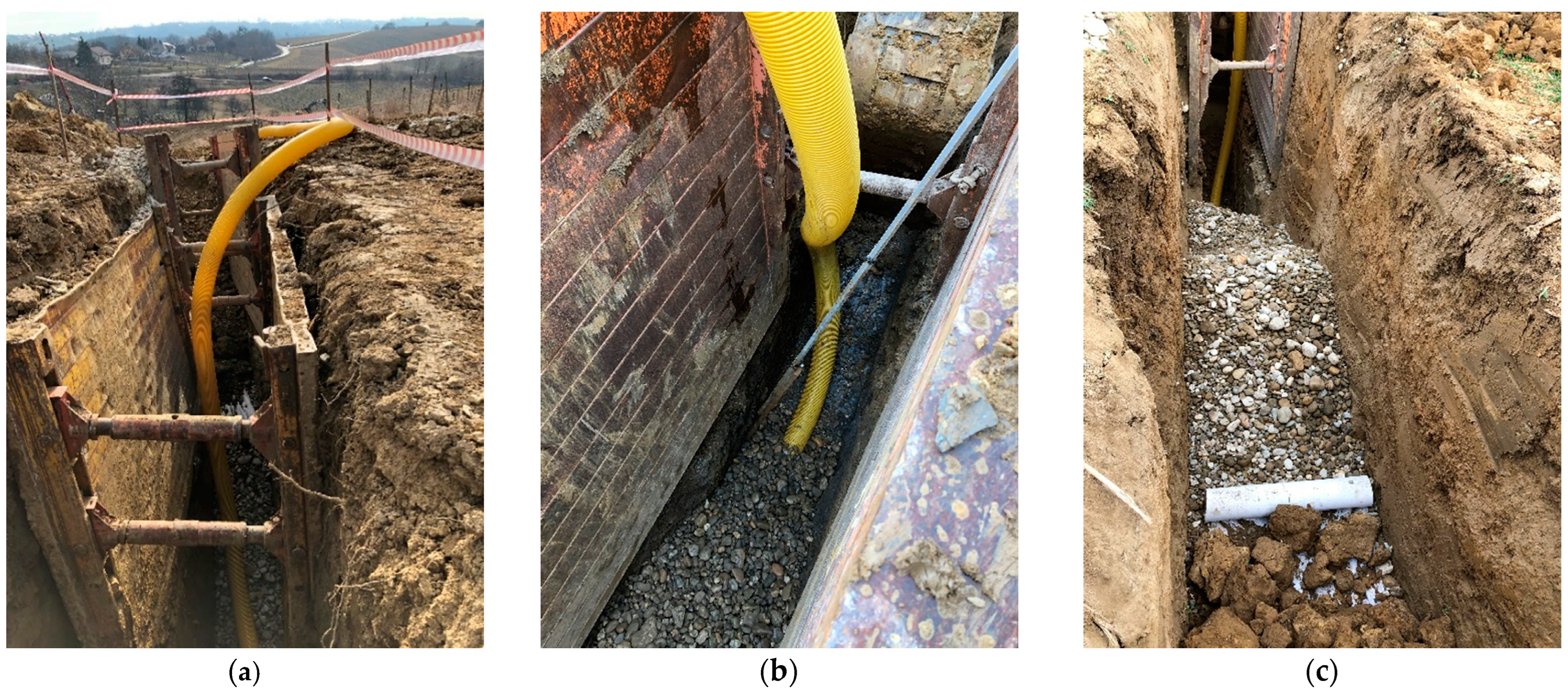
Figure 20.
Building of the deep drain on the Orehovčak landslide: (a) excavation protection; (b) installation of perforated drainage pipe; (c) backfilling drain with drainage material.
Figure 20.
Building of the deep drain on the Orehovčak landslide: (a) excavation protection; (b) installation of perforated drainage pipe; (c) backfilling drain with drainage material.
Figure 21.
Audit shafts: (a) characteristic section; (b) view of the drain through the drainage audit shaft.
Figure 21.
Audit shafts: (a) characteristic section; (b) view of the drain through the drainage audit shaft.
Figure 22.
A characteristic section of a concrete trapezoidal channel. Dimensions in the figure are in centimeters (cm).
Figure 22.
A characteristic section of a concrete trapezoidal channel. Dimensions in the figure are in centimeters (cm).
Figure 23.
Concrete trapezoidal channel: (a) during the building; (b) completed.
Figure 23.
Concrete trapezoidal channel: (a) during the building; (b) completed.
Figure 24.
Characteristic profile and soil model used in the calculation of safety factors after the rehabilitation of the landslide.
Figure 24.
Characteristic profile and soil model used in the calculation of safety factors after the rehabilitation of the landslide.
Figure 25.
Observation results of selected inclinometers where the most significant horizontal deflections were recorded.
Figure 25.
Observation results of selected inclinometers where the most significant horizontal deflections were recorded.
Table 1.
The determined lithology and adopted parameters of the soil at the location.
Table 1.
The determined lithology and adopted parameters of the soil at the location.
| | Ground Cover | Subsoil | Sliding Surface |
|---|
| Material | High plasticity clays (ClH) | Marly clays and marl | High plasticity clays (CIH) |
| Depth (m) | 0.0–max. 6.0 | min. 1.90 m >> | Different depths, depending on the research location |
| Parameters | qu = 50–250 kN/m2
cu = 25–100 kN/m2
γ = 17.0–18.0 kN/m3
c = 12–29 kN/m2
φ = 16°–25° | cu > 80 kN/m2
γ = 19.0 kN/m3
c > 30 kN/m2
φ = 25°
VP = 2200 m/s
Vs = 400 m/s | Minimum measured
parameters:
cu = 18 kN/m2
γ = 17 kN/m3 |
| Disclaimer/Publisher’s Note: The statements, opinions and data contained in all publications are solely those of the individual author(s) and contributor(s) and not of MDPI and/or the editor(s). MDPI and/or the editor(s) disclaim responsibility for any injury to people or property resulting from any ideas, methods, instructions or products referred to in the content. |
© 2024 by the authors. Licensee MDPI, Basel, Switzerland. This article is an open access article distributed under the terms and conditions of the Creative Commons Attribution (CC BY) license (https://creativecommons.org/licenses/by/4.0/).


