1. Introduction
In powder handling processes, electrostatic charging of powders becomes extremely important when powders are getting smaller and heated (because of the rise in temperature) due to the fast movement of particles [
1]. For instance, in pneumatic conveying, charged particles and the accumulated charge on particles potentially lead to agglomeration of powders, resulting in the risk of fire and explosions, or hazards of a coating surface on equipment [
2]. Particulate solids can be electrically charged when the solids are in contact with other particles or equipment surfaces, where the solids and the surfaces have a different surface work function [
3]. It is well known that electric discharge is one of the main reasons for dust explosions in many powder-handling industries [
4]. Apart from that, electric charging on powders also leads to material hazards such as agglomerations due to bipolar charge, powder coating on equipment surfaces, change of powder flow properties, etc. [
5]. These hazards are not as harmful as a dust explosion. However, it causes extreme challenges in the processing of exceptionally fine materials such as micron and submicron powders, which may alter the quality of products or increase processing time significantly [
2].
Electrostatic charging of powder is mainly caused by triboelectrification between solids or solids to equipment [
6]. When particles are in contact with other materials, the particles may gain or lose electrons and apparently leave an excess of charge on one material and an equal opposite charge on the other. If the material is insulated, the charge remains and appears on the surface [
3]. Powders are normally good insulators even if they are made of conductors. Charge can remain on the powder surface when powders travel in air. Electric discharge can only happen when the powder is brought close to a large electrical conductor or a region with an excess charge of the opposite polarity [
3]. Transmission of charge on powders can happen in different ways and leave the powders unipolar or bipolar charged. In terms of charge polarity for powders, powders may experience extra cohesion by bipolar charge or less cohesion by unipolar charge [
7].
It has been found that electrostatic charging of powders can cause serious problems in many material processes, such as mixing, blending, micronizing, pneumatic conveying, or fluidization [
8]. This problem appears to be found more frequently when powders have multiple ingredients with similar or dissimilar chemical compositions with common characteristics and differing in size. In a case reported by Inculet et al. [
9], with a wide range of particles, the fine particles were charged negatively, and the coarser particles were charged positively. Although electrostatic charging often relates to nuisance and hazards, it also plays an important beneficial role in many industrial applications such as electrostatic precipitators [
10].
Assessing the electrostatic charge properties of powders can be a challenge in terms of charge levels and charge polarity distributions inside the powder. Many techniques have been developed in the past [
10], but they still struggle to determine the charge polarities for a large number of sample particles or agglomerates. Currently, the Faraday pail sensor is probably the most popular technique [
11], which measures an averaged net charge in a sample and takes multiple tests to measure the charge polarities over multiple samples in the sample powder. The demand for effectively determining charge polarity and distribution of charge levels in bulk particulates leads to the development of a dynamic inductive charge sensor [
12]. In this paper, the results using an inductive charge sensor for several powders show great potential to determine the charge polarity distributions for fine powders. The study indicates that the inductive charge sensor can be an economical, rapid, and accurate solution for assessing the chargeability and polarity of bulk particulate solids, even for powders having small particle sizes.
2. Electrostatic Charge Hazards of Powders
Electrostatic charging of powders is very popular in the dry powder handling process because particles are likely to have different surface work functions due to different particle sizes and are charged when the particles are in contact and separated. In the handling process, particles can frequently contact equipment surfaces which used to be made of metals. If the particles are non-conductive, the charge can build up on the surface of particles. When particles are smaller, for example, less than 20 μm in diameter, the charge can significantly contribute to the cohesiveness of powders, since adhesions in the powder are comparable to or higher than its gravitational forces [
13]. The electrostatic forces for insulative particles can cause high cohesive stress in the range of 10
4 to 10
7 Nm
−2 [
14].
Many factors can affect the electrostatic charging behaviour of powders, including the following:
- (a)
Effective work function (which depends upon the surface composition of the respective particles, and different work functions cause a charge transfer).
- (b)
Speed of particle separation (higher separation speed causes higher charge).
- (c)
High intensity and frequency of particle collisions generate more charges.
- (d)
Types of particle contacts against other material surfaces with a different work function, such as particles to the vessel material surface.
- (e)
Humidity and temperature in working environment.
- (f)
Electrical resistivity of the powder, etc. [
3].
Therefore, the electric charging hazards of powders in a process can be a material issue or a process issue [
15]. It is essential to assess electrostatic charge hazards prior to starting a process when the particles are very fine, close to micron or submicron size [
16].
2.1. Charge Ignition in Handling Process
Electric discharge ignites a fire or a dust explosion when releasing the accumulated static electricity through a spark gap in a flammable atmosphere [
17]. Powders are easily ignited by discharges when they are well dispersed in air in the form of very fine particles and in a state of low turbulence. Instead, to ignite powders in the form of a layer, a much higher energy is required than that for dust clouds [
10]. In the powder process, there are many cases where powders can form dust clouds where a discharge ignition can cause a dust explosion. Yurteri et al. [
18] indicated different levels of electrostatic charging of solid particles in some typical processes, such as sieving, pouring, micronizing, and pneumatic conveying. Powder charging is generated due to the contacts between particles and particles or wall collisions. High-speed impact would cause more particle charging, such as pneumatic conveying.
2.2. Agglomeration of Powders Caused by Static Charge
Instead of charge-ignited dust explosion, static charging of powders can cause extra agglomeration in powders especially for fine powders [
19]. In the case of the blending and sieving process, extra energies are put into the powders and cause electric charging when contacting the process equipment. Because the equipment can be made of different metals, the powders may be charged in different ways, which appears to give a different polarity [
20]. If bipolar charge is presented, the charge will make an extra contribution to particle adhesion and make the powder more cohesive. The powder agglomeration can be worse when particles are getting smaller because of the static charge of the particles [
21], where the average size of clusters may be a hundred times bigger compared to the original particles.
2.3. Deposition and Coating of Powders Due to Static Charge
Powder charging can generate another hazard in material handling process, due to the surface coating on equipment or surface deposition at certain locations in the process [
22]. Particularly for the food and pharmaceutical industries, many ingredients are in the form of fine dry powders. Therefore, charging phenomena of powders can be much more apparent in processes during blending and formulation [
15]. Once a powder is charged either unipolar or bipolar, it is likely to coat the equipment surface and then continuously build-up due to the electrostatic charges [
23]. This leads to sporadic surges of material and defects in final product quality when the build-up materials contaminate the original mixture [
2].
2.4. Summary
Electrostatic charging of powders creates many hazards, including charge-ignited explosions and material property change. Except for the charge ignition, other charge hazards have been paid less attention in the powder handling process, such as powder agglomeration. The charge on the powder needs to be evaluated in terms of chargeability and charge polarity. For fine powders, the assessment of charge polarity can be challenging if the powder is bipolarly charged because the particles cannot separate very well.
3. Charge Detections of Powders
3.1. Summary of Charge Detections
Today there are many charge measurement techniques available for powders [
24]. Charge to mass ratio (
CMR) is one of the common characteristics of powder charging, but the charge polarity measurement of powders is less common [
25]. Generally, for powders there are two popular types of charge sensors: static and dynamic sensors [
26]. The static sensors directly measure the charge when a charged particle is made to contact a conductor and give up its charge. A typical example of this approach is the Faraday pail method, where the charge on solids is directly measured from the potential and the polarity of the overall samples [
27]. It is possible to measure the electrical charge on individual particles indirectly by utilizing induction. However, this approach is only feasible if the level of charge is high, which means that the method is restricted to large particles [
21]. Dynamic sensors measure the charge whilst particles are moving. A typical example of a dynamic method is the electrodynamic sensor, which measures the charge on individual particles when they pass through the sensor, and does not influence the signal of any following particles [
28]. This advantage enables the determination of charge polarity for individual particles with a suitable signal processing technique applied, although this sensor is mainly used for dynamic particle measurements [
27,
29]. Based on this principle, an inductive charge sensor was developed at the Wolfson Centre for charge polarity detection of powders [
30].
3.2. Inductive Charge Sensor
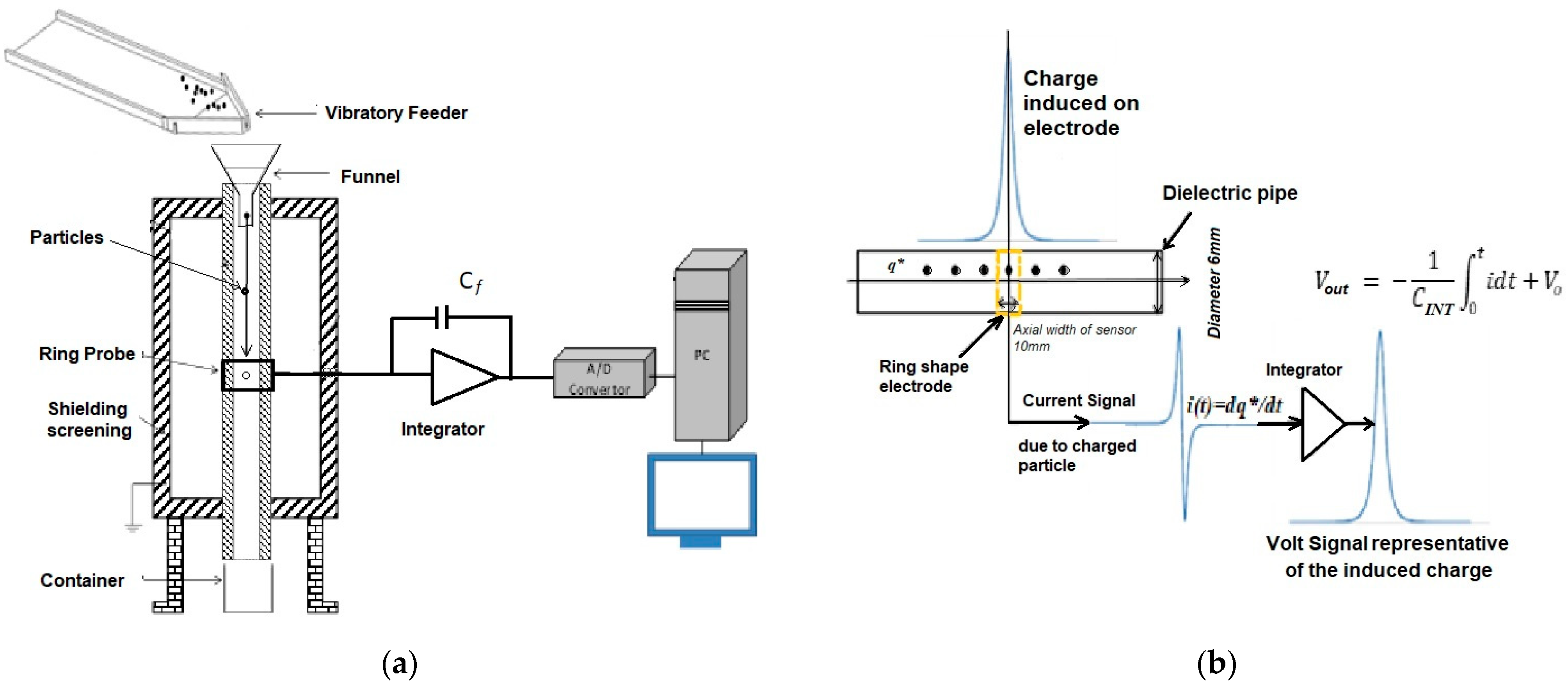
An inductive charge sensor was designed to detect triboelectric charge accumulation (such as the fine powders experienced during sieving or other handling operations), between the particles and the constraining surfaces, under controlled laboratory conditions, particularly in terms of charging actions and environmental conditions (humidity and temperature) [
31,
32]. The sensor consists of an inductive sensor ring, a pure integrator, and signal data acquisition, as shown in
Figure 1a. A schematic diagram of the sensor, the working principle of the charge sensor, and the sensor’s response to a single charged particles are shown in
Figure 1b. The instrument also consists of a particle delivery tube and a shielding screening box, in which the tube is about 200 mm long and 6 mm in diameter. If each particle passing through the ring sensor has a charge of ±
q, with the feedback capacitor
Cf of 10 pF, the value of individual particles passing through the detector will result in pulses of the magnitude ±
q/
Cf volt. The voltage signal can be recorded and used for the charge detection.
3.3. Experimental Method
Triboelectric charging of powders is complicated, and is subjected to many conditions, such as contact surface materials, actions between the contacts, and the environmental conditions when the powders are charged. A repeatable method was used for charging the powders to the highest levels by vibrating the test samples in a specific test container made of a certain contact material, such as stainless steel. In the tests, the samples were charged by agitating in the test container using a vortex mixer (Grant Instruments Ltd., Cambridge, UK). According to the materials of which the container is made, the powders are charged in a different way (positively or negatively) or to a different level of charge; in the case where the container can be made of copper, stainless steel, polyvinyl chloride (PVC) or glass, etc. A sample of about 1 g of powder is placed in the container and left on the vortex mixer to be charged at 1500 rpm for 10 min. About 1–10 mg of charged sample powder is taken and introduced into the sensor. A charge signal in voltage generated by the sample is recorded by a data acquisition system in MATLAB (MATLAB R2018b) at a sample rate of 10 kHz for a period of 6 s while the sample is fed into the sensor.
The sample is then collected immediately and weighed on an electronic scale with an accuracy of up to 0.1 mg. The charge-to-mass ratio (
CMR) and the charge polarity distribution can be detected from the charge signal. For electrostatic charge of powders, the
CMR is used in assessing ‘chargeability’ of the particles, which can be expressed as follows:
where,
CMR is the charge-to-mass ratio (C/kg, coulomb per kilogram),
m is the mass of test sample (kg), Δ
Vo is the output voltage (V) from the charge sensor, and
Cf is the feedback capacitor (F) of the virtual earth amplifier used for the sensor. In the study, pC/g is used for the results, which is equal to 10
−9 C/kg.
While the sample materials were being prepared for charging, the humidity and temperature in the room were recorded. In the case of controlling the test environment, conditioning of the room needs to be taken prior to the measurements so that the tests can be undertaken at the desired test conditions. Measurements were taken for 10 repeats. Averaged CMR was calculated with a standard deviation. Charge polarity was also detected in the measurements to identify unipolar charge or bipolar charge. For the current study, all tests were undertaken at ambient conditions, at a temperature of about 20–25 °C and relative humidity (RH) of about 35–45%, monitored by a sensor (Hygropalm-HP21, PST, Process Sensing Technologies (PST UK) Crawley, UK).
3.4. Sample of Powders
Six fine powders were investigated, as shown in
Table 1, which were suspected to have electrostatic charge problems. Particle size distributions (PSD) and the specific surface area of the sample materials were measured by the laser diffraction method (Mastersizer 3000, Malvern Panalytical, Ltd., Malvern, UK) with a dry dispersion unit. A sample of approximately 10 g was used for five repeats measured at 2 bar air pressure and 60% feed rate. An averaged result was used for the study.
The solid density of the sample materials was measured using a gas pycnometer (Ultrapyc 1200e, Quantachrome Instruments, Boynton Beach, FL, USA) with nitrogen gas. The measurement was repeated five times, and an average value was taken with a standard deviation of about 0.05% of the measurement.
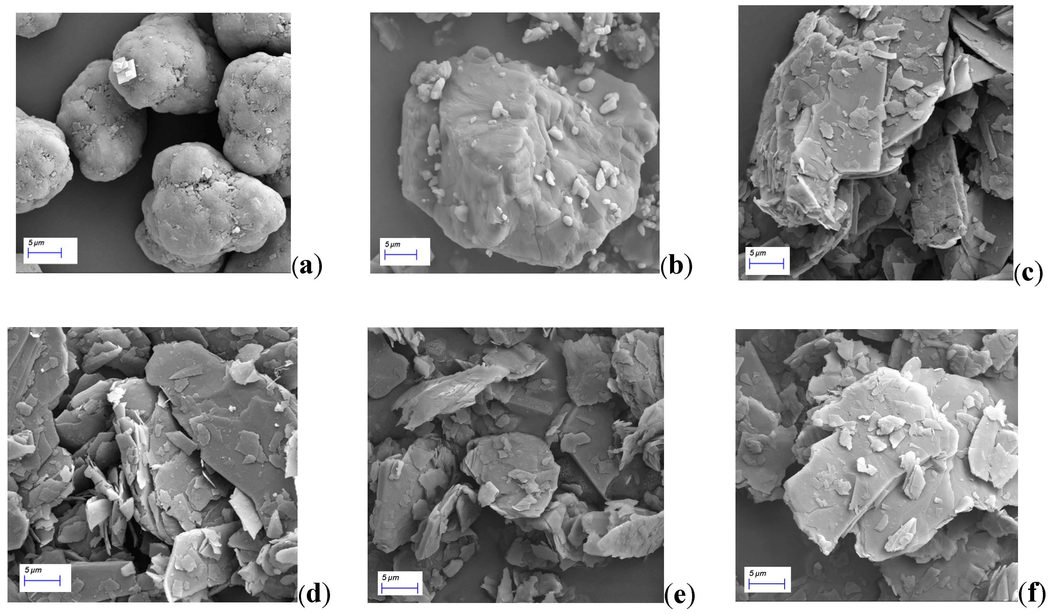
The SEM images were captured on a JSM-5510 Scanning Electron Microscope (JEOL (Europe) BV, Zaventem, Belgium), which are shown in
Figure 2. The images of the powders were taken on aluminium stubs using double-sided carbon tape and coated with a 5 mm layer of gold/palladium (Au: Pd ¼ 80:20). The instrument was operated at an accelerating voltage of 10 kV, and the images were taken at a magnification of 2000.
4. Results and Discussion
In this study, two types of powders were studied: polymer powder (AP and DS) and mineral powder made up mainly of magnesium, silicon, and oxygen (talcum powders). Charge levels and polarity distributions of the powders in storage and against different contact surfaces were detected. The results are discussed in terms of averaged CMRs.
4.1. Powder Charge Detection
The charge density and the charge polarity of a powder can be detected simultaneously when a charged sample is introduced into the inductive charge sensor.
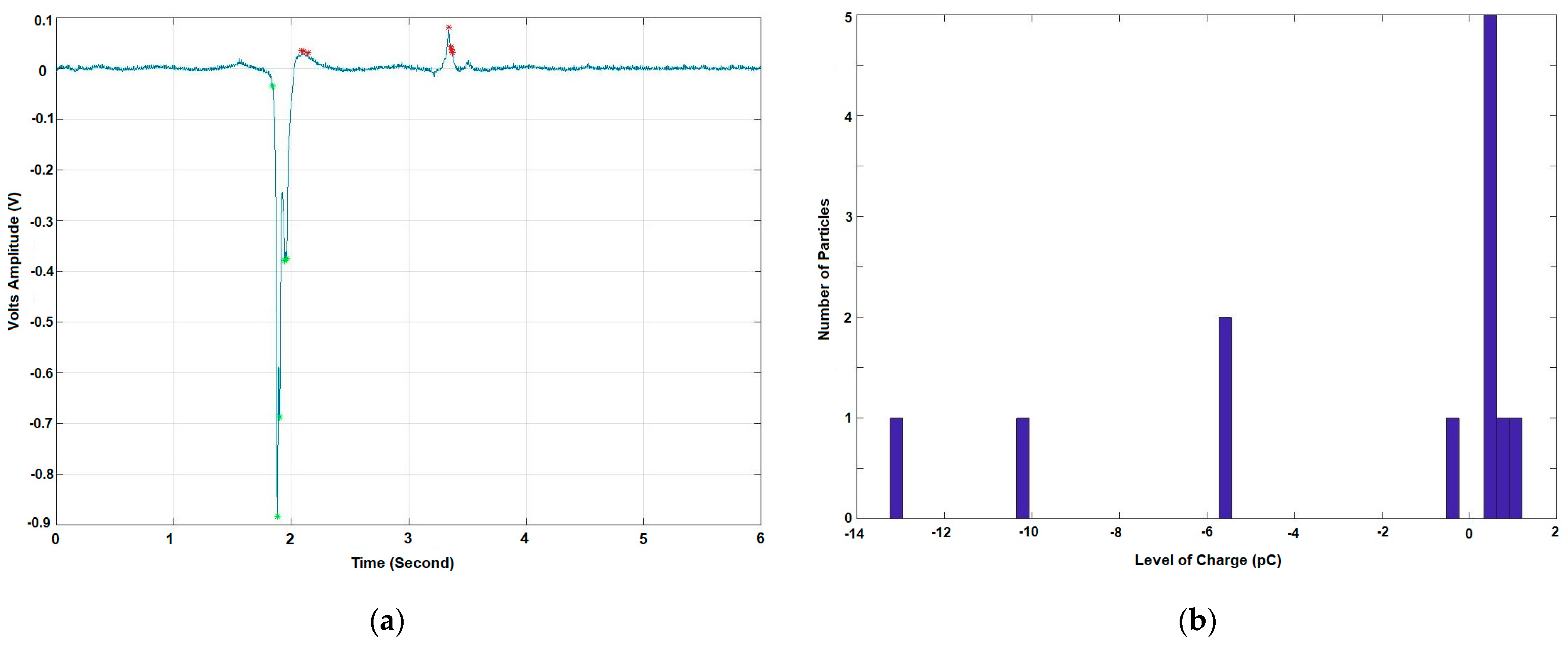
Figure 3a shows the processed charge signal of the polymer powder (DS) from the storage bags directly. The results demonstrate the detection of charged powder with a small sample (about 1–10 mg during each test). It clearly shows the charge impulses generated by the particles or the clusters. The voltage signal produced undoubtedly indicates the charge polarity of the particles. Principally, charging of different materials is based on their work functions [
3]. In fact, the triboelectric charging of powders is complex due to the multiple contacts between particles and the surfaces, especially for a multiple-particle system. By counting individual particles in terms of the level of charge, a charge distribution can be given as the number of particles or clusters at different charge levels, as shown in
Figure 3b.
In
Figure 3b, the levels of charges are classified as negative and positive charge. As shown, there are five negatively charged particles or clusters and seven positively charged particles or clusters. Therefore, the total negative and positive charge can be processed in terms of the charge polarity, which is counted as one measurement. The measurement gives information on the levels of negative, positive, and net charge densities using the mass of the test sample.
4.2. Charge Density and Charge Polarity
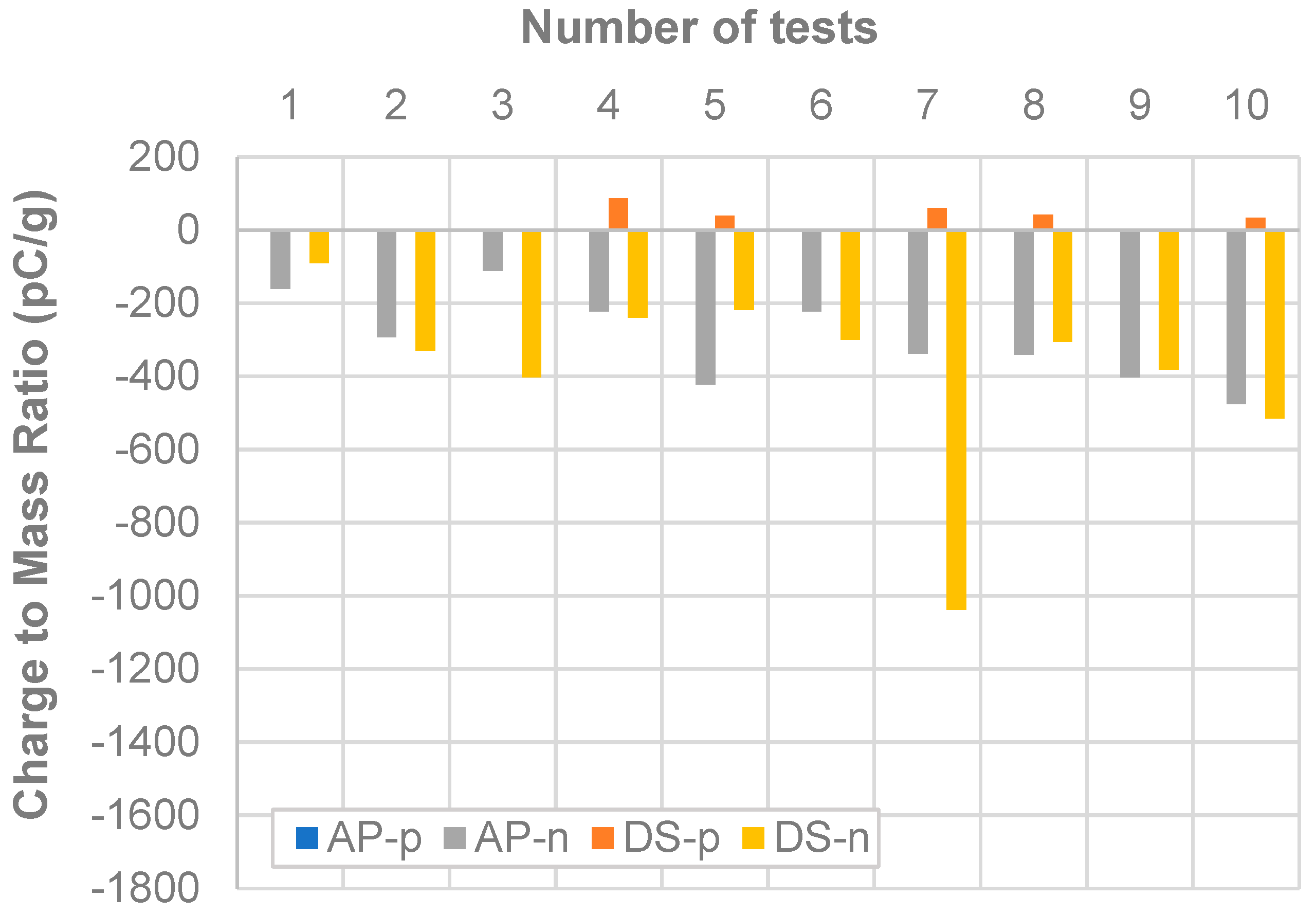
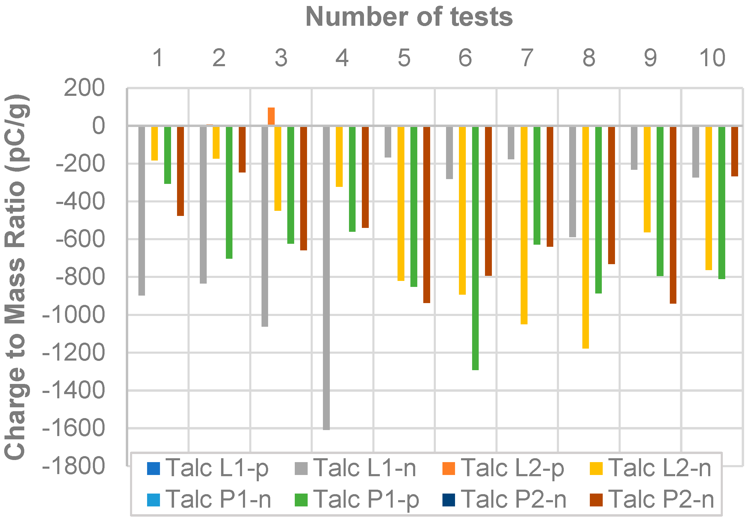
The measurements were applied to different samples of polymers and the talcum powders for electrostatic charge detection at ambient conditions. In the study, 10 repeated tests were undertaken at uncharged conditions, in which the powders were taken directly from the storage bags and measured immediately. This measurement represents the fact that the powders have been relaxed for a long time in storage and are at the initial conditions before entering any process. The results for the polymer powders are shown in
Figure 4 and the results for talcum powders are shown in
Figure 5.
The results show that the polymer powder (AP and DS) has a relatively lower charge in nature compared to the talcum powders. It shows to be about 50% lower than the charge level for talcum powders. The talcum powders have similar charge levels and polarity, large negative and tiny positive charges. DS has a small positive charge behaviour.
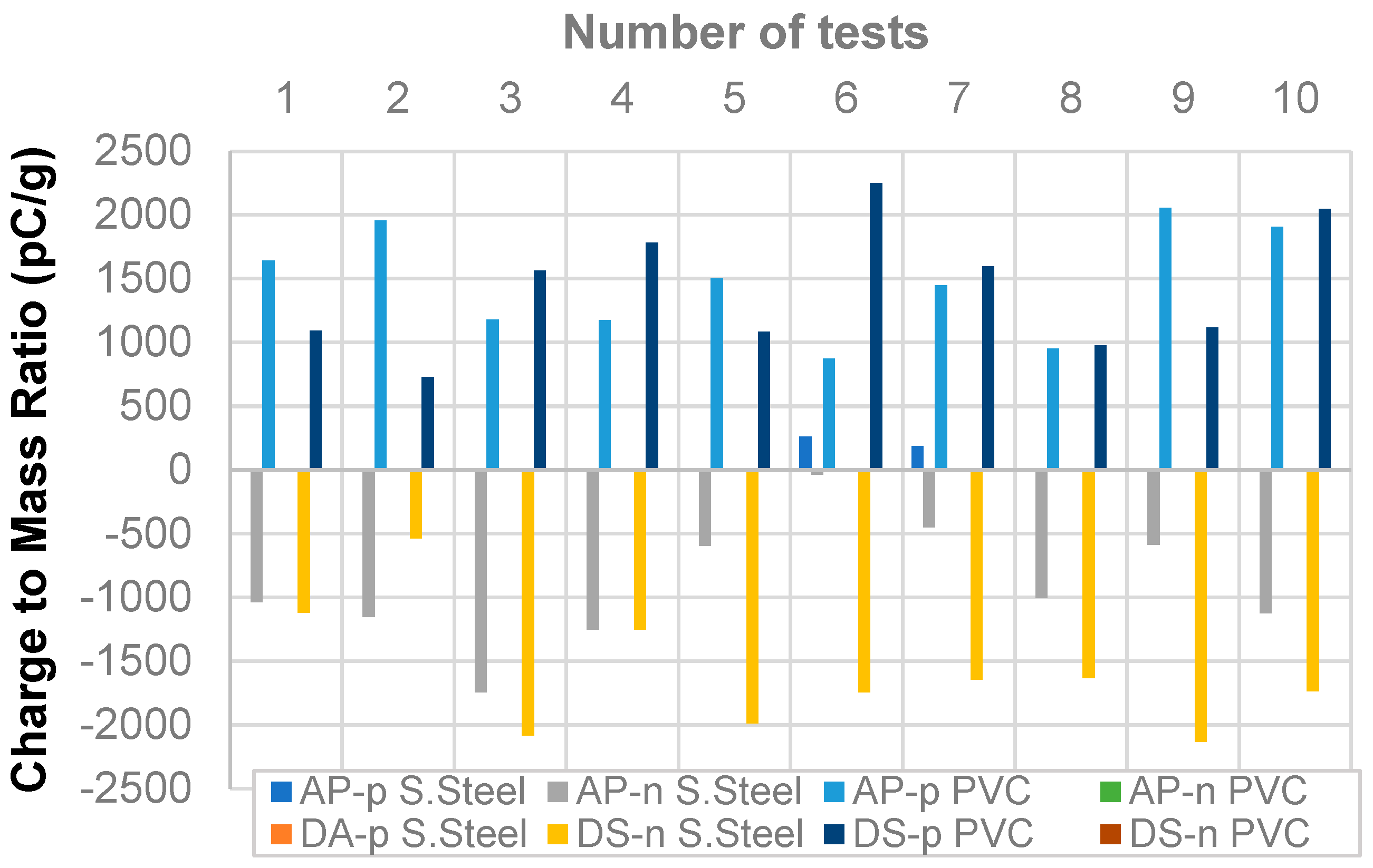
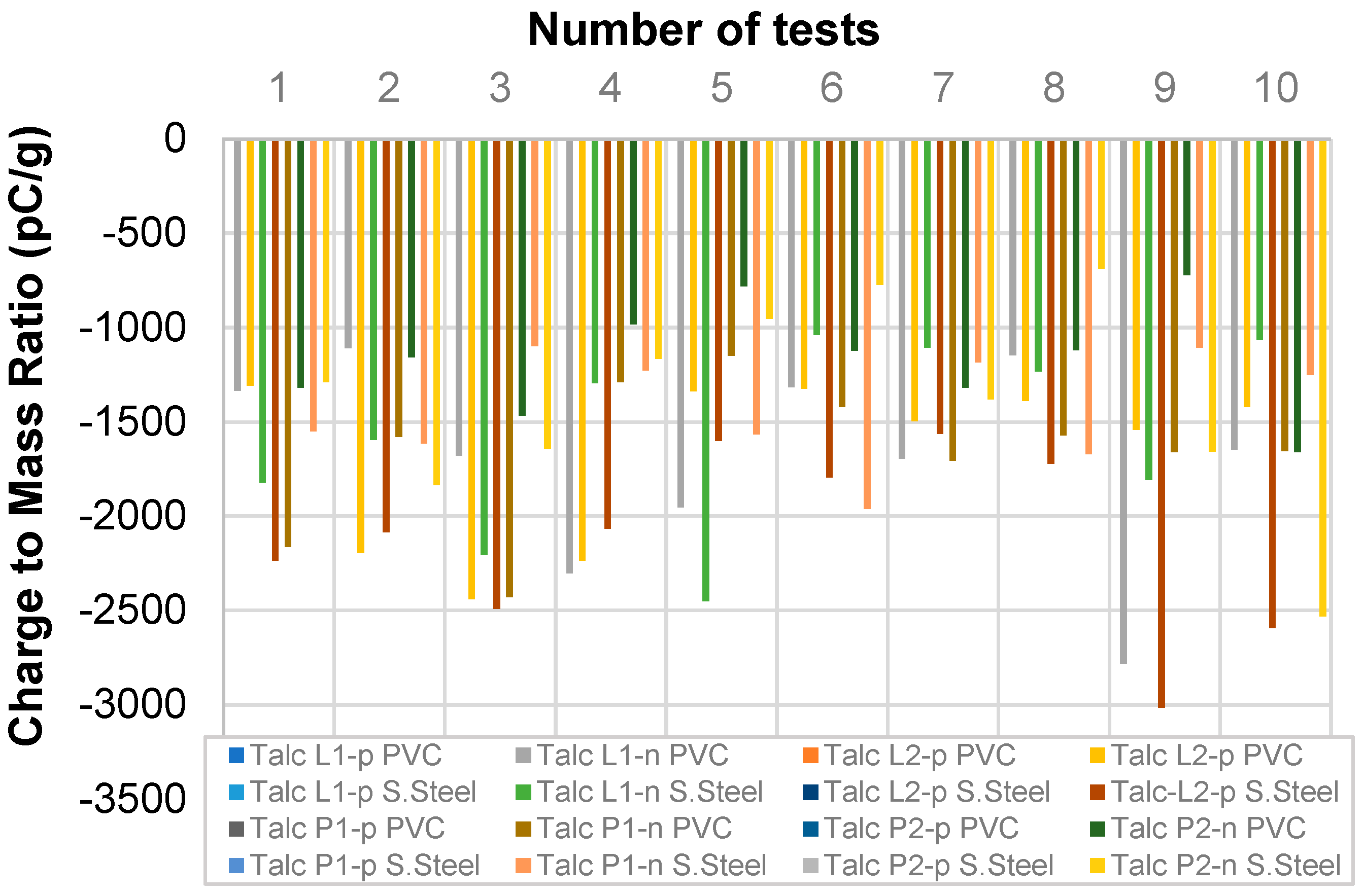
4.3. Charging against Different Contact Materials
The results shown in
Figure 4 and
Figure 5 indicate that the powders can hold significant static charges in storage bags, although the powders are stored in storage for a long time and have not been charged in any tribo-charging actions. An extended study was undertaken when the powders were rubbed against different contact surfaces. In this study, two contact surfaces were studied, one was polyvinyl chloride (PVC), and the other one stainless steel 304 (S. Steel). The samples were stored in PVC or S. Steel containers and charged under vibration at 1500 rpm for 10 min. The charged particles were tested using the inductive charge sensor. The measurement results are shown in
Figure 6 and
Figure 7 for the 10 repeated tests with the charge levels and the charge polarity. The results in
Figure 7 show the polymers, and the results in
Figure 8 show the talcum mineral powders.
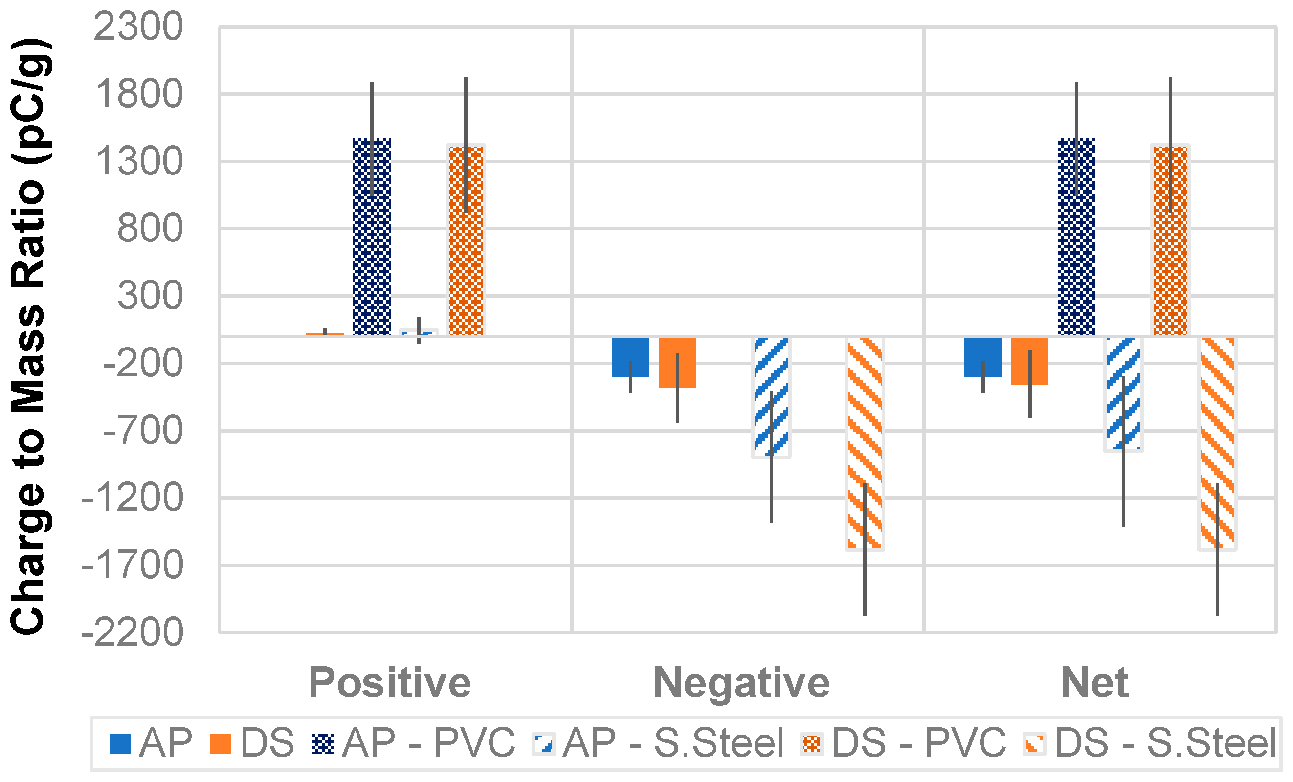
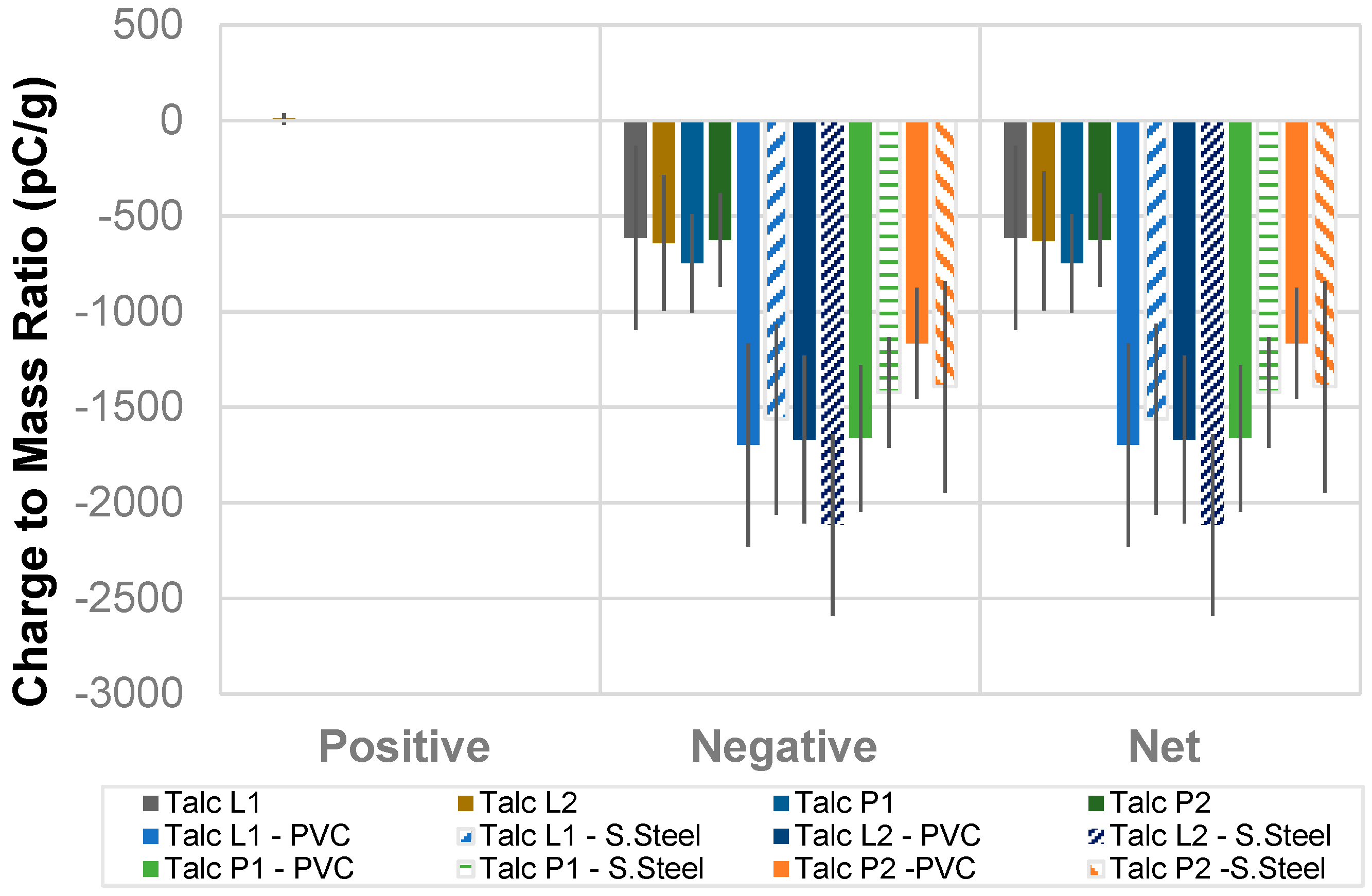
The results of the overall charge levels and polarity distribution are shown in
Figure 8 and
Figure 9. The results in
Figure 8 represent the charge levels on polymer powders, and results in
Figure 9 are for the talcum powders. The charge levels are calculated in terms of the charge polarity and shown as positive, negative, and overall net charge. The results indicate that the tribo-charging against surfaces adds charge to the powders. Different surfaces may add different levels of charging or even different types of charging to the powders. In this study, interactions (rubbing) between the powders and the surfaces only increase the charging levels but do not change the charge polarity. The average charge levels for charging against the PVC and the S. Steel surfaces increased about three times compared to the charge levels in storage. However, small positively charged particles could be detected, especially for the polymer powders. This means the charging actions can increase the opposite charge and cause agglomeration in powders.
4.4. Fine Powder Charging and Detection
Most powders can suffer from electrostatic charging in handling processes, especially fine powders. Electric charge on powders can remain for a long period of time. In a process, when powders are in contact with other surfaces such as equipment, triboelectric charging is likely to be the main reason leading to electrostatic charging hazards.
For smaller particle size, powders are more likely to be affected by the electrostatic force because of the large surface area and small mass of the particles. Because the charging can have different charge polarities, powders can appear as unipolarly charged or bipolarly charged. It can be difficult to determine the charge polarity in powders when the charged particles are agglomerated and appear to have an overall net charge. Traditional methods are used to apply a high-strength electric field to separate the particles so different charged particles can be detected and measured. However, the electric field may add additional charges to the particles as the electric field generates charging actions on the particles. Without influencing the particles, charge measurements for fine powders need extra consideration, especially in representing the conditions in a process when the powders are in contact with other surfaces.
In this study, an inductive charge sensor demonstrates the advantages in determining particle charging levels and charge polarity distributions using small samples. The results in
Figure 3 and
Figure 4 show that a charged particle/cluster can induce a charge signal, which shows the charge level and the direction of the particle/cluster as a positive or a negative charge. The charges over numerous particles can be accumulated in terms of charge polarity, so a CMS with the charge polarity can be determined for the sample powder. With multiple measurements (10 repeats in this study), a distribution of charge measurements can show the charging behaviours for certain test conditions. In the storage conditions, two types of powders studied, a polymer powder (AP and DS) and a mineral powder (talcum) show that both the powders have negative charges remainingd, but the talcum powders have a high level of electric charge.
In the study of triboelectric charging against a surface, the polymer powder (AP and DS) shows a different charging behaviour compared to the talcum powder. When in contact with a stainless-steel surface, both powders gained negative charges, and the charge levels were increased 2–3 times. However, when tribo-charging against a PVC surface, the polymer powder (AP and DS) was shown to be positively charged, but the talcum powder showed the same charge direction as in the case with contact with the stainless-steel surface. The charge levels of the talcum powders against the PVC surface are slightly lower than that of the charge levels in contact with the stainless-steel surface. In the study, the Talc P2 has a small particle size and a high surface area, which should give a high charge level. However, the results show that the Talc P2 powder has a similar charge level to the other talcum powders. This may be due to a high agglomeration in the Talc P2 powders, which generates a shielding effect and reduces the charging appearance on the powders.
This study shows that fine powders are easily influenced by electrostatic charging in a process. Charge detection for fine powders can be difficult because of agglomeration in the powders. The inductive charge sensor can work with powders and has advantages in charge polarity detection and rapid measurement of multiple samples. The measurement results for two types of fine powders demonstrate the advantages of the inductive charge sensor for electrostatic charge measurements of fine powders.
5. Conclusions
Electrostatic charging of powders can be a serious problem in industrial handling processes, especially for fine powders. It is hard to characterise the electrostatic charging properties of fine powders. The charging hazards for powders can be as serious as causing an explosion, but often lead to extra particle agglomerations and material deposition on a surface.
Traditional charge measuring devices have had difficulty in measuring charge polarity distribution in powders. The inductive charge sensor demonstrates the advantage of determining charge levels and charge polarity for fine powders using a small sample. The measurement can be repeated rapidly for multiple tests, so a charge distribution can be measured in terms of the charge polarity.
An evaluation study was undertaken. The measurement results for two types of fine powders showed that both powders had a small negative charge in storage conditions. When triboelectric charged against stainless steel surface, the powders were charged negatively. The charge levels in powders were increased 2–3 times, but the charge polarity was not changed. When triboelectric charging against a PVC surface was measured, the polymer powders (AP and DS) were charged positively, but the talcum powders remained negatively charged with a slightly lower level compared to the charge level against the metal surface.


