
Superferromagnetic Sensors
1
Bogoliubov Laboratory of Theoretical Physics, JINR, 141980 Dubna, Russia
2
Nuclear Physics Department, Dubna State University, University str., 19, 141982 Dubna, Russia
*
Author to whom correspondence should be addressed.
Nanomanufacturing 2023, 3(3), 263-280; https://doi.org/10.3390/nanomanufacturing3030017
Submission received: 23 March 2023
/
Revised: 28 May 2023
/
Accepted: 12 June 2023
/
Published: 24 June 2023
Abstract
:The strong ferromagnetic nanoparticles are analyzed within the band structure-based shell model, accounting for discrete quantum levels of conducting electrons. As is demonstrated, such an approach allows for the description of the observed superparamagnetic features of these nanocrystals. Assemblies of such superparamagnets incorporated into nonmagnetic insulators, semiconductors, or metallic substrates are shown to display ferromagnetic coupling, resulting in a superferromagnetic ordering at sufficiently dense packing. Properties of such metamaterials are investigated by making use of the randomly jumping interacting moments model, accounting for quantum fluctuations induced by the discrete electronic levels and disorder. Employing the mean-field treatment for such superparamagnetic assemblies, we obtain the magnetic state equation, indicating conditions for an unstable behavior. Respectively, magnetic spinodal regions and critical points occur on the magnetic phase diagram of such ensembles. The respective magnetodynamics exhibit jerky behavior expressed as erratic stochastic jumps in magnetic induction curves. At critical points, magnetodynamics displays the features of self-organized criticality. Analyses of magnetic noise correlations are proposed as model-independent analytical tools employed in order to specify, quantify, and analyze the magnetic structure and origin of superferromagnetism. We discuss some results for a sensor-mode application of superferromagnetic reactivity associated with spatially local external fields, e.g., the detection of magnetic particles. The transport of electric charge carriers between superparamagnetic particles is considered tunneling and Landau-level state dynamics. The tunneling magnetoresistance is predicted to grow noticeably with decreasing nanomagnet size. The giant magnetoresistance is determined by the ratio of the respective times of flight and relaxation and can be significant at room temperature. Favorable designs for superferromagnetic systems with sensor implications are revealed.
1. Introduction
Advances in micro- and nano-fabrication of various materials stimulate the extensive development and employment of spintronic magnetoresistance sensors and/or magnetoresistive sensors (MRS) for both recording and non-recording purposes. Such state-of-the-art magnetoresistive spintronic sensors have a high sensitivity of the detected ultra-weak field, which meets the requirements of intelligent sensor applications in the fields of the Internet, mobile devices, aeronautic and cosmic engineering, environment and healthcare, domotics, and so on. Moreover, their adaptability and miniaturization, easy integration, and cost-effectiveness put such MRS forward as exclusively favorable in terms of spreading applications and commercial production.
In particular, the recent progress in ligand-stabilized frameworks (e.g., mono-carbon [1,2] or thiolates [3]) and the employment of porous materials [4] (zeolites, covalent- and metal-organic architectures, etc.) allows the synthesis of metallic nanoparticles of higher stability, recyclability, and selectivity, strong metal-support interactions, and the ability to facilitate tandem catalysis. In the case of the transition metals Co, Fe, and Ni, such encapsulated quantum magnetic metal nanoparticles display superparamagnetic features that we refer to hereafter simply as SPM. Made up of imbedded in a matrix (quasi) recurrently composed SPMs, such crystalline metamaterials and/or SPM assemblies (SPMA, cf., e.g., [5] and refs. therein) make it possible, e.g., to construct novel meta-materials demonstrating advanced characteristics beyond those in regular condensed matter. In addition to plausible improvements in ‘figures of merits’ for engineering, such SPMAs are of general importance for investigations of the structure, dynamics, and phase behavior of matter at a wide variety of characteristics, e.g., interparticle interactions, compositions, long-range Coulomb effects, etc. In particular, SPMAs with sufficiently high SPM densities exhibit superferromagnetic (SFM) structural properties, cf., e.g., [1,2,3,4,5] and refs. therein. SPMAs are important for advanced MR sensors for, e.g., medical and biological implications, storage and no-recording technologies, etc.
In this paper, we provide a brief overview of various aspects of the SPM and SFM systems as well as their implications for magnetoresistive sensors. The next section considers SPM electronic properties by employing the band structure-based shell model. In Section 3, such a description of SPMs is applied to the interpretation of the SFM features of SPMA as a result of direct and/or indirect exchange coupling. Tunneling and giant magnetoresistance effects naturally arise in such a treatment. The SFM state equation and its effect on SPMA magnetodynamics are described in Section 4. In Section 5, magnetic reactivity in sensor mode is analyzed. Conclusions and discussions are in Section 6 and Section 7.
2. SPM Shells Structure
The SPM features arise in ferri- and ferro-magnetic materials with a spatial size less than the critical size for domain development and are given by a single uniformly magnetized metal object. The electronic state of this system corresponds to a uniform magnetic alignment, and the sample behaves like a small permanent magnet. The volume of a single-domain portion of a material is determined by the substance and inputs of various anisotropy energy components. The maximum radius rc for a single domain particle can be evaluated as rc = 9 (AKu)1/2 /Ms μ0 with the exchange coupling strength A, the uniaxial anisotropy Ku, the saturation magnetization Ms, and the permeability constant μ0. The usual numbers of a radius rc for traditional elements are: Fe-15 nm, Co-35 nm, γ-Fe2O3 − rc ≈ 30 nm, and SmCo5 corresponds to considerable rc ≈ 750 nm (see [5] and refs. therein). Determined by the volume and material, the SPM magnetic moments range from 102 to 105 μB, where μB is the Bohr magneton. At sufficiently high temperatures, such a system behaves like a paramagnet [5,6], with the considerable exception that the independent moments are not those of a single atom but rather of a single domain ferri- or ferro-magnetic particle, which may contain more than 105 atoms ferri- or ferro-magnetically coupled by an exchange interaction. Such a system is then referred to as superparamagnetic, or SPM; see also above.
Shells in the Band Structure of SPM
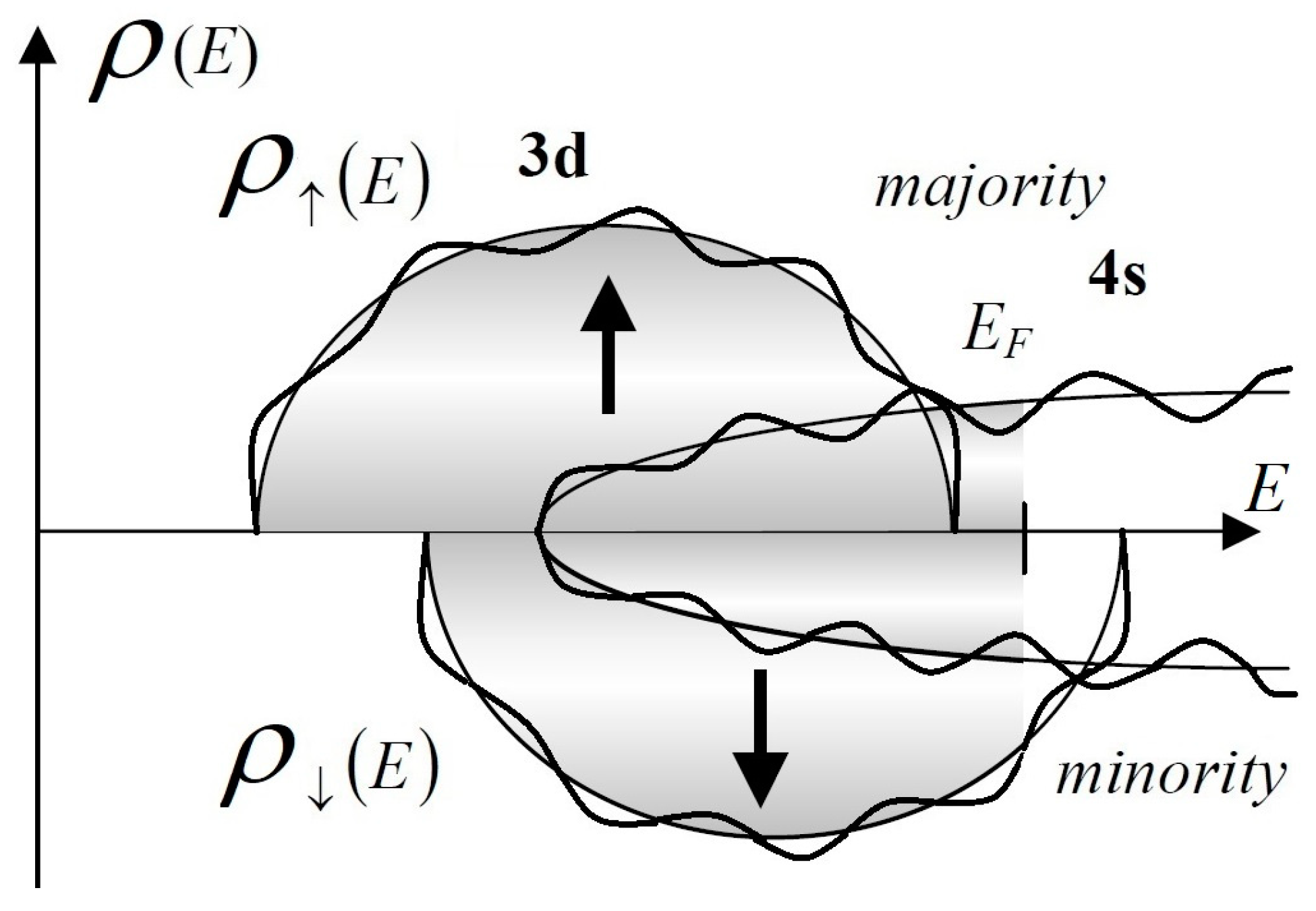
The iron series transition metals—Co and Ni—correspond to the strong ferromagnetic metals with large intra-SPM exchange interactions and, therefore, considerable molecular magnetic self-induction H. In this case, see Figure 1, the Fermi energy EF is located above the majority spin band top energy and below the top energy of the minority spin levels (cf., e.g., [7,8]). Then the magnetic moment per atom mN of SPM containing N atoms is given by mN = μB nh, with the Bohr magneton μB and the number of holes in the minority spin band nh that is related to the mean number δns of delocalized s electrons above in the majority spin band [9,10] by nh = n0h − δns with n0h = 10 − nv + n0s, where nv and n0s are the numbers of outer shell and s electrons per atom, respectively. The quantity δns can be expressed in terms of the level density contribution ρs of the sp band to the total value of active electrons.
where f(x) = [1 + exp{x/kBT}]−1 denotes the Fermi distribution function.
For a finite SPM particle, the number of s electrons n0s contains the parts of “bulk” nbulks, “surface” nsurfs, and “curvature” ncurvs constituents, i.e., n0s nbulks + nsurfs N− 1/3 + ncurvs N− 2/3. The respective parameters nis are determined by the mean coordination number of SPM atoms.
Confinement of electrons into the finite spatial SPM volume results in the well-known shell effect in the level density, cf., [11,12,13] and refs. therein. Consequently, the component of s electrons in the level density ρs can be written as
with the smooth ρssm and an oscillating ρssh (i.e., shell correction) parts, and an energy E measured from the bottom of the sp band Es. For example, when electrons are confined in a 3D-shaped SPM by a harmonic oscillator potential (HO: V(r) = m2r2/2 − ħ ), see Figure 1, at a uniform magnetic self-field H, both components can be represented as [11,12,13].
Here ℏ is the Planck constant, and the condition η = L/ ≪ 1 is ensured due to the Larmour frequency L = eH/2mc; j0 denotes the spherical Bessel function; and the suppression coefficient qk accounts for the continuousness of an electronic trajectory (cf., e.g., [14,15]) and allows for a smooth truncation of contributions from longer periodic orbits. This term can be revealed from the data of the mean-free path l or the material conductivity as qk qk with q exp{−L/l}, where L denotes the primitive orbit length (cf., e.g., [11,12,13]). The shell structure gives rise to oscillations of ns as a function of SPM size. Using the abbreviations = EF − , = − EF, and Δs = EF − Es, we can evaluate the oscillating part of Equation (2) as
where R = y/sinh(y) with y = 2πkBT/s, and Xs = (3 n0sN)1/3 determines the number of filled electronic shells. Then, the HO frequency is given by s = Δs/Xs, and exceeds significantly the value in many practical cases, cf., [11]. We refer to this model as the band-structure-based shell (BSBSh) model.
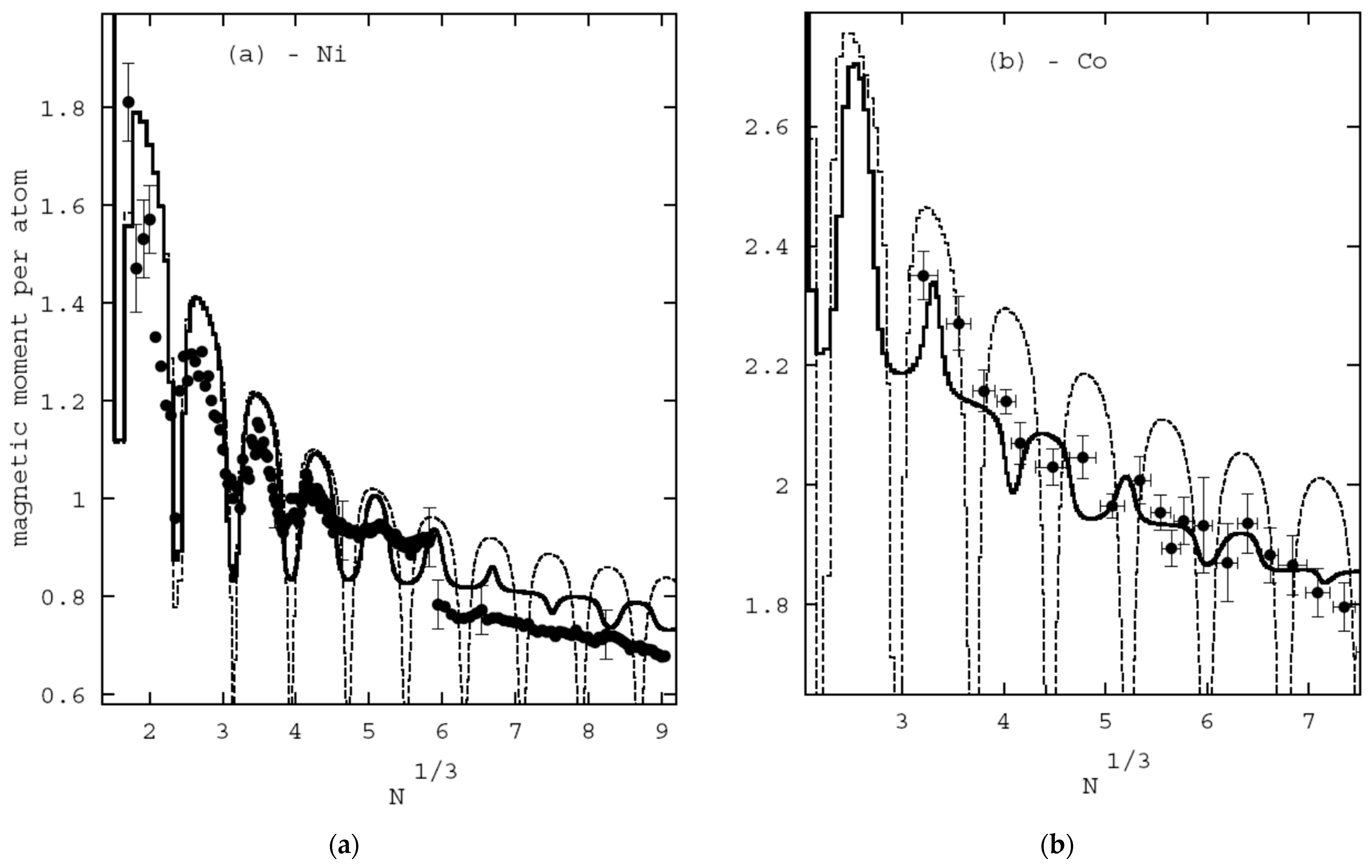
We incorporate parameters (i.e., density, conductivity, magnetization, and so on, cf., [7,8]) of Ni and Co metals into Equations (1)–(4) and evaluate the SPM magnetic moments for various numbers of atoms in nanocrystals. As is seen in Figure 2, experimental data are well reproduced by the BSBSh model, c.f., e.g., also [9,16,17,18]. In particular, SPM magnetic moment oscillations around the general trend for moment suppression with increasing SPM size can be attributed to the electronic shell effect. Such momentary oscillations are smudged out due to the magnetic self-field. This property is significant for the reasonable agreement of the BSBSh model predictions with the experimental results.
An important practical quantity of SPM is represented by spin polarization. The total value is defined as
and the differential number at the Fermi energy EF is written as
3. SFM as SPMA with Direct and/or Indirect Exchange Coupling
Since the notation SFM—‘superferromagnetism’—was used in various implications, it is worth stressing that here we consider sufficiently dense SPMA displaying a ferromagnetic long-range order. In the considered case, such a feature arises due to direct and/or indirect exchange interactions between SPM.
3.1. SPMA in Insulator Substrate
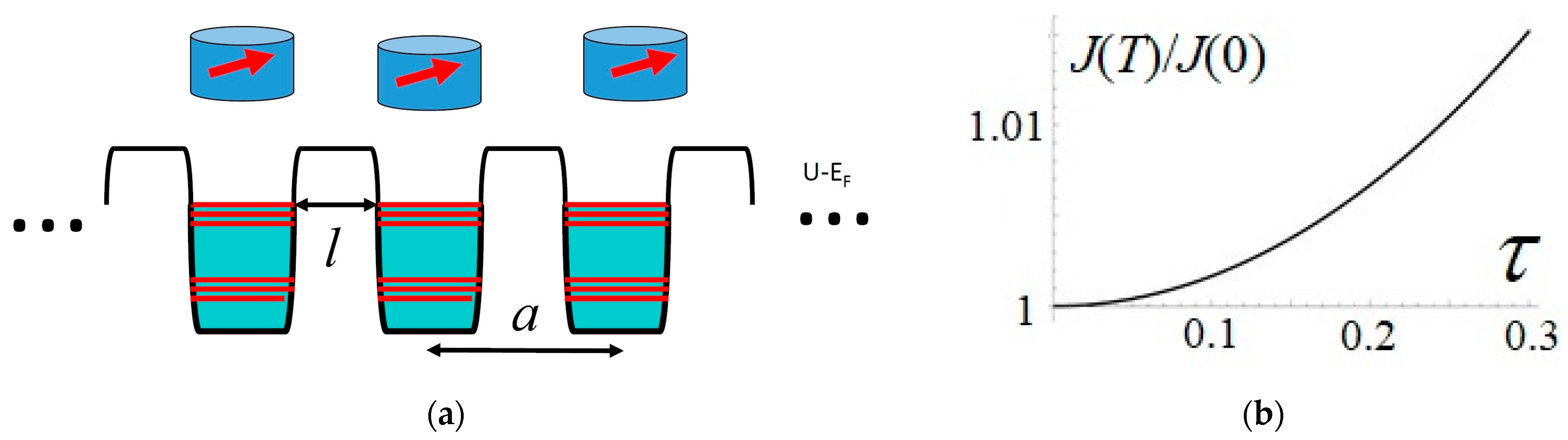
Let us consider SPMA embedded in an insulator; see Figure 3. The electronic level density is affected by the direct inter-SPM exchange coupling. At considerable SPM concentrations, such an effect can induce certain magnetic ordering in analogy with atoms in crystals. Such a property can be quantified by the superexchange interaction constant J, calculated as a difference of the respective grand canonical potentials for coupled—Ωf—and uncoupled—Ωd—SPMs.
where δρ = ρf(E) − ρ(E) gives the single-particle level density difference between a magnetically arranged and an individual SPM at the temperature T, and kB denotes the Boltzmann constant.
J = Ωf − Ωd ≈ −(kBT) ∫ dE δρ(E)· ln [1 + exp{(EF− E)/kBT}]
The noticeable superexchange coupling between SPM electronic supermoments originates from the delocalized Bloch wave function in SPMAs. Such a property represents the key effect for quantifying a change in level density. Within the Anderson localization concept (cf., e.g., [19] and refs. therein), such delocalization arises when the SPM electronic level broadening Γ is less than two values of the miniband splitting width B due to the coupling, i.e., Γ/B < 2. In realistic cases of nanosize SPMs, the condition of Bloch delocalization can be expected for many materials since the Fermi energy EF is a fairly reliable quantity.
To quantify further the SPMA electronic properties, we consider periodic SPM composition when, for the ith direction (i = 1,…, D), the period is ai. Then the delocalization effect gives rise to an additional electronic quantum number—quasi-momentum k in D-dimensions—and the valence electron quasi-energy for the Bloch state reads Eα = Eαd + E(k). Here Eαd represents the energy levels in a single SPM, with the quantum number αd defining the miniband. Consequently, the level density change of SPMA delocalization can be written as
δρ(E) ≈ ∫ Πi d(kiai/2π) [ρ(E − ∆E(k)) − ρ(E)].
For SPMAs imbedded in a nonmagnetic insulator or semiconductor substrate, the considerable heights of tunnel barriers, Ui > EF, result in a slight modification of SPM supermoment states caused by the small overlap in subbarrier regions. As a result, the miniband shape can be fitted by a cosine
where the SPM effective HO frequency ωe of confining potential, see Equation (3) and discussion therein, l denotes the tunneling length in a matrix with corresponding effective mass m* of a quasiparticle, see Figure 3, while p=[2 m* (U − EF)]1/2/ℏ gives the wave number in a substrate.
∆E(k) = Σi Bi sin2(kiai), Bi = 2ωe exp{−p l}
The integration over the wave number k in Equation (8) is limited by the region close to the Fermi energy EF because of the considerable barrier value U and tunneling distance l. Thus, for Co and Ni SPMs, one can account only for the minority spin electrons − e = ↓. Making use of Equations (7)–(9), we obtain the interaction constant for SPMA as
with τ = πT/Tα, Tα =ℏ2p/(lm*kB). The energy derivative at the Fermi energy is indicated by a prime.
J ≈ (EF − U) ρ′↓ω↓ exp{−p l} τ/sin(τ)
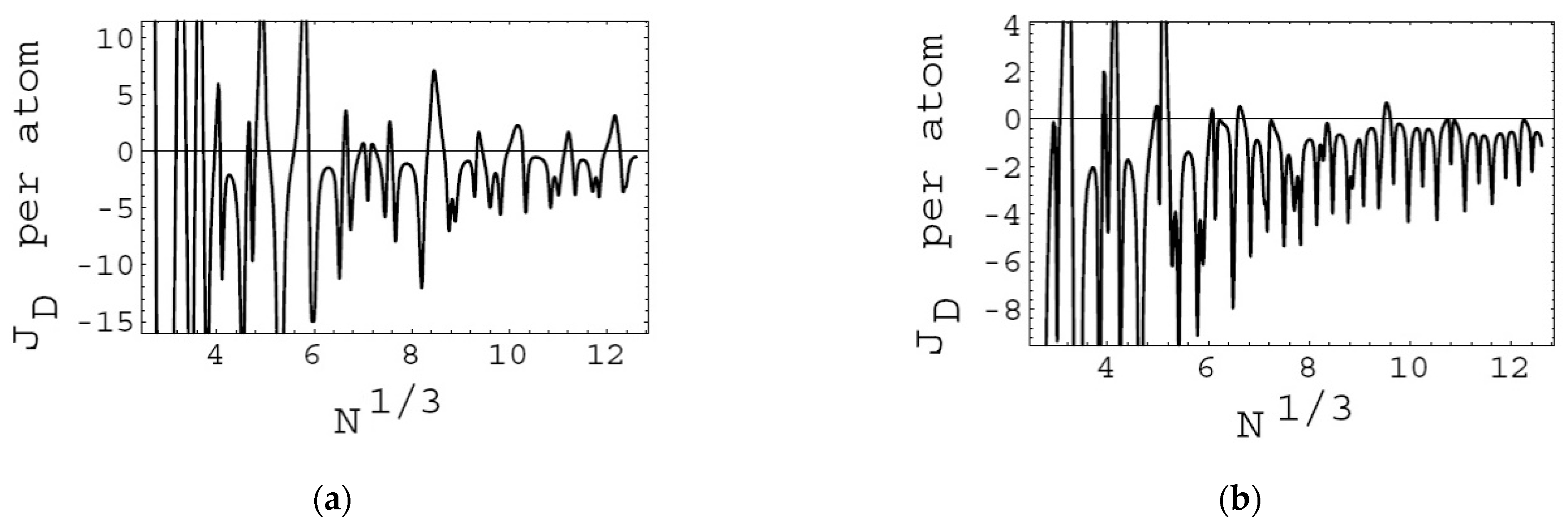
Equation (10) measures the SPMA ordering strengths arising from tunneling between the SPMs. The level density derivative ρ′↓ determines the sign of superexchange inter-SPM coupling. The respective factor in Equation (10) is illustrated in Figure 4. As is seen, the coupling constant takes preferably negative numbers, indicating, thereby, ferromagnetic ordering. Some rare positive values are smeared out due to fluctuations, size uncertainties, thermal effects, and so on. The inter-SPM coupling depends monotonically (without oscillations) on the separation distance, similarly to the magnetic interaction between ferromagnetic layers abutted by a nonmagnetic insulator. The exponential suppression of the interaction strength with growing splitting length originates from the exponentially decaying overlap of supermoment wave functions expanding their tails to the substrate. Such a feature reduces the inter-SPM splitting length when direct superexchange coupling can give rise to long-range magnetic ordering. Such a property is in agreement with experiments, cf., e.g., [1,2], where long-range superferromagnetic (SFM) ordering was observed in a system of SPMAs with sufficiently densely packed SPMs. As is evident from Equation (10), decreasing the barrier height results in exponentially growing exchange coupling strength at the same inter-SPM separations. Therefore, using, e.g., a semiconductor substrate may allow one to observe the direct inter-SPM exchange coupling in SPMA of less dense packing (because of lower tunnel barriers and a smaller effective mass m∗) as compared to an insulator matrix. For instance, the barrier value in carbon can be reduced up to ~1 eV (cf., [20]), and the magnetizing field would increase by the factor ∼ exp{5.7l/nm}. Finally, the interaction strength J grows with rising temperature. Such a behavior is caused by the exponentially increasing tunnel exchange current at higher energy levels. The finite temperature pumps the electrons effectively up to an energy region kBT above the Fermi energy EF at the expense of suppression in the occupation of the energy levels below EF. Such rearrangement changes the inter-SPM superexchange coupling strength. Since the barrier penetration factor in Equation (10) grows for higher energies, i.e., for the levels above, the factor JB strengthens as a function of temperature. We point out that the SPM structure factor is expected to decrease with increasing temperature because the shell structure of the SPMs is washed out. This may lead to a nonmonotonic temperature dependence of the inter-SPM superexchange coupling constant. At reasonable SPM size (~nm), the level density increases with energy, and the resulting negative value is associated with superferromagnetic SPMA ordering. Hereafter, we refer to such ferromagnetic SPMAs as superferromagnets (SFMs).
TMR Tunneling Magnetoresistance
The above-considered tunneling coupling between SPMs implies the dependence of the tunneling current on SPM magnetization alignment. Quantitatively, we define this phenomenon as
where R and G denote resistivity and conductivity, respectively.
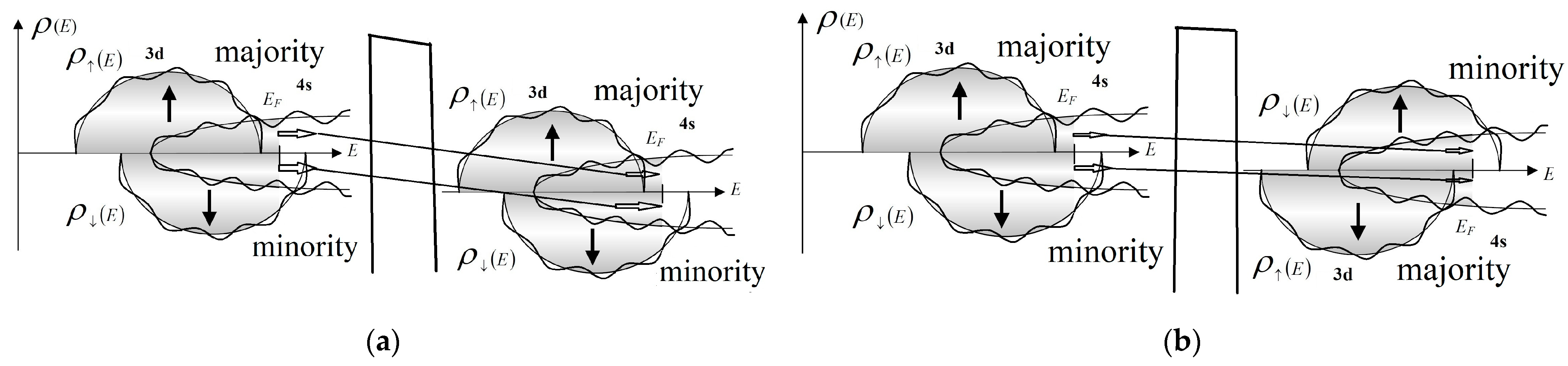
For ferromagnetic layers separated by an insulator, such an effect was first observed by M. Julliere [21]. The interpretation is based on an assumption of spin conservation and proportionality of the conductance between samples 1 and 2 to products of respective level densities , see Figure 5. Then we obtain [20,21,22] conductivities for spin orientation—parallel,
and—antiparallel.
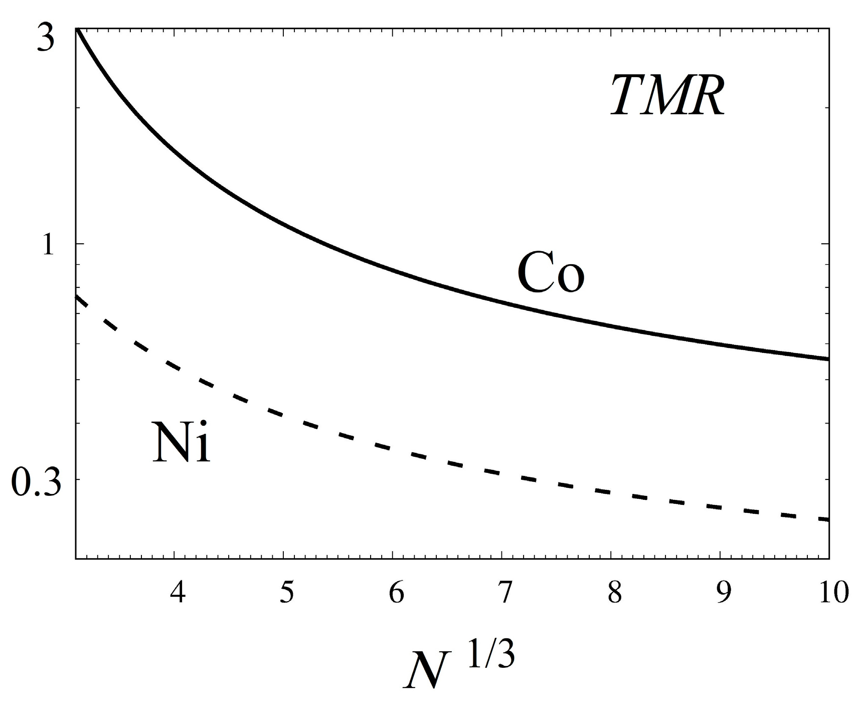
Using Equations (11)–(13), the TMR value reads
As is seen in Figure 6, TMR grows for smaller SPM sizes in the case of the iron series transition metals Co and Ni. Such a feature originates from increasing spin polarization with a decreasing number of atoms in SPM particles.
3.2. SPMA in Conducting Substrate
For conducting and/or metallic substrates, SPMs are coupled by the RKKY (Rudermann–Kittel–Kasuya–Yosida) indirect exchange interaction of a strength.
with constants and , while denotes the Fermi wave vector of the host metal. Such a magnetic interaction arises from the scattering of conduction electrons by SPM fields and oscillates strongly with the distance d between super-spins. Cases of noble metal (Au, Ag, Cu, or Pt) substrates weakly diluted with SPMs lead to super-spin glass (SSG) materials. Such a SPM–SSG phase transition has been identified in various systems of aggregated SPMs, e.g., [23,24,25]. The divergent relaxation time and the abruptly increasing nonlinear magnetic susceptibility at the transition temperatures agree well with the laws of the ‘classical’ paramagnetic-spin-glass phase transition. The observations of the relevant memory effect, identical to the canonical spin-glass effect, support the existence of a true thermodynamic transition in SPM assemblies. In ferromagnetic fine-particle systems, such an SSG state has also been observed in frozen ferrofluids; see [5].
When SPMA approaches the percolation limit at growing SPM densities, a long-range magnetic order originates from the nearest-neighbor links swamping through the whole sample together with each magnetic SPM. In such SPMAs, the cluster-glass phase develops from a SPM cluster and consequently re-enters the frozen (disordered) phase out of another, not paramagnetic, state [5].
The transition from single-particle blocking to collective freezing arises in SPMA at sufficiently dense packing of SPM particles due to the non-negligible magnetic inter-particle interactions. As is outlined above for a magnetic coupling of intermediate strengths, the randomness of particle positions and orientations, and a sufficiently narrow size distribution, one can observe a super-spin glass state. With further increasing SPM density, but prior to physical percolation, a ferromagnetic (FM) domain state appears because of the further growing strength of the inter-particle interactions. Such FM-like correlations are built on “supermoments” of the SPM nanoparticle instead of atomic moments. We refer to this FM state in SPMA as “superferromagnetism” (SFM) as well. Thus, the ferromagnetic domain with the atomic moments replaced by supermoments of the individual SPM nanoparticles determines the superferromagnetic (SFM) domain. Such a concept implies that the SPM nanoparticles or SPM remain single-domain while the ensemble displays a collective SFM feature.
GMR Giant Magnetoresistance
The giant magnetoresistance (GMR) effect was initially found in magnetic multilayer systems [26,27] and also in metallic matrices filled with magnetic particles [28]. The implications of non-magnetic conductive gel matrices for magnetic nanoparticles, i.e., SPMs, had considerable GMR effects, as reported in [29]. It is worthy of notice here that such ensembles of SPM particles display SFM properties [1,2,3,4,5,29]. Despite significant efforts to understand these phenomena, the origin of GMR is still under debate.
We consider here the transport of spinless quasiparticles (qp) between two SPMs labeled 1 and 2 and located at a distance l along the x-axis in a planar geometry. In the vicinity of ith SPM particle with local magnetization of a field strength Bi perpendicular to the plane, the qp state |i〉 corresponds to the Landau level (LL) of an energy wL = μB B/m with the Bohr magneton μB and effective mass m in units of electronic mass me, i.e., m = mp/me. In a case of vanishing mass m [30], the respective energy becomes (2 vF B)1/2. Hereafter, we use the natural unit e = = 1, unless indicated otherwise. It is worthy to notice that at typical strength B ~ 1 kG and the Fermi velocity in, e.g., graphen vF = 106 m/s, the value wL ~ 103 K.
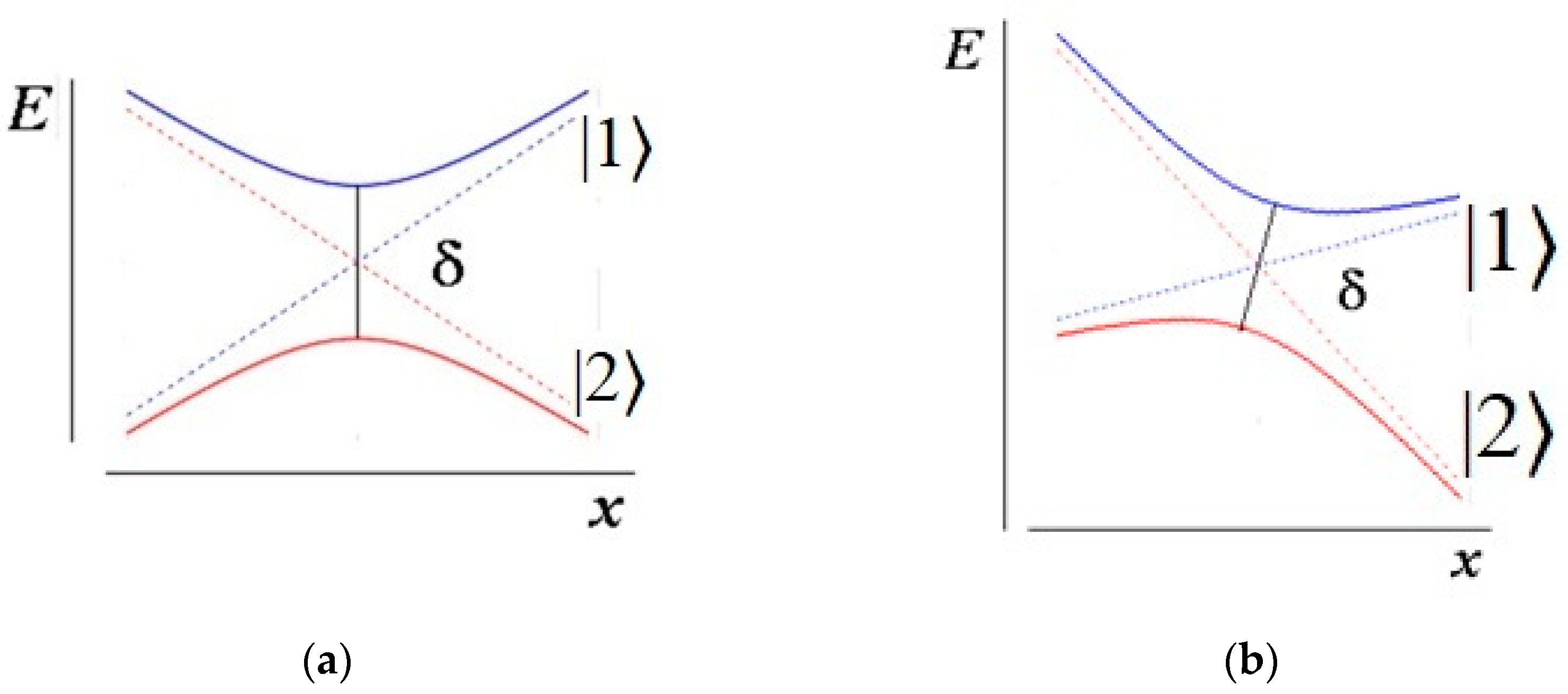
At low temperature T < wL and density, only the lowest LL (LLL) is occupied. For the parallel direction of SPMs, when B1 = B2, the energy of LLL states displays smooth spatial behavior when the resistivity is determined by the relaxation time τrel. For an anti-parallel SPM orientation, with B1 = −B2, the field-up E1 and down E2 LLL diabatic terms |i> cross, see Figure 7. Such a case implies the blocking of a current. However, at a crossing point, fluctuations prevent the crossing of adiabatic terms. The respective level splitting is characterized by a quantity δ that is determined by the off-diagonal matrix element of the two-level system’s Hamiltonian coupling and corresponds to half the distance between the two unperturbed eigenenergies at the avoided crossing point. The respective value can be considered a fluctuating quantity [31]. To test also a sensitivity to the properties of a system, we use a very general form for splitting δ distribution according to
where Cn is the normalization coefficient, and parameter n is determined by symmetry conditions: a unitary ensemble corresponds to the Wigner distribution and yields n = 1, whereas orthogonal and simplectic ensembles correspond to n = 0 and n = 3. Neglecting zero-point vibrations at a considerable temperature T, the fluctuation-dissipation theorem [31] yields the relation R2 = T/τrel.
W(δ) =Cn (δn/Rn+1) exp{− δ2/R2}
Let us consider the qp dynamics between such anti-parallel SPMs 1 and 2. The remaining qp on an adiabatic LLL term corresponds to a free electric current with regular relaxation. Evidently, a transition to the upper adiabatic term corresponds to the blocking of a current. Using the Landau–Zener–Stueckelberg formula [32], the probability Pj of transition between adiabatic terms is given by,
Pj = exp{ −2π Γ}, Γ= δ2/|d(E1 − E2)/dt|.
For free path qp dynamics, |dEi/dt| = |dEi/dB| |dB/dx| |dx/dt| = EF/τp, where τp = l/vF gives a time of flight for qp between SPMs 1 and 2 at the Fermi energy EF. Then, we have |d(E1 − E2)/dt| = 2 EF/τp. Therefore, for the average probability of current conservation, which determines the conductivity, we can write,
Using Equations (16)–(18), we get
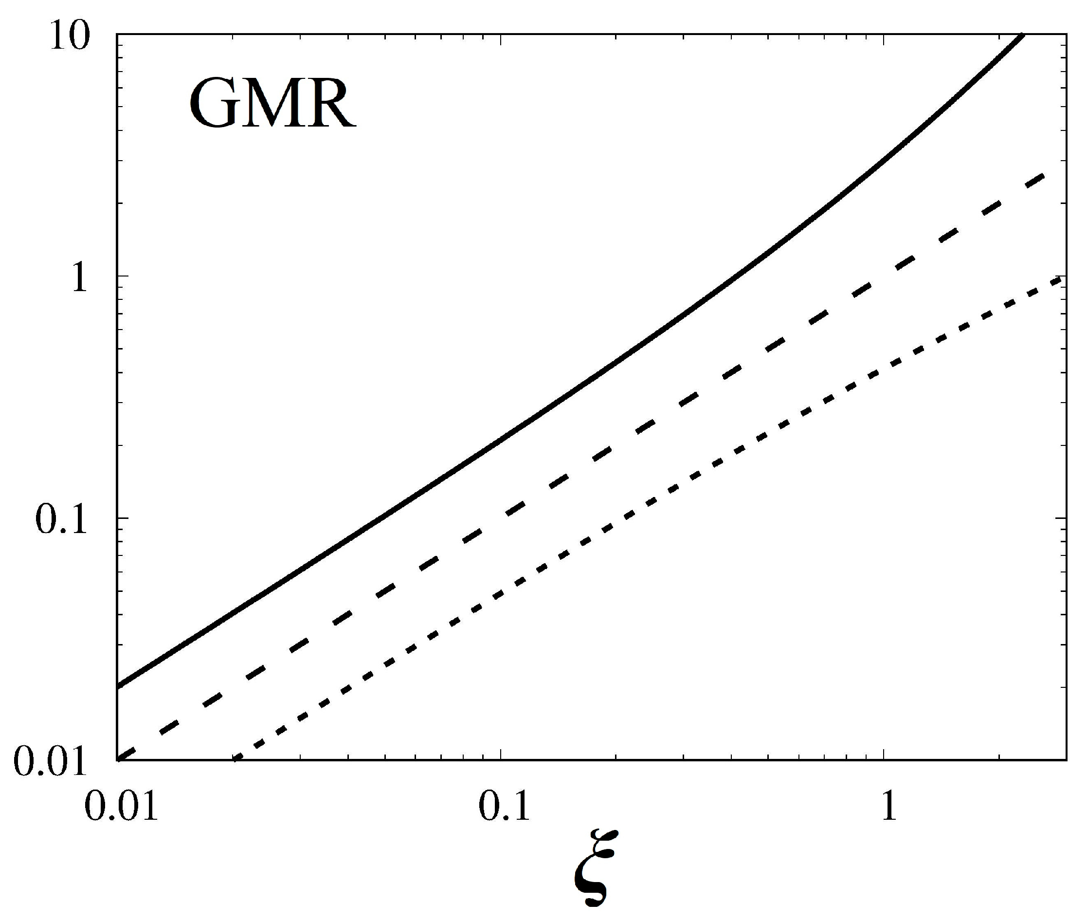
where ξ = π (T τp/wL τrel). The Pb value represents a quantitative characteristic of the conductivity ratio for the antiparallel and parallel orientations of the SPM Pb = . Then we obtain
Pb = (1 + ξ)−(n+1)/2
As can be seen in Figure 8, the blocking effect of the electric current on the antiparallel orientation of the SPM increases with an increase in the parameter ξ. For orthogonal and unitary ensembles, such amplification occurs more smoothly than in the case of a simplectic ensemble. It is worth noticing that mixed ensembles of energy levels are usually considered. In addition, parameter n can be changed due to additional constraints on energy levels.
4. SFM as SPMA with Ferromagnetic Coupling
To analyze SPMA properties, we consider the discrete SPM magnetic moments in conjunction with the discrete electronic structure of SPMs (see Section 2). Here, determines an amplitude of the discrete SPM unit and the step function is related to the local magnetic induction . The vector of values defines the magnetic moment of the SPMA element. The conditions model discrete jumps in magnetic moment discontinuities. When ; and for SPM attends two states, and +. Systems with three discrete states correspond to the non-zero numbers and SPMA containing Π SPM elements with magnetic moments mi in a total area V is characterized by the overall magnetization with an average volume occupied by the ith SPM particle . The ferromagnetic SPMA ordering is accounted for by the Ising term . Such a component in the evolution operator L introduces the interaction between nearest neighbor (nn) SPMs of a strength J. Here, the sum runs over nn particles. In addition, SPMAs contain grain boundaries, defects, impurities, and so on, which originate from inhomogeneity, disorder, and additional correlations (see below). Such features lead to random anisotropy and varying interaction strengths. These effects can be accounted for as random fields hi, corresponding to the Gaussian distribution in conjunction with the central limit theorem. We refer to the parameter R as a disorder. The dynamics of the SPMA configuration function is governed by the evolutionary operator L[f], defined by the local magnetic field associated with the SPM particle .
Here H(t) denotes an external magnetic field. We refer to this model as the randomly jumping interacting moments (RJIM) model. It is worthy of notice that such an Ising-type RJIM model suits well for the description of SPMA with significant SPM exchange coupling. It is favorable compared to micromagnetic and/or MFM simulations based on the Landau–Lifshitz–Gilbert (LLG) equation, cf., e.g., [33] and refs. therein, and oriented mainly on SPM dipole interaction. In addition, the RJIM model allows to obtain analytical results and gives a clear and transparent picture of the SFM state equation and phase diagram, with fundamental consequences for magnetodynamics.
4.1. Mean-Field Treatment of SFM State Equation
The mean-field approximation provides a simple and realistic description of structure and dynamics for a non-equilibrium system corresponding to an equation of motion given by Equation (20). To this end, we consider an averaging over samples and evolution runs of the configuration function 〈f〉 and Equation (20). The exact configuration function and the evolutionary operator L can be represented as contributions of smoothed and fluctuating parts, i.e., f = 〈f〉 + δf, L[f] = 〈L[f]〉 + [δL/δf] δf, and averaging of fluctuating parts yields 〈δf〉 = 0. The averaged evolutionary operator 〈L[f]〉 is determined by the mean local fields with an averaged SFM magnetization (see above). Using Equation (20) for the averaged configuration function 〈f〉 we obtain
At small fluctuations δf, we can omit the second-order terms and obtain the mean-field equation. In the thermodynamic limit, , such a consideration leads to the SFM state equation (SFMSE) in the following form:
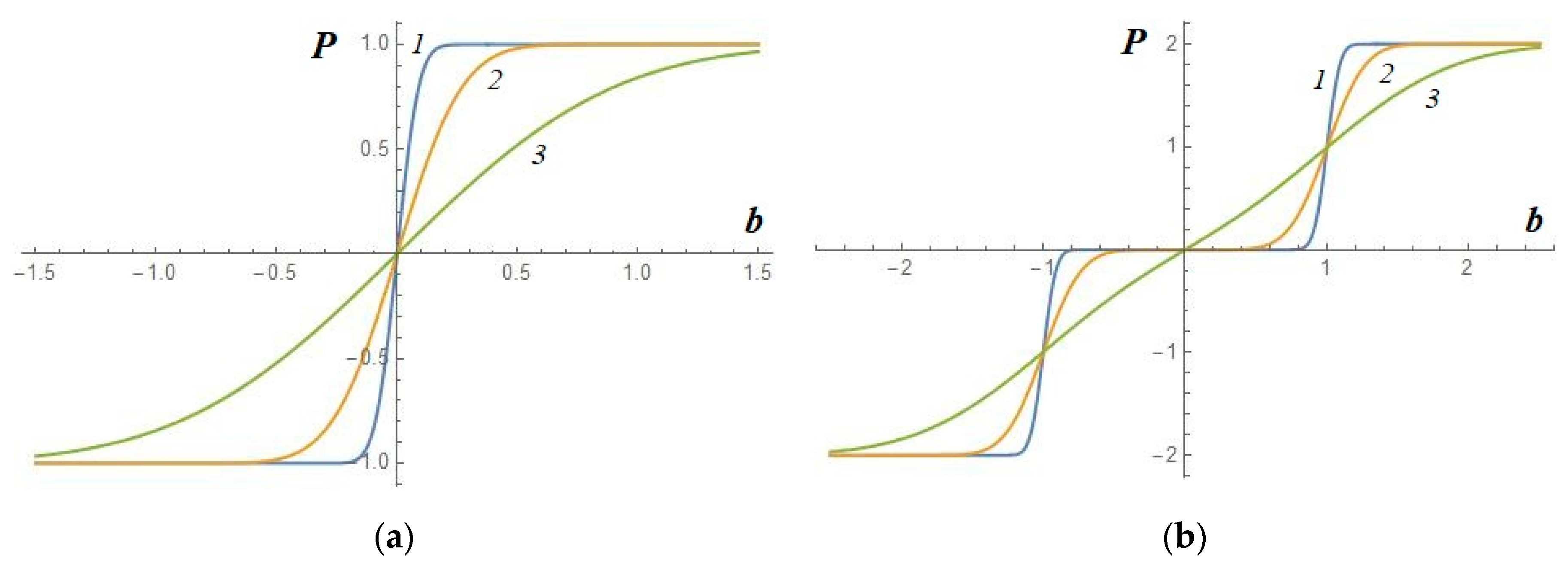
and the SFM susceptibility , where represents the susceptibility of SPMA with a vanishing inter-SPM coupling constant (i.e., ). The SFMSEs for such an uncoupled SPMA are shown in Figure 9 at values of parameter . Evidently, jumps in SPM magnetic moments give rise to stepwise anomalies in SFMSE for small numbers of a disorder . Such sharp stepwise behavior is smeared out at growing disorder.
4.2. SFM Phase Diagram
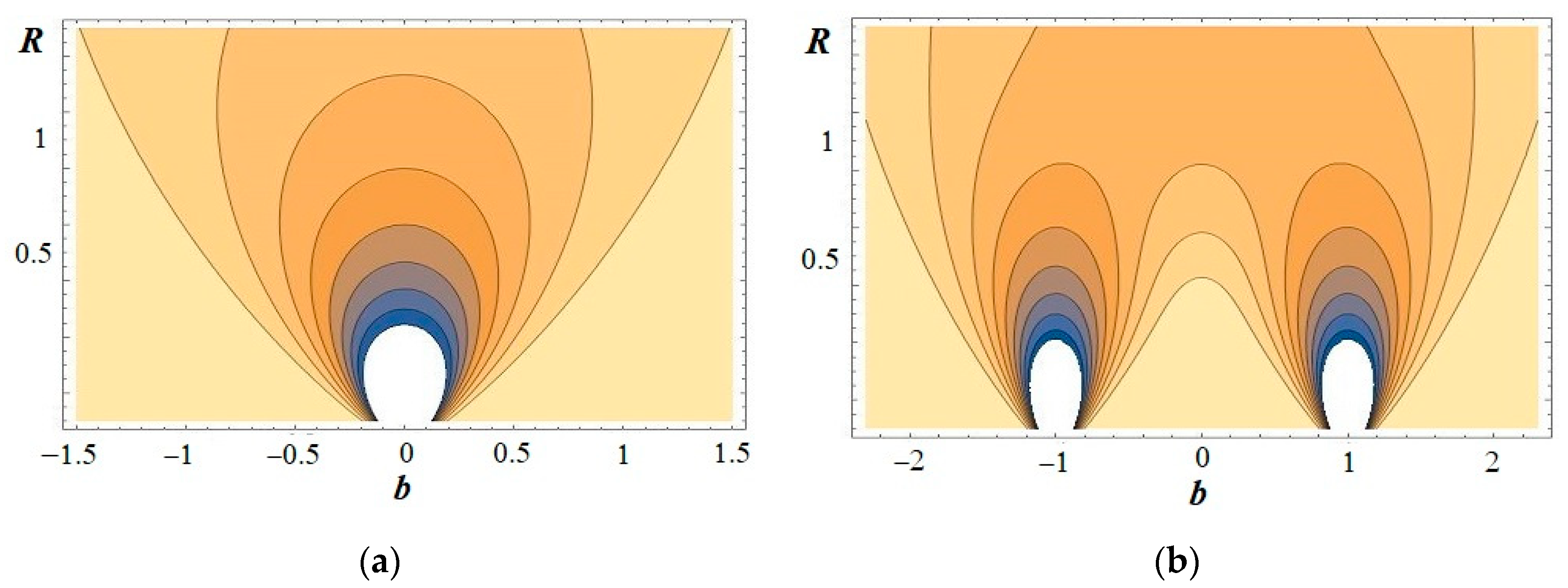
The inter-SPM coupling causes hysteresis behavior in SFM magnetic curves at field strengths matching SPM moment jump peculiarities. Such phenomena can be understood in terms of avalanche propagation through SPMA. When the local field bi associated with some i-th SPM in a lattice crosses over the critical value bn (see above), the respective SPM magnetic moment changes step-wise. Because of inter-SPM ferromagnetic interaction, a jumping SPM magnetic moment can trigger a jump of some element from the nearest neighbors, which may in turn activate some of their neighbors, and so on, creating, thereby, an SPM jump avalanche, cf., [34,35]. As a result, the SFM magnetization curve demonstrates abrupt stepwise behavior. Employing the mean-field approximation (see Equations (20) and (22)), SFMSE is reduced to the equality . The single jump of SPM particle magnetic moment triggers average stimulated break-jumping SPMs. Therefore, the negative susceptibility, cf., Equation (22), determines the spinodal region for SFM. In this region, the average number of triggered SPM magnetic moment jumps exceeds 1, and SFM favors evolving in a global jump cascade. In this case, sharp magnetization dynamics cover practically all the sample, extending into a macro-SFM magnetization discontinuity. Consequently, conditions for the spinodal region correspond to the inequality . The lines of a constant susceptibility display, thereby, such instability domains in the {B, R}-plane, as is illustrated in Figure 10. The larger (right) and lower (left) field lines cross over at the point of self-organized criticality. As is indicated in Figure 10b, for a case of two brake-jumps of SPM magnetic moments, SFM with a small interparticle interaction strength exhibits well-separated spinodal domains. Then, the respective SFM magnetic evolution resembles the case of a single SPM jump. On the contrary, the strong coupling strength results in a wide instability region, while limited isolated stability areas, obviously, arise at small disorder parameters R.
4.3. SFM Dynamics and Analytical Tools to Reveal SFM Structure
As is illustrated by the description within the mean field approach (see Section 4.1 and Section 4.2) the magnetodynamics of SFM systems display spinodal regions of unstable behavior at small disorder parameters R and show a stable character of evolution at considerable numbers . The spinodal regions give rise to significant hysteresis effects at instability domains. The intermediate dynamical regime is met at a critical point associated with the SOC neighborhood. The SOC vicinity can be quantified by value d, defined as a difference from one of the mean numbers of triggered jumps, i.e., (see Section 4.1 and Section 4.2). At such SOC conditions, the average number of induced SPM jumps approaches 1, and the length of the average largest avalanche is given as of the SFM linear size. Correspondingly, the avalanche (noise) size distribution can be written as [34]
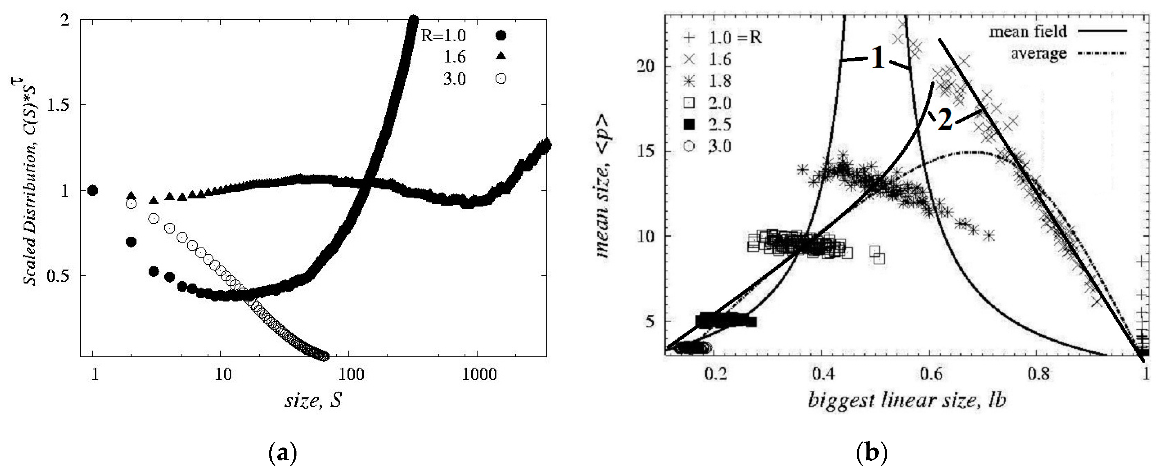
In the modeling of the SFM magnetodynamics, we use SPMA containing (30)3 SPM particles arranged in a simple cubic lattice. Employing the cumulative size distributions with their respective differential values D(S) allows for reduced statistical uncertainties in the processing and examination of the avalanche size distribution. Inclusive values C(S) collected from over 100 events of the SFM magnetization reversals are illustrated in Figure 4a. In the case of small disorders—below the critical point—one clearly sees the ‘U’-shaped form of the size composition C(S). At increasing R, the shape of the size composition becomes a sharp exponential decrease with noticeable size cascades. At values approaching the critical number, the distribution shows the power law shape with an exponent , i.e., an exponent of 1.85 for the differential distribution , and is very close to an estimate within the mean-field approach.
Analytical tools developed in investigations of critical phenomena in atomic nuclei and clusters (see [36,37] and references therein) constitute a useful framework for the specification, qualification, quantification, and analysis of SOC in SFM magnetodynamics. Especially, we analyze avalanche size correlations as follows: For certain ith SFM magnetodynamic events, we define conditional moments,
where the sum accounts for all the avalanche sizes , excluding the biggest size. Considering Equation (8), the conditional moments in Equation (24) can be estimated as <pk>mf ~ |d|1−2k + const(d). As is seen in the SOC region, i.e., when , the moments of the ranges k = 1, 2, 3 …diverge at the thermodynamic limit . Such features can be employed as a method for quantitative determination and analysis of SOC evidence and properties, as well as of SFM structure and dynamics.
When SFMs undergo critical behavior relevant for the SOC predecessor in certain SFM evolution events, SFM magnetic discontinuities should exhibit considerable noise correlations. For instance, at SFM magnetodynamics, one can analyze correlations between the strongest SFM magnetic signal (i.e., the largest avalanche ) and the mean noise amplitude for the remaining jumps in this particular event. Such events can be obtained from simulations, observations, and/or experiments. Such correlation analyses resemble the scatter plots for liquid-gas phase transitions [34,36]. As is illustrated in Figure 11b, over- and under-critical events are clearly split as left- and right-hand side branches corresponding to small and large sizes of the largest avalanche-jump amplitude. These branches overlap at SOC conditions corresponding to the maximum of mean jump (noise) amplitude. The events located in the right-hand side branch of Figure 11b arise at small values R, while the dynamics relevant for large disorders R bring events to the left-hand side part of the plot. The mean field treatment in the thermodynamic limit reproduces only qualitatively the RJIM model results.
For a finite system from Equation (24), the mean value can be written as
As is evident from Equations (23) and (24) the total number of avalanches—moment <p0>—depends only slightly on the maximum size Sb. This feature can be clearly observed in Figure 11b. Especially at small disorders—less than the critical value—and small jump numbers <p0>, the right-hand side events in Figure 3b are mainly defined by the largest avalanche jump covering almost the whole SFM system. At considerable disorders—above the critical value—the large number <p0> gives rise to the smooth distribution D(S). Then from Equations (23) and (24) for the average avalanche size, one obtains <p> ~ [erf(d (Sb/2)½)—erf(d/2½) ] 2½/d, where erf(x) denotes the error integral. In the vicinity of the critical point, i.e., , this relation is reduced to <p> ~ Sb½. As is displayed in Figure 11b, this result is in reasonable agreement with RJIM simulations in the left-hand side part.
5. SPMA as Sensors for SPM
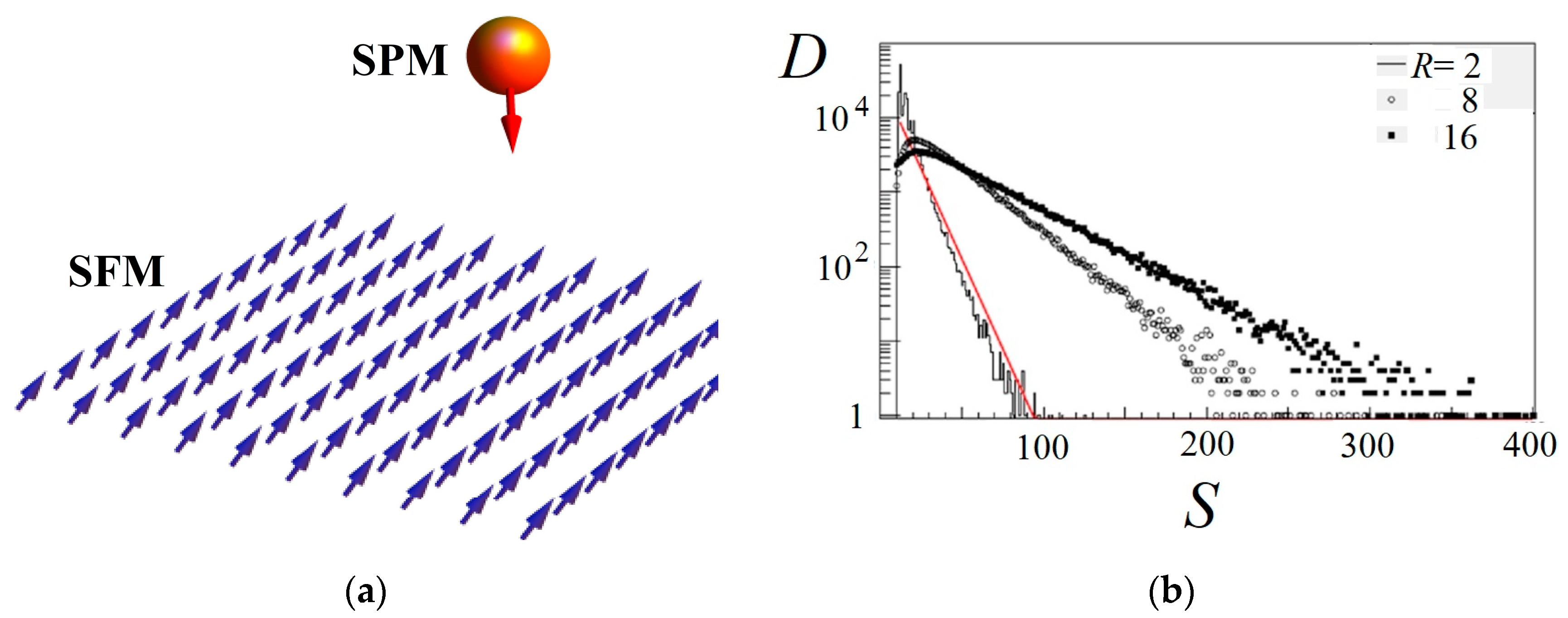
Sensors and magnetic particle imaging represent possible SPMA applications, cf., [38,39] and refs. therein. To consider the potential implications of practical SFM systems as MR sensors for tracking down, e.g., a single magnetic particle (see Figure 12a), we examine how the spatially local magnetic field triggers jumps of a couple SPMA components [35]. These local perturbations induce an avalanche of SPM magnetic moment jumps because of ferromagnetic interaction, and the GMR amplitude is commensurate with the number S of SFM elements in an avalanche.
We model the magnetodynamics for SFM of a simple quadric planar lattice with a square size of (1000)2 elements. The local magnetic shock fields are randomly distributed in a plane, creating local avalanches of SPM jumps. As is shown in Figure 12b, the avalanche size distribution D(S) exhibits a nearly exponential shape with a gentler slope for larger disorder parameters R. Such a feature can be understood within the mean-field approach. Since the mean-field approximation implies that the mean number of jumping SPM moments triggered by a single jumping seed is spatially independent, the avalanche size distribution at 1 << S << Π is given by Equation (23). For increasing disorder parameter R in the considered range, the value d decreases. Consequently, the exponential slant of D(S) reduces in conjunction with Equation (23). As a result, more intensive MR signals from a sensor are expected for larger disorders. However, the detection is less sensitive spatially in this case.
6. Discussion
We discussed magnetism in nanocrystals of strong ferromagnets and their arrays. At subdomain spatial size, such nanoparticles can be treated as superparamagnets (SPMs). It has been shown that the band-structure-based shell (BSBSh) model provides a realistic description of the size-dependent magnetic properties of transition metal nanocrystals. In particular, this picture reproduces quite well the size dependence of the SPM magnetic moment. It is worth noticing that similar properties of magnetized atomic nuclei are important for understanding magnetar ultramagnetized neutron star activity [40] and explosive nucleosynthesis [41].
As shown, the SPM arrays (and/or ensembles) (SPMAs) demonstrate superferromagnetic ordering at sufficiently large SPM densities. This behavior originates from direct and/or indirect exchange coupling between SPMs in insulators, semiconductors, and/or conducting substrates. The magnetodynamics of SPM assemblies (SPMAs) were investigated within a randomly jumping interacting moments (RJIM) model accounting for superferromagnetic (SFM) and discrete SPM structure effects. The SPMA magnetic evolution is demonstrated to exhibit sharp, jerky ruptures in magnetization curves. As is shown within the men-field approach, the SFM state equation implies an unstable magnetic behavior. Respectively, spinodal areas and points of self-organized criticality (SOC) are displayed on {magnetic field, disorder} plane for the SFM phase diagram. We introduced analytical tools to define, quantify, specify, and describe the structure and origin of SFMs and SOCs. The tools explore correlations of noise amplitudes in magnetodynamics. Additional magnetic response anomalies and new phases are argued to arise due to quantum fluctuations originated in the SPM discrete-level structure.
The giant and tunnel magnetoresistance effects are clearly justified to grow for SPMs of smaller sizes abutted by conducting or non-conducting materials. Such a property, in conjunction with SPMA magnetodynamical features, is quite appropriate for magnetoresistive sensors. Increased area of SPM moment jumps induced by a local field in SPMAs due to quenched disorder leads to an enhanced magnetoresistive signal and the detection sensitivity at considered parameters. In addition, new SPMA phases could provide additional prospects for sensor implementations. Such developments are of considerable significance for advanced nanoscale electronic and memory devices, biology, and advanced therapy.
7. Conclusions
We analyzed the possibilities of applications of superparamagnet assemblies (SPMA) for magnetoresistive (MR) sensors (MRS). At sufficiently closed SPM packing, such SPMAs display superferromagnetic (SFM) ordering. As is demonstrated, such a property is favorable for MRS implications due to the proper positional sensitivity of the spatially local SFM magnetic response and the considerable MR effect for SPMs. The MR effect is argued to grow for tunnel current between SPMs with decreasing SPM sizes because of enhanced level density. We also find suitable conditions for giant MR between SPMs on conducting substrates. Although at disorders in SPMAs the MR spatial resolution is reduced, the MR signal grows.
In addition, disorder effects in SPMAs lead to an occurrence of self-organized criticality (SOC) that represents a particularly interesting phenomenon met in many branches of nature, cf., [42,43] and refs. therein. We employ model-independent analytical tools for quantitative specification and investigation of SPMA magnetodynamics in relation to SOC conditions. Such an instrument explores magnetic noise correlations in SPMA dynamics and, in particular, mean versus strongest noise amplitude. Such an approach allows one to identify and investigate the SOC point.
Author Contributions
Conceptualization, V.N.K. and V.A.O.; methodology, V.N.K. and V.A.O.; software, V.N.K.; validation, V.N.K. and V.A.O.; formal analysis, V.N.K. and V.A.O.; investigation, V.N.K. and V.A.O.; data curation, V.N.K. and V.A.O.; writing—original draft preparation, V.N.K. and V.A.O.; writing—review and editing, V.N.K. and V.A.O.; visualization, V.N.K. and V.A.O.; supervision, V.A.O. All authors have read and agreed to the published version of the manuscript.
Funding
This research received no external funding.
Informed Consent Statement
Not applicable.
Data Availability Statement
Not applicable.
Conflicts of Interest
The authors declare no conflict of interest.
References
- Reiss, G.; Brueckl, H.; Huetten, A.; Schotter, J.; Brzeska, M.; Panhorst, M.; Sudfeld, D.; Becker, A.; Kamp, P.B.; Puehler, A.; et al. Magnetoresistive sensors and magnetic nanoparticles for biotechnology. J. Mater. Res. 2005, 20, 3294–3302. [Google Scholar] [CrossRef]
- Ennen, I.; Kappe, D.; Rempel, T.; Glenske, C.; Hütten, A. Giant magnetoresistance: Basic concepts, microstructure, magnetic interactions and applications. Sensors 2016, 16, 904. [Google Scholar] [CrossRef]
- Matus, M.F.; Häkkinen, H. Understanding ligand-protected noble metal nanoclusters at work. Nat. Rev. Mater. 2023, 8, 372–389. [Google Scholar] [CrossRef]
- Chuanbo, G.; Fenglei, L.; Yadong, Y. Encapsulated Metal Nanoparticles for Catalysis. Chem. Rev. 2021, 121, 834–881. [Google Scholar]
- Bedanta, S.; Wolfgang, K. Supermagnetism. J. Phys. D Appl. Phys. 2008, 42, 013001. [Google Scholar] [CrossRef]
- Dormann, J.-L.; Fiorani, D.; Tronc, E. Magnetic relaxation in fine-particle systems. Adv. Chem. Phys. 1997, 98, 283–494. [Google Scholar]
- Heinrich, B.; Bland, J.A.C. (Eds.) Ultrathin Magnetic Structures; Springer: Berlin/Heidelberg, Germany, 1994. [Google Scholar]
- Wijn, H.P.J. (Ed.) Magnetic Properties of Metals; Springer: Berlin/Heidelberg, Germany, 1991. [Google Scholar]
- Kondratyev, V.N.; Lutz, H.O. Shell effect in exchange coupling of transition metal dots and their arrays. Phys. Rev. Lett. 1998, 81, 4508–4511. [Google Scholar] [CrossRef]
- Kondratyev, V.N.; Lutz, H.O. Interdot Exchange Coupling in Superferromagnetism. Eur. Phys. J. D 1999, 9, 483–485. [Google Scholar] [CrossRef]
- Brack, M.; Bhaduri, R.K. Semiclassical Physics; Addison-Wesley: Reading, MA, USA, 1997. [Google Scholar]
- Reimann, S.M.; Persson, M.; Lindelof, P.E.; Brack, M. Shell structure of a circular quantum dot in weak magnetic field. Z. Phys. B 1996, 101, 377. [Google Scholar] [CrossRef]
- Reimann, S.M.; Manninen, M. Electronic structure of quantum dots. Rev. Mod. Phys. 2002, 74, 1283. [Google Scholar] [CrossRef]
- Kondratyev, V.N. Multipole Moments of Electronic Vacancies Produced by Fast Particles in Atomic Clusters. Phys. Lett. A 1993, 179, 209–213. [Google Scholar] [CrossRef]
- Kondratyev, V.N. Strong Valence Electron Excitation due to Internal Conversion or K-capture. Phys. Lett. A 1994, 190, 465–468. [Google Scholar] [CrossRef]
- Apsel, S.E.; Emmert, J.W.; Deng, J.; Bloomfield, L.A. Surface-enhanced magnetism in nickel clusters. Phys. Rev. Lett. 1996, 76, 1441. [Google Scholar] [CrossRef]
- Billas, I.M.L.; Becker, J.A.; Chatelain, A.; de Heer, W.A. Magnetic moments of iron clusters with 25 to 700 atoms and their dependence on temperature. Phys. Rev. Lett. 1993, 71, 4067. [Google Scholar] [CrossRef]
- Billas, I.M.L.; Chatelain, A.; de Heer, W.A. Magnetism from the atom to the bulk in iron, cobalt, and nickel clusters. Science 1994, 265, 1682. [Google Scholar] [CrossRef] [PubMed]
- van Staveren, M.P.J.; Brom, H.B.; de Jongh, L.J. Metal-cluster compounds and universal features of the hopping conductivity of solids. Phys. Rep. 1991, 208, 1–96. [Google Scholar] [CrossRef]
- Slonczewski, J.C. Conductance and exchange coupling of two ferromagnets separated by a tunneling barrier. Phys. Rev. B 1989, 39, 6995. [Google Scholar] [CrossRef]
- Julliere, M. Tunneling between ferromagnetic films. Phys. Lett. A 1975, 54, 225–226. [Google Scholar] [CrossRef]
- Meservey, R.; Tedrow, P.M. Spin-polarized electron tunneling. Phys. Rep. 1994, 238, 173. [Google Scholar] [CrossRef]
- Dormann, J.; Cherkaoui, R.; Spinu, L.; Noguès, M.; Lucari, F.; D’Orazio, F.; Fiorani, D.; García-Santiago, A.; Tronc, E.; Jolivet, J. From pure superparamagnetic regime to glass collective state of magnetic moments in γ-Fe2O3 nanoparticle assemblies. J. Magn. Magn. Mater. 1998, 187, L139–L144. [Google Scholar] [CrossRef]
- Pertsev, N.A.; Tagantsev, A.K.; Setter, N. Phase transitions and strain-induced ferroelectricity in SrTiO3 epitaxial thin films. Phys. Rev. B 2000, 61, R825. [Google Scholar] [CrossRef]
- Cador, O.; Grasset, F.; Haneda, H.; Etourneau, J. Memory effect and super-spin-glass ordering in an aggregated nanoparticle sample. J. Magn. Magn. Mater. 2004, 268, 232–236. [Google Scholar] [CrossRef]
- Baibich, M.N.; Broto, J.M.; Fert, A.; van Dau, F.N.; Petro, F.; Eitenne, P.; Creuzet, G.; Friederich, A.; Chazelas, J. Giant Magnetoresistance of (001)Fe/(001)Cr Magnetic Superlattices. Phys. Rev. Lett. 1988, 61, 2472. [Google Scholar] [CrossRef]
- Binasch, G.; Grünberg, P.; Saurenbach, F.; Zinn, W. Enhanced magnetoresistance in layered magnetic structures with antiferromagnetic interlayer exchange. Phys. Rev. B 1989, 39, 4828–4830. [Google Scholar] [CrossRef]
- Berkowitz, A.E.; Mitchell, J.R.; Carey, M.J.; Young, A.P.; Zhang, S.; Spada, F.E.; Parker, F.T.; Hutten, A.; Thomas, G. Giant magnetoresistance in heterogeneous Cu-Co alloys. Phys. Rev. Lett. 1992, 68, 3745. [Google Scholar] [CrossRef] [PubMed]
- Meyer, J.; Rempel, T.; Schaefers, M.; Wittbracht, F.; Mueller, C.; Patel, A.V.; Huetten, A. Giant magnetoresistance effects in gel-like matrices. Smart Mater. Struct. 2013, 22, 025032. [Google Scholar] [CrossRef]
- Kochetov, E.A.; Osipov, V.A.; Pincak, R. Electronic properties of disclinated flexible membrane beyond the inextensional limit: Application to graphene. J. Phys. Condens. Matter 2010, 22, 395502. [Google Scholar] [CrossRef]
- Landau, L.D.; Lifshitz, E.M. Statistical Physics; Pergamon Press: Tarrytown, NY, USA, 1977; Volume 5. [Google Scholar]
- Landau, L.D.; Lifshitz, E.M. Quantum Mechanics; Pergamon Press: Tarrytown, NY, USA, 1977; Volume 3. [Google Scholar]
- Barman, A.; Mondal, S.; Sahoo, S.; De, A. Magnetization dynamics of nanoscale magnetic materials: A perspective. J. Appl. Phys. 2020, 128, 170901. [Google Scholar] [CrossRef]
- Kondratyev, V.N. Dynamics of magnetic nanoparticle assembly. J. Phys. CS 2010, 248, 012027. [Google Scholar]
- Kondratyev, V.N.; Krylov, V.V.; Bezshyyko, O.A.; Golinka-Bezshyyko, L.O.; Osipov, V.A. Response of magnetic nanoparticle assemblies. J. Phys. CS 2012, 393, 012005. [Google Scholar] [CrossRef]
- Kondratyev, V.N.; Lutz, H.O.; Ayik, S. Critical Evolution of Hot van der Waals Droplets. J. Chem. Phys. 1997, 106, 7766. [Google Scholar] [CrossRef]
- Kondratyev, V.N. Mean versus strongest signals for self-organized criticality in magnetic quantum dot arrays. Phys. Lett. A 2006, 354, 217. [Google Scholar] [CrossRef]
- Tay, Z.W.; Savliwala, S.; Hensley, D.W.; Fung, K.L.B.; Colson, C.; Fellows, B.D.; Zhou, X.; Huynh, Q.; Lu, Y.; Zheng, B.; et al. Superferromagnetic Nanoparticles Enable Order-of-Magnitude Resolution & Sensitivity Gain in Magnetic Particle Imaging. Small Methods 2021, 5, 2100796. [Google Scholar]
- Bui, T.Q.; Biacchi, A.J.; Dennis, C.L.; Tew, W.L.; Walker, A.R.H.; Woods, S.I. Advanced characterization of magnetization dynamics in iron oxide magnetic nanoparticle tracers. Appl. Phys. Lett. 2022, 120, 012407. [Google Scholar] [CrossRef] [PubMed]
- Kondratyev, V.N. Magnetoemission of Magnetars. Phys. Part. Nucl. 2019, 50, 613. [Google Scholar] [CrossRef]
- Kondratyev, V.N. R-process with magnetized nuclei at dynamo-explosive supernovae and neutron star mergers. Universe 2021, 7, 487. [Google Scholar] [CrossRef]
- Blanchard, P.; Brüning, E. Mathematical Methods in Physics; Springer: Berlin/Heidelberg, Germany, 2015. [Google Scholar]
- Sornette, A. Critical Phenomena in Natural Sciences; Springer: Berlin/Heidelberg, Germany, 2006. [Google Scholar]
Figure 1.
The density of states (DOS), ρ(E), in a ferromagnetic system that is split into majority and minority bands due to the exchange interaction. Wavy lines indicate DOS modifications due to the finite size effect.
Figure 1.
The density of states (DOS), ρ(E), in a ferromagnetic system that is split into majority and minority bands due to the exchange interaction. Wavy lines indicate DOS modifications due to the finite size effect.

Figure 2.
The magnetic moment of free SPMs presented per atom in units of the Bohr magneton μB as a function of number of atoms N. The parameters of (a) Ni—nbulks = 0.62, [bulk:surf:curv] = [1:3.1:1.0] and (b) Co—nbulks = 0.7, [bulk:surf:curv] = [1:3.1:2.1]. The solid lines represent the results of the BSBSh model at a self-field H = 0.7 T (a) and H = 1.9 T (b). The dashed lines correspond to zero self-field. The results are compared to the experimental data according to ref. [9]. In panel a the size of error bars is indicated in the left upper corner.

Figure 3.
(a) SPMA structure for insulator substrate. (b) Temperature dependence of inter-SPM coupling strength J.
Figure 3.
(a) SPMA structure for insulator substrate. (b) Temperature dependence of inter-SPM coupling strength J.

Figure 4.
The SPM electronic structure factor JD in the superexchange coupling strength for SPMA from (a) nickel and (b) cobalt. The positive JD > 0 and negative (<0) values are associated with antiferro- and ferro-magnetic ordering.
Figure 4.
The SPM electronic structure factor JD in the superexchange coupling strength for SPMA from (a) nickel and (b) cobalt. The positive JD > 0 and negative (<0) values are associated with antiferro- and ferro-magnetic ordering.

Figure 5.
Tunnel spin polarized transport between FM and/or SPM (compare to Figure 1) with (a) parallel and (b) anti-parallel orientations. The vertical lines in the middle of panels indicate the barriers on the non-conducting substrate. Slanted lines with arrows at the edges indicate the spin projection conservation under the tunnel current.

Figure 6.
TMR dependence on the number of atoms N in SPM for Ni (dashed line) and Co (solid line). This plot represents smoothed TMR without shell effect.
Figure 6.
TMR dependence on the number of atoms N in SPM for Ni (dashed line) and Co (solid line). This plot represents smoothed TMR without shell effect.

Figure 7.
Schematic view of LLL diabetic |i> (dotted lines) and adiabatic (solid lines) terms near the intersection point for zero (a) and finite (b) electric fields.
Figure 7.
Schematic view of LLL diabetic |i> (dotted lines) and adiabatic (solid lines) terms near the intersection point for zero (a) and finite (b) electric fields.

Figure 8.
Dependence of GMR on the parameter ξ. The orthogonal, unitary, and simplectic ensembles are indicated by dotted, dashed, and solid lines.
Figure 8.
Dependence of GMR on the parameter ξ. The orthogonal, unitary, and simplectic ensembles are indicated by dotted, dashed, and solid lines.

Figure 9.
State equation of SPMA constructed from particles with single (a) and two (b) magnetic jump anomalies. The curves 1, 2, and 3 are related to disorder parameters R = 0.1, 0.3, and 1 in units of interaction strength J.
Figure 9.
State equation of SPMA constructed from particles with single (a) and two (b) magnetic jump anomalies. The curves 1, 2, and 3 are related to disorder parameters R = 0.1, 0.3, and 1 in units of interaction strength J.

Figure 10.
The susceptibility of uncoupled SPMA versus local filed b and disorder R. (a) single and (b) two SPM discontinuities.
Figure 10.
The susceptibility of uncoupled SPMA versus local filed b and disorder R. (a) single and (b) two SPM discontinuities.

Figure 11.
(a) The cumulative avalanche size distribution normalized by power law with an exponent . The data are generated by RJIM model simulations of SPMA in 3-D cubic lattice of the edge length 30 at disorders R = 1-solid circles, 1.6-solid triangles, and 3-open circles. (b) The mean avalanche size versus the linear size of the largest avalanche in units of SPMA length. Dots represent the data from RJIM simulations at various values of parameter R. Dashed-dotted line joins the mean values for each disorder. Solid lines display predictions of a mean-field approach in the thermodynamic limit (lines 1) and accounting for finiteness of SPMA (lines 2).

Figure 12.
(a) Schematic view of SFM sensor mode. (b) Size distribution of avalanches triggered in sensor mode by local magnetic fields arranged randomly in the (1000)2 matrix plane at 2 × 10⁵ positions (see text). Various disorders are indicated as R = 2 (line), 8 (open circles), and 16 (solid circles). Solid line corresponds to the results given by Equation (23).

Disclaimer/Publisher’s Note: The statements, opinions and data contained in all publications are solely those of the individual author(s) and contributor(s) and not of MDPI and/or the editor(s). MDPI and/or the editor(s) disclaim responsibility for any injury to people or property resulting from any ideas, methods, instructions or products referred to in the content. |
© 2023 by the authors. Licensee MDPI, Basel, Switzerland. This article is an open access article distributed under the terms and conditions of the Creative Commons Attribution (CC BY) license (https://creativecommons.org/licenses/by/4.0/).
Share and Cite
MDPI and ACS Style
Kondratyev, V.N.; Osipov, V.A. Superferromagnetic Sensors. Nanomanufacturing 2023, 3, 263-280. https://doi.org/10.3390/nanomanufacturing3030017
AMA Style
Kondratyev VN, Osipov VA. Superferromagnetic Sensors. Nanomanufacturing. 2023; 3(3):263-280. https://doi.org/10.3390/nanomanufacturing3030017
Chicago/Turabian StyleKondratyev, Vladimir N., and Vladimir A. Osipov. 2023. "Superferromagnetic Sensors" Nanomanufacturing 3, no. 3: 263-280. https://doi.org/10.3390/nanomanufacturing3030017