
Formalising Autonomous Construction Sites with the Help of Abstract Mathematics

Abstract
:1. Introduction
- (i)
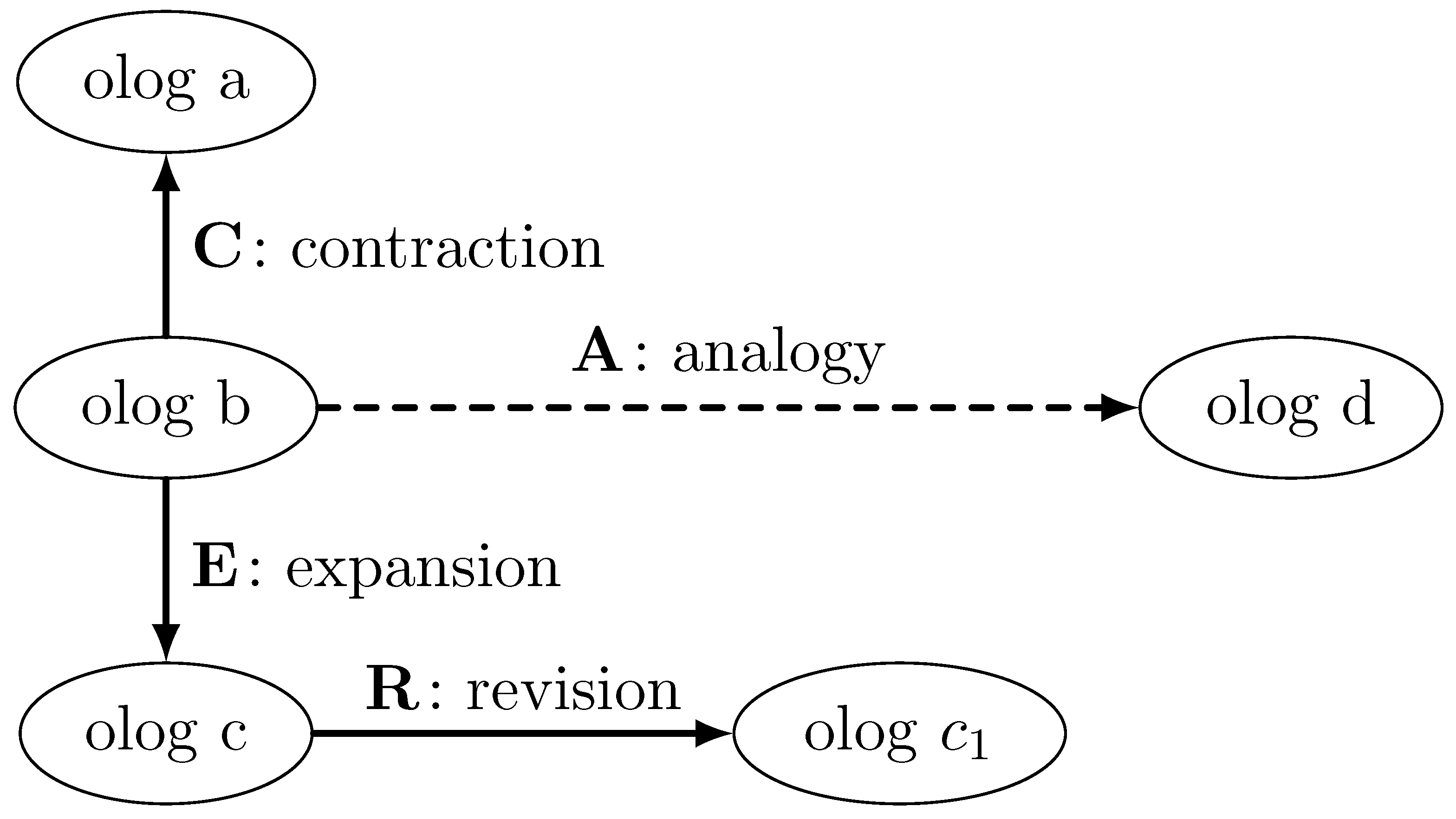
- Ologs follow the ideas of “lattice of theories” presented in [24], implying, simply speaking, that the same system can be represented by ologs with different levels of details, thus constituting a lattice of representations. This point of view can be adapted to the conceptual modelling of autonomous construction sites or engineering systems in general. A system could be modelled on a very general level at first and, after that, by using specific movements along the lattice, such as contraction, expansion, revision, and analogy, specific parts of the system can be “zoomed in”.
- (ii)
- The categorical foundation of ologs provides a clear formal procedure for relating two different ologs. This procedure is based on the concept of common ground, which is represented by a third olog related to the two other ologs. Practically, it implies that different ologs can be created for individual parts of an engineering system and then coupled together in one system of ologs.
2. Fundamentals of Category Theory and Ologs
2.1. Basics of Category Theory
- (i)
- Objects:
- (ii)
- Arrows:
- (iii)
- For each arrow f, there are given objects,called the domain and codomain of f. We writeto indicate thatand.
- (iv)
- Given arrowsand, i.e., with, there is given an arrowcalled the composite of f and g.
- (v)
- For each object A, there is given an arrowcalled the identity arrow of A.
- These data are required to satisfy the following laws:and.
- (i)
- ;
- (ii)
- ;
- (iii)
- .
- That is, F respects domains and codomains, identity arrows, and composition. In other words, functors are structure-preserving mappings between categories.
2.2. Introduction to Ologs
- A type is an abstract concept represented as a box containing a singular indefinite noun phrase. Types are allowed to have compound structure, i.e., being composed of smaller units. The following boxes are types:

- Aspects are functional relationships between the types represented by labelled arrows in ologs. Consider a functional relationship called f between types X and Y, which can be denoted, then X is called the domain of definition for the aspect f, and Y is called the set of result values of f. Here are two examples of using aspects:

- Facts are commutative diagrams, i.e., graphs with some declared path equivalences, in ologs. Facts are constructed by composing several aspects and types.
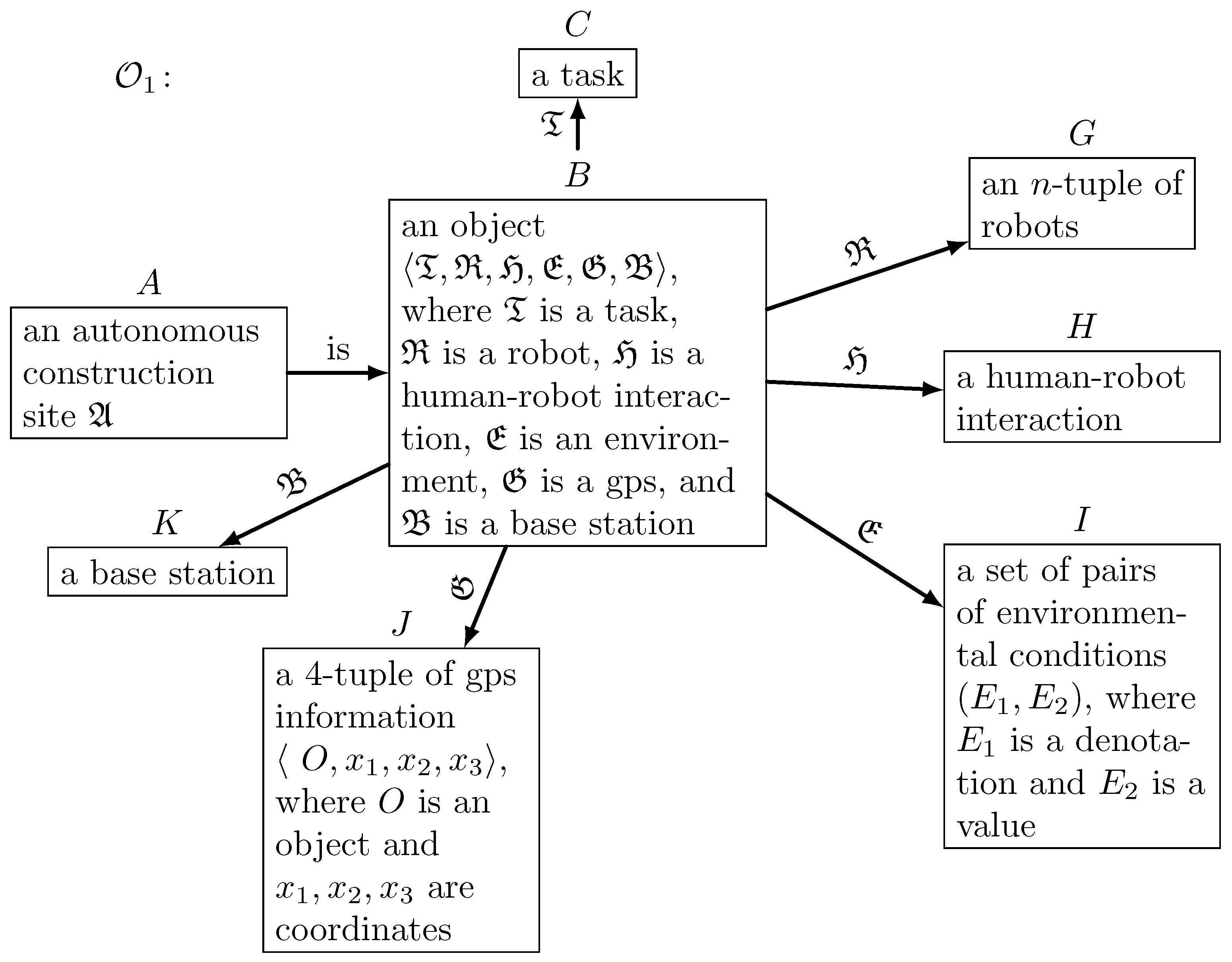
3. Abstract Description of Autonomous Construction Sites
- is a task to be solved by robots on a construction site;
- is an n-tuple of robots;
- is the object describing human–robot interaction on a construction site;
- is a set of pairs representing environmental conditions on a construction site;
- is a 4-tuple of GPS information for important parts of a construction site;
- is a base station controlling the autonomous construction site.
- The is represented by a tuple , where is a natural language sentence formulating the task, and is a formalisation of in terms of a sequence of control signals controlling cyber components of the autonomous construction site.
- The n-tuple of robots evidently contains information about all robots used on the construction site. A precise definition of a robot in the framework of the abstract approach presented in this paper is provided in Definition 5.
- Considering that autonomous construction sites naturally combine human workers and robots, it is necessary to address the question of human–robot interaction [29]. However, an abstract definition of such an interaction goes beyond the scope of the current paper. Therefore, we address the point of human–robot interaction simply by placing a specific object for it, which can still be defined later without the need to change any other definition presented in this paper.
- The role of set is to provide information about environmental conditions on a construction site. In this way, this information is formalised in terms of a denotation and the corresponding value .
- For integration of a robotic system in the construction progress, it is necessary to provide information on the positioning of the robotic system, as well as all essential parts of the construction site. For that purpose, the 4-tuple is introduced, where O denotes the object, and are object coordinates.
- Finally, cyber parts of the autonomous construction site must be controlled, and therefore, the base station needs to be included in the definition.
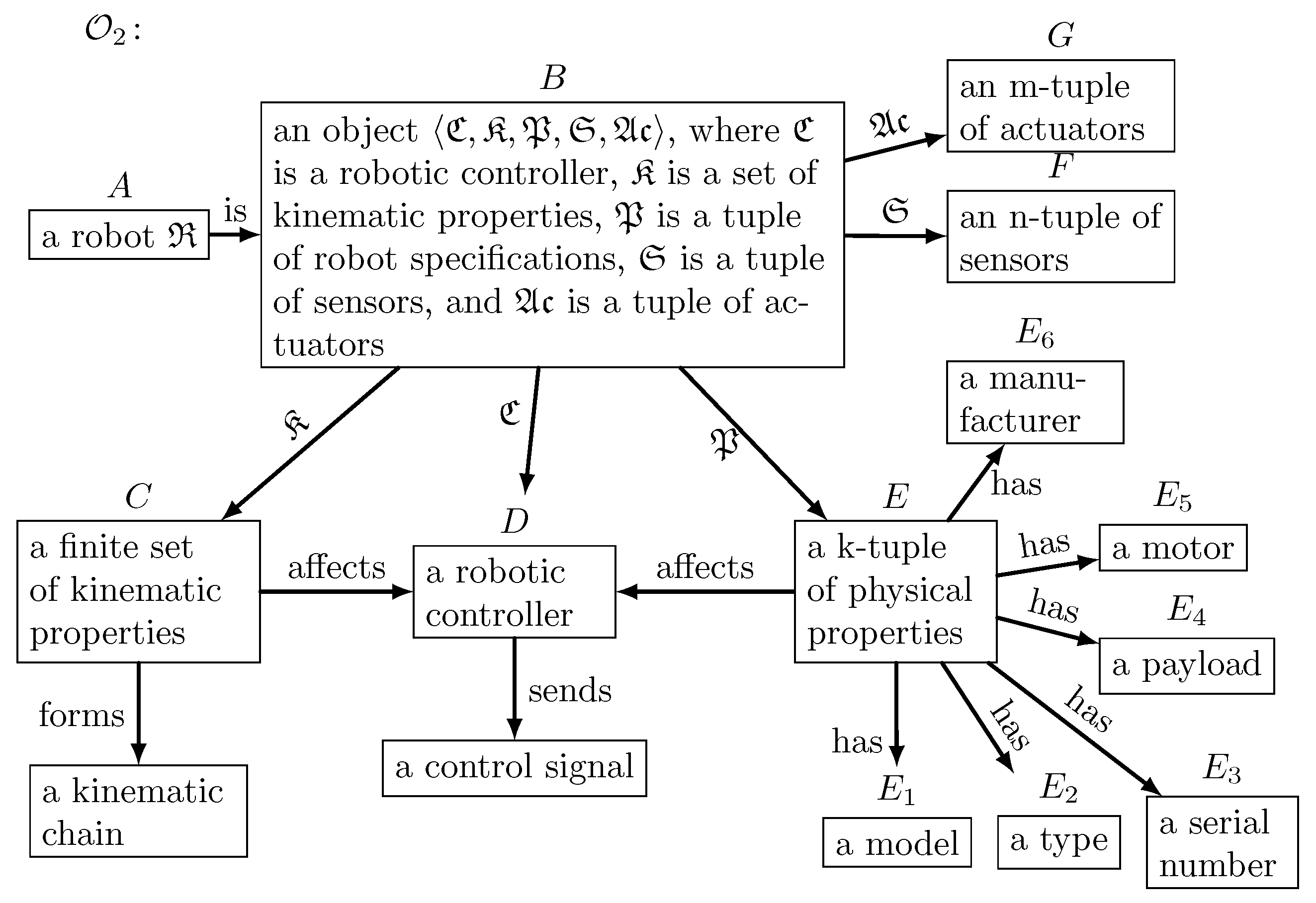
- is a robotic controller generating control signals;
- is a finite set of kinematic properties of a robot;
- is a k-tuple of physical properties of a robot;
- is an n-tuple of sensors installed on a robot;
- is an m-tuple of actuators installed on a robot.
- The robotic controller is needed for a communication with a base station introduced in Definition 4, and in general, it sends a sequence of control signals for operating the robot.
- A set of kinematic properties represents physical constraints limiting the possible movements of a robot. In practice, is determined by the kinematic chain that is formed by the series of manipulators, connected by joints, and may differ in specifications and movement, providing the (internal) axes of the robot. Furthermore, a robot system may consist of external axes, e.g., track systems. The degrees of freedom of the robotic system is the combination of internal and external axes determined by the kinematic chain. Based on the kinematic properties representing specific constraints, the robotic controller is able to generate control signals for the robot to reach target coordinates in the determined work area. Additionally, it is important to notice that for making consistent from the point of view of set theory, it is assumed that all kinematic constraints are formalised in terms of equations and inequalities, i.e., mathematical expressions.
- The tuple contains robot specification information (e.g., type, manufacturer, or information about a motor driving the system), which includes information. Physical properties have to be also known for generating control signals by the robotic controller .
- Evidently, various sensors might be installed on a robot for measuring environmental conditions, as well as important physical quantities of a robot itself, e.g., the temperature of individual parts. These sensors are combined in an n-tuple .
- Similar to sensors, various actuators need to be installed on a robot and are activated via control signals. These actuators are combined an m-tuple .
- is an n-tuple of finite index sets;
- is an n-tuple of measurements with,;
- is a k-tuple of specifications (type information).
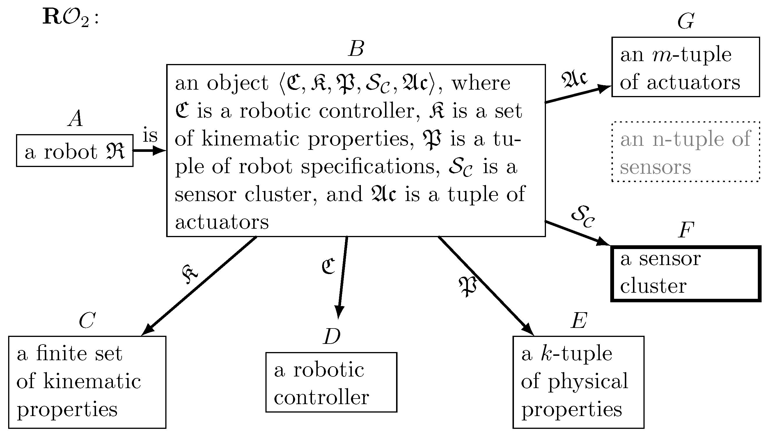
- is a sensor node or a base station controlling the sensor cluster;
- is an n-tuple of sensors, introduced in Definition 6;
- is an m-tuple of relations.
- is a sensor node or a base station controlling the actuator;
- is an actuation signal;
- is an k-tuple of specifications (typing information).
4. Olog Representations of Robotic Construction Sites

- where the dashed arrow indicates that we cannot arrive at olog from the olog in one step, and a combination of contractions and expansions is required. Hence, we obtain a lattice of representations containing several ologs that are convertible between each other and represent different levels of details about an autonomous construction site.
- (i)
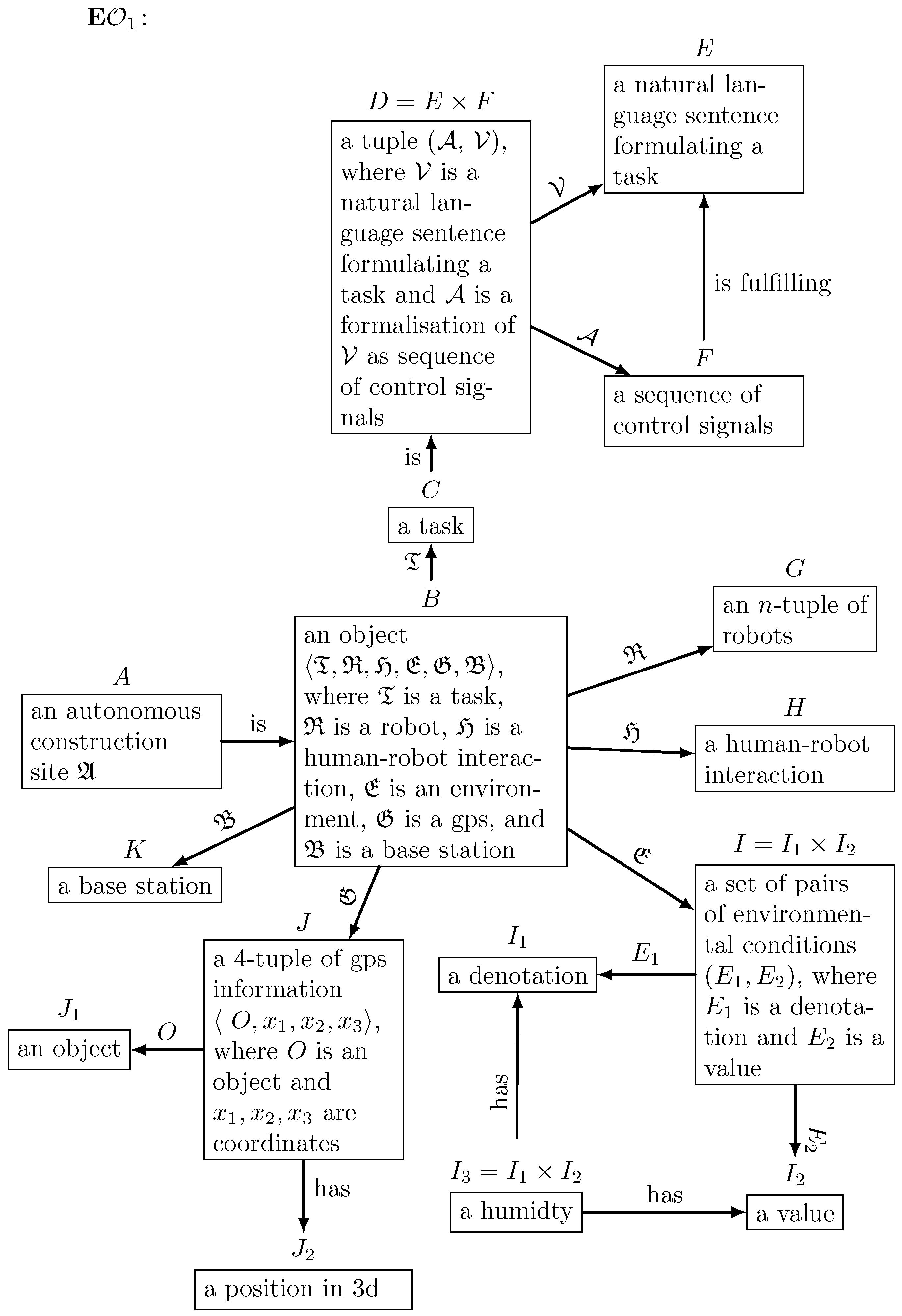
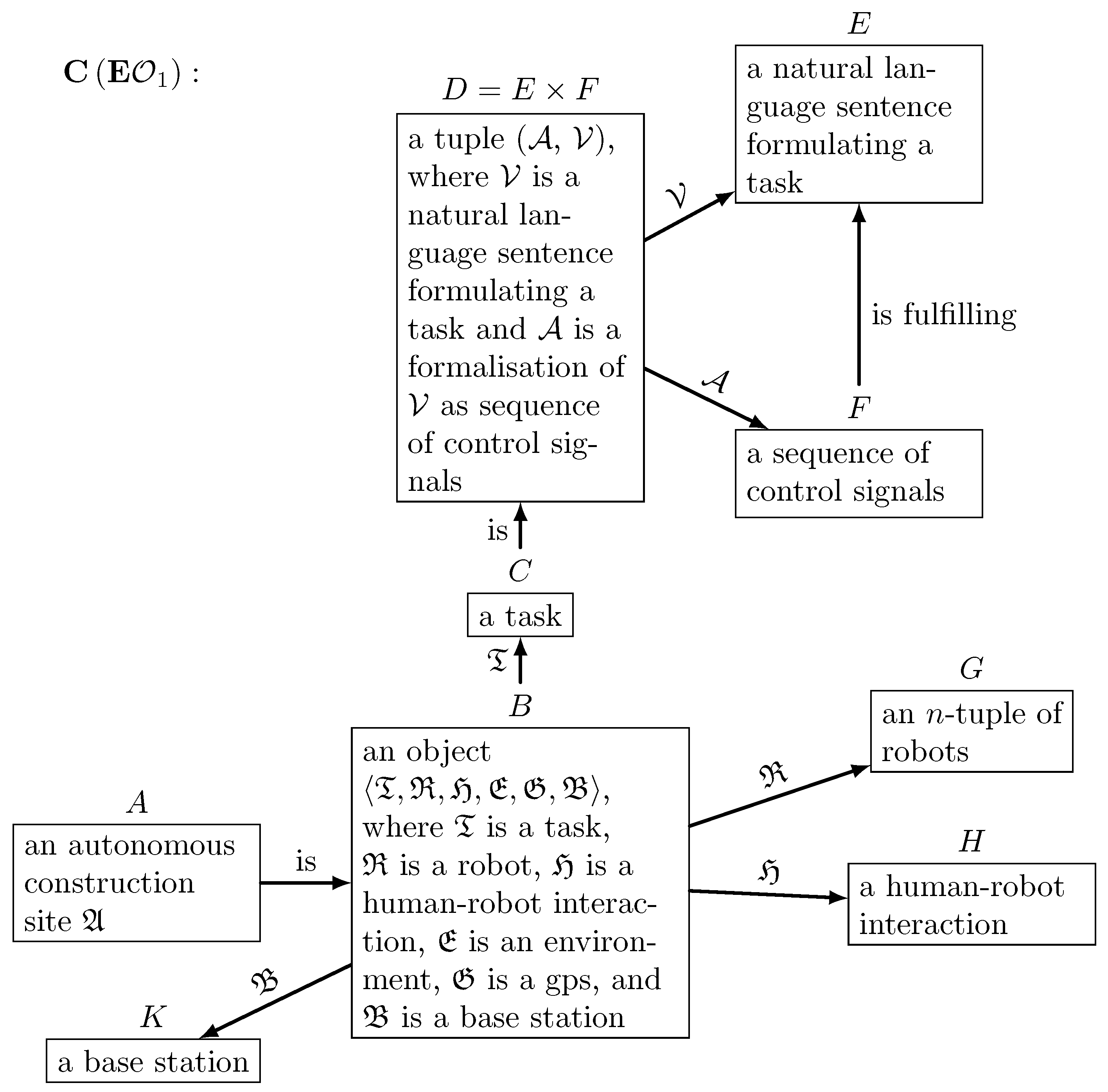
- Olog can be expanded to include olog as a sub-part.
- (ii)
- Olog can be expanded to include olog , and then the resulting olog should be contracted to olog .
- denotes the olog obtained by expanding the autonomous construction site olog by adding the robot olog to it;
- denotes the olog obtained by expanding the olog by adding the sensor olog to it;
- denotes the olog obtained by expanding the olog by adding the actuator olog to it.

- (i)
- The resulting ontological description can be easily extended by adding new definitions and ologs without a need for changing previous results;
- (ii)
- The lattice of representation can even be created at first, serving as a guideline for creating ologs and definitions;
- (iii)
- Each olog can be directly converted into a database, see again [23], and, thus, used as a basis for practical implementations of ontologies and formal representations.

5. Discussion and Conclusions
- Abstract description of autonomous construction sitesSeveral abstract definitions formalising autonomous construction sites have been introduced in Section 3. The idea of these definitions is to provide a common ground for an olog-based description of autonomous construction. A top-to-bottom approach for conceptual modelling of autonomous construction sites has been chosen. Hence, starting with an autonomous construction site, definitions of its more detailed components have been added step-by-step. The main advantage of this approach is that the resulting conceptual modelling framework is scaleable and extendable with more details, if necessary. Any of the Definitions 4–8 can be revised or updated without the need for a general restructuring of the complete framework presented in this paper.It is also important to underline that the field of robotic construction still misses generally accepted “standard” definitions. Therefore, the results presented in Section 3 should not be understood in the way of the definitions to become an industrial standard but rather as an approach on how to address practical engineering problems on a more abstract level sieving out all concrete details.
- Olog-based representations of autonomous constructionAn olog-based representation of autonomous construction sites has been presented in Section 4. As described in Section 2.2, ologs are designed to handle the subjectivism of the creator of the abstract model. This point has been further strengthened by coupling ologs with abstract definitions introduced in Section 3. This coupling makes the relation and comparison, as well as the translation of ologs, even more mathematically sound and formal. Hence, the ologs presented in this paper can be straightforwardly implemented in the form of databases, as well as the extension/contraction rules. Further, if more details are desired in a concrete application, these details can be easily added via revision of existing ologs, as has been demonstrated in the paper.
- Lattice of representationsFinally, Section 4 presents a lattice of representations, which is developed by extending and revising existing ologs. Arguably, the concept of the lattice of representations is the most powerful tool of olog-based description of engineering systems. First, the lattice can be easily extended without the need for changing previous results. In this case, a new olog is simply added to the lattice, and the corresponding extension is then formally defined. Second, the lattice of representation can even be created first and, hence, provide a guideline for creating ologs and missing definitions.
- The first step should be the formal creation of a lattice of representations, where, of course, instead of ologs, only names of important parts to be described are written. In this step, it is important to decide what should be the least detailed olog and how many different parts need to be modelled.
- Collect/create definitions of all parts to be described by ologs. In this step, it is important to keep the balance between the number of details and the level of abstractions. This balance is generally to be defined by the modeller and the objective of the work. Evidently, existing definitions, for example, industry standards, can be used, or new definitions can be developed, as has been done in this paper.
- Create ologs for each part and fit them into the lattice of representations defined in Step 1. Further, if necessary, ologs can be converted into databases and connected to other conceptual models, if available.
Author Contributions
Funding
Institutional Review Board Statement
Informed Consent Statement
Data Availability Statement
Conflicts of Interest
Abbreviations
| Olog | Ontology log |
| UAV | Unmanned aerial vehicle |
References
- Bock, T. The future of construction automation: Technological disruption and the upcoming ubiquity of robotics. Autom. Constr. 2015, 59, 113–121. [Google Scholar] [CrossRef]
- Keating, S.; Lel, J.; Cai, L.; Oxman, N. Toward site-specific and self-sufficient robotic fabrication on architectural scales. Sci. Robot. 2017, 2, eaam8986. [Google Scholar] [CrossRef] [PubMed]
- Hack, N.; Dörfler, K.; Walzer, A.N.; Wangler, T.; Mata-Falcón, J.; Kumar, N.; Buchli, J.; Kaufmann, W.; Flatt, R.J.; Gramazio, F.; et al. Structural stay-in-place formwork for robotic in situ fabrication of non-standard concrete structures: A real scale architectural demonstrator. Autom. Constr. 2020, 115, 103197. [Google Scholar] [CrossRef]
- Wagner, H.J.; Alvarez, M.; Kyjanek, O.; Bhiri, Z.; Buck, M.; Menges, A. Flexible and transportable robotic timber construction platform—TIM. Autom. Constr. 2020, 120, 103400. [Google Scholar] [CrossRef]
- Willmann, J.; Knauss, M.; Bonwetsch, T.; Apolinarska, A.A.; Gramazio, F.; Kohler, M. Robotic timber construction—Expanding additive fabrication to new dimensions. Autom. Constr. 2016, 61, 16–23. [Google Scholar] [CrossRef]
- Dörfler, K.; Sandy, T.; Giftthaler, M.; Gramazio, F.; Kohler, M.; Buchli, J. Mobile Robotic Brickwork. In Robotic Fabrication in Architecture, Art and Design 2016; Reinhardt, D., Saunders, R., Burry, J., Eds.; Springer: Cham, Switzerland, 2016; pp. 204–217. [Google Scholar]
- Lindemann, H.; Gerbers, R.; Ibrahim, S.; Dietrich, F.; Herrmann, E.; Dröder, K.; Raatz, A.; Kloft, H. Development of a Shotcrete 3D-Printing (SC3DP) Technology for Additive Manufacturing of Reinforced Freeform Concrete Structures. In First RILEM International Conference on Concrete and Digital Fabrication—Digital Concrete 2018. DC 2018. RILEM Bookseries; Wangler, T., Flatt, R., Eds.; Springer: Cham, Switzerland, 2018; Volume 19, pp. 204–217. [Google Scholar]
- Helm, V.; Willmann, J.; Gramazio, F.; Kohler, M. In-Situ Robotic Fabrication: Advanced Digital Manufacturing Beyond the Laboratory. In Gearing up and Accelerating Cross-fertilization between Academic and Industrial Robotics Research in Europe: Technology Transfer Experiments from the ECHORD Project. Springer Tracts in Advanced Robotics; Röhrbein, F., Veiga, G., Natale, C., Eds.; Springer: Cham, Switzerland, 2014; Volume 94, pp. 63–83. [Google Scholar]
- Chai, H.; Wagner, H.J.; Guo, Y.; Qi, Y.; Menges, A.; Yuan, P.F. Computational design and on-site mobile robotic construction of an adaptive reinforcement beam network for cross-laminated timber slab panels. Autom. Constr. 2022, 142, 104536. [Google Scholar] [CrossRef]
- Keitel, H.; Karaki, G.; Lahmer, T.; Nikulla, S.; Zabel, V. Evaluation of coupled partial models in structural engineering using graph theory and sensitivity analysis. Eng. Struct. 2011, 33, 3726–3736. [Google Scholar] [CrossRef]
- Dutailly, J.C. Hilbert Spaces in Modelling of Systems; 2014; 47p. Available online: https://hal.archives-ouvertes.fr/hal-00974251 (accessed on 14 August 2021).
- Dutailly, J.C. Common Structures in Scientific Theories; 2014; 34p. Available online: https://hal.archives-ouvertes.fr/hal-01003869 (accessed on 14 August 2021).
- Legatiuk, D.; Smarsly, K. An abstract approach towards modeling intelligent structural systems. In Proceedings of the 9th European Workshop on Structural Health Monitoring, Manchester, UK, 10–13 July 2018. [Google Scholar]
- Nefzi, B.; Schott, R.; Song, Y.Q.; Staples, G.S.; Tsiontsiou, E. An operator calculus approach for multi-constrained routing in wireless sensor networks. In Proceedings of the 16th ACM International Symposium on Mobile Ad Hoc Networking and Computing, New York, NY, USA, 22–25 June 2015. [Google Scholar]
- Vassilyev, S.N. Method of reduction and qualitative analysis of dynamic systems: I. J. Comput. Syst. Int. 2006, 17–25. [Google Scholar] [CrossRef]
- Vassilyev, S.N.; Davydov, A.V.; Zherlov, A.K. Intelligent control via new efficient logics. In Proceedings of the 17th World Congress The International Federation of Automatic Control, Seoul, Republic of Korea, 6–11 July 2008. [Google Scholar]
- Gürlebeck, K.; Nilsson, H.; Legatiuk, D.; Smarsly, K. Conceptual modelling: Towards detecting modelling errors in engineering applications. Math. Methods Appl. Sci. 2020, 43, 1243–1252. [Google Scholar] [CrossRef]
- Legatiuk, D.; Nilsson, H. Abstract modelling: Towards a typed declarative language for the conceptual modelling phase. In Proceedings of the 8th International Workshop on Equation-Based Object-Oriented Modeling Languages and Tools, Weßling, Germany, 1 December 2017. [Google Scholar]
- Foley, J.D.; Breiner, S.; Subrahmanian, E.; Dusel, J.M. Operands for complex system design specification, analysis and synthesis. Proc. R. Soc. 2021, 477. [Google Scholar]
- Gürlebeck, K.; Hofmann, D.; Legatiuk, D. Categorical approach to modelling and to coupling of models. Math. Methods Appl. Sci. 2017, 40, 523–534. [Google Scholar] [CrossRef]
- Kavrakov, I.; Legatiuk, D.; Gürlebeck, K.; Morgenthal, G. A categorical perspective towards aerodynamic models for aeroelastic analyses of bridges. R. Soc. Open Sci. 2019, 6, 181848. [Google Scholar] [CrossRef] [PubMed] [Green Version]
- Legatiuk, D. Mathematical modelling by help of category theory: Models and relations between them. Mathematics 2022, 9, 1946. [Google Scholar] [CrossRef]
- Spivak, D.; Kent, R. Ologs: A categorical framework for knowledge representation. PLoS ONE 2012, 7, e24274. [Google Scholar] [CrossRef] [PubMed]
- Sowa, J. Knowledge Representation: Logical, Philosophical, and Computational Foundations; Brooks/Cole: Pacific Grove, CA, USA, 2000. [Google Scholar]
- Awodey, S. Category Theory; Oxford University Press Inc.: New York, NY, USA, 2010. [Google Scholar]
- Spivak, D. Category Theory for Scientists; MIT Press: Cambridge, MA, USA, 2014. [Google Scholar]
- Haidegger, T. Taxonomy and Standards in Robotics. In Encyclopedia of Robotics; Ang, M.H., Khatib, O., Siciliano, B., Eds.; Springer: Berlin/Heidelberg, Germany, 2021. [Google Scholar]
- Lynch, K.M.; Park, F.C. Modern Robotics: Mechanics, Planning, and Control; Cambridge University Press: Cambridge, UK, 2017. [Google Scholar]
- Brosque, C.; Galbally, E.; Khatib, O.; Fischer, M. Human-Robot Collaboration in Construction: Opportunities and Challenges. In Proceedings of the 2020 International Congress on Human-Computer Interaction, Optimization and Robotic Applications (HORA), Ankara, Turkey, 26–27 June 2020; pp. 1–8. [Google Scholar]
- Christensen, O. An Introduction to Frames and Riesz Bases; Springer International Publishing: Heidelberg, Germany, 2016. [Google Scholar]
- Syarif, A.; Abouaissa, A.; Idoumghar, L.; Lorenz, P.; Schott, R.; Staples, S.G. New path centrality based on operator calculus approach for wireless sensor network deployment. IEEE Trans. Emerg. Top. Comput. 2019, 7, 162–173. [Google Scholar] [CrossRef]


Disclaimer/Publisher’s Note: The statements, opinions and data contained in all publications are solely those of the individual author(s) and contributor(s) and not of MDPI and/or the editor(s). MDPI and/or the editor(s) disclaim responsibility for any injury to people or property resulting from any ideas, methods, instructions or products referred to in the content. |
© 2023 by the authors. Licensee MDPI, Basel, Switzerland. This article is an open access article distributed under the terms and conditions of the Creative Commons Attribution (CC BY) license (https://creativecommons.org/licenses/by/4.0/).
Share and Cite
Legatiuk, D.; Luckey, D. Formalising Autonomous Construction Sites with the Help of Abstract Mathematics. Eng 2023, 4, 799-815. https://doi.org/10.3390/eng4010048
Legatiuk D, Luckey D. Formalising Autonomous Construction Sites with the Help of Abstract Mathematics. Eng. 2023; 4(1):799-815. https://doi.org/10.3390/eng4010048
Chicago/Turabian StyleLegatiuk, Dmitrii, and Daniel Luckey. 2023. "Formalising Autonomous Construction Sites with the Help of Abstract Mathematics" Eng 4, no. 1: 799-815. https://doi.org/10.3390/eng4010048