1. Introduction
A key aspect for the adoption of electromobility is the improvement of the convenience in the charging of electric vehicles (EVs). In this regard, wireless power transfer systems (WPTSs) provide a very user-friendly charging technology by wirelessly transferring power from an offboard ground pad module (GPM) to an onboard car pad module (CPM) without the need for manual intervention. The setup of an exemplary WPTS is illustrated in
Figure 1.
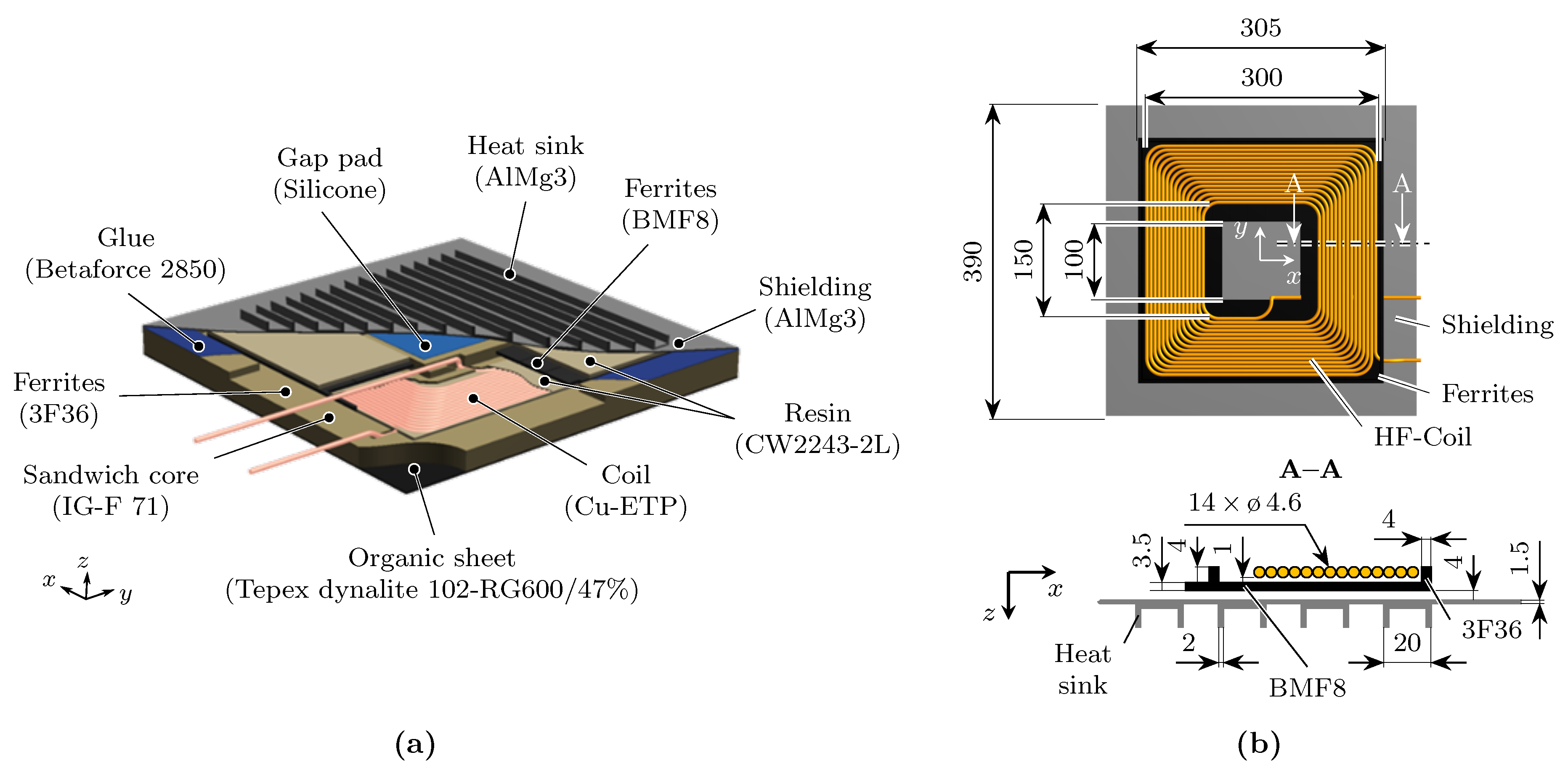
This paper focused on the onboard CPM, which is usually mounted on the underside of EVs due to the operation principle. In particular, the limited installation space in the vehicle underbody requires CPM designs to provide high volumetric and gravimetric power densities combined with low vertical dimensions. For this reason, the authors already presented a sandwich design in [
1].
Thermal management of high-volumetric-power-density CPMs is a major challenge due to the local proximity of the major transformer components—coil, ferrites, and shielding—which cause the largest power losses. Bosshard and Kolar [
2] conducted a multi-objective optimization study on a 50 kW/85 kHz wireless power transfer system (WPTS) by analyzing the power loss distribution of the transformer components. Their findings indicated that the total losses attributed to the coil, ferrites, and shielding exceeded 200 W. Consequently, the prototype was designed with active air cooling, which resulted in a maximum steady-state temperature of 40
in the coil winding. Moghaddami and Sarwat [
3] performed a multi-physics analysis of a 22 kW WPTS based on a 2D simulation model. The results indicated a steady-state temperature over 70
under forced air cooling conditions. The thermal management of different CPM designs, including the proposed sandwich design, was investigated by the authors of this paper under natural convection conditions in [
1]. Depending on the CPM design, the results showed that the maximum temperatures surpassed the maximum operating temperature limit of 130
for some plastic components used.
In order to develop efficient CPMs without having to perform a large number of experimental tests, accurate electromagnetic–thermal simulation models are required. For this reason, the authors of this paper investigated the prediction quality of one-way and two-way coupled simulations using the sandwich design as an example. However, this, study given in [
4], was limited to the module level only considering the CPM without the influence of the external magnetic field caused by the GPM. In detail, the substitutional modeling of the transformer components was verified by experiments at the module level. However, detailed component-level simulations to derive this substitution model were not given therein.
This paper examined the applicability of one-way and two-way coupled simulation models to predict the electromagnetic–thermal behavior of WPTSs for electric vehicles. The paper aimed to provide a quantitative comparison of the respective prediction accuracies based on the analysis of an exemplary CPM design. The presented work approached the investigation in a two-step manner from the component to the module level. First, at the component level, the main transformer components—coil, ferrites, and shielding—were investigated individually to verify the electromagnetic and thermal behavior of each component. This included the component-specific modeling of the power losses, as well as the thermal boundary conditions. The second step was the combination of the component-level models at the module level. At this level, only the proposed CPM design was examined. The interaction with the GPM was neglected in order to verify the modeling without the influence of external fields.
This paper is structured into seven sections based on the study of related works provided in
Section 2.
Section 3 details the proposed CPM design in terms of the construction, electromagnetic specifications, and properties of the used materials.
Section 4 describes the proposed one- and two-way coupled simulation approaches including modeling the power losses of the main transformer components.
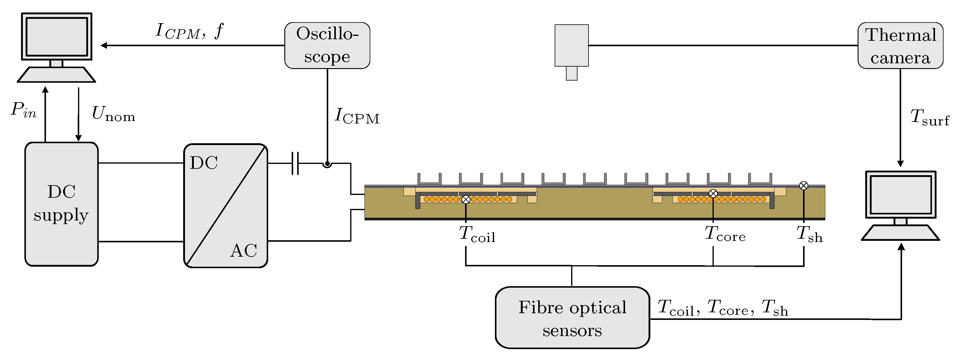
Section 5 presents the experimental setups for the validation of the simulation models.
Section 6 presents the results of the one- and two-way coupled simulations, as well as the experimental measurements at the component and the module level. On this basis, the accuracy of the proposed models is discussed with respect to the electromagnetic–thermal behavior. Finally,
Section 7 provides conclusions and future prospects.
2. Related Works
Coupled simulation approaches are key to predict electromagnetic–thermal behavior. In particular, two-way coupled simulations, linking the electromagnetic and thermal domain bidirectionally, provide very good consistency between simulation and experiment. However, this approach results in high computational costs and efforts due to the complexity of the models. One approach to improve computational efficiency is to use a one-way coupling limiting the exchange of information between the separately calculated electromagnetic and thermal fields. Thus, only the information of the electromagnetic field is considered for the calculation of the thermal field.
Figure 2 shows a schematic comparison of one-way and two-way coupling for calculating electromagnetic–thermal behavior.
In order to predict the thermal management of WPTSs, only a few authors have examined one-way coupled approaches.
Table 1 summarizes the relevant research. Kim et al. [
5] performed a coupled electromagnetic–thermal simulation of a GPM with a double-D coil layout and achieved a very good agreement of the electromagnetic–thermal behavior compared to the experimental validation. However, the modeling of power losses and the thermal distribution of the individual components was not given. Zhang et al. [
6] presented a comprehensive investigation of the thermal performance of a 30 kW WPTS. This study was performed on the system level under the consideration of CPM and GPM including misalignment scenarios and achieved a good consistency of the simulation and experimental validation. However, the temperature of the metal shielding was not given. The authors of this paper already studied the thermal management of the proposed CPM design on the module level. The study showed that power losses in metal parts can cause a significant discrepancy between the experiment and one-way coupled simulation.
Regarding two-way coupling, several authors have performed detailed studies for predicting the electromagnetic–thermal behavior of WPTSs. Amirpour et al. [
8] found good agreement between the numerical and experimental results analyzing an in-road GPM on the module level. Bertoluzzo et al. [
10] presented a magneto-thermal analysis of a WPTS under the consideration of a car frame. However, the analysis and experimental validation were not given. Moghaddami and Sarwat [
3] performed a multiphysics analysis of 22
WPTS coupling time-harmonic electromagnetic, time-dependent, or steady-state thermal and fluid models. However, an experimental validation was not conducted in these studies. Rasekh et al. [
9] conducted a temperature analysis for three substantial pad designs on the system level including misalignments. The results showed a very good agreement between the simulation and experiment. The authors of this paper provided a two-way coupled electromagnetic–thermal simulation model to investigate the electromagnetic–thermal behavior of a functionally integrated CPM with an innovative magnetic core and shielding material [
7]. The study included the systematic modeling and experimental validation of the temperature- and frequency-dependent material properties at the component, module, and system levels. The results showed a very good consistency of the proposed simulations with the experimental validation on all levels.
In summary, both one-way and two-way coupling can be efficient approaches to predict the electromagnetic–thermal behavior of WPTSs. However, only the authors of this paper gave the transient temperature rise of the CPM components being crucial to examine the prediction quality of the simulation approach. To the knowledge of the authors, a quantitative comparison of the one-way and two-way coupled simulation strategies for calculating the electromagnetic–thermal behavior of automotive WPTSs was only given in [
4]. However, this work was limited to the module level, without analyzing the prediction quality on the component level.
4. Simulation Model
The electromagnetic–thermal simulation, both one-way and two-way coupled, was calculated in Comsol Multiphysics. First, one- and two-way coupled simulations were performed on the component level. This means that the models for the litz wire, ferrites, and shielding were implemented, simulated, and validated before all components were combined into a final electromagnetic–thermal model.
The following sections describe the modeling of the magnetic and thermal behavior, with particular emphasis on the coupling between the temperature, the electromagnetic properties, and the power dissipation mechanisms.
4.1. Litz Wire
It was shown in [
7] that the frequency- and temperature-dependent loss density of litz wire
can be accurately calculated from the sum of skin effect losses
and proximity effect losses
The litz wire’s skin and proximity effect loss densities were calculated from the loss densities of a single strand, which were each multiplied by the volumetric litz wire fill factor
; see Equations (
3) and (
4).
and
are temperature- and frequency-dependent, unit-less factors modeling the skin and proximity effect, and
is the linear approximation of the temperature-dependent electrical conductivity of copper.
represents the amplitude value of a single strand’s current density, while
is the amplitude value of the magnetic field strength
to which a single strand is exposed. The volumetric litz wire fill factor
and the current density
are calculated following Equations (
5) and (6):
where
denotes the number of strands per litz wire,
is the cross-sectional area of a single strand,
is the cross-sectional area of the litz wire, and
is the RMS value of the litz wire current.
4.2. Ferrites
The initial magnetic permeability
of the ferrite materials is strongly temperature dependent in the expected operating temperature range, albeit at an already high permeability level. In the previous work [
4], the temperature-dependent permeability was expected to have a small effect; hence, the
average energy method [
22] was applied to account for a high flux density nonlinearity. However, the investigations carried out revealed that the flux densities are in the linear permeability range. Therefore, in this paper, the permeability was modeled as an interpolated look-up function
. This was performed according to the curves provided in the datasheet. The loss density of the ferrites
is calculated from the frequency
f and the amplitude value of the magnetic field strength
according to the temperature-dependent
Steinmetz equation [
23] following Equation (
7):
where
are coefficients, which either are determined by the manufacturer or need to be approximated from the provided manufacturer datasheet. In the case of 3F36, the Steinmetz coefficients were supplied by the manufacturer, whereas the coefficients for BFM8 were determined from the material datasheet supplemented by the experimental data. The coefficients are listed in
Table 3.
4.3. Shielding
The power loss density of the shielding material
was calculated from the current density
J and the material’s electrical conductivity
:
The electrical conductivity
was modeled to be temperature dependent. This was realized by using linear approximation:
where
is the temperature coefficient of the specific material,
is the reference temperature, and
is the electrical conductivity at the reference temperature.
6. Results and Discussion
6.1. Component Level
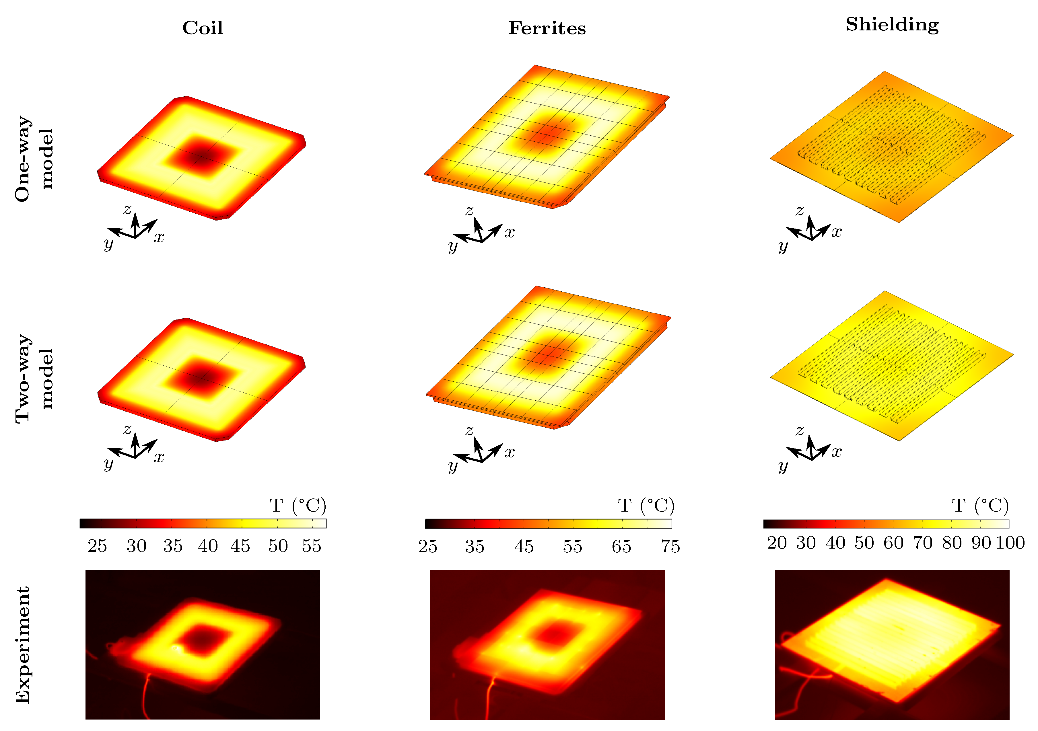
Figure 6 and
Figure 7 show the results of the component-level simulations compared to the measurements. Due to the differences in the thermal mass and loss mechanisms, there was a wide variance in the measurement times to the steady-state (
Figure 7). With respect to the coil and the ferrites, it can be observed that both the one-way and the two-way coupled simulation models resulted in an almost identical temperature distribution at the steady-state, which was in good agreement with the recorded thermographic image from the experiment (
Figure 6). Since there was no feedback from the temperature field to the magnetic field, the exact alignment of the one-way and two-way coupled coil simulations was expected. In contrast, a strong temperature dependence of the initial permeability
was implemented for the ferrite material, resulting in only a small deviation of the observed temperature field. The transient temperature behavior of both models, calculated by averaging the surface temperature, matched the experimental data (
Figure 7). Consequently, the transient curves of the calculated power losses
and
of both simulation approaches agreed qualitatively and quantitatively.
For the shielding component, the two-way coupled simulation model predicted the transient behavior of the mean surface temperature very well compared to the measurements (
Figure 7). As a result, the steady-state temperature distribution matched the experimentally recorded thermographic image (
Figure 6). In contrast, the simulation results showed that the one-way coupled simulation model produced temperatures that were too low for the majority of the experimental time. Thus, both the transient behavior and the steady-state distribution of the top surface deviated by up to 20 K compared to the experimental data. The quantitative comparison of the time-dependent power losses
shown in (
Figure 7) indicated significant differences between the simulation models. In both cases, a steady-state value was reached within the operating time. However, over the course of the experimental time, the calculated shielding losses increased using two-way coupling and decreased using one-way coupling. This was expected due to the positive temperature coefficient of the shielding material, which caused the electrical resistivity of the material to decrease as the temperature increased. This resulted in an increase in the skin depth, changing the eddy current distribution in the two-way coupled simulation. As a consequence, the total losses increased as well. On the contrary, the one-way coupled simulation had a fixed magnetic field solution, resulting in a constant induced electric field. Thus, an increase in material resistivity resulted in a decrease in induced eddy-currents and losses, respectively. However, the assumed heat transfer coefficient
h of 10
on the top surface was considered to be valid due to consistency of the two-way coupled simulation model compared to the measurements.
6.2. Module Level
Figure 8 shows the results of the component-level simulations in comparison with the measurements. In contrast to both simulation results, the transient temperature behavior of the measurement results indicated that the steady-state was not reached after the maximum operating time of 120 min. In most cases, a steady-state comparison was representative for the application of the CPM. However, the authors contend that the use of transient temperature characteristics for model validation is preferable, despite the increased computational cost. This is due to the fact that modeling errors are more easily detected using transient simulations. Furthermore, a transient validated model provides a more accurate representation of the system’s dynamic behavior, enabling the evaluation of different operating scenarios and conditions. Additionally, transient simulations are useful for investigating thermal stress scenarios that may not be apparent in steady-state simulations, while still providing a reasonable prediction of the steady-state temperature under complex heat transfer coefficient conditions. Therefore, only the experimental data resulting from an operating time of 120 min were collected for validation.
Comparing the simulation results, it can be observed that the two-way coupled simulation model provided a better representation of the experimental measurements than the one-way coupled model. Despite not reaching the measured temperatures after 120 min, the two-way coupled model demonstrated a closer agreement with the experimental data. In contrast, the one-way coupled model consistently predicted lower temperatures for the majority of the experimental duration, although the difference between both models was never higher than 5 K. A quantitative comparison indicated that there was a notable effect of additional shielding losses in the two-way simulation, as the highest deviation in temperature of almost 5 K was observable in the shielding after a simulation time of 120 min. The coil and ferrite exhibited similar behavior, but with a reduced deviation. This observation was consistent with the component-level analysis. In the case of the coil, this can be attributed to the lack of thermal–electromagnetic feedback in the one-way coupled model, and although thermal–electromagnetic feedback was implemented for the ferrites, the effect on the temperature or dissipated power was small, as was already observed at the component level. This can also be seen in
Figure 9, in which the time-dependent power losses are compared componentwise. While the coil and ferrites only showed a slight difference in losses over the simulated time, the shield losses diverged right from the beginning. Furthermore, the differences in the coil and ferrite losses can be explained by the generally diverging temperature of the exemplary CPM caused by the shielding losses.
The computational time for the one-way coupled simulation was 1 h and 34 min, whereas the two-way coupled simulation required 8 h and 13 min. Both simulations were performed on an AMD Ryzen 3700X 8-core computer with 46 GB of RAM and using equivalent physics and meshing.
Overall, it was shown that the two-way coupled simulation yielded more accurate results than the one-way coupled simulation, which can mostly be attributed to the diverging power losses of the shielding. However, in combination with other heat sources at the module level, the overall temperature error may be reduced. Furthermore, despite the utilization of a two-way coupled simulation model, the authors acknowledge that the model does not perfectly capture the transient electromagnetic–thermal behavior of the examined CPM yet. The deviations observed were attributed to either inaccuracies in the identification of the material properties or an incorrect estimation of the material quantity within the CPM. Both factors have a significant impact on the total heat capacity and, therefore, on the transient thermal behavior. Additionally, the assumption of a constant heat transfer coefficient is a simplification, as it is a nonlinear function of temperature in reality. Furthermore, the components were validated at lower steady-state temperatures than the module, and higher temperatures may reveal other effects not captured in the transfer coefficient.
7. Conclusions
This paper presented a quantitative comparison of a one-way and a two-way coupling for predicting the electromagnetic–thermal behavior of an exemplary CPM. The investigated CPM was designed as a sandwich and capable of receiving a transmission power of 11 kW at a transmission frequency of 85 kHz. The one-way and the two-way simulation models were developed systematically at the component and module level. At the component level, the results showed that both simulation approaches accurately captured the transient thermal behavior of the coil and ferrites, but the one-way coupled simulation underpredicted the temperature of the shielding. This discrepancy was attributed to the strong impact of the shielding material’s positive temperature coefficient on the magnetic field simulation. The two-way simulation model reproduced this effect better, which was also evident at the module level. As a result, the one-way coupled simulation model produced lower temperatures due to the divergent calculation of shielding losses compared to the two-way coupled simulation. In conclusion, this study found that, in order to correctly predict the thermal behavior of applications with conductive components in alternating magnetic fields, a two-way coupled simulation is advantageous. Further work will include a review of the deviations in transient temperature prediction and a system-level investigation, including the operation with a ground pad module.


