Article

Determining the Deformation Characteristics of Railway Ballast by Mathematical Modeling of Elastic Wave Propagation

1
Department of Transport Infrastructure, Ukrainian State University of Science and Technologies, 49010 Dnipro, Ukraine
2
Central Campus Győr, Széchenyi István University, 9026 Győr, Hungary
*
Author to whom correspondence should be addressed.
Appl. Mech. 2023, 4(2), 803-815; https://doi.org/10.3390/applmech4020041
Submission received: 24 April 2023 / Revised: 17 May 2023 / Accepted: 7 June 2023 / Published: 19 June 2023

Abstract

:
The article solves the problem of theoretically determining the deformable characteristics of railway ballast, considering its condition through mathematical modeling. Different tasks require mathematical models with different levels of detail of certain elements. After a certain limit, excessive detailing only worsens the quality of the model. Therefore, for many problems of the interaction between the track and the rolling stock, it is sufficient to describe the ballast as a homogeneous isotropic layer with a vertical elastic deformation. The elastic deformation of the ballast is formed by the deviation of individual elements; the ballast may have pollutants, the ballast may have places with different levels of compaction, etc. To be able to determine the general characteristics of the layer, a dynamic model of the stress–strain state of the system based on the dynamic problem of the theory of elasticity is applied. The reaction of the ballast to the dynamic load is modeled through the passage of elastic deformation waves. The given results can be applied in the models of the railway track in the other direction as initial data regarding the ballast layer.

1. Introduction

The ballast layer is a complex component of the railway track. The physico-mechanical parameters of the ballast depend on many factors and can significantly change over time during operation. Among the main factors are the accumulation of residual deformations, penetration of pollutants, mixing with soil, and track repair work.
The diversity and complexity of issues related to the use of ballast in railway tracks explain the large number of scientific studies dedicated to this topic. Several modern publications provide detailed reviews of literature sources on this issue, such as in [1,2]. These studies aim to explain the mechanisms of ballast contamination and identify the main factors influencing this process based on an analysis of existing literature sources. According to the authors of [1], 76% of contamination is caused by the destruction of ballast particles, 13% is due to the migration of lower sub-ballast materials, 7% is due to surface infiltration of weathered particles, 3% is due to migration of particles from the earthworks, and 1% is due to wear and tear of sleepers.
Experimental studies have investigated the effects of particle destruction, clay and diesel pollutant infiltration, and the impact of moving trains on the ballast state in papers such as [2,3,4,5,6,7,8,9]. The impact of moving trains becomes particularly relevant when transporting bulk cargoes such as coal and grain [9], as well as with high values of axle loads [10,11].
In [4], the degradation effect of ballast was investigated by gradually changing the granulometric composition in the discrete element model. The approach is based on the assumption that impurities included in the ballast will change the angle of friction between its particles and the contact stiffness of interaction between them.
In such detailed spatial discretization of the ballast layer, not only the physical characteristics of the particles but also their geometric outline become important. Thus, in [5], more than 500 ballast particles were digitally outlined by 3D scanning of railway tracks.
The publications [6,7] summarize the modern results of ballast particle testing for destruction through laboratory research. The conclusion was made in paper [6] that even the best ballast material, based on physical indicators, breaks down no slower than inferior materials.
Ballast degradation interferes with water drainage, further increasing pollutant accumulation intensity [8]. It includes the contamination of ballast with soil particles that hinder water flow (Figure 1). The factors of ballast pollution are analyzed in the example of Hungarian railways in the paper [8].
The deterioration of ballast stiffness characteristics primarily affects the mechanism of sleepers. The formation of voids under sleepers is one of the main reasons for disrupting the geometry of the track as a whole [12,13].
Paper [14] demonstrates that the absence of considering or accounting for the heterogeneity of the ballast layer with inadequate adequacy increases the impact of errors in the mathematical modeling of railway track operation processes. Therefore, this paper proposes mathematical approaches for accounting for the ballast heterogeneity along the sleepers’ length.
To study the evolution of the state of the ballast layer and its degradation, mathematical models with a high level of detail of the ballast structure appear, in some tasks—down to individual gravel particles. It should be understood that, with hyper-detailed models, approaches to creating a mathematical model fundamentally change the degradation of the ballast. For example, if in models with minimal detailing the ballast is a homogeneous isotropic layer that works on compression and has elastic vertical deformations, then in variations with high detailing it is a set (array) of absolutely rigid (non-compressible) bodies of fuzzy shape that work on mutual displacements, taking into account frictional forces, contact stresses, and so on (Figure 1).
In many modern mathematical models of the interaction between the railway track and rolling stock, the ballast is adequately described as a single object (Figure 2), with the main (and, in most cases, the only) mechanical characteristic being the modulus of deformation in the ballasted railway track.
In mathematical models of the interaction between rolling stock and railway track, focused on studying the rolling stock itself, the railway track is typically simplified to a beam resting on a continuous foundation. In this case, the stiffness of the foundation is considered, or it is represented as a rail supported by individual supports (sleepers), and then the stiffness of the railway track is related to the stiffness of the supports. For instance, paper [16] is devoted to simulating the motion of a passenger train on a railway track with irregularities to study the smoothness of motion and passenger comfort. The railway track is represented by individual supports with vertical and horizontal stiffness and damping. The vertical stiffness is set to a constant value of 44 × 106 N/m. Work [17] focuses on modeling the motion of a carriage on a railway track to study the behavior of springs in the bogie. The railway track is represented as a rail with sleepers resting on a sub-slipper layer. The vertical stiffness of the sub-slipper layer is set to 50 MN/m. In study [18], a model of passenger carriage motion is considered. The railway track has a constant vertical stiffness of 1.65 × 10⁸ N/m. Study [19] investigates the oscillations of rolling stock during motion on the railway track. The mathematical model defines the railway track as the vertical stiffness between the wheel and the rail, which is equal to 105 N/m.
Winkler’s model is commonly used to determine the overall stiffness of the railway track as a system composed of elements with different stiffnesses. However, this approach is highly simplified for addressing the given problem and does not account for many aspects of railway track deflection dynamics [20,21,22].
Therefore, the purpose of this study is to find out the influence of ballast degradation and changes in its stiffness characteristics at a detailed level regarding the value of the ballast layer’s modulus of deformation as one of the objects of the railway track and the railway as a whole. To achieve this purpose, the following tasks need to be addressed: selecting an appropriate mathematical model, justifying its adequacy, conducting variant calculations for different states of the ballast, and providing recommendations.

2. Materials and Methods

2.1. Features of the Mathematical Model

In today’s research, mathematical models based on the discrete element method (DEM) [23,24,25] are commonly applied to study the stress–strain state. The authors of these studies opted for a spatial model of dynamic deformations of the railway track based on the theory of elasticity and the propagation of elastic waves [26,27]. The main reasons for this choice are as follows:
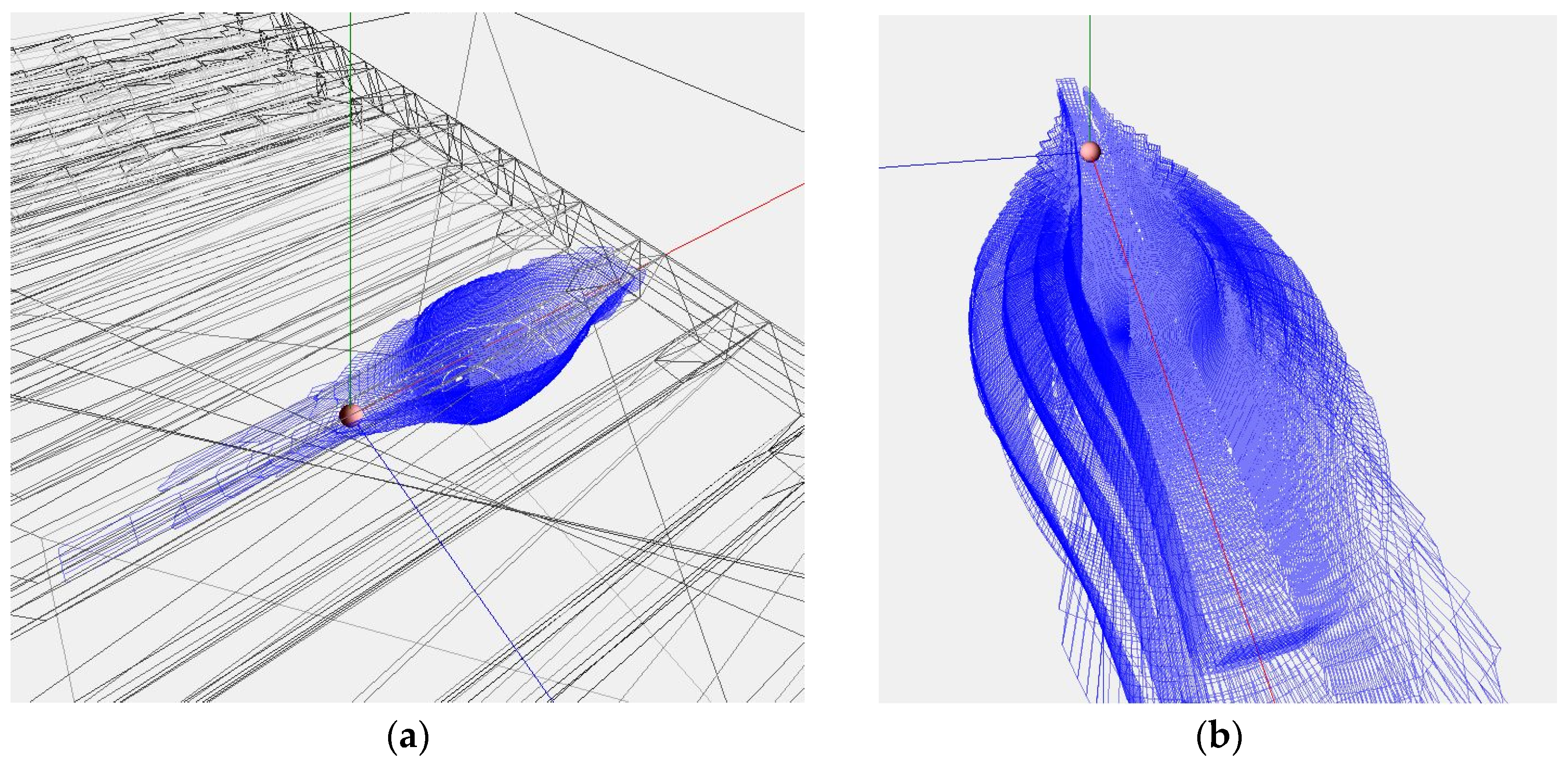
  • The model of elastic wave propagation scales well, allowing for the consideration of a sufficient length and depth of track deflection in the calculations. The spatial configuration involved in the interaction is a result of the modeling rather than being predetermined;
  • It is based on solving mathematical equations for elastic waves rather than considering individual discrete elements, which is less complex in terms of input data, tuning, and computational power;
  • The modeling of elastic wave propagation has a more natural physical interpretation, enabling the understanding of the influence of various factors on the behavior of the ballast and its interaction with moving trains. Such approaches are employed in mathematical models and experimental studies of the ballast layer’s condition [28].
This model’s particularity lies in considering the propagation of an elastic wave as a system’s response to external loads. With each time step of the elastic wave propagation, the system is divided into conditional segments that gradually join the interaction process and are in dynamic equilibrium. Such equilibrium combines the applied load, the elastic reaction of the material that has joined the interaction, and its dynamic deformation. Mathematically, the system’s state is described by a system of Lagrange–D’Alembert differential equations, the solution of which is the stresses and strains in its space. The methodology for constructing the corresponding system of equations is described in [26]. The primary application of mathematical models created according to this principle is the calculation of the stress–strain state of the railway track for high speeds, where the essential condition is the consideration of the volume of material that can participate in the interaction and the time to form an elastic deformation [27]. Such an approach can also be used for other tasks where the railway track needs to be represented as a system whose response to external loads involves a set of elements with different physical–mechanical and geometric characteristics. The geometric dimensions of such elements can be either finite (sleeper, rail fastening) or conditional finite (ballast, subgrade). At a certain moment of the calculation, only a separate part of the objects (for example, a certain number of sleepers) or only a limited fragment of the element (for example, a certain amount of ballast) will participate in the interaction. The formation of the system space involved in the interaction results from determining the current outline of the elastic wave front.
The propagation outline of a wave is calculated through a set of vectors that pass through the medium of the system. The length of each vector at the current time step depends on its direction and the material’s properties that affect the speed of elastic wave propagation in it. The set of vectors is corrected when a vector exits the system or transitions to another material. Thus, the endpoints of the vectors form the current outline of elastic wave propagation. Figure 3 shows an example of the propagation outline in the ballast under the sleeper at the beginning of the ballast layer interaction process. The illustration is provided to visualize the complex outline of the elastic wave formation, which takes into account the positions stated above. Not all railway track elements are displayed in the figure except for the ballast layer to enhance visualization quality. In addition, the step of the outline construction is increased compared with the numerical result calculation of the stressed–deformed state of the system, and the pressure transfer to the ballast is considered only from one sleeper, with the origin (marked by the red sphere) coinciding with the geometric center of the sleeper.
To achieve the goal of this study in accounting for the non-uniformity of the ballast layer, it was assumed that its contamination and hence the change in its properties are uniform along the length of the railway track. Thus, the study focused on the change in the stiffness of the ballast layer with depth and its effect on the overall stiffness of the system.
A unique feature of the differential equation system in this mathematical model [26] is that it avoids the need for a clear boundary between contaminated and clean ballast layers with different stiffness properties. According to the authors, this approach allows for a certain non-uniformity and gradualness of the contamination process, which is more appropriate than the “hard” methods of dividing the ballast into separate layers.

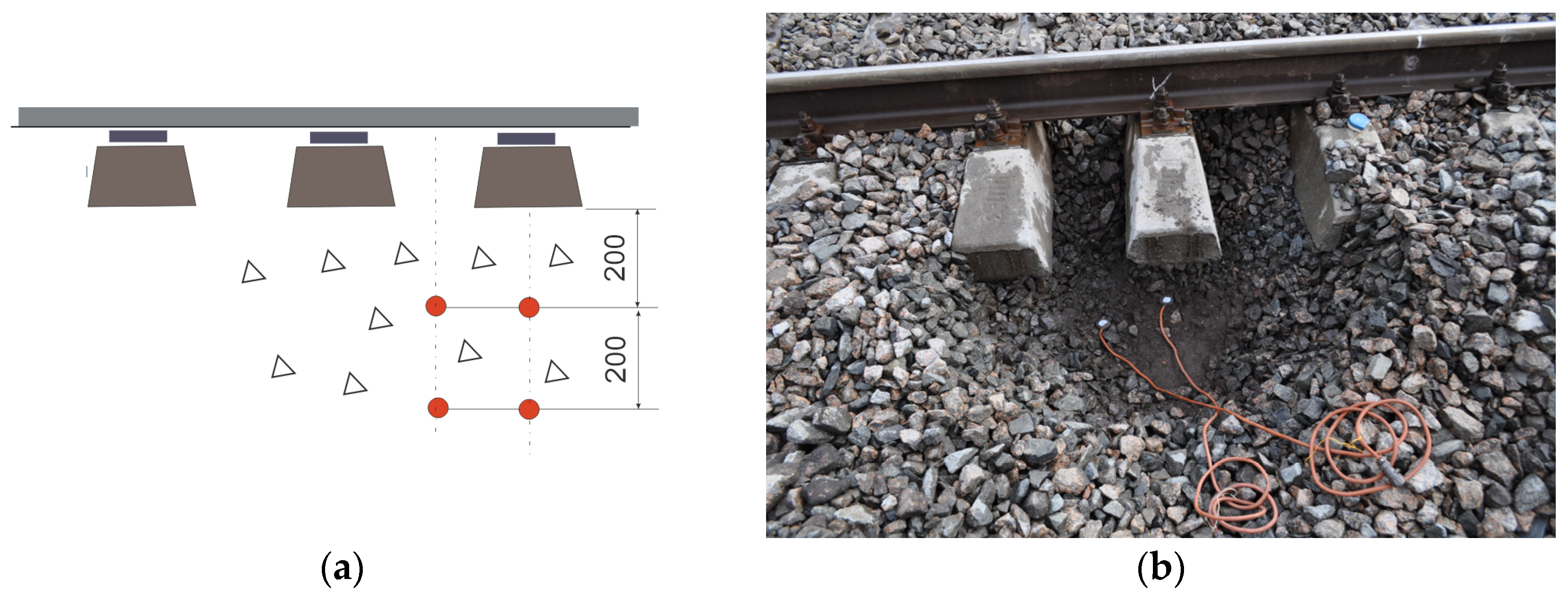
2.2. Validation of the Mathematical Model

The authors have experience in successfully applying this mathematical model to a range of problems related to the interaction between the railway track and rolling stock. During the development and preliminary verification stages, the model underwent corresponding verification steps based on experimental measurements of stresses in railway track elements caused by the rolling stock and on identical analytical calculations. Therefore, this study is limited to a small validation of the model, consisting of comparing experimental and calculated stresses directly in the thickness of the ballast layer.
The main characteristics of the experimental site are as follows: a straight alignment, CWR track (i.e., tracks constructed by continuously welded rails), reinforced concrete sleepers, R65 rails, and a 60 cm thick ballast layer. Stresses were measured using strain gauges installed at depths of 20 and 40 cm below the ballast surface, as shown in Figure 4.
Stress was measured during the movement of a Skoda passenger train’s motor car (static load from the wheel on the rail is 118 kN). The runs were performed at speeds ranging from 60 to 176 km/h. The primary validation results are presented in Table 1.
The model’s accuracy was determined using the standardized error, see Equation (1).
t = x ¯ x m s ,
where x ¯ and s are, respectively, the mean value and standard deviation of the experimental measurement array; and x m is the result of mathematical modeling.
The standardized error (see Equation (1)) is a recognized tool for assessing the discrepancy between observed values and those obtained within the context of a mathematical model. It defines a measure indicating how many standard deviations the observation deviates from the expected value in the model. Based on the number of measurements for each speed level, the confidence interval coefficient ranges from 2.1 to 2.3. It is known that stresses in railway track elements follow a normal distribution with a 2.5   s interval (e.g., [29,30] and others). The obtained standardized error in all variants of the relationship between speed and ballast depth does not exceed the value of 0.811 (see Equation (1)), confirming the adequacy of the mathematical model. The visual comparison of experimental and modeled results is presented in Figure 5. The range from the minimum to maximum observed values during the experiment is indicated for each speed variant. Within this range, the average statistical experimental value is represented by a risk mark, which is also the most probable since the stresses in the ballast follow a Gaussian distribution. These data are overlaid with the corresponding stress calculation results from the mathematical model. The general conclusions regarding the comparison of modeling results with experimental data are positive and based on the following:
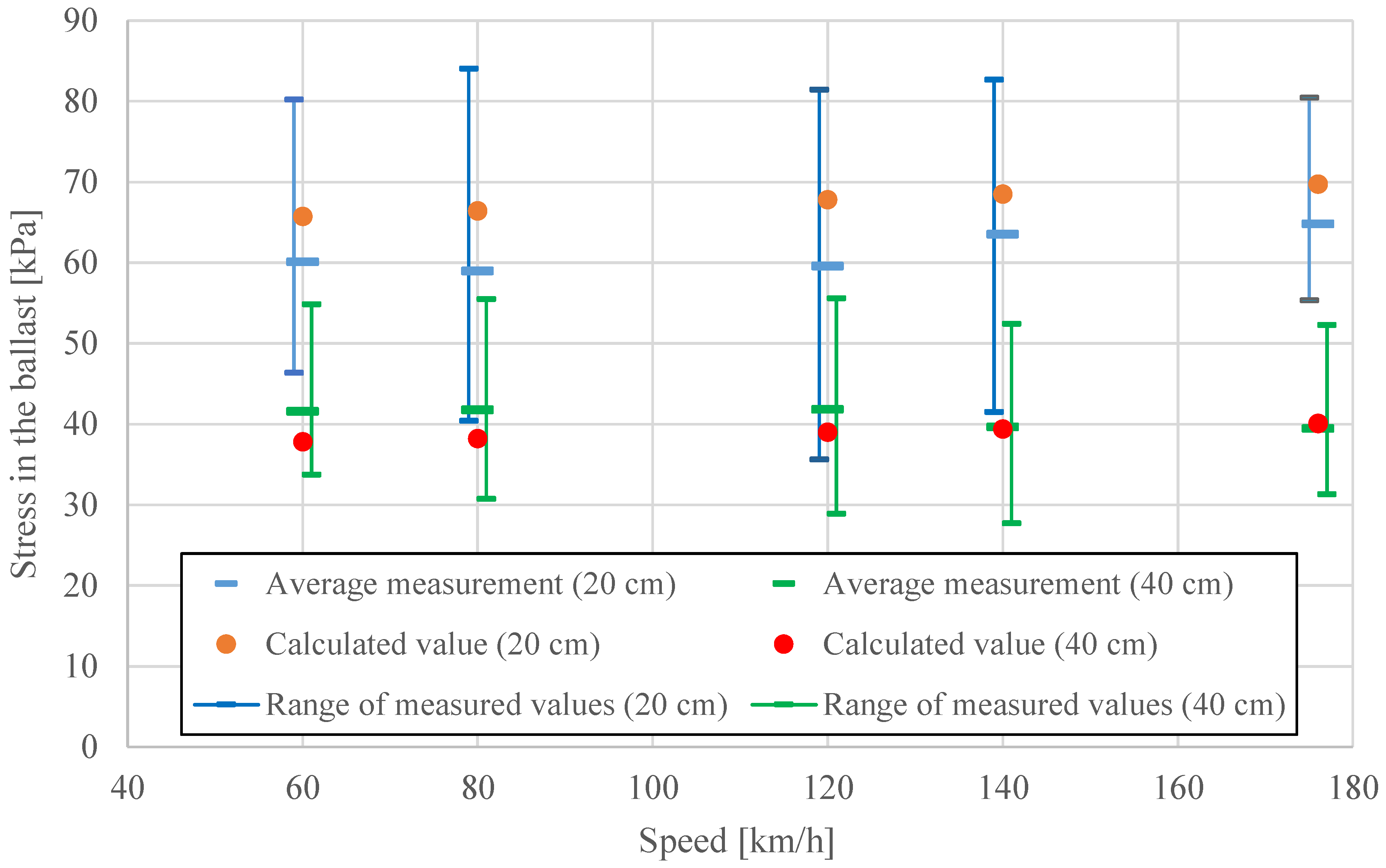
  • The difference between the modeling results and the average experimental values is small and less than expected (see the last column of Table 1);
  • The deviations between the modeling results and the average experimental values are significantly smaller than the range of observations;
  • The modeling results replicate the overall trend of changes in the average experimental values concerning the speed variant and ballast depth.

3. Results

Analysis of the stress–strain state of railway tracks can be carried out using various indicators. The change in ballast stiffness is more clearly reflected in the change of the vertical elastic deformation of the track due to external loads. As the primary numerical indicator, we will consider the total deformation module of the sub-rail base. This term describes the cumulative work on the elastic deformation of the elements of the railway track that provide deflection of the rail: fastenings, sleepers, ballast, and soil. Even a local change in stiffness in the ballast layer affects the stiffness of the entire railway track structure, causing a redistribution of stresses and deformations in the layers located both deeper and higher. The total deformation module of the sub-rail base is the main and, in most cases, the only sufficient characteristic of the railway track in mathematical models of rolling stock, where the railway track is represented only by an elastic surface on which movement takes place. This approach is also widely used in the quasi-static calculation of railway tracks, which describes the rail as a beam lying on an equally elastic base [29,30].
The deformation modulus of the ballast usually ranges from 100 to 200 MPa [15,31], although the specific value depends on various factors. For instance, the size of the stones included in the ballast, their geometric parameters, the level of contamination, and others can affect the deformation modulus. If the ballast is contaminated, the deformation modulus can reduce to 80% of its original value. Furthermore, this value can be 60% in cases of significant contamination.
For the base railway construction, calculations were based on UIC 60 rails, reinforced concrete sleepers, a 60 cm thick ballast layer with a deformation modulus of 100 MPa, and a subgrade filled with soil with a deformation modulus of 35 MPa. The wheel load on the rail was assumed to be 125 kN [8,15]. Deterioration of the ballast condition was modeled by reducing the deformation modulus by 20%.
For further research, multiple calculations were performed for different values of the deformation modulus of the ballast layer and its partial changes at different locations. The results depend on various factors, but certain qualitative regularities were preserved. The main ones are presented below, which reveal the solution to the problem.
Figure 6 displays the deformation gradient of the ballast layer, which illustrates how its deformation changes with depth. The obtained numerical results correspond to the expected values and are consistent with those presented in other studies, such as [32,33]. In this paper, they are obtained to compare the deformation characteristics of the ballast under different conditions. Analyzing the deformation gradient of the ballast layer for different scenarios provides information about the uniformity of deformation distribution within the ballast layer and mechanical properties of the material, and identifies areas where maximum deformations are possible. In both parts of Figure 6, the first scenario shows the change in the deformation gradient for ballast with a deformation modulus of 100 MPa in a pristine state (with no changes in characteristics throughout its thickness). Figure 6a includes information for scenarios that consider the penetration of pollutants at depths of 20, 40, and 60 cm. The presence of pollutants was determined by reducing the deformation modulus of the corresponding layer of the ballast by 20%. Figure 6b varies the position of the polluted zone: 20 cm from the top, 20 cm from the bottom, and 40 cm from the bottom. Typically, more intensive pollution is observed in the upper layers of the ballast because they are subject to more intense wear and contamination due to contact with sleepers, rails, wagons, and weather conditions such as rain and wind. Lower ballast layers may remain cleaner since they are less affected by external factors. However, they may be vulnerable to the penetration of sand and soil particles from lower layers of the railway building.
As seen in Figure 6, the most significant impact is the reduction in stiffness in the upper layer of the ballast down to a depth of 15–20 cm. Further ballast degradation has less significant consequences on the parameter being considered. It is mainly due to significant stresses in this area of the sub-slipper layer. The stresses quickly decay with depth (Figure 7), reducing the effect of material behavior on the formation of overall deformation of the system. Figure 7 illustrates the distribution of stresses beneath the sleeper in the transverse cross-section of the railway track. The horizontal scale represents the coordinate along the length of the sleeper, with the zero mark coinciding with the midpoint of the sleeper. The vertical scale represents the depth beneath the sleeper, initially consisting of the ballast layer and then transitioning to the subgrade soil. As in the previous figure, the zero mark at depth coincides with the bottom of the sleeper. The stresses correspond to the baseline modeling version, representing the moment during motion when the wheel position aligns with the calculated cross-section.
According to the presented methodology, multiple calculations were performed for various input data ratios. The results are summarized in Figure 8 and Table 2. Figure 8 illustrates the relationship between the total modulus of elasticity of the sub-sleeper layer and the stiffness indices of the ballast layer and the subgrade. It allows for a reasoned determination of the overall modulus of sub-rail base elasticity for different ballast and subgrade variations, as well as identifying potential influences on it. To assess the effects of contaminants, the corresponding results are shown with dashed lines concerning the clean ballast state. Several variants of ballast with a deformation modulus ranging from 100 to 200 MPa, both in clean and contaminated states, and several variants of soil with a deformation modulus ranging from 20 to 50 MPa were considered. Using ballast with a higher deformation modulus can ensure greater overall track stiffness.
It should be noted that the stiffness of ballast depends not only on the material’s physical properties but also on the quality of its laying and compaction. Therefore, in some cases, it can be used as an indicator of the quality of railway track maintenance. It is demonstrated that, for weak soils, not only the absolute value of the deformation modulus of the railway track is lost, but also the possibility of increasing it by improving the quality of the ballast layer. For harder soils (with a deformation modulus of 35 MPa and more), the overall modulus of deformation of the substructure at the level of 50 MPa (which is considered sufficient for normal track operation in most cases) is achieved already with the ballast with a deformation modulus of 100–140 MPa. In the case of weak soils (with a deformation modulus of 20 MPa), such track stiffness remains unattainable. Taking into account the presence of contaminated ballast leads to a decrease in the deformation modulus of the sub-rail layer by 6–11%.
The numerical results for the most considered variants are presented in Table 2. In addition to the total deformation module of the sub-rail base, data on the deformation module of the ballast as a whole object of the railway track are included, which can be applied to mathematical models where the sub-rail base is divided into sleepers, ballast, and soil. These data result from deflection modeling that involves the entire railway track structure, enabling the consideration of the overall stress redistribution.

4. Discussion

The authors showed the obtained results in Section 3. The authors investigated the influence of ballast degradation and changes in its stiffness characteristics on the deformation modulus of the ballast layer as a whole, as one of the objects of the railway track. For this purpose, a spatial model of dynamic deformations of the railway track based on elasticity theory was used [26,27]. The basis of such a methodology, which involved modeling the reaction of the railway track to external loads through the propagation of elastic waves, made it possible to study the effect of local changes in ballast stiffness on the stress–strain state of the railway track. Mathematical models of this type allow us, on the one hand, to limit the amount of input data regarding the physical parameters of the environment (geometric dimensions, deformation modulus, density, and Poisson’s ratio) and, on the other hand, to take into account the volume of space involved in the formation of elastic deformation at a given moment of interaction. Additionally, the selected approach made it possible to avoid setting a clear boundary between contaminated and clean layers of ballast, which corresponds to the nature of the process.
According to the results of multivariate calculations, the authors confirmed that even a local change in the stiffness of the ballast layer leads to a redistribution of deformations throughout the entire space of the railway track. The most significant impact on the deformation parameters of the railway track is caused by contamination of the upper layer of ballast with a thickness of up to 20 cm. Further spread of contaminants, or their entry only into the lower ballast layers, leads to lesser consequences.
The application of railway tracks on soft soil can make it impossible to achieve the required overall stiffness of the track, even with the use of high-quality ballast with a high deformation modulus. On the other hand, when there are harder soils present, the required stiffness of the sub-rail base can be achieved without using ballast with a high deformation modulus. However, in this case, the construction becomes more sensitive to contamination of the upper layer of ballast. Therefore, this zone will have the highest stress–strain ratio in such cases and contribute the greatest to the overall deformation level.

5. Conclusions

The authors of this study have analyzed the influence of the ballast layer condition on the vertical deformation modulus of the railway track. A spatial model of dynamic deformations of the railway track based on the theory of elasticity and the propagation of elastic waves was employed as the tool. The primary rationale for choosing such a model was the natural approach, where the deformation process is described as a result of the propagation of an elastic wave induced by an applied excitation. Additionally, this provides the flexibility to consider in the calculations the deformation of, specifically, the region of the system involved in the interaction process.
The authors obtained the results of calculations of the total deformation modulus of the sub-rail base and the deformation modulus of the ballast layer depending on the stiffness and condition of the ballast and soil (Figure 8 and Table 2). These results can be used to set the characteristics of railway tracks in various interaction models between the tracks and rolling stock. Even within the considered range of soil (with a deformation modulus ranging from 25 to 50 MPa) and ballast layer (with a deformation modulus from 80 to 200 MPa), the overall modulus of elasticity of the railway track can vary from approximately 30 to 65 MPa. Other variations in railway track design and deviations from maintenance standards can introduce additional changes. Incorporating the interaction between the moving trains and the track model with justified values of vertical stiffness determines the applicability of the results for railway track design and condition assessment.

Author Contributions

Conceptualization, D.K., M.K. and S.F.; methodology, D.K., M.K. and S.F.; software, D.K.; validation, D.K.; formal analysis, D.K. and S.F.; investigation, D.K., B.H. and S.F.; resources, D.K. and S.F.; data curation, M.K.; writing—original draft preparation, D.K., M.K., B.H. and S.F.; writing—review and editing, D.K., M.K., B.H. and S.F.; visualization, D.K. and S.F.; supervision, M.K. and B.H.; project administration, S.F. All authors have read and agreed to the published version of the manuscript.

Funding

This research received no external funding.

Data Availability Statement

Not applicable.

Acknowledgments

Authors express gratitude to employees of the Railway Track Testing Laboratory of the Ukrainian State University of Science and Technologies as well as the members of the “SZE-RAIL” research team at Széchenyi István University.

Conflicts of Interest

The authors declare no conflict of interest.

References

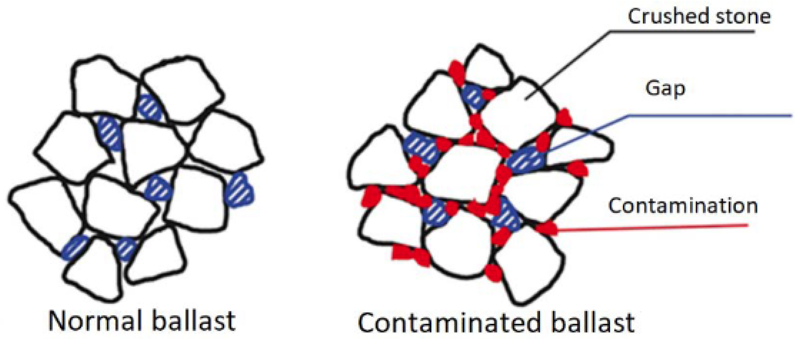
  1. Bassey, D.; Ngene, B.; Akinwumi, I.; Akpan, V.; Bamigboye, G. Ballast Contamination Mechanisms: A Criterial Review of Characterisation and Performance Indicators. Infrastructures 2020, 5, 94. [Google Scholar] [CrossRef]
  2. Bassey, D.; Olukanni, D.O.; Ngene, B.U.; Bamigboye, G. Experimental characterization of track ballast under triple-fouling condition: Evidence from selected Nigerian Railways. Cogent Eng. 2021, 8, 1932240. [Google Scholar] [CrossRef]
  3. Indraratna, B.; Armaghani, D.J.; Correia, A.G.; Hunt, H.; Ngo, T. Prediction of resilient modulus of ballast under cyclic loading using machine learning techniques. Transp. Geotech. 2022, 38, 100895. [Google Scholar] [CrossRef]
  4. Wang, L.; Meguid, M.; Mitri, H. Impact of Ballast Fouling on the Mechanical Properties of Railway Ballast: Insights from Discrete Element Analysis. Processes 2021, 9, 1331. [Google Scholar] [CrossRef]
  5. Xiao, J.; Zhang, X.; Zhang, D.; Xue, L.; Sun, S.; Stránský, J.; Wang, Y. Morphological reconstruction method of irregular shaped ballast particles and application in numerical simulation of ballasted track. Transp. Geotech. 2020, 24, 100374. [Google Scholar] [CrossRef]
  6. Juhász, E.; Fischer, S. Investigation of railroad ballast particle breakage. Pollack Period. 2019, 14, 3–14. [Google Scholar] [CrossRef]
  7. Mohammed, A.; Amartey, Y.D.; Murana, A.A.; Lawan, A. Comparative Evaluation of Railway Ballast Degradation. FUOYE J. Eng. Technol. 2022, 7, 90–95. [Google Scholar] [CrossRef]
  8. Eller, B.; Fischer, S. Tutorial on the emergence of local substructure failures in the railway track structure and their renewal with existing and new methodologies. Acta Tech. Jaurinensis 2021, 14, 80–103. [Google Scholar] [CrossRef]
  9. Pittman, R.; Jandová, M.; Król, M.; Nekrasenko, L.; Paleta, T. The effectiveness of EC policies to move freight from road to rail: Evidence from CEE grain markets Research in Transportation. Bus. Manag. 2020, 37, 100482. [Google Scholar] [CrossRef]
  10. Pshinko, O.; Patlasov, O.; Andrieiev, V.; Arbuzov, M.; Hubar, O.; Hromova, O.; Markul, R. Research of railway crashed stone use of 40–70 mm fraction. In Proceedings of the 22nd International Scientific on Conference Transport Means 2018, Trakai, Lithuania, 3 October 2018; pp. 170–178. [Google Scholar]
  11. Shvets, A.O. Dynamic interaction of a freight car body and a three-piece bogie during axle load increase. Veh. Syst. Dyn. 2022, 60, 3291–3313. [Google Scholar] [CrossRef]
  12. Sysyn, M.; Przybylowicz, M.; Nabochenko, O.; Liu, J. Mechanism of Sleeper–Ballast Dynamic Impact and Residual Settlements Accumulation in Zones with Unsupported Sleepers. Sustainability 2021, 13, 7740. [Google Scholar] [CrossRef]
  13. Havryliuk, V. Fault Detecting of Turnouts Using DWT and ANN. In Proceedings of the 2021 IEEE International Conference on Modern Electrical and Energy Systems, Kremenchuk, Ukraine, 21–24 September 2021. [Google Scholar] [CrossRef]
  14. Hu, Q.; Lam, H.F.; Alabi, S.A. Use of Measured Vibration of In-Situ Sleeper for Detecting Underlying Railway Ballast Damage. Int. J. Struct. Stab. Dyn. 2015, 15, 1540026. [Google Scholar] [CrossRef]
  15. Fischer, S.; Eller, B.; Zoltán, K.; Németh, A. Railway Construction; Universitas Győr Nonprofit Kft.: Győr, Hungary, 2015. [Google Scholar]
  16. Sattari, S.; Saadat, M.; Mirtalaie, S.H.; Salehi, M.; Soleimani, A. Evaluation of Sperling’s index in passenger and freight trains under different speeds and track irregularities. Adv. Des. Manuf. Technol. 2022, 15, 87–96. [Google Scholar] [CrossRef]
  17. Sharma, S.K.; Sharma, R.C.; Lee, J. Effect of Rail Vehicle-Track Coupled Dynamics on Fatigue Failure of Coil Spring in a Suspension System. Appl. Sci. 2021, 11, 2650. [Google Scholar] [CrossRef]
  18. Dižo, J.; Blatnický, M. Influence of stiffness characteristics of a railway track on output parameters in a multibody model. In Proceedings of the 7th International Conference of Materials and Manufacturing Engineering (ICMMEN), Thessaloniki, Greece, 2–3 July 2020; EDP Sciences: Les Ulis, France, 2020; Volume 318, p. 01003. [Google Scholar] [CrossRef]
  19. Sattari, S.; Saadat, M.; Mirtalaie, S.H.; Salehi, M.; Soleimani, A. Modeling of a rail suspension system to investigate vertical vibration and effective parameters on it. Int. J. Railw. Res. 2022, 9, 1–20. [Google Scholar]
  20. Wehbi, M.; Musgrave, P. Optimisation of Track Stiffness on the UK Railways. Perm. Way Inst. 2017, 135, 24–31. [Google Scholar]
  21. Balcı, E.; Bezgin, N.Ö. Analytical Estimation of Dynamic Impact Forces on Railway Tracks Considering Railway Track and Rolling Stock Stiffness. In Proceedings of the 8th International Geotechnical Symposium, Istanbul, Turkey, 13–15 November 2019. [Google Scholar]
  22. Lamprea Pineda, A.C.; Connolly, D.P.; Hussein, M.F.M. Beams on elastic foundations—A review of railway applications and solutions. Transp. Geotech. 2021, 33, 100696. [Google Scholar] [CrossRef]
  23. Balamonica, K.; Bergamini, A.; Damme, B.V. Estimation of the dynamic stiffness of railway ballast over a wide frequency range using the discrete element method. J. Sound Vib. 2023, 547, 117533. [Google Scholar] [CrossRef]
  24. Suhr, B.; Six, K. Efficient DEM simulations of railway ballast using simple particle shapes. Granular Matter 2022, 24, 114. [Google Scholar] [CrossRef] [PubMed]
  25. Tolomeo, M.; McDowell, G.R. DEM study of an “avatar” railway ballast with real particle shape, fabric and contact mechanics. Granular Matter 2023, 25, 32. [Google Scholar] [CrossRef]
  26. Kurhan, D.; Kurhan, M. Modeling the Dynamic Response of Railway Track. In IOP Conference Series: Materials Science and Engineering; IOP Science: Bristol, UK, 2019; Volume 708, p. 012013. [Google Scholar] [CrossRef]
  27. Kurhan, D.; Fischer, S. Modeling of the Dynamic Rail Deflection using Elastic Wave Propagation. J. Appl. Comput. Mech. 2022, 8, 379–387. [Google Scholar] [CrossRef]
  28. Sysyn, M.; Gerber, U.; Liu, J.; Fischer, S. Studying the Relation of the Residual Stresses in the Ballast Layer to the Elastic Wave Propagation. Transp. Infrastruct. Geotechnol. 2022. [Google Scholar] [CrossRef]
  29. Sysyn, M.; Gerber, U.; Kovalchuk, V.; Nabochenko, O. The complex phenomenological model for prediction of inhomogeneous deformations of railway ballast layer after tamping works. Arch. Transp. 2018, 47, 91–107. [Google Scholar] [CrossRef] [Green Version]
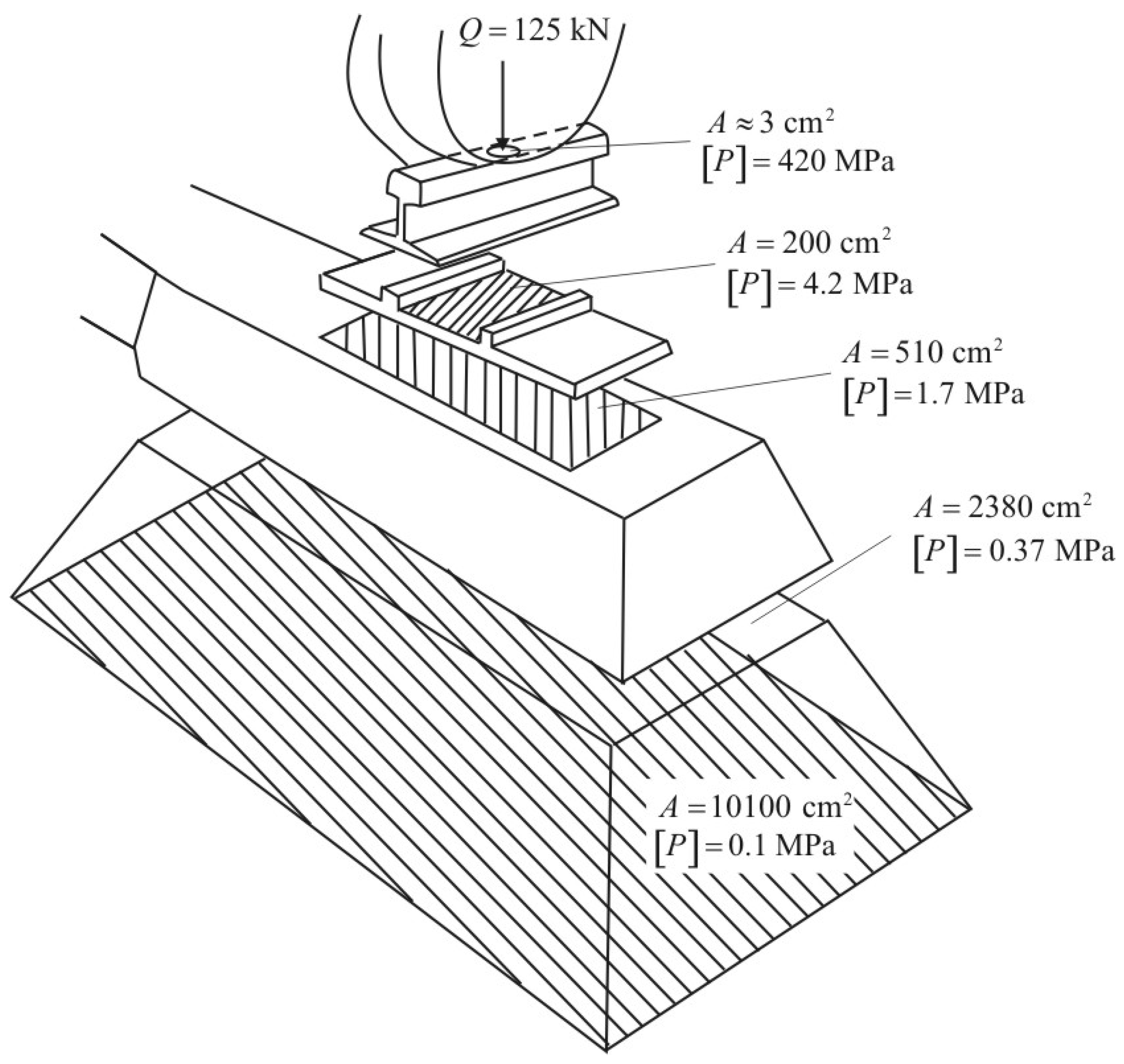
  30. Kurhan, D. Determination of Load for Quasi-static Calculations of Railway Track Stress-strain State. Acta Tech. Jaurinensis 2016, 9, 83–96. [Google Scholar] [CrossRef] [Green Version]
  31. Cescon, J.T.A.M.; de Albuquerque e Silva, B.-H.; Marque, M.E.S.; Santos, R.P. Evaluation of the viability of recycling railroad ballast for reusing in railroads. Res. Soc. Dev. 2021, 10, e277101321231. [Google Scholar] [CrossRef]
  32. Jideani, T.; Gräbe, H. Identifying Suitable Ballast Settlement Models and Types of Ballast Breakage from Field Representative Ballast Box Tests. In Proceedings of the Fifth International Conference on Railway Technology, Edinburgh, UK, 22–25 August 2022. [Google Scholar]
  33. Wang, H.; Xing, C.; Deng, X. Effect of Random Lateral Ballast Resistance on Force-Deformation Characteristics of CWR with a Small-Radius Curve. Materials 2023, 16, 2876. [Google Scholar] [CrossRef]
Figure 1. The contamination of the ballast based on [8].
Applmech 04 00041 g001
Figure 2. The load distribution in the railway superstructure on the basis of [8,15].
Applmech 04 00041 g002
Figure 3. Example of forming the outline of the elastic wave front in the ballast layer: (a) at one time step; and (b) changing the outline with steps.
Applmech 04 00041 g003
Figure 4. Placing mesoscopes (strain gauges) in the ballast layer: (a) installation scheme (the units are in mm); and (b) experimental site.
Applmech 04 00041 g004
Figure 5. Comparison of experimental and calculated stresses in ballast.
Applmech 04 00041 g005
Figure 6. Deformation gradient of the ballast layer: (a) penetration of pollutants at different depths; and (b) varying position of the contaminated zone. The depth values are determined from the bottom surface of the sleeper; its height is ±0.0 cm.
Applmech 04 00041 g006
Figure 7. Propagation of stresses in the sub-sleeper layer in cross-section.
Applmech 04 00041 g007
Figure 8. Dependence of the general deformation modulus of the sub-rail base on the characteristics of the ballast and soil.
Applmech 04 00041 g008
Table 1. Comparison of experimental and calculated stresses in ballast.
Depth in Ballast [cm]Speed, [km/h]Measured Stresses [kPa]Number of PassesCalculated Stresses,
x m [kPa]
Model Adequacy Criterion, t
Mean, x ¯ Standard Deviation, s MinimumMaximum
206060.19.7346.380.2865.70.578
8059.09.7640.484.12066.40.765
12059.610.1835.681.51267.80.811
14063.59.8741.582.71568.50.505
17664.86.9155.380.51069.80.718
406041.65.6133.754.9837.80.675
8041.85.7630.855.52038.20.622
12041.86.3228.955.61239.00.444
14039.66.3327.752.41539.40.042
17639.45.2731.452.31040.10.127
Table 2. Deformation modulus of the railway on the characteristics of the ballast and soil.
Initial CharacteristicsSimulation Results
Deformation Modulus of the Ballast Layer [MPa]Deformation Modulus of the Soil [MPa]Deformation Modulus of the “Ballast” Object [MPa]Deformation Modulus of the “Sub-Rail” Object [MPa]
0–20 cm20–40 cm40–60 cm
1002010026.0
1003510041.2
801008738.7
801008037.1
808037.1
606031.9
909039.2
12012044.4
15015048.5
12015011844.1
20020053.7
16020016149.6
80258031.4
10010034.4
8010010531.1
15015039.8
12015014836.6
20020043.4
16020019540.6
80508043.4
10010048.9
801008143.4
12012053.3
15015059.1
12015011752.9
20020066.5
16020015960.6
Disclaimer/Publisher’s Note: The statements, opinions and data contained in all publications are solely those of the individual author(s) and contributor(s) and not of MDPI and/or the editor(s). MDPI and/or the editor(s) disclaim responsibility for any injury to people or property resulting from any ideas, methods, instructions or products referred to in the content.

