Fatigue Life Analysis of Automotive Cast Iron Knuckle under Constant and Variable Amplitude Loading Conditions

 ,
,
Abstract
:1. Introduction
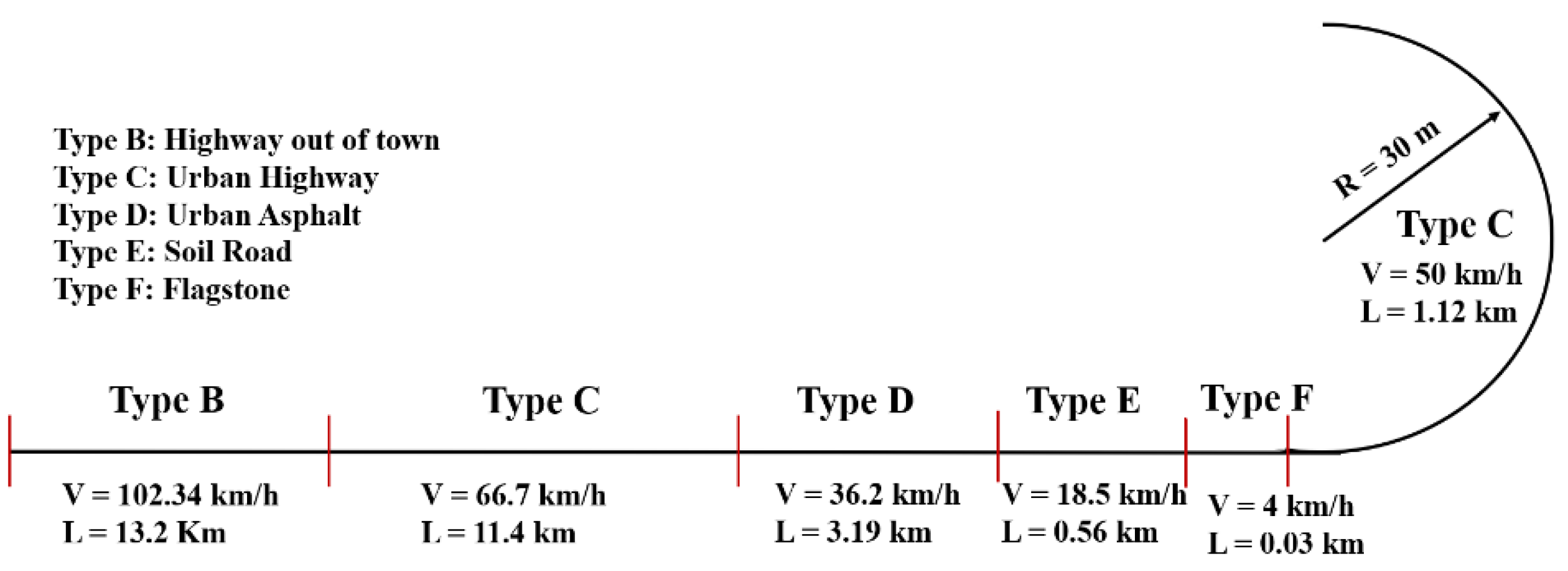
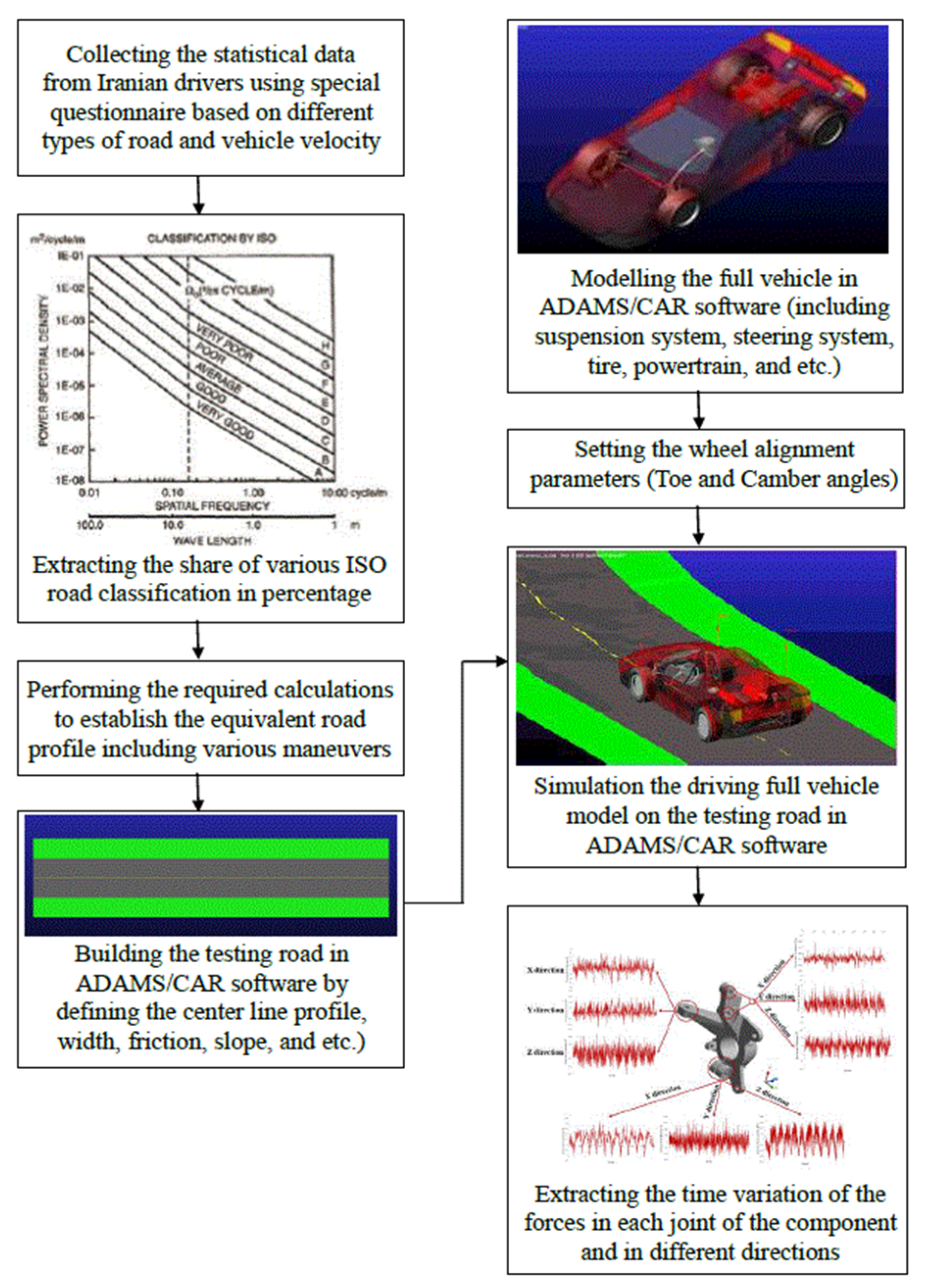
- Considering the equivalent road involves different maneuvers and various speeds;
- Driving simulation of a full vehicle model (taking into account the masses, inertia, and actual characteristics of the car) on the real road in the MBD software (Adams/Car, MSC Software Company, Irvine, CA, USA);
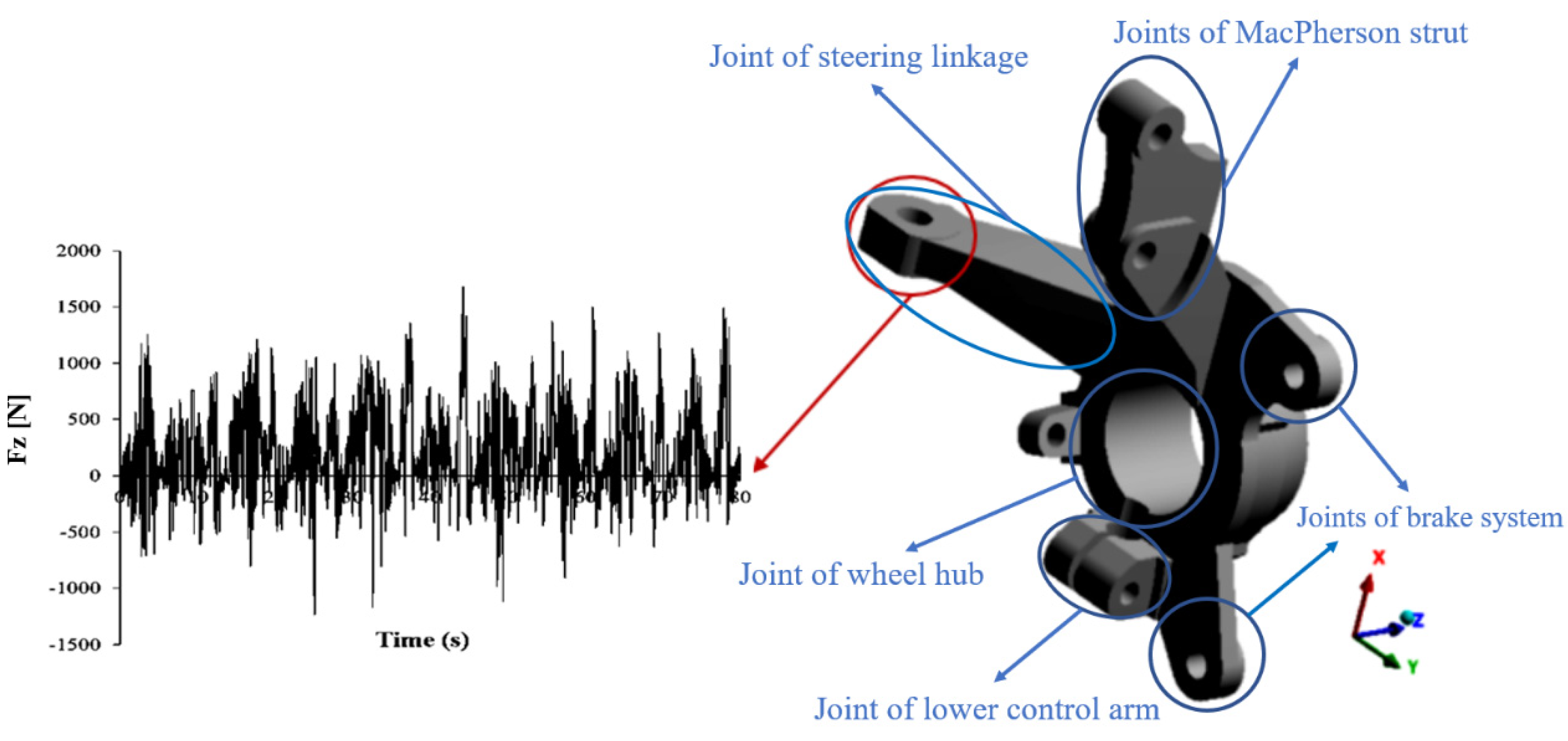
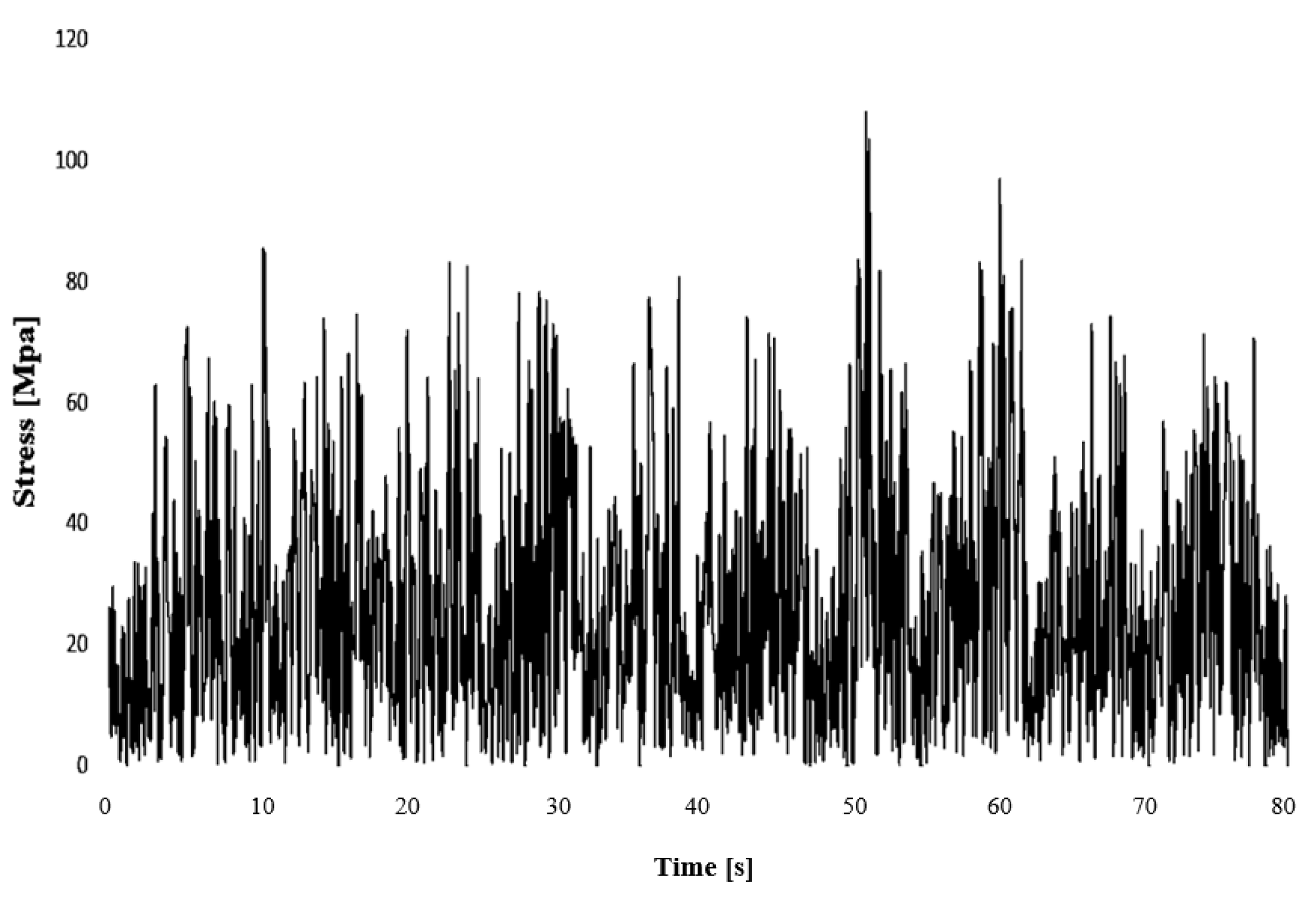
- Extracting the time histories of loads applied to the steering knuckle connections in different directions as a result of crossing a real road;
- Use of different methodologies to convert VAL to CAL based on the assumption of the same fatigue damage;
- Assessing the fatigue life of cast iron steering knuckle in both constant and variable amplitude loading based on the real road conditions and a combination of actual maneuvers, and finally, compared with full-scale laboratory results.
2. Material
3. MBD Analysis of Full Vehicle Model
4. Finite Element Model
5. Fatigue Life Prediction
5.1. Using Some Well-Known Criteria for Equalization of Load Spectrum to a CAL
5.1.1. Goodman Criterion
5.1.2. Soderberg Criterion
5.1.3. Gerber Criterion
5.2. Fatigue Analysis Considering Actual Loading Conditions
6. Results and Discussion
7. Conclusions
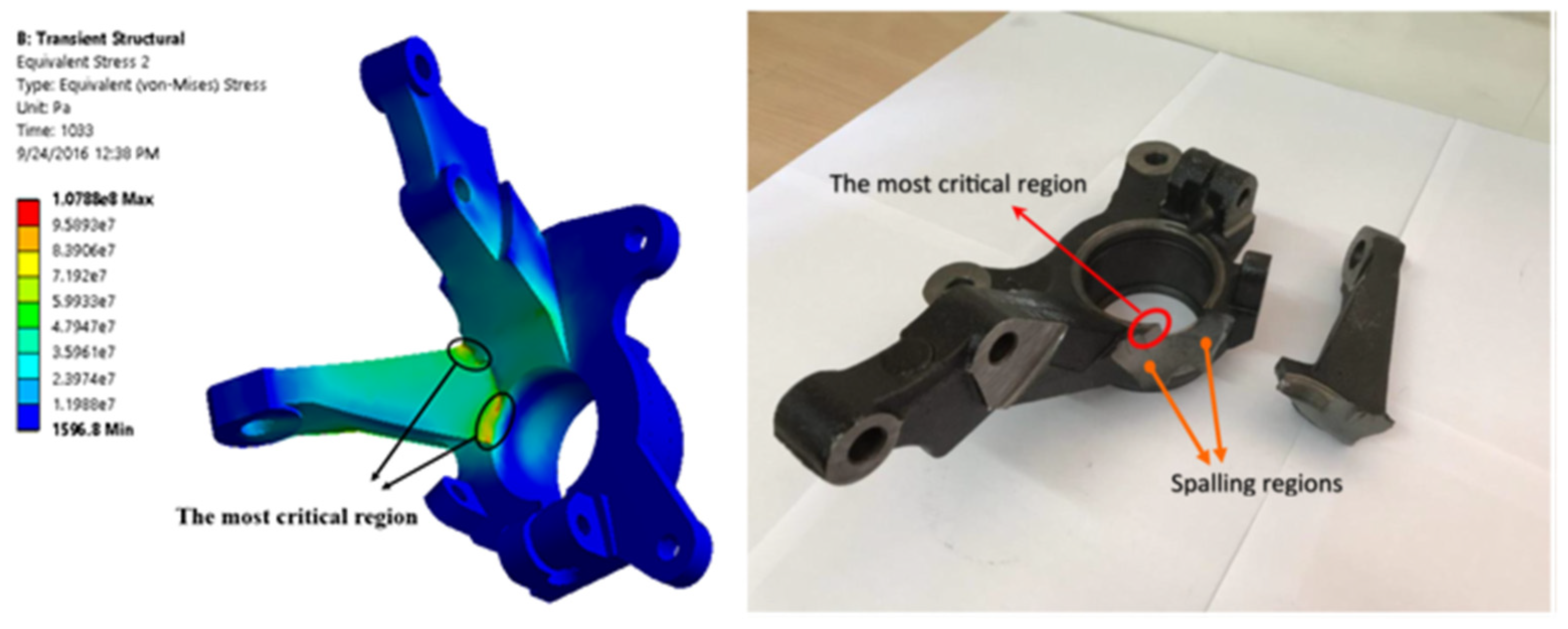
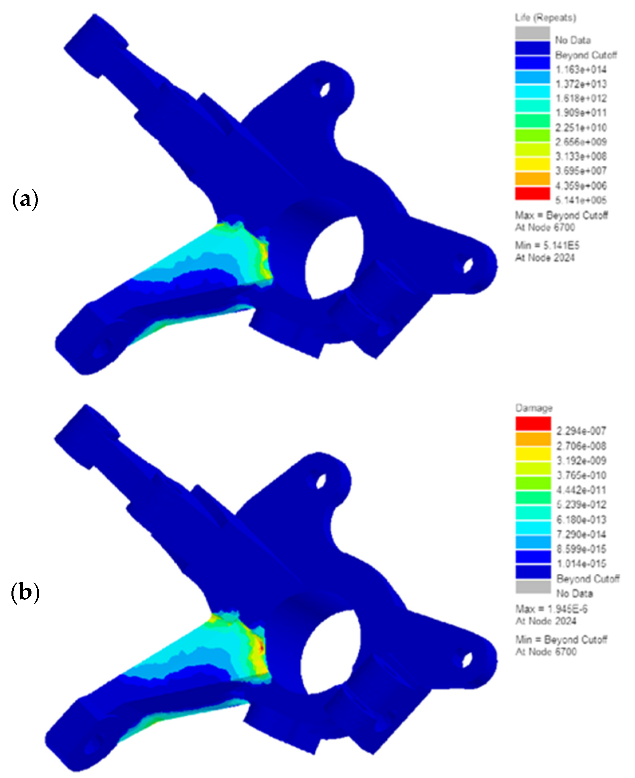
- The results of the stress analysis showed that the critical area detected by the present finite element model is consistent with the fracture zone under the axial fatigue test with variable amplitude loading. On the other hand, the finite element model presented in this study can identify the fracture region in industrial components with complex geometries and tough loading conditions.
- According to the findings of the present research, the prediction of variable amplitude fatigue lifetime by FE analysis in the time domain has about a 21% difference compared to reality. Additionally, the obtained results are acceptable due to the data scattering in this phenomenon and the complex geometry of the component. However, the von Misses equivalent stress is not accurate for non-proportional loading conditions.
- The methodology of simplifying the loading history and converting the VAL to CAL by using different criteria to check the effects of mean stress in the calculations showed that 40–55% error is created compared to reality. However, due to the time consuming nature of other methodologies, this load conversion methodology can be used for the primary studies.
- The results showed that for this case study, the best criteria for converting VAL to CAL with the aim of estimating fatigue life are Gerber, Soderberg, and Goodman criteria, respectively with approximately 40, 51, and 56% error relative to reality.
- The results of this study indicated that the relative error between the results obtained from two different methodologies is 20%, and compared to the reduction in computational costs, this error is negligible (in the initial research phase).
Author Contributions
Funding
Institutional Review Board Statement
Informed Consent Statement
Data Availability Statement
Acknowledgments
Conflicts of Interest
References
- Rama Krishna, L.; Madhavi, Y.; Sahithi, T.; Srinivasa Rao, D.; Ijeri, V.S.; Prakash, O.; Gaydos, S.P. Enhancing the high cycle fatigue life of high strength aluminum alloys for aerospace applications. Fatigue Fract. Eng. Mater. Struct. 2019, 42, 698–709. [Google Scholar] [CrossRef]
- Vijayanandh, R.; Kumar, K.N.; Kumar, G.R.; Sanjeev, B.; Balachander, H.; Prasad, S.G. Comparative approaches for fatigue life estimation of aluminium alloy for aerospace applications. Int. J. Veh. Struct. Syst. 2018, 10, 282–286. [Google Scholar] [CrossRef]
- Abdollahnia, H.; Alizadeh Elizei, M.H.; Reza Kashyzadeh, K. Multiaxial Fatigue Life Assessment of Integral Concrete Bridge with a Real-Scale and Complicated Geometry Due to the Simultaneous Effects of Temperature Variations and Sea Waves Clash. J. Mar. Sci. Eng. 2021, 9, 1433. [Google Scholar] [CrossRef]
- Petrini, F.; Bontempi, F. Estimation of fatigue life for long span suspension bridge hangers under wind action and train transit. Struct. Infrastruct. Eng. 2011, 7, 491–507. [Google Scholar] [CrossRef]
- Abdollahnia, H.; Alizadeh Elizei, M.H.; Reza Kashyzadeh, K. Fatigue life assessment of integral concrete bridges with H cross-section steel piles mounted in water. J. Fail. Anal. Prev. 2020, 20, 1661–1672. [Google Scholar] [CrossRef]
- Ktari, A.; Haddar, N.; Rezai-Aria, F.; Ayedi, H.F. On the assessment of train crankshafts fatigue life based on LCF tests and 2D-FE evaluation of J-integral. Eng. Fail. Anal. 2016, 66, 354–364. [Google Scholar] [CrossRef]
- Amiri, N.; Shaterabadi, M.; Reza Kashyzadeh, K.; Chizari, M. A Comprehensive Review on Design, Monitoring, and Failure in Fixed Offshore Platforms. J. Mar. Sci. Eng. 2021, 9, 1349. [Google Scholar] [CrossRef]
- Kashyzadeh, K.R.; Arghavan, A. Study of the effect of different industrial coating with microscale thickness on the CK45 steel by experimental and finite element methods. Strength Mater. 2013, 45, 748–757. [Google Scholar] [CrossRef]
- Lee, Y.L.; Pan, J.; Hathaway, R.; Barkey, M. Fatigue Testing and Analysis: Theory and Practice; Butterworth-Heinemann: Oxford, UK, 2005; Volume 13, ISBN 0-7506-7719-8. [Google Scholar]
- Arghavan, A.; Reza Kashyzadeh, K.; Asfarjani, A.A. Investigating effect of industrial coatings on fatigue damage. In Applied Mechanics and Materials; Trans Tech Publications Ltd.: Bäch, Switzerland, 2011; Volume 87, pp. 230–237. [Google Scholar] [CrossRef]
- Vijayarangan, S.; Rajamanickam, N.; Sivananth, V. Evaluation of metal matrix composite to replace spheroidal graphite iron for a critical component, steering knuckle. Mater. Des. 2013, 43, 532–541. [Google Scholar] [CrossRef]
- Sivananth, V.; Vijayarangan, S. Fatigue Life analysis and optimization of a passenger car steering knuckle under operating conditions. Int. J. Automot. Mech. Eng. 2015, 11, 2417–2429. [Google Scholar] [CrossRef]
- Reza Kashyzadeh, K.; Farrahi, G.H.; Shariyat, M.; Ahmadian, M.T. Experimental and finite element studies on free vibration of automotive steering knuckle. Int. J. Eng. 2017, 30, 1776–1783. [Google Scholar] [CrossRef]
- Dumbre, P.; Mishra, A.K.; Aher, V.S.; Kulkarni, S.S. Structural analysis of steering knuckle for weight reduction. Int. J. Emerg. Technol. Adv. Eng. 2014, 4, 552–557. [Google Scholar]
- Madhusudhanan, S.; Rajendran, I.; Prabu, K. Static analysis of automotive steering knuckle. In Applied Mechanics and Materials; Trans Tech Publications Ltd.: Bäch, Switzerland, 2014; Volume 592, pp. 1155–1159. [Google Scholar] [CrossRef]
- Dusane, S.V.; Dipke, M.K.; Kumbhalkar, M.A. Analysis of steering knuckle of all terrain vehicles (ATV) using finite element analysis. In IOP Conference Series: Materials Science and Engineering; IOP Publishing: Bristol, UK, 2016; Volume 149, p. 12133. [Google Scholar]
- Sharma, M.P.; Denish, S.M.; Joshi, H.; Patel, D.A. Static analysis of steering knuckle and its shape optimization. J. Mech. Civ. Eng. 2014, 4, 34–38. [Google Scholar]
- Kadam, S.R.; Kale, P.D. Finite Element Analysis and Optimization of Automotive Steering Knuckle. J. Interdiscip. Cycle Res. 2020, 12, 115–119. [Google Scholar]
- Tang, G.; Shi, B.; Zhang, W. Structural response surface optimization design of steering knuckle arms under multiple working conditions based on fuzzy evaluation. J. Eng. Sci. 2013, 35, 1368–1374. [Google Scholar] [CrossRef]
- Lee, Y.C.; Jeon, N.J.; Kim, C.; Ahn, S.Y.; Cho, M.J. Shape optimization of a small bus steering knuckle considering a fatigue load. In Advanced Materials Research; Trans Tech Publications Ltd.: Bäch, Switzerland, 2013; Volume 740, pp. 319–322. [Google Scholar] [CrossRef]
- Teja, G.P.C.; Chandu, K.V.P.P.; Krishna, C.R.; Sreeram, K.Y. Weight optimization of steering knuckle joint using FEA. Int. Res. J. Eng. Technol. IRJET 2016, 3. Available online: https://www.irjet.net/archives/V3/i12/IRJET-V3I12107.pdf (accessed on 26 March 2022).
- Tagade, P.P.; Sahu, A.R.; Kutarmare, H.C. Optimization and finite element analysis of steering knuckle. Int. J. Comput. Appl. 2015, 975, 8887. [Google Scholar]
- Borns, R.; Whitacre, D. Optimizing Designs of Aluminum Suspension Components Using an Integrated Approach (No. 2005-01-1387); SAE Technical Paper; SAE International: Warrendale, PA, USA, 2005. [Google Scholar] [CrossRef]
- Shelar, M.L.; Khairnar, H.P. Design Analysis and Optimization of Steering Knuckle Using Numerical Methods and Design of Experiments. 2014. Available online: www.ijedr.org/papers/IJEDR1403012.pdf (accessed on 26 March 2022).
- Vivekananda, R.; Mythra Varun, A.V. Finite element analysis and optimization of the design of steering knuckle. Int. J. Eng. Res. 2016, 4, 121–135. [Google Scholar]
- Babu, B.; Prabhu, M.; Dharmaraj, P.; Sampath, R. Stress analysis on steering knuckle of the automobile steering system. Int. J. Res. Eng. Technol. 2014, 3, 363–366. [Google Scholar]
- Pingqing, F.; Bo, Z.; Long, Q. The analysis on destruction forms of steering knuckle. In Proceedings of the 2011 Third International Conference on Measuring Technology and Mechatronics Automation, Shanghai, China, 6–7 January 2011; IEEE 2011. Volume 3, pp. 677–679. [Google Scholar] [CrossRef]
- Madhusudhanan, S.; Kumar, K.A.; Kumar, V.P.; Mahendran, T. Fatigue analysis of automative steering knucle. Mech. Mech. Eng. 2016, 20, 5–13. [Google Scholar]
- Kamal, M.; Rahman, M.M.; Rahman, A.G.A. Fatigue life evaluation of suspension knuckle using multi body simulation technique. J. Mech. Eng. Sci. 2012, 3, 291–300. [Google Scholar] [CrossRef]
- Azrulhisham, E.; Asri, Y.M.; Dzuraidah, A.W.; Nik Abdullah, N.M.; Che Hassan, C.H.; Shahrom, A. EquilibriumApplication of Road Simulator Service Loads in Automotive Component Durability Assessment. Open Ind. Manuf. Eng. J. 2011, 4, 1–7. [Google Scholar]
- Niu, X.Y.; Wang, G.X.; Li, W. Finite element analysis of the car steering knuckle based on ANSYS. In Applied Mechanics and Materials; Trans Tech Publications Ltd.: Bäch, Switzerland, 2015; Volume 740, pp. 108–111. [Google Scholar] [CrossRef]
- Sivananth, V.; Vijayarangan, S.; Rajamanickam, N. Evaluation of fatigue and impact behavior of titanium carbide reinforced metal matrix composites. Mater. Sci. Eng. A 2014, 597, 304–313. [Google Scholar] [CrossRef]
- Triantafyllidis, G.K.; Antonopoulos, A.; Spiliotis, A.; Fedonos, S.; Repanis, D. Fracture characteristics of fatigue failure of a vehicle’s ductile iron steering knuckle. J. Fail. Anal. Prev. 2009, 9, 323–328. [Google Scholar] [CrossRef]
- Reza Kashyzadeh, K. Effects of axial and multiaxial variable amplitude loading conditions on the fatigue life assessment of automotive steering knuckle. J. Fail. Anal. Prev. 2020, 20, 455–463. [Google Scholar] [CrossRef]
- Fatemi, A.; Socie, D.F. A critical plane approach to multiaxial fatigue damage including out-of-phase loading. Fatigue Fract. Eng. Mater. Struct. 1988, 11, 149–165. [Google Scholar] [CrossRef]
- Socie, D. Critical Plane Approaches for Multiaxial Fatigue Damage Assessment; ASTM Special Technical Publication: Philadelphia, PA, USA, 1993; Volume 1191, p. 7. [Google Scholar]
- You, B.R.; Lee, S.B. A critical review on multiaxial fatigue assessments of metals. Int. J. Fatigue 1996, 18, 235–244. [Google Scholar] [CrossRef]
- Carpinteri, A.; Brighenti, R.; Spagnoli, A. A fracture plane approach in multiaxial high-cycle fatigue of metals. Fatigue Fract. Eng. Mater. Struct. 2000, 23, 355–364. [Google Scholar] [CrossRef]
- Karolczuk, A.; Macha, E. A review of critical plane orientations in multiaxial fatigue failure criteria of metallic materials. Int. J. Fract. 2005, 134, 267–304. [Google Scholar] [CrossRef]
- Marciniak, Z.; Rozumek, D.; Macha, E. Verification of fatigue critical plane position according to variance and damage accumulation methods under multiaxial loading. Int. J. Fatigue 2014, 58, 84–93. [Google Scholar] [CrossRef]
- Mei, J.; Dong, P. An equivalent stress parameter for multi-axial fatigue evaluation of welded components including non-proportional loading effects. Int. J. Fatigue 2017, 101, 297–311. [Google Scholar] [CrossRef]
- Farrahi, G.H.; Khalaj, A. Estimation of fatigue damage caused by actual roads and maneuvers on proving ground. J. Achiev. Mater. Manuf. Eng. 2006, 14, 90–96. [Google Scholar]
- Zoroufi, M.; Fatemi, A. Durability comparison and life predictions of competing manufacturing processes: An experimental study of steering knuckle. In Proceedings of the 25th Forging Industry Technical Conference, Detroit, MI, USA, 19–21 April 2004. [Google Scholar]
- Fatemi, A.; Zoroufi, M. Fatigue Performance Evaluation of Forged versus Competing Manufacturing Process Technologies: A Comparative Analytical and Experimental Study; American Iron and Steel Institute: Washington, DC, USA, 2004. [Google Scholar]
- Zoroufi, M.; Fatemi, A. Experimental durability assessment and life prediction of vehicle suspension components: A case study of steering knuckles. Proc. Inst. Mech. Eng. Part D J. Automob. Eng. 2006, 220, 1565–1579. [Google Scholar] [CrossRef]
- Sonsino, C.M.; Franz, R. Multiaxial fatigue assessment for automotive safety components of cast aluminium EN AC-42000 T6 (G-AlSi7Mg0. 3 T6) under constant and variable amplitude loading. Int. J. Fatigue 2017, 100, 489–501. [Google Scholar] [CrossRef]
- d’Ippolito, R.; Hack, M.; Donders, S.; Hermans, L.; Tzannetakis, N.; Vandepitte, D. Improving the fatigue life of a vehicle knuckle with a reliability-based design optimization approach. J. Stat. Plan. Inference 2009, 139, 1619–1632. [Google Scholar] [CrossRef]
- Ijagbemi, C.O.; Oladapo, B.I.; Campbell, H.M.; Ijagbemi, C.O. Design and simulation of fatigue analysis for a vehicle suspension system (VSS) and its effect on global warming. Procedia Eng. 2016, 159, 124–132. [Google Scholar] [CrossRef] [Green Version]
- Kulkarni, A.; Ranjha, S.A.; Kapoor, A. Fatigue analysis of a suspension for an in-wheel electric vehicle. Eng. Fail. Anal. 2016, 68, 150–158. [Google Scholar] [CrossRef]
- Ossa, E.; Palacio, C.; Paniagua, M. Failure analysis of a car suspension system ball joint. Eng. Fail. Anal. 2011, 18, 1388–1394. [Google Scholar] [CrossRef]
- Kashyzadeh, K.R.; Ostad-Ahmad-Ghorabi, M.J.; Arghavan, A. Fatigue life prediction of package of suspension automotive under random vibration based on road roughness. Mediterr. J. Model. Simul. 2015, 4, 37–50. [Google Scholar]
- Chin, C.H.; Abdullah, S.; Yin, A.G.; Ariffin, A.K. Vibration fatigue analysis through frequency response function of variable amplitude loading. J. Mech. Sci. Technol. 2022, 36, 33–43. [Google Scholar] [CrossRef]
- Kashyzadeh, K.R.; Farrahi, G.H.; Shariyat, M.; Ahmadian, M.T. Experimental accuracy assessment of various high-cycle fatigue criteria for a critical component with a complicated geometry and multi-input random non-proportional 3D stress components. Eng. Fail. Anal. 2018, 90, 534–553. [Google Scholar] [CrossRef]
- Kashyzadeh, K.R.; Farrahi, G.H.; Shariyat, M.; Ahmaian, M.T. Experimental and probabilistic approach for assessing fatigue life of automotive steering knuckle. In Proceedings of the 26th Annual International Conference of Iranian Society of Mechanical Engineers—ISME2018, Semnan, Iran, 24–26 April 2018. [Google Scholar]
- Kashyzadeh, K.R. A new algorithm for fatigue life assessment of automotive safety components based on the probabilistic approach: The case of the steering knuckle. Eng. Sci. Technol. Int. J. 2020, 23, 392–404. [Google Scholar] [CrossRef]
- Reza Kashyzadeh, K.; Farrahi, G.H.; Shariyat, M.; Ahmadian, M.T. The Role of Wheel Alignment Over the Fatigue Damage Accumulation in Vehicle Steering Knuckle. J. Stress Anal. 2018, 3, 21–33. [Google Scholar] [CrossRef]
- Marzbanrad, J.; Hoseinpour, A. Structural optimization of macpherson control arm under fatigue loading. Teh. Vjesn. Tech. Gaz. 2017, 24, 917–924. [Google Scholar] [CrossRef] [Green Version]
- Farrahi, G.H.; Ahmadi, A.; Kasyzadeh, K.R. Simulation of vehicle body spot weld failures due to fatigue by considering road roughness and vehicle velocity. Simul. Model. Pract. Theory 2020, 105, 102168. [Google Scholar] [CrossRef]
- Farrahi, G.H.; Ahmadi, A.; Kashyzadeh, K.R.; Azadi, S.; Jahani, K. A comparative study on the fatigue life of the vehicle body spot welds using different numerical techniques: Inertia relief and Modal dynamic analyses. Frat. Integrità Strutt. 2020, 14, 67–81. [Google Scholar] [CrossRef]
- Taherian, A.H.; Barati, E. A new relation for equalization of load spectrum to a constant amplitude load suitable for fatigue laboratory testing. Modares Mech. Eng. 2018, 17, 31–38. Available online: http://dorl.net/dor/20.1001.1.10275940.1396.17.11.32.2 (accessed on 26 March 2022).
- Pugazhenthi, R.; Anbuchezhiyan, G.; Muthuraman, R.K.; Vignesh, M.; Ponshanmugakumar, A. Optimization of fatigue life and fractography analysis of knuckle joint. Mater. Today Proc. 2021, 46, 4344–4348. [Google Scholar] [CrossRef]
- Reza Kashyzadeh, K.; Ostad-Ahmad-Ghorabi, M.J.; Arghavan, A. Investigating the effect of road roughness on automotive component. Eng. Fail. Anal. 2014, 41, 96–107. [Google Scholar] [CrossRef]
- Reza Kashyzadeh, K.; Ostad-Ahmad-Ghorabi, M.J.; Arghavan, A. Study effects of vehicle velocity on a road surface roughness simulation. Appl. Mech. Mater. 2013, 372, 650–656. [Google Scholar] [CrossRef]
- Socie, D.; Marquis, G.B. Multiaxial Fatigue; Society of Automotive Engineers: Warrendale, PA, USA, 2000; pp. 129–169. [Google Scholar]
- Shariyat, M. A fatigue model developed by modification of Gough’s theory, for random non-proportional loading conditions and three-dimensional stress fields. Int. J. Fatigue 2008, 30, 1248–1258. [Google Scholar] [CrossRef]
- Shariyat, M. Two new multiaxial HCF criteria based on virtual stress amplitude and virtual mean stress concepts for complicated geometries and random nonproportional loading conditions. J. Eng. Mater. Technol. 2009, 131, 031014. [Google Scholar] [CrossRef]
- Shariyat, M. Three energy-based multiaxial HCF criteria for fatigue life determination in components under random non-proportional stress fields. Fatigue Fract. Eng. Mater. Struct. 2009, 32, 785–808. [Google Scholar] [CrossRef]
- Carpinteri, A.; Spagnoli, A.; Vantadori, S. Multiaxial fatigue assessment using a simplified critical plane-based criterion. Int. J. Fatigue 2011, 33, 969–976. [Google Scholar] [CrossRef]
- Carpinteri, A.; Ronchei, C.; Scorza, D.; Vantadori, S. Critical plane orientation influence on multiaxial high-cycle fatigue assessment. Phys. Mesomech. 2015, 18, 348–354. [Google Scholar] [CrossRef]
- Brod, M.; Dean, A.; Scheffler, S.; Gerendt, C.; Rolfes, R. Numerical modeling and experimental validation of fatigue damage in Cross-Ply CFRP composites under inhomogeneous stress states. Compos. Part B Eng. 2020, 200, 108050. [Google Scholar] [CrossRef]
- Brod, M.; Just, G.; Dean, A.; Jansen, E.; Koch, I.; Rolfes, R.; Gude, M. Numerical modelling and simulation of fatigue damage in carbon fibre reinforced plastics at different stress ratios. Thin-Walled Struct. 2019, 139, 219–231. [Google Scholar] [CrossRef]
- Shariyat, M. New multiaxial HCF criteria based on instantaneous fatigue damage tracing in components with complicated geometries and random non-proportional loading conditions. Int. J. Damage Mech. 2010, 19, 659–690. [Google Scholar] [CrossRef]


| Fe | Base | C | 3.63 | Si | 2.77 | Mn | 0.144 |
| Tensile Strength | Yield Strength | Poisson’s Ratio | Elastic Modulus | Density |
|---|---|---|---|---|
| (MPa) | (MPa) | (GPa) | (g/cm3) | |
| 480 | 328 | 0.28 | 144.7 | 7.1 |
| Properties | Symbol | Value | Unit | |
|---|---|---|---|---|
| Strain-Life Morrow Life SWT Life | Fatigue strength coefficient | 585 | MPa | |
| Fatigue strength exponent | −0.075 | — | ||
| Fatigue ductility coefficient | 0.666 | — | ||
| Fatigue ductility exponent | −0.751 | — | ||
| Cyclic Stress-Strain | Cyclic strain hardening exponent | 0.14 | — | |
| Cyclic strength coefficient | 877 | — | ||
| Cyclic modulus of elasticity | 1.447 × 10⁵ | MPa | ||
| S-N data | Extend of the First slope line to the vertical axis of the S-N curve | SRI 1 | 1111 | MPa |
| The first slope of the logarithmic S-N curve | −0.075 | — | ||
| The second slope of the logarithmic S-N curve | 0 | — |
| Parameter | Unit | Value |
|---|---|---|
| Front suspension stiffness | 35,000 | |
| Rear suspension stiffness | 38,000 | |
| Damping coefficient of suspension in traction mode (both front and rear) | 1000 | |
| Damping coefficient of suspension in compression mode (both front and rear) | 720 | |
| Tires spring stiffness | 190,000 | |
| Damping coefficient of tires | 10 |
| Methodology | Criteria | Life Prediction (Cycle) | Error (%) |
|---|---|---|---|
| CAL | Goodman | 661,825 | 56.18 |
| Soderberg | 638,773 | 50.74 | |
| Gerber | 594,108 | 40.20 | |
| VAL | Actual loading in time domain (Von Misses equivalent stress history) | 514,100 | 21.32 |
Publisher’s Note: MDPI stays neutral with regard to jurisdictional claims in published maps and institutional affiliations. |
© 2022 by the authors. Licensee MDPI, Basel, Switzerland. This article is an open access article distributed under the terms and conditions of the Creative Commons Attribution (CC BY) license (https://creativecommons.org/licenses/by/4.0/).
Share and Cite
Reza Kashyzadeh, K.; Souri, K.; Gharehsheikh Bayat, A.; Safavi Jabalbarez, R.; Ahmad, M. Fatigue Life Analysis of Automotive Cast Iron Knuckle under Constant and Variable Amplitude Loading Conditions. Appl. Mech. 2022, 3, 517-532. https://doi.org/10.3390/applmech3020030
Reza Kashyzadeh K, Souri K, Gharehsheikh Bayat A, Safavi Jabalbarez R, Ahmad M. Fatigue Life Analysis of Automotive Cast Iron Knuckle under Constant and Variable Amplitude Loading Conditions. Applied Mechanics. 2022; 3(2):517-532. https://doi.org/10.3390/applmech3020030
Chicago/Turabian StyleReza Kashyzadeh, Kazem, Kambiz Souri, Abdolhossein Gharehsheikh Bayat, Reza Safavi Jabalbarez, and Mahmood Ahmad. 2022. "Fatigue Life Analysis of Automotive Cast Iron Knuckle under Constant and Variable Amplitude Loading Conditions" Applied Mechanics 3, no. 2: 517-532. https://doi.org/10.3390/applmech3020030