Article

Reduced Complexity Sequential Digital Predistortion Technique for 5G Applications

1
Department of Electrical Engineering, College of Engineering, American University of Sharjah, Sharjah P.O. Box 26666, United Arab Emirates
2
Institute of Sensors, Signals and Systems, School of Engineering and Physical Sciences, Heriot-Watt University, Edinburg EH14 4AS, UK
*
Author to whom correspondence should be addressed.
Smart Cities 2024, 7(2), 772-785; https://doi.org/10.3390/smartcities7020032
Submission received: 6 February 2024 / Revised: 11 March 2024 / Accepted: 12 March 2024 / Published: 18 March 2024
(This article belongs to the Section Energy and ICT)

Abstract

:
Wireless communication infrastructure is a key enabling technology for smart cities. This paper investigates a novel technique to enhance the performance of 5G base stations by addressing the compensation of nonlinear distortions caused by radiofrequency power amplifiers. For this purpose, a sequential digital predistortion approach that uses twin nonlinear two-box structure along with reduced sampling rates in the feedback path is proposed to implement a linearization system. Such a system is shown to have a correction bandwidth that exceeds the bandwidth of the feedback path. This is achieved by synthesizing the predistortion function in two successive characterization iterations. Both characterizations use the same hardware, which has a reduced sampling rate in the feedback path. Hence, the proposed predistorter scheme does not require any additional hardware compared to standard schemes. Moreover, coarse delay alignment is performed while identifying the memory polynomial function in order to further reduce the computational complexity of the proposed system. Experimental results using an inverse Class-F power amplifier demonstrate the ability of the proposed predistorter to achieve a correction bandwidth of 100 MHz with a feedback sampling rate as low as 25 MSa/s.

1. Introduction

Fifth generation (5G) communication systems and beyond play a crucial role in the development and improvement of smart cities by enabling seamless connectivity to support a wide range of applications [1]. A common backbone to almost all aspects of smart cities relates to reliable and prompt data transmission. In fact, 5G networks can support a very large number of users and thus facilitate the proliferation of Internet of Things (IoT) applications such as infrastructure and environment monitoring, and enhanced healthcare solutions [2,3]. Moreover, 5G represents a leap in terms of increased capacity and throughput allowing for large amounts of data transfer, which is critical for traffic management [4] and real-time public safety and surveillance [5,6]. Finally, the latency and high speed of 5G systems make them essential for the operation of autonomous vehicles in smart cities [7,8].
The design of wireless infrastructure for 5G systems involves several aspects related to networking, data transmission and radiofrequency (RF) electronics. This paper focuses on performance enhancement of the RF transmitters found in base stations, and more specifically on the compensation of nonlinear distortions exhibited by the power amplifier (PA). In fact, 5G systems impose increasingly rigid requirements on the performance of the radio frequency front-end of the transmitters, and more specifically the RF power amplifier. From a performance perspective, linearity and power efficiency are two antagonist but critically important requirements. While using linear amplifiers can easily address the linearity issue, the need for operating the power amplifier in a power efficient mode calls for a trade-off between linearity and efficiency. Such trade-off is commonly addressed by designing high-efficiency nonlinear power amplifiers and compensating for their nonlinearity by means of linearization techniques [9].
Predistortion, and more specifically baseband digital predistortion, is widely adopted for the linearization of base station power amplifiers. This consists of implementing, in the baseband digital domain, a nonlinear function that is complementary to that of the amplifier being linearized such that the cascade made of the predistorter and the amplifier operates as a linear amplification system. Even though digital predistortion is often perceived as a mature linearization technology, several improvements are continuously needed to address the specificities of emerging wireless standards and the evolving requirements that these impose. Recently, several researchers have addressed the challenges in digital predistortion systems. These include the linearization of millimeter-wave power amplifiers [10], the reduction of the computational complexity associated with delay estimation algorithm [11], and the computational stability of low sampling rate systems [12]. Furthermore, neural networks are gaining popularity, and have recently been reported for bandwidth, power and carrier configuration resilient predistorters [13], multi-input multi-output (MIMO) beamforming applications [14], 5G radio over fiber applications [15] and 6G dynamic spectrum aggregation [16]. Through all recent work, a common issue can be clearly identified. The design of digital predistorters for modern applications has to address two major concerns: the accurate characterization of the amplifier’s nonlinear behavior, and the perfect match between the predistortion function and the amplifier’s nonlinearity [9].
The observation bandwidth of the feedback path used to acquire the amplifier’s output signal is becoming a design bottleneck due to the use of wideband signals in modern applications with up to 100 MHz in 5G sub-6 GHz frequency band and up to 400 MHz in the 5G millimeter wave frequency range (above 24 GHz). The main concern is that, due to spectrum regrowth, the signal at the output of the PA typically has up to five times the bandwidth of the signal being transmitted. This spectral regrowth is directly caused by the nonlinearity of the power amplifier. Therefore, the sampling rate of the analog to digital converter (ADC) in the feedback path of predistortion systems needs to accommodate such wide bandwidths. Recently, several research efforts have focused on the reduction of the required bandwidth of the feedback path, also referred to as the observation bandwidth, in order to enable the predistortion of power amplifiers driven by wideband signals using architectures with observation bandwidths that are less than five times that of the transmitted signal [17,18,19,20,21,22,23]. In [17], a sub-band decomposition technique is proposed to divide the signal spectrum into different ranges to be processed separately. These ranges are overlapping in the frequency domain due to the nature of decomposition filters. Compensating for this overlap and ensuring signal reconstruction once the predistortion function is applied typically requires significant computational overhead. In [18], extended correction bandwidth is achieved while using analog to digital converters operating at a reduced sampling rate. However, this leads to a significant hardware overhead by requiring two feedback paths as well as the use of an analog predistortion function. The bandlimited DPD system proposed in [19] uses a relaxed sampling rate and does not add significant computational overhead. The main drawback in this technique is that the correction bandwidth of the digital predistorter is identical to the observation bandwidth of the feedback path. This issue was addressed in [20,21] where a correction bandwidth larger than the observation bandwidth was reported. However, this was achieved at the expense of complex signal spectral extrapolation technique [20] and hardware overhead [21]. The authors in [22] proposed a low-complexity technique to extend the correction bandwidth of digital predistortion system through the use of a synthetic test signal. This made this technique valuable for laboratory experiments but not useful for field deployed systems. A two-box DPD system with extended correction bandwidth was proposed for an LTE-A power amplifier [24]. This predistortion system uses a bank of look-up tables (LUT)-based memoryless predistortion functions that are pre-calculated from offline measurements, which represents a limitation.
Accordingly, previously reported techniques suffer either from a degradation in the correction bandwidth due to the limitation of the observation bandwidth, or a significant computational/hardware complexity overhead in order to maintain the correction bandwidth while operating the DPD feedback path at a relaxed sampling rate. This represents a major limitation in state-of-the-art work. Hence, a low-complexity digital predistortion technique in which a reduced sampling rate can be used without limiting the correction bandwidth is needed.
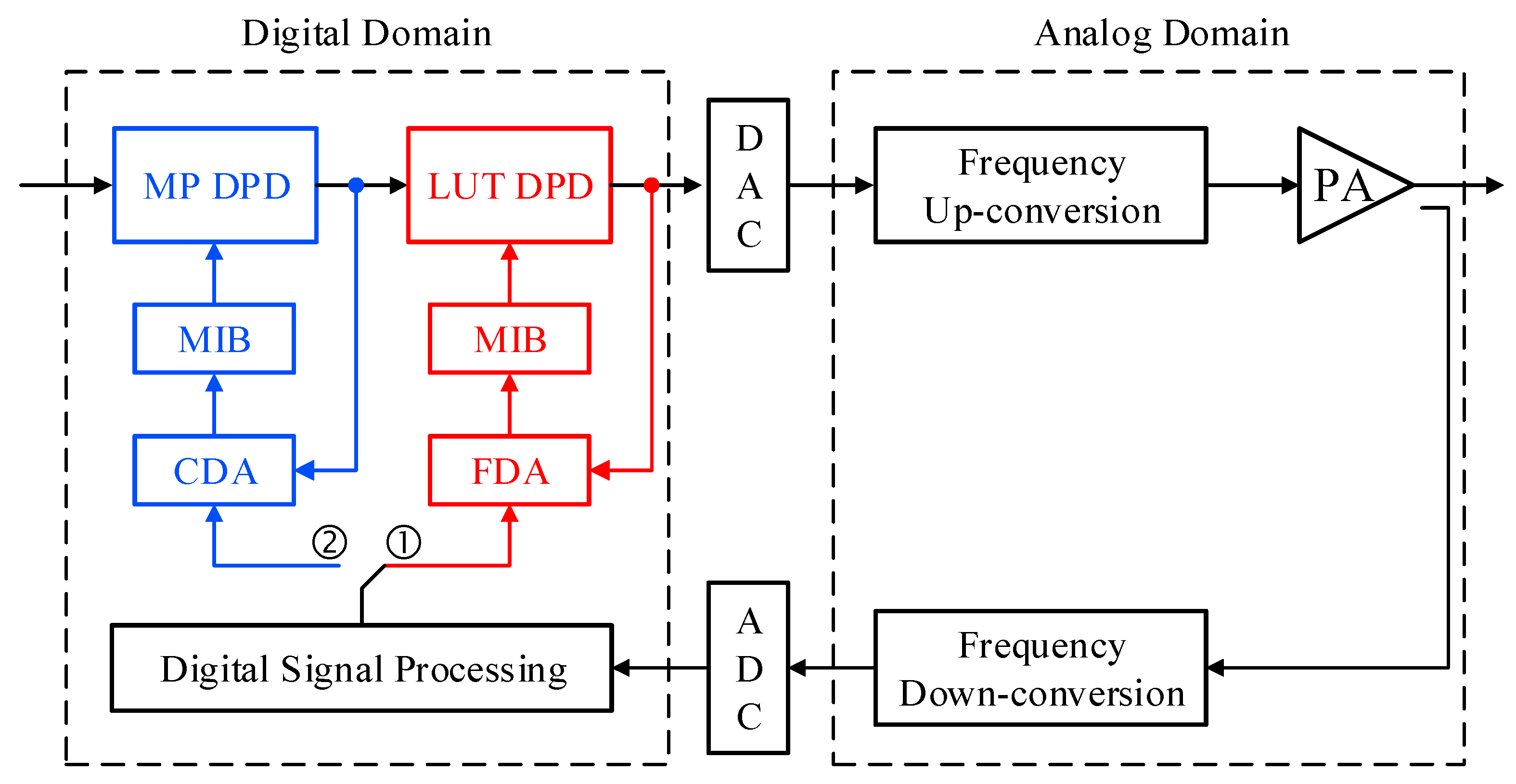
In this paper, a sequential digital predistorter (S-DPD) system built using a twin nonlinear two-box (TNTB) predistorter able to achieve an extended correction bandwidth is proposed. The proposed predistorter system contrasts with previously reported TNTB predistorters [23,24] in several major aspects. Firstly, the predistortion function is identified in two sequential steps: two consecutive characterizations using reduced feedback bandwidth are used to derive the static predistortion sub-function implemented as a memoryless look-up table, and then the dynamic nonlinear sub-function implemented as a memory polynomial (MP). Secondly, the S-DPD system does not require any hardware overhead to implement the predistortion function. Indeed, only a single standard feedback loop is needed to derive the predistortion function since the sequential characterization is performed within the digital domain. Thirdly, the computational complexity associated with the proposed S-DPD system is reduced by adopting a coarse delay estimation and alignment algorithm while calculating the coefficients of the memory polynomial sub-function of the predistorter and alleviating the need for data de-embedding when identifying the second predistortion sub-function. Finally, extended correction bandwidth is achieved without the need for offline characterization of the static nonlinearity of the device under test (DUT). In fact, the use of static predistortion function derived from offline measurements (as reported in prior work) represents a significant drawback for several reasons. First, there is a need to pre-calculate a large set of memoryless predistortion functions that would take into account the variation of the operating conditions of the PA mainly due to the variations of the average power as well as the signal statistics. Secondly, the PA is likely to experience long-term drifts of the bias point, operating temperature, etc. While some of these changes (such as bias drifts) are unobservable, their impact on the DPD performance translates into a degradation of the adjacent channel leakage ratio. Taking into account the signal variations as well as the operating conditions, variations will require an unrealistically large set of LUTs to be pre-built offline. Moreover, from an implementation point of view, there is a need to determine which of the memoryless LUTs needs to be applied as the static predistortion function. This requires an additional processing block that would select the most suitable LUT predistorter based on the knowledge of the signal characteristics, operating conditions, etc.
Accordingly, the novelty in the proposed predistorter is related to the following aspects:
  • First, the predistortion function is performed in a sequential manner through two distinct characterization steps.
  • Second, a single characterization hardware loop is used for both characterization steps.
  • Third, a relaxed sampling rate is used in the feedback path for acquisition of the power amplifier’s output.
  • Fourth, the computational complexity overhead due to the proposed technique is minimized through the use of coarse delay alignment when identifying the second predistortion sub-function.
  • Fifth, the use of sequential identification process minimizes the computational complexity associated with the signal reconstruction to a simple re-sampling operation.
The above-mentioned five aspects cohesively allow for substantial improvements in digital predistortion systems that makes it possible to achieve satisfactory linearity performance over a correction bandwidth much larger than the observation bandwidth of the feedback path without the computational and hardware complexity drawbacks observed in previously reported work.
In Section 2, the proposed S-DPD system is introduced and thoroughly discussed. In Section 3, the S-DPD system is applied for the linearization of an inverse Class-F power amplifier prototype. The computational complexity reduction through coarse delay alignment is investigated in Section 4. The conclusions are reported in Section 5.

2. Sequential Digital Predistortion Using Under-Sampled Feedback Signals

2.1. Frequency Domain Analysis of Power Amplifier’s Nonlinear Distortions

Nonlinear distortions such as those exhibited by power amplifiers are commonly characterized by the spectrum regrowth they cause through intermodulation and harmonic distortions. Two-tones along with a simplified polynomial model of the nonlinear PA are often used to illustrate this basic concept. Harmonic distortions can be eliminated through filtering, and hence are not considered problematic when linearizing power amplifiers. Conversely, intermodulation distortions are located too close to the in-band signal to be filtered. Therefore, the synthesis of digital predistortion function is usually based on the observation of the amplifier’s output signal over a bandwidth that spans up to five times the bandwidth of the input signal. This serves to guarantee the inclusion of the third and fifth order intermodulation distortions caused by the power amplifier. However, a closer look using a multi-tone signal can clearly illustrate that the in-band frequency range contains significant information about the nonlinearity of the power amplifier. To illustrate this aspect, a five-tone input signal is considered for this analysis. This time domain input signal x i n t is given by:
x i n t = i = 1 5 A i × cos 2 π f i t + ϕ i ,
where A i , f i , and ϕ i represent the amplitude, frequency and initial phase of the i t h tone.
The power amplifier’s nonlinearity can be modeled by a simple nonlinear polynomial function, such that
x o u t t = k = 1 N α k x i n k t ,
where x o u t t is the amplifier’s output signal, N is the nonlinearity order, and α k are the model coefficients.
The analytical derivation of the amplifier’s output signal x o u t for a third order nonlinear model, and the analysis of its frequency content show the presence of 145 components including 15 components around DC, 80 components in the in-band region corresponding to the input signal’s frequency range (including intermodulation distortions), and 15 and 35 components in the frequency ranges corresponding to the second and third order harmonics, respectively.
As a numerical example, let us consider the case of a five-tone signal where the tones’ frequencies are uniformly spaced between 890 MHz and 910 MHz. Figure 1 depicts the number of terms at each frequency component around the original transmit band. Most importantly, this figure shows that the in-band frequency range has a significantly larger number of terms when compared to the intermodulation range. Therefore, it can be anticipated that the reduction of the observation bandwidth in the feedback path of the digital predistortion system can lead to a fairly accurate representation of the amplifier’s nonlinear behavior.

2.2. Proposed Sequential Digital Predistortion

Two-box based digital predistorters have been widely used for the linearization of wideband power amplifiers exhibiting strong memory effects [9]. In fact, these models typically result in better performance than their single-box counterpart while requiring a lower number of coefficients. In conventional two-box models, the static and the dynamic nonlinearity functions are derived concurrently from a single set of measurements. The flow chart of such process is depicted in Figure 2. First, the input signal is applied to the PA, and the corresponding output signal is acquired. The input and output baseband complex waveforms are then used to perform accurate delay estimation and alignment with a sub-sample delay resolution. This is essential to cancel out the propagation delay between the input and output waveforms, and accurately derive the instantaneous gain of the amplifier. Following this delay estimation and alignment step, the time-aligned input and output waveforms are used to identify the look-up table corresponding to the memoryless predistortion sub-function. Later, and depending on the structure of the two-box network, the signals at the input and output of the remaining predistortion sub-function are generated. This data de-embedding process is then followed by the identification of the memory polynomial predistortion sub-function. This step completes the identification process of the predistortion function. The obtained DPD is then applied to linearize the device under test. Depending on the performance of the synthesized digital predistortion, the update of the predistortion function may be triggered (if the DPD performance does not meet the requirements) or not (if the DPD performance meets the requirements).
The proposed S-DPD uses the reverse TNTB structure introduced in [23] along with an enhanced identification approach that allows for the effective use of under-sampled feedback signals. The TNTB predistorter architecture, presented in Figure 3, is made of a memory polynomial function followed by an LUT function. As per the conventional DPD identification process depicted in Figure 2, only one characterization is performed. This characterization, labelled as Characterization #1 in Figure 3, is used to synthesize the two sub-functions of the DPD model by applying the identification process of Figure 2.
In the proposed approach, two characterization steps are performed. As shown in Figure 3, the first characterization step includes only the power amplifier, and uses the input and output baseband waveforms of the power amplifier to synthesize the LUT predistortion function. During the synthesis of the LUT DPD, accurate delay estimation is used. However, a reduced sampling rate is adopted in the feedback path. In fact, even though such reduction will lead to sub-optimal and slightly inaccurate memoryless DPD sub-function, the resulting residual distortions will be addressed and compensated for during the second characterization step. In this second characterization step, the system to be characterized is made of the LUT DPD as well as the PA (as shown in Figure 3). This system has a mildly nonlinear behavior since the LUT was designed with the objective of reducing the PA distortions. Therefore, reduced sampling rate in the feedback path will not introduce any significant errors since the bandwidth of the signal at the output of the partly linearized system (LUT DPD + PA) is expected to be significantly narrower than that of the PA alone. During the second characterization step, coarse delay estimation and alignment is performed. This implies that the delay resolution will be equal to the sampling period of the signals. This reduces the complexity associated with accurate delay estimation and alignment. Furthermore, the step related to the data de-embedding needed in the conventional identification approach is avoided in the proposed system and is replaced by the second characterization. Hence, the sequential characterization approach eliminates the data de-embedding step, and allows for the use of reduced sampling rates in the feedback path without causing a loss of performance for the proposed DPD as it will be demonstrated through the experimental validation section. The flow chart summarizing the identification process of the proposed sequential DPD system is presented in Figure 4.
From an implementation point of view, the proposed sequential DPD does not involve any additional circuitry in the analog domain. The detailed block diagram presented in Figure 5 shows that a single feedback loop is used for both characterization steps. This feedback path provides access to the power amplifier’s output signal. The output of the power amplifier is down-converted and then digitized using an analog to digital converter (ADC) operating at lower sampling rate. The signal at the output of the ADC is fed to a digital signal-processing block which mainly implements the up-sampling of the acquired PA output signal in order to have consistent sampling rates between the input and output waveforms being fed to the delay alignment blocks. The identification of the LUT-based DPD sub-function includes a fine delay alignment (FDA) block. Conversely, a coarse delay alignment (CDA) block is used for the identification of the memory polynomial DPD sub-function. From a hardware perspective, the proposed DPD is identical to conventional DPDs in the sense that only a single feedback path is required. However, this feedback path operates at reduced sampling rate in the proposed DPD. In the digital domain, the proposed DPD includes two loops. The first loop (shown in red color in Figure 5) is used to identify the LUT DPD function. It includes a fine-delay alignment block (FDA) followed by a model identification block (MIB) which calculates the model coefficients or in this case the LUT entries. In the second loop (shown in blue color in Figure 5), a coarse delay alignment (CDA) is first performed, then the coefficients of the MP function are identified using the MIB block. Depending on which predistortion sub-function is being identified, the output of the digital signal processing block is channeled to position ① or ②. The output of the LUT DPD is fed into a digital to analog converter (DAC) which generates the analog signal to be up-converted by the frequency up-conversion stage before being applied at the input of the power amplifier. In the scheme depicted in Figure 5, the DPD update is performed using the signal to be transmitted and does not require any synthetic test signal. Hence, it can be performed online while the PA is operating and does not require any down time.
Compared to conventional identification techniques of two-box models, the proposed sequential DPD eliminates the need for data de-embedding needed to calculate the memory polynomial function, but requires an additional delay alignment step. However, the complexity of this step is reduced by using a coarse delay alignment algorithm. In fact, it was shown in [25] that the identification of static nonlinear distortions requires sub-sample delay resolution for satisfactory modelling accuracy, while the identification of the memory polynomial function is robust to delay misalignment. Therefore, in the proposed DPD, when the static nonlinear function is being identified, a sub-sample accurate delay estimation and alignment algorithm is used. Conversely, when the memory polynomial function is identified, a coarse-delay alignment algorithm with a one-sample resolution will be used. This will contribute to reducing the computational complexity associated with the identification of the memory polynomial sub-function in the proposed S-DPD.

3. Performance Assessment of the Proposed Digital Predistortion System

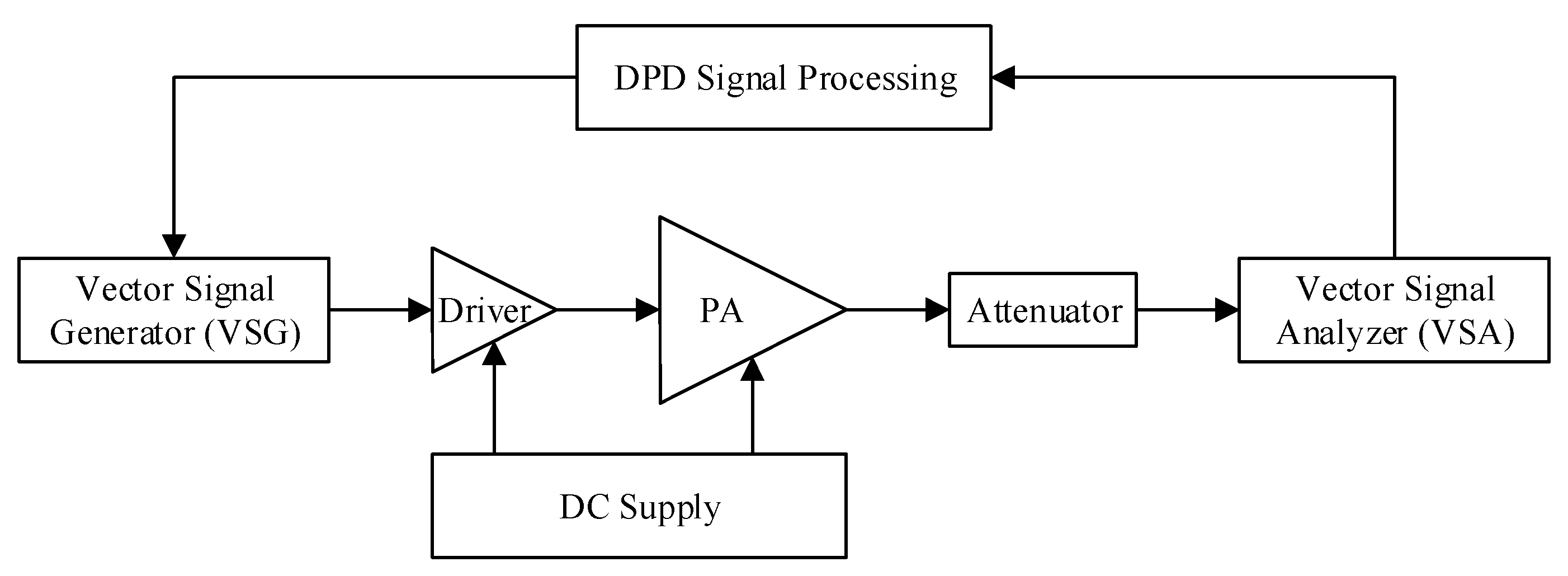
For the experimental validation of the proposed DPD, an inverse Class-F power amplifier operating around 900 MHz was used. The functional block diagram of the experimental setup is reported in 
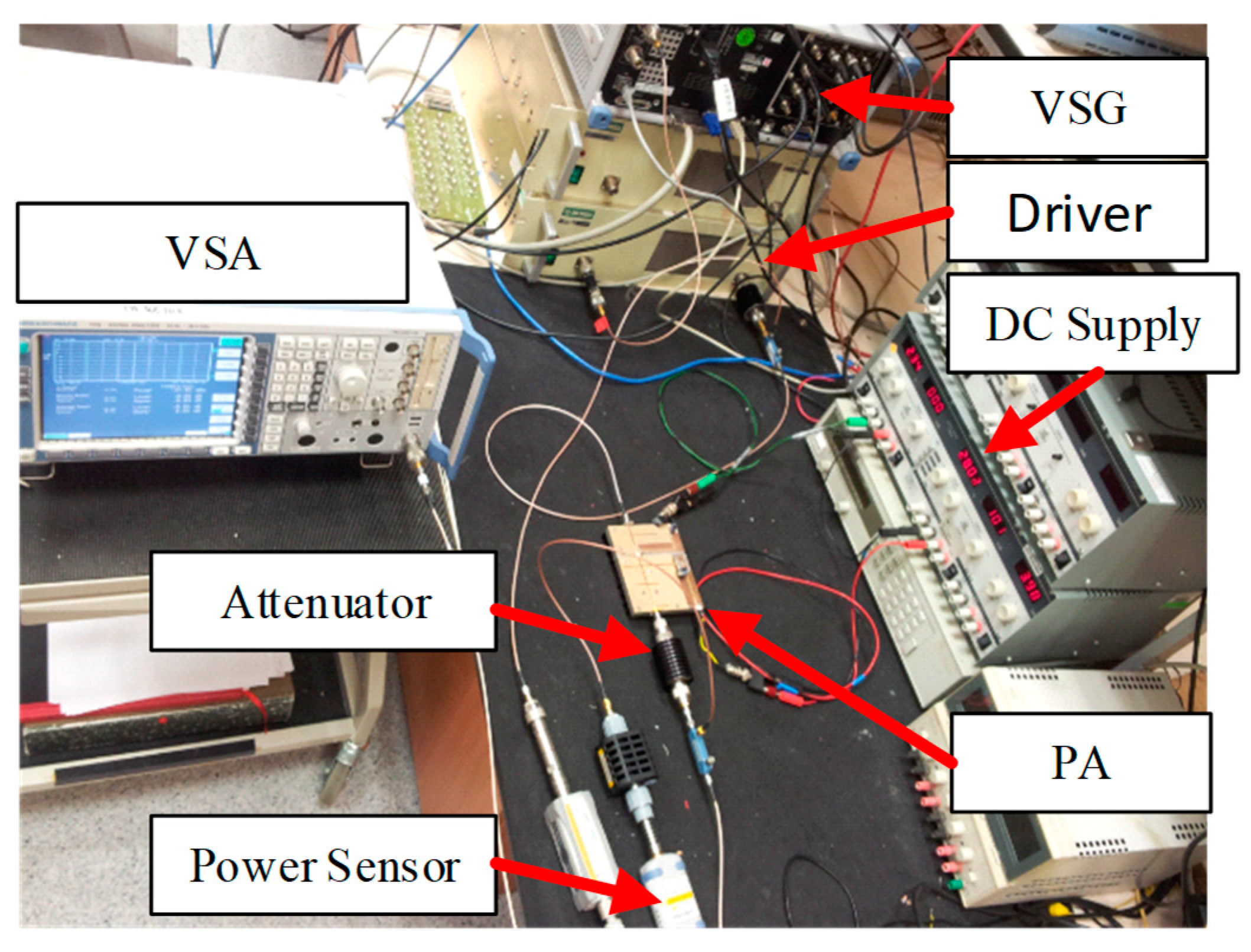
Figure 6. The DPD signal processing unit includes the functionalities related to time delay alignment, DPD function identification and predistortion of the input signal. The baseband digital waveform at the output of the DPD signal processing unit is fed into the vector signal generator (VSG) which implements the digital to analog conversion and the frequency up-conversion. The signal at the output of the VSG is pre-amplified using a driver before being applied at the input of the main power amplifier. The signal at the output of the power amplifier is first attenuated and then fed into the vector signal analyzer (VSA). The VSA performs the frequency down-conversion, the analog to digital conversion, and the demodulation of the signal. The resulting digital waveform corresponding to the PA’s output signal is used by the DPD signal processing block to synthesize the predistortion function. A photograph of the experimental setup is presented in Figure 7.
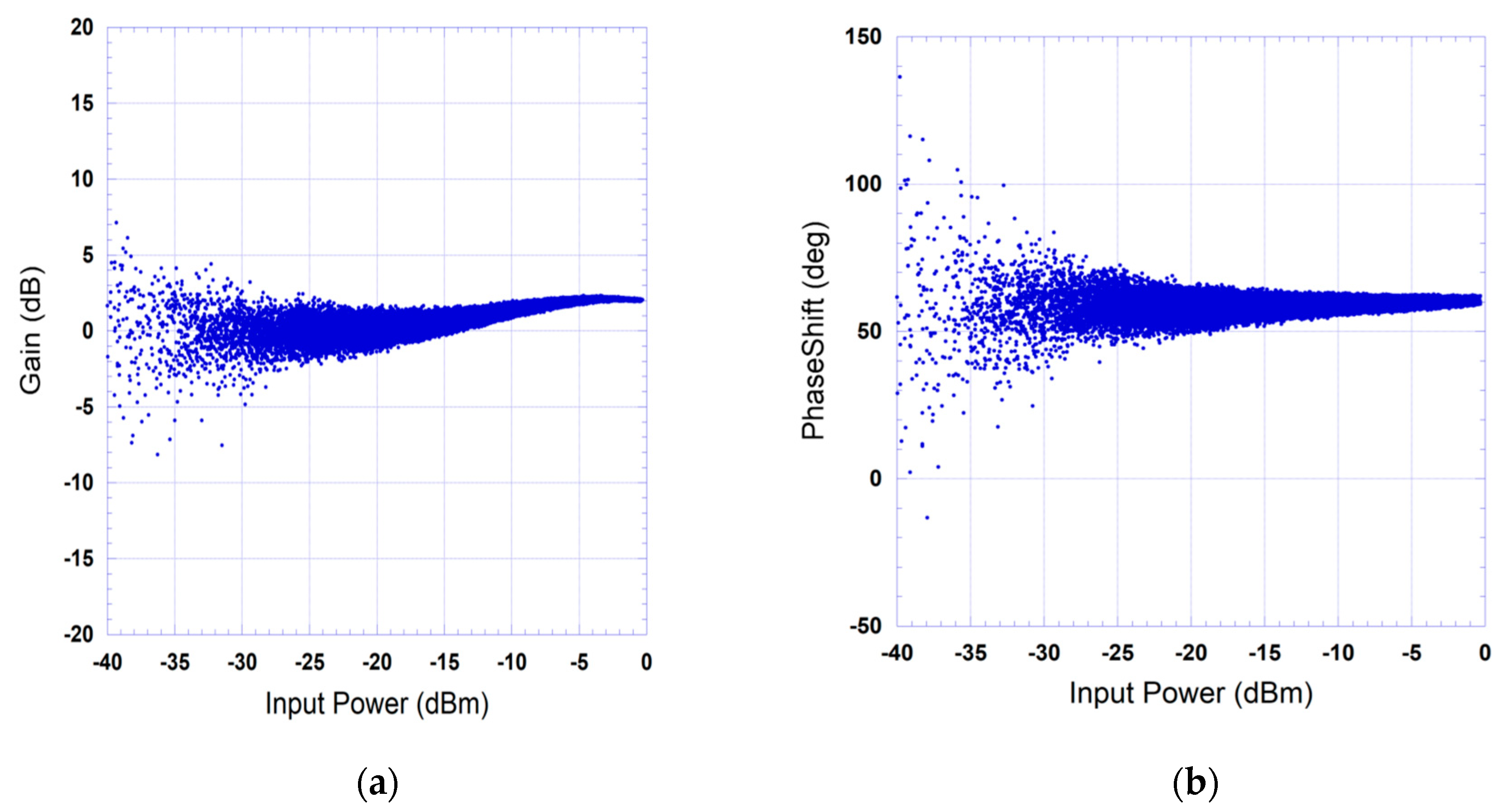
The PA was driven by a test signal having a bandwidth of 20 MHz. This bandwidth is largest that can be handled by the available experimental setup. The output signal was acquired at various sampling rates using the vector signal analyzer. The sampling rates used were 100 MSa/s, 50 MSa/s, 40 MSa/s, 30 MSa/s and 25 MSa/s. The in-phase and quadrature components of the baseband input signal I i n , Q i n and the in-phase and quadrature components of the baseband output signal I o u t , Q o u t were used to compute the instantaneous complex gain of the device under test and derive its AM/AM (amplitude-modulation to amplitude-modulation) and AM/PM (amplitude-modulation to phase-modulation) characteristics. The AM/AM and AM/PM characteristics represent the magnitude and the phase of the complex instantaneous gain, respectively. The measured AM/AM and AM/PM characteristics of the device under test derived from the 100 MSa/s sampling rate data acquisition are presented in Figure 8.
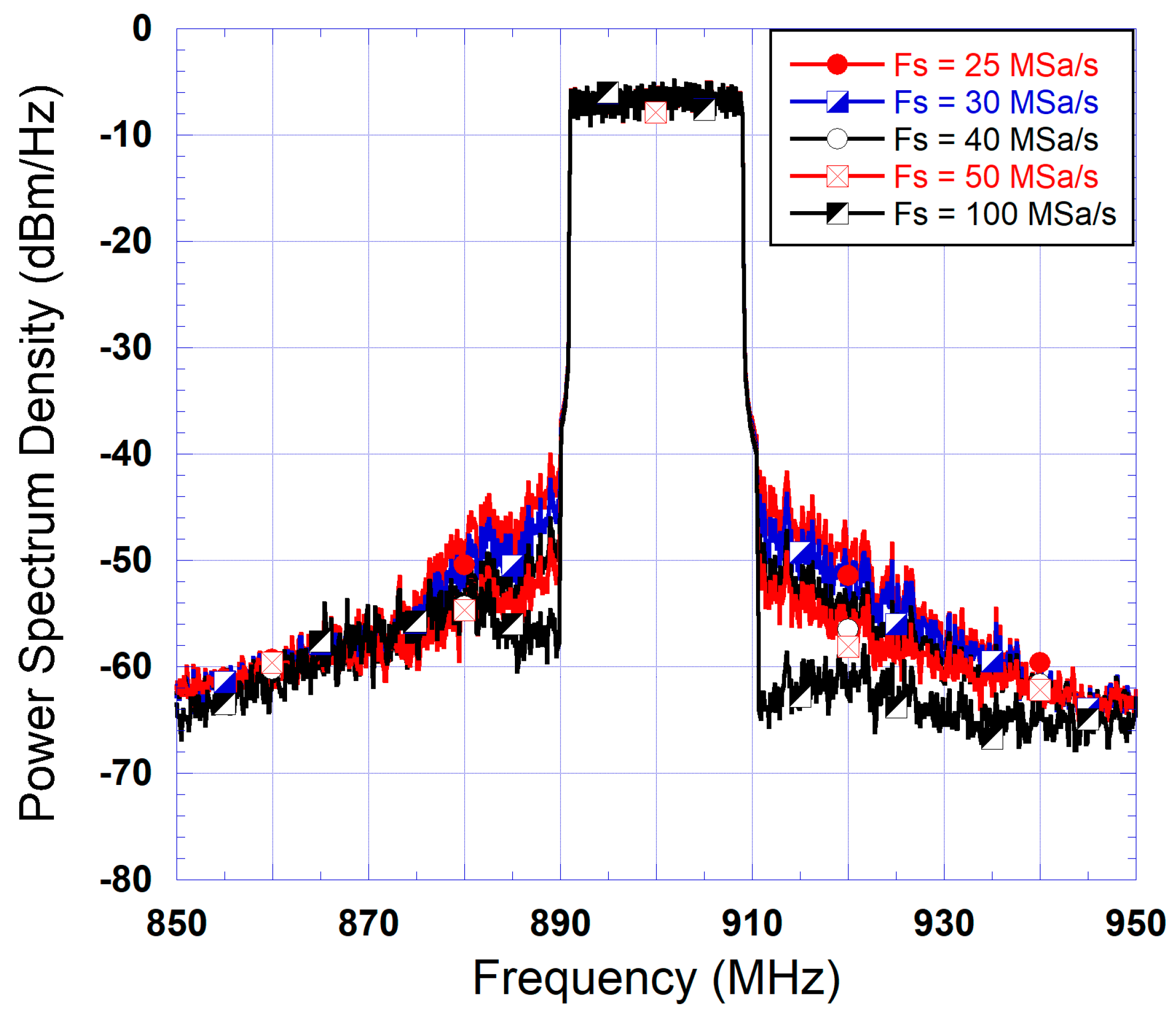
Then, the five acquisitions of the DUT’s output signal were performed using sampling rates of 100 MSa/s, 50 MSa/s, 40 MSa/s, 30 MSa/s and 25 MSa/s. In these tests, since the input waveform has a sampling rate of 100 MSa/s, acquisitions performed at lower sampling rates required the use of a resampling step in order to up-sample the acquired output signal to the same 100 MSa/s rate as the input signal. This resampling step is accomplished before performing the time delay estimation and alignment as well as the predistortion function synthesis. From each of the five acquired output signals, a memoryless look-up table was built. All predistorters were derived from the measured input and output data using the same exponentially weighted moving average algorithm for the LUT DPD synthesis. These LUT-based DPDs were then used to linearize the power amplifier when driven by the 20 MHz input signal. The spectra obtained at the output of the linearized power amplifier are reported in Figure 9 for all the memoryless predistorters along with the output spectra without linearization. This figure shows that the LUT derived from the measured output signal at 100 MSa/s leads to the best linearization performance. However, residual distortions can be seen in this spectrum. This is expected since the DUT exhibits memory effects, and therefore a memoryless DPD will not be able to fully compensate for the DUT’s distortions.
Moreover, considering the spectra (of Figure 9) corresponding to DPDs derived from lower sampling rates, additional performance degradation is observed. This performance deterioration is more pronounced as the sampling rate decreases. This is anticipated since a more accurate reconstruction of the output signal waveform sampled at 100 MSa/s will translate into a more accurate model of the DUT, and hence a more optimal memoryless LUT. However, even though the performances of the DPDs derived from low-sampling-rate data acquisitions are not as good as the one derived from 100 MSa/s measurement, they lead to noticeable spectrum regrowth cancellation ranging from 10 dB to 20 dB for the 25 MSa/s and the 50 MSa/s data acquisitions, respectively. More importantly, this spectrum regrowth cancellation reduces the bandwidth of the signal at the output of the device under test, which will reduce the impact of the limited observation bandwidth on the performance of the DPD. Accordingly, the use of the low-sampling-rate data acquisitions for the synthesis of the second predistortion sub-function (the memory polynomial block) is anticipated to further enhance the capabilities of the predistorter.
The last step in the validation of the proposed S-DPD system is to assess the performance of the complete two-box DPD for each value of the sampling rates used in the signal observation path. First, the benchmark data corresponding to a data acquisition at sampling rate of 100 MSa/s was used to determine the required dimensions for the memory polynomial block of the two-box DPD. The memory polynomial predistortion function is given by
x o u t _ M P n = k = 1 K m = 0 M a k m x i n _ M P n m x i n _ M P n m k 1 ,
where x i n _ M P and x o u t _ M P are the input and the output of the MP function, respectively. a k m are the complex-valued model coefficients. K and M represent the memory polynomial’s nonlinearity order and memory depth, respectively.
For the considered DUT, it was found that the MP sub-function needed to have a nonlinearity order K = 7 and a memory depth M = 5 . This setting (nonlinearity order and memory depth) of the MP sub-function was kept the same for all MP sub-functions derived from the under-sampled output waveforms. For each acquisition, a new set of coefficients was calculated.
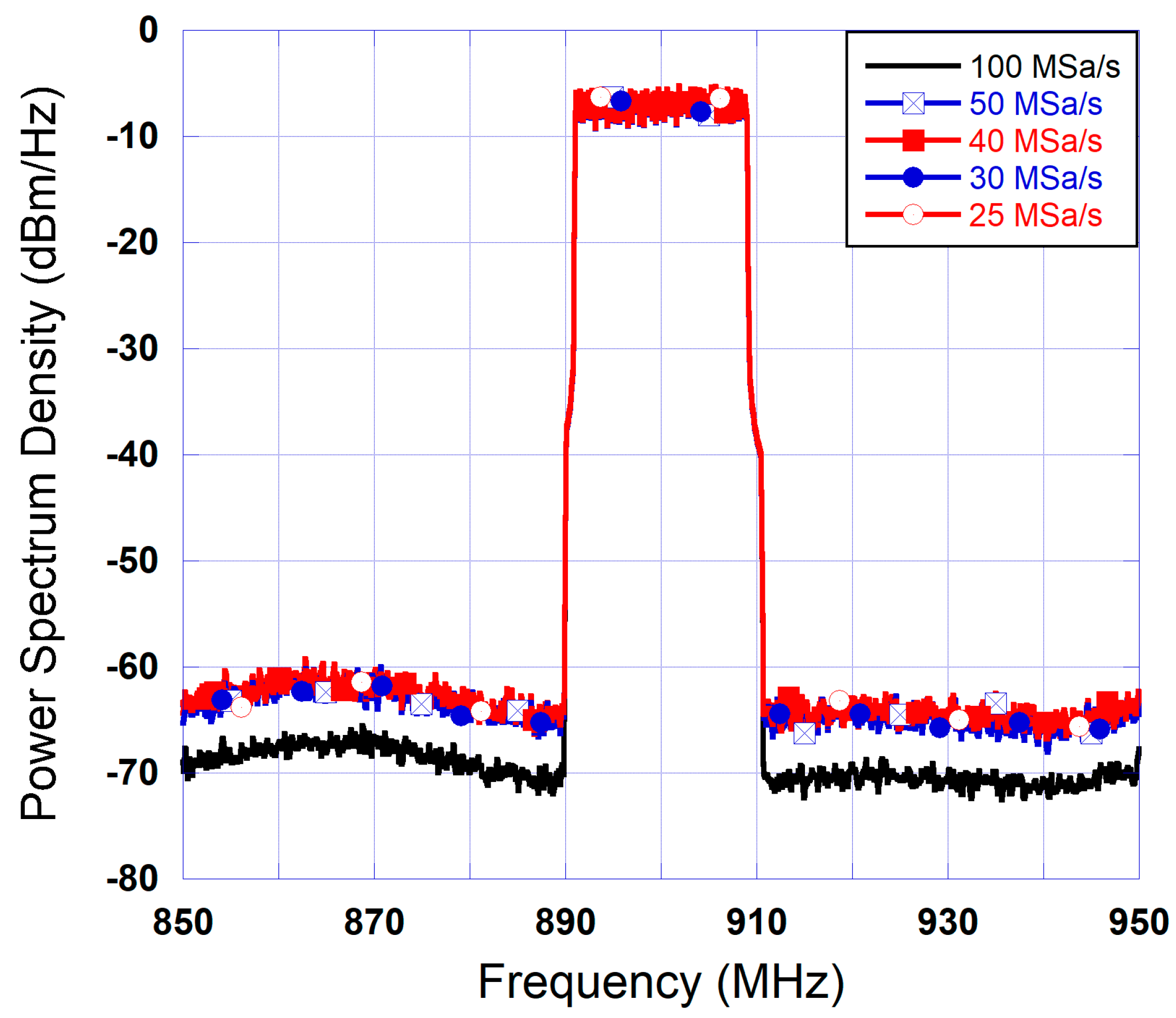
For the 25 MSa/s data acquisition, the signal at the output of the amplifier linearized using the memoryless LUT derived from the same sampling rate was used along with the LUT’s input signal to build the memory polynomial sub-function of the predistorter. This sub-function, also derived from data acquired at 25 MSa/s, aims at linearizing the cascade made of the LUT predistorter and the power amplifier. The same test was repeated for the 30 MSa/s, 40 MSa/s and 50 MSa/s acquisitions as well as the 100 MSa/s benchmark. The spectra obtained at the output of the power amplifier following the use of the cascade made of the memory polynomial and the LUT DPDs are reported in Figure 10 for all considered sampling rates. This figure clearly shows that the use of the proposed sequential DPD technique can result in excellent linearization without performance deteriorations as the sampling rate is reduced by a factor of four from 100 MSa/s to 25 MSa/s. This is mainly due to the fact that despite the imperfections of the LUT DPD, it still reduces the bandwidth of the partly linearized output signal, and the fact that the MP DPD is derived to linearize the cascade made of the LUT and DUT in a second iteration.

4. Complexity Reduction through Coarse Delay Alignment

In order to further reduce the computational complexity associated with the identification of the memory polynomial coefficients, coarse delay alignment algorithm was used to time-align the input and output waveforms prior to the identification of the memory polynomial predistortion function. The main reason is that fine-delay alignment is a computationally extensive process. In fact, delay alignment with a resolution T s R where T s is the sampling period of the two signals to be time-aligned typically requires up-sampling the signals by a factor R , performing delay estimation and alignment often using cross-correlation technique, and then down-sampling the waveforms by a factor of R back to their original sampling rate. Therefore, using a delay resolution equal to the signal’s sampling rate R = 1 will eliminate the need for the signal up-sampling and down-sampling processes in the delay estimation and alignment and hence reduce the computational complexity associated with this process.
For the experimental validation of the coarse delay alignment, the identification of the LUT sub-function was not modified, and a fine delay alignment was used in that step. However, a coarse delay alignment algorithm was adopted for the MP DPD identification.
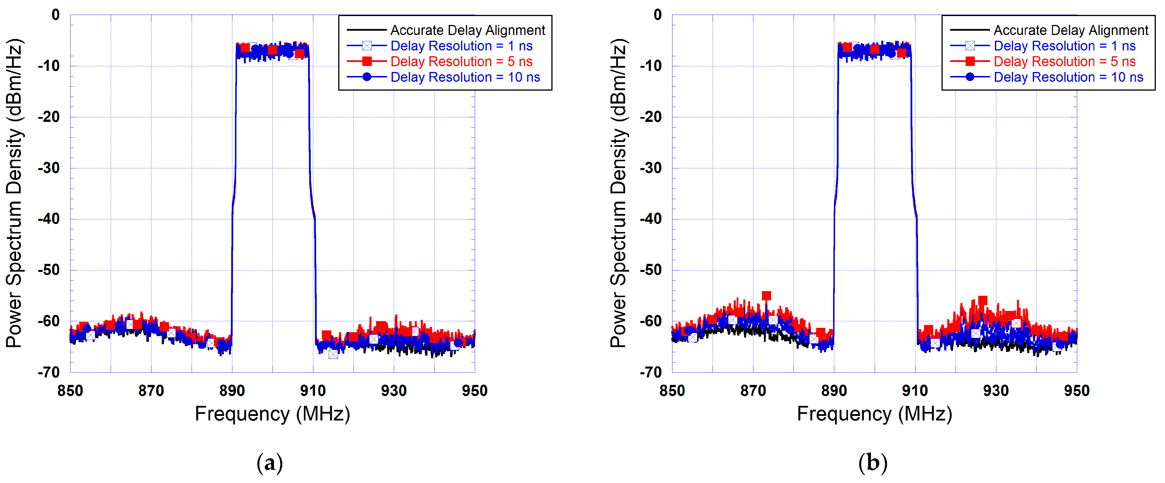
To assess the impact of the delay misalignment caused by the limited delay resolution of the coarse alignment, three delay resolutions were considered. These are 1 ns, 5 ns and 10 ns, which correspond to 0.1 T s , 0.5 T s and T s , where T s is the sampling period of the 100 MSa/s input signal. Moreover, a reference memory polynomial DPD derived from accurate delay estimation and alignment was used as a benchmark.
The effects of the coarse delay alignment are depicted in the plots of Figure 11. For conciseness, this figure only includes the results corresponding to 50 MSa/s and 25 MSa/s rates in the feedback path. Comparable results have been obtained for the 40 MSa/s and 30 MSa/s cases. The results of Figure 11 show that the impact of limited delay resolution is slightly more pronounced for the signal acquisition performed at 25 MSa/s than the one performed at 50 MSa/s. Most importantly, these results clearly demonstrate that a delay resolution of up to 10 ns, which corresponds to one sample, does not have a significant impact on the sequential DPD performance. Hence, delay estimation and alignment for the MP DPD identification can be performed with low complexity algorithms that do not require sub-sample resolution without compromising the performance of the S-DPD.

5. Conclusions

In this paper, a sequential DPD architecture was proposed and experimentally validated. Compared to conventional predistortion systems, the proposed DPD reduces the complexity of the feedback path hardware by using reduced sampling rates for the acquisition of the PA output signal. Moreover, the computational complexity of the proposed predistorter is reduced by using a coarse delay resolution for the identification of the memory polynomial DPD. The two-step sequential characterization and predistortion function synthesis does not add any hardware overhead, reduces the sampling rate in the feedback path, eliminates the need for signal de-embedding required for the identification of the MP DPD sub-function, and alleviates the computational complexity of the delay estimation and alignment. Experimental results show that the proposed DPD can successfully linearize a PA driven by a 20 MHz test signal while operating the feedback path at 25 MSa/s, and using a coarse delay alignment resolution. Future work can investigate the suitability of the proposed architecture for other two-box digital predistortion functions, and the possibility of extending the complexity reduction to the transmit path.

Author Contributions

Conceptualization, O.H. and S.B.; methodology, M.A. and R.A.; validation, M.A.; formal analysis, M.A. and R.A.; writing—original draft preparation, M.A. and R.A.; writing—review and editing, O.H. and S.B.; supervision, O.H.; project administration, O.H.; funding acquisition, O.H. All authors have read and agreed to the published version of the manuscript.

Funding

This research was funded by the Research Office at the American University of Sharjah under Grant FRG20-M-E85. The work in this paper was supported, in part, by the Open Access Program from the American University of Sharjah.

Data Availability Statement

The data used for this research work are not publicly available.

Conflicts of Interest

The authors declare no conflicts of interest. The funders had no role in the design of the study; in the collection, analyses, or interpretation of data; in the writing of the manuscript; or in the decision to publish the results.

References

  1. Kakkavas, G.; Diamanti, M.; Stamou, A.; Karyotis, V.; Bouali, F.; Pinola, J.; Apilo, O.; Papavassiliou, S.; Moessner, K. Design, Development, and Evaluation of 5G-Enabled Vehicular Services: The 5G-HEART Perspective. Sensors 2022, 22, 426. [Google Scholar] [CrossRef]
  2. Devi, D.H.; Duraisamy, K.; Armghan, A.; Alsharari, M.; Aliqab, K.; Sorathiya, V.; Das, S.; Rashid, N. 5G Technology in Healthcare and Wearable Devices: A Review. Sensors 2023, 23, 2519. [Google Scholar] [CrossRef]
  3. Mazhar, T.; Malik, M.A.; Haq, I.; Rozeela, I.; Ullah, I.; Khan, M.A.; Adhikari, D.; Ben Othman, M.T.; Hamam, H. The Role of ML, AI and 5G Technology in Smart Energy and Smart Building Management. Electronics 2022, 11, 3960. [Google Scholar] [CrossRef]
  4. Tengg, A.; Stolz, M.; Hillebrand, J. A Feasibility Study of a Traffic Supervision System Based on 5G Communication. Sensors 2022, 22, 6798. [Google Scholar] [CrossRef] [PubMed]
  5. Franchi, F.; Marotta, A.; Rinaldi, C.; Graziosi, F.; Fratocchi, L.; Parisse, M. What Can 5G Do For Public Safety? Structural Health Monitoring and Earthquake Early Warning Scenarios. Sensors 2022, 22, 3020. [Google Scholar] [CrossRef]
  6. Volk, M.; Sterle, J. 5G Experimentation for Public Safety: Technologies, Facilities, and Use Cases. IEEE Access 2021, 9, 41184–41217. [Google Scholar] [CrossRef]
  7. Guevara, L.; Auat Cheein, F. The Role of 5G Technologies: Challenges in Smart Cities and Intelligent Transportation Systems. Sustainability 2020, 12, 6469. [Google Scholar] [CrossRef]
  8. Banafaa, M.; Pepeoglu, O.; Shayea, I.; Alhammadi, A.; Shamsan, Z.A.; Razaz, M.A.; Alsagabi, M.; Al-Sowayan, S. A Comprehensive Survey on 5G-and-Beyond Networks with UAVs: Applications, Emerging Technologies, Regulatory Aspects, Research Trends and Challenges. IEEE Access 2024, 12, 7786–7826. [Google Scholar] [CrossRef]
  9. Ghannouchi, F.M.; Hammi, O. Behavioral Modeling and Predistortion. IEEE Microw. Mag. 2009, 10, 52–64. [Google Scholar] [CrossRef]
  10. Somasundaram, G.; Mayeda, J.C.; Sweeney, C.; Lie, D.Y.C.; Lopez, J. Effective Digital Predistortion (DPD) on a Broadband Millimeter-Wave GaN Power Amplifier Using LTE 64-QAM Waveforms. Electronics 2023, 12, 2869. [Google Scholar] [CrossRef]
  11. Zhong, T.; Peng, J.; He, S.; You, F.; Guo, J.; Wang, X.; Tang, Y.; He, G. Low Computational Complexity Delay Estimation Algorithm for Digital Predistortion. IEEE Trans. Circuits Syst. II Exp. Briefs. 2024; in press. [Google Scholar] [CrossRef]
  12. Li, B.; Hu, X.; Kan, N.; Wang, W.; Ghannouchi, F.M. Computationally Stable Low Sampling Rate Digital Predistortion for Non-Terrestrial Networks. IEEE Trans. Broadcast. 2024, 70, 325–333. [Google Scholar] [CrossRef]
  13. Ali, A.; Hammi, O. Bandwidth, Power and Carrier Configuration Resilient Neural Networks Digital Predistorter. IEEE Access 2023, 11, 63126–63135. [Google Scholar] [CrossRef]
  14. Muškatirović-Zekić, T.; Nešković, N.; Budimir, D. Efficient Neural Network DPD Architecture for Hybrid Beamforming mMIMO. Electronics 2023, 12, 597. [Google Scholar] [CrossRef]
  15. Hadi, M.U.; Danyaro, K.U.; AlQushaibi, A.; Qureshi, R.; Alam, T. Digital Predistortion Based Experimental Evaluation of Optimized Recurrent Neural Network for 5G Analog Radio Over Fiber Links. IEEE Access 2024, 12, 19765–19777. [Google Scholar] [CrossRef]
  16. Yu, Y.; Yu, L.; Zhai, J.; Chen, P.; Yu, C. Dynamic Activation Digital Predistortion of RF Power Amplifiers for 6G Dynamic Spectrum Aggregation Applications. IEEE Trans. Microw. Theroy Techn. 2024; in press. [Google Scholar] [CrossRef]
  17. Hammi, O.; Boumaiza, S.; Jaidane-Sidane, M.; Ghannouchi, F.M. Digital Subband Filtering Predistorter Architecture for Wireless Transmitters. IEEE Trans. Microw. Theroy Techn. 2005, 53, 1643–1652. [Google Scholar] [CrossRef]
  18. Kumar, A.; Shipra; Rawat, M. Bandlimited DPD Adapted APD for 5G Communication. IEEE Trans. Circuits Syst. II Exp. Briefs. 2023, 70, 496–500. [Google Scholar] [CrossRef]
  19. Yu, C.; Guan, L.; Zhu, E.; Zhu, A. Band-Limited Volterra Series-Based Digital Predistortion for Wideband RF Power Amplifiers. IEEE Trans. Microw. Theroy Techn. 2012, 60, 4198–4208. [Google Scholar] [CrossRef]
  20. Ma, Y.; Yamao, Y.; Akaiwa, Y.; Ishibashi, K. Wideband Digital Predistortion Using Spectral Extrapolation of Band-Limited Feedback Signals. IEEE Trans. Circuits Syst. I Reg. Pap. 2014, 61, 2088–2097. [Google Scholar] [CrossRef]
  21. Liu, Y.; Yan, J.J.; Dabag, H.T.; Asbeck, P.M. Novel Technique for Wideband Digital Predistortion of Power Amplifiers with an Under-Sampling ADC. IEEE Trans. Microw. Theroy Techn. 2014, 62, 2604–2617. [Google Scholar] [CrossRef]
  22. Bensmida, S.; Hammi, O.; Kwan, A.; Sharawi, M.S.; Morris, K.; Ghannouchi, F.M. Extending the Characterization Bandwidth of Dynamic Nonlinear Transmitters with Application to Digital Predistortion. IEEE Trans. Microw. Theroy Techn. 2016, 64, 2640–2651. [Google Scholar] [CrossRef]
  23. Hammi, O.; Kwan, A.; Bensmida, S.; Morris, K.; Ghannouchi, F.M. A Digital Predistortion System with Extended Correction Bandwidth with Application to LTE-A Nonlinear Power Amplifiers. IEEE Trans. Circuits Syst. I Reg. Pap. 2014, 61, 3487–3495. [Google Scholar] [CrossRef]
  24. Hammi, O.; Ghannouchi, F.M. Twin Nonlinear Two-Box Models for Power Amplifiers and Transmitters Exhibiting Memory Effects with Application to Digital Predistortion. IEEE Microw. Wirel. Compon. Lett. 2009, 19, 530–532. [Google Scholar] [CrossRef]
  25. Abdelnaby, M.; Hammi, O. Comparative Analysis of Single-Box and Two-Box RF Power Amplifiers’ Behavioral Models Sensitivity to Delay Misalignment. In Proceedings of the International Conference Electrical, Electronics, and System Engineering, Kuala Lumpur, Malaysia, 8–9 November 2018. [Google Scholar] [CrossRef]
Figure 1. Frequency content of amplifier’s input and output signal for a five-tone input signal and a third order polynomial model: (a) input signal; (b) output signal.
Smartcities 07 00032 g001
Figure 2. Flow chart of conventional two-box DPD identification process.
Smartcities 07 00032 g002
Figure 3. Simplified reverse TNTB predistorter block diagram.
Smartcities 07 00032 g003
Figure 4. Flow chart of proposed two-box S-DPD identification process. (Solid boxes refer to steps that are also in the conventional approach. Dashed boxes refer to steps specific to the proposed S-DPD).
Smartcities 07 00032 g004
Figure 5. Proposed sequential DPD system.
Smartcities 07 00032 g005
Figure 6. Functional block diagram of the experimental setup.
Smartcities 07 00032 g006
Figure 7. Photograph of the experimental setup.
Smartcities 07 00032 g007
Figure 8. Measured instantaneous gain characteristics of the device under test: (a) AM/AM characteristic; (b) AM/PM characteristic.
Smartcities 07 00032 g008
Figure 9. Spectra at the output of the amplifier following partial linearization using LUT–DPD.
Smartcities 07 00032 g009
Figure 10. Spectra at the output of the amplifier linearized using the sequential DPD for various feedback sampling rates.
Smartcities 07 00032 g010
Figure 11. Spectra at the output of the amplifier linearized using the sequential DPD for various delay resolutions: (a) feedback signal sampled at 50 MSa/s; (b) feedback signal sampled at 25 MSa/s.
Smartcities 07 00032 g011
Disclaimer/Publisher’s Note: The statements, opinions and data contained in all publications are solely those of the individual author(s) and contributor(s) and not of MDPI and/or the editor(s). MDPI and/or the editor(s) disclaim responsibility for any injury to people or property resulting from any ideas, methods, instructions or products referred to in the content.

