
Design of Digital Constrained Linear Least-Squares Multiple-Resonator-Based Harmonic Filtering


Abstract
:1. Introduction
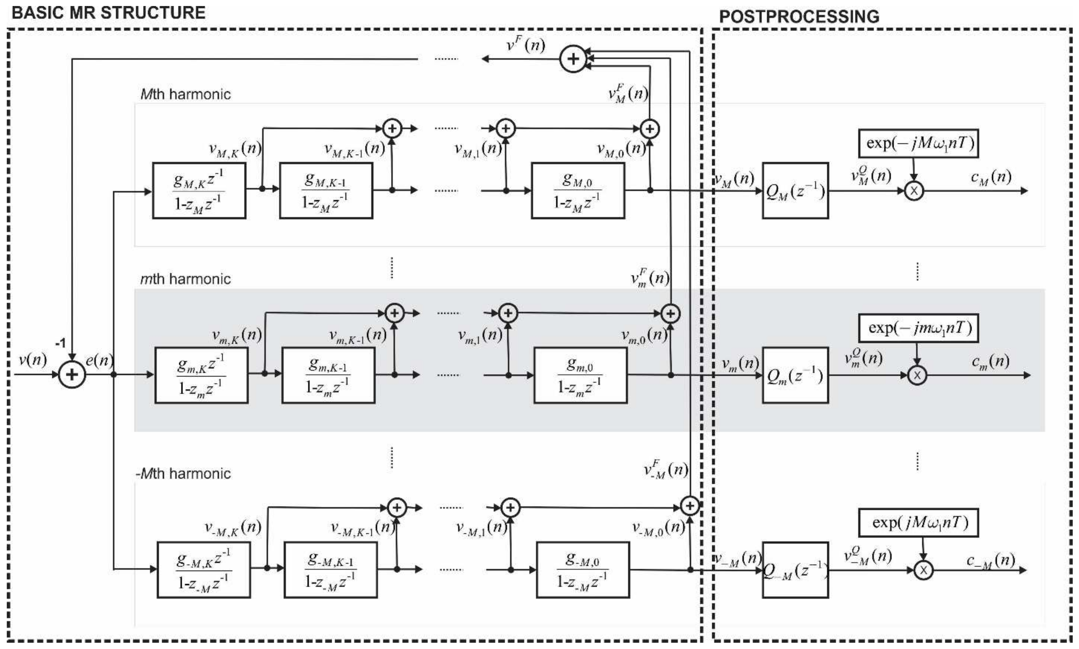
2. Design Method
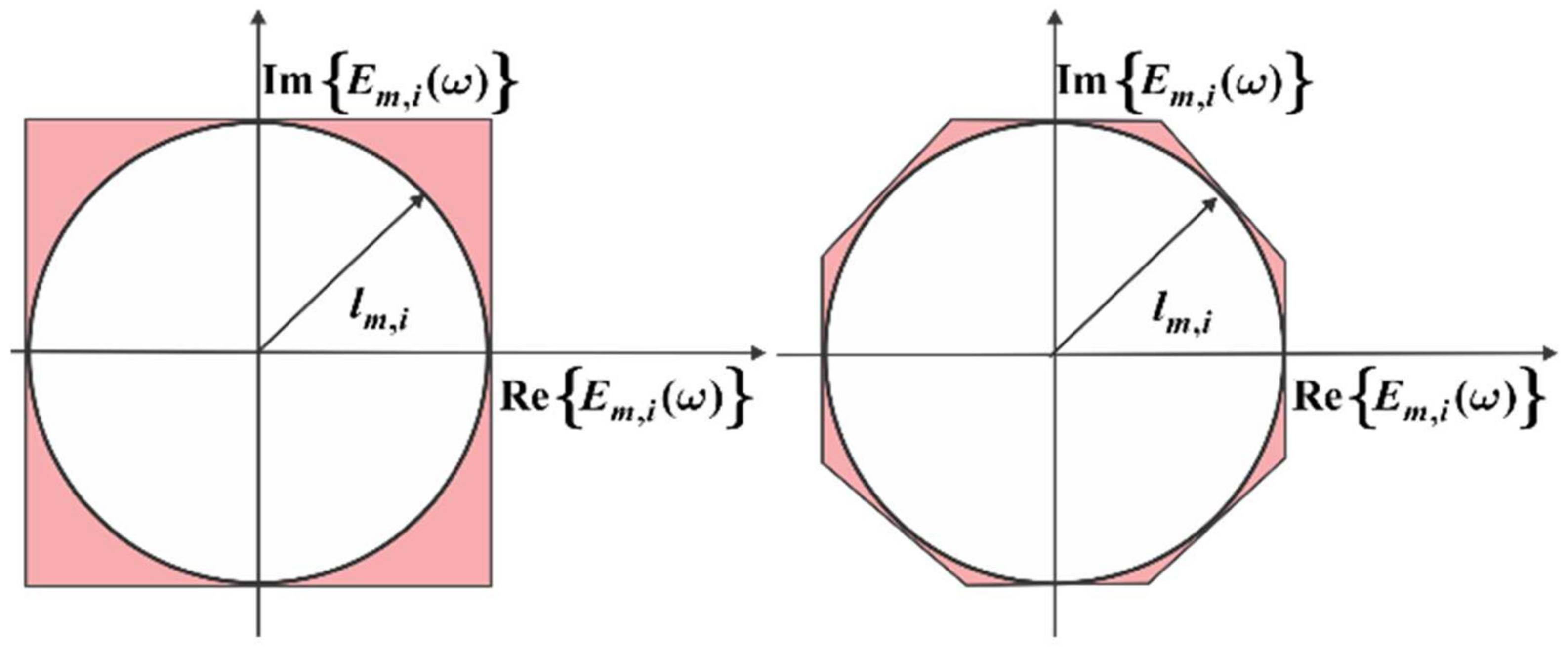
2.1. Total Vector Gradient (TVG) Calculation
2.2. Constrainting Conditions Linearization
2.3. Sum of Squares Calculation
2.4. Constrained Linear Least-Squares (CLLS) Model
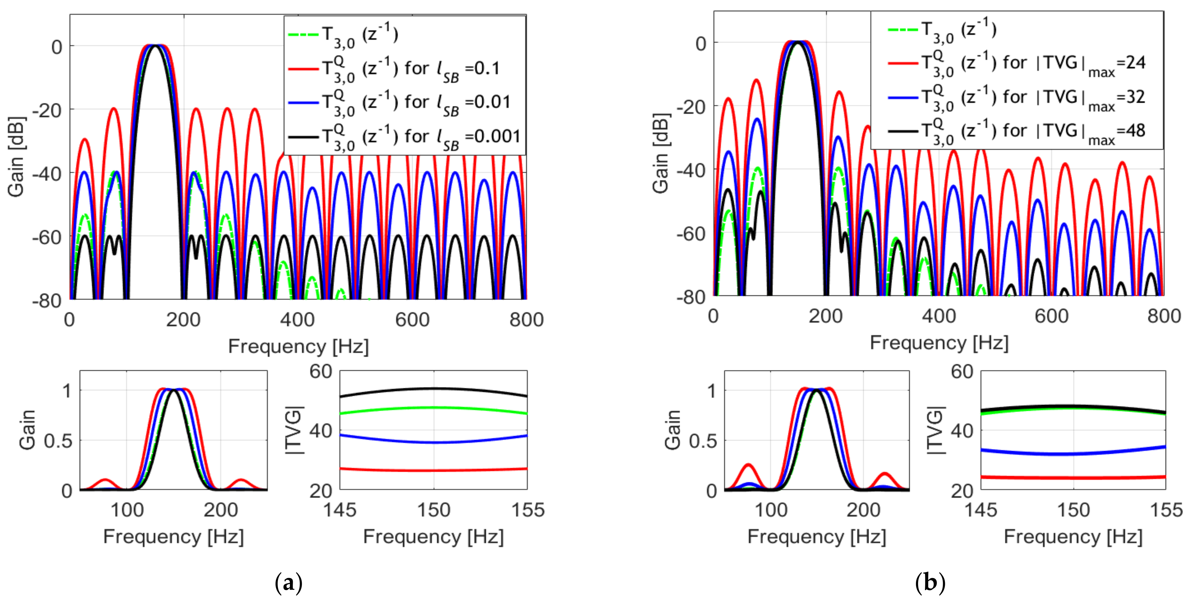
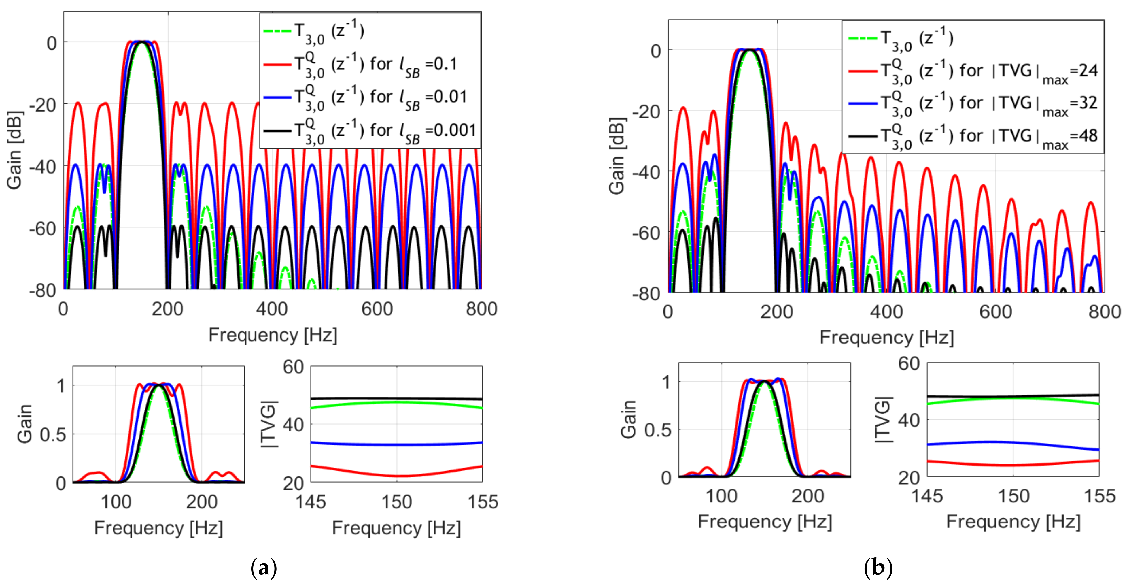
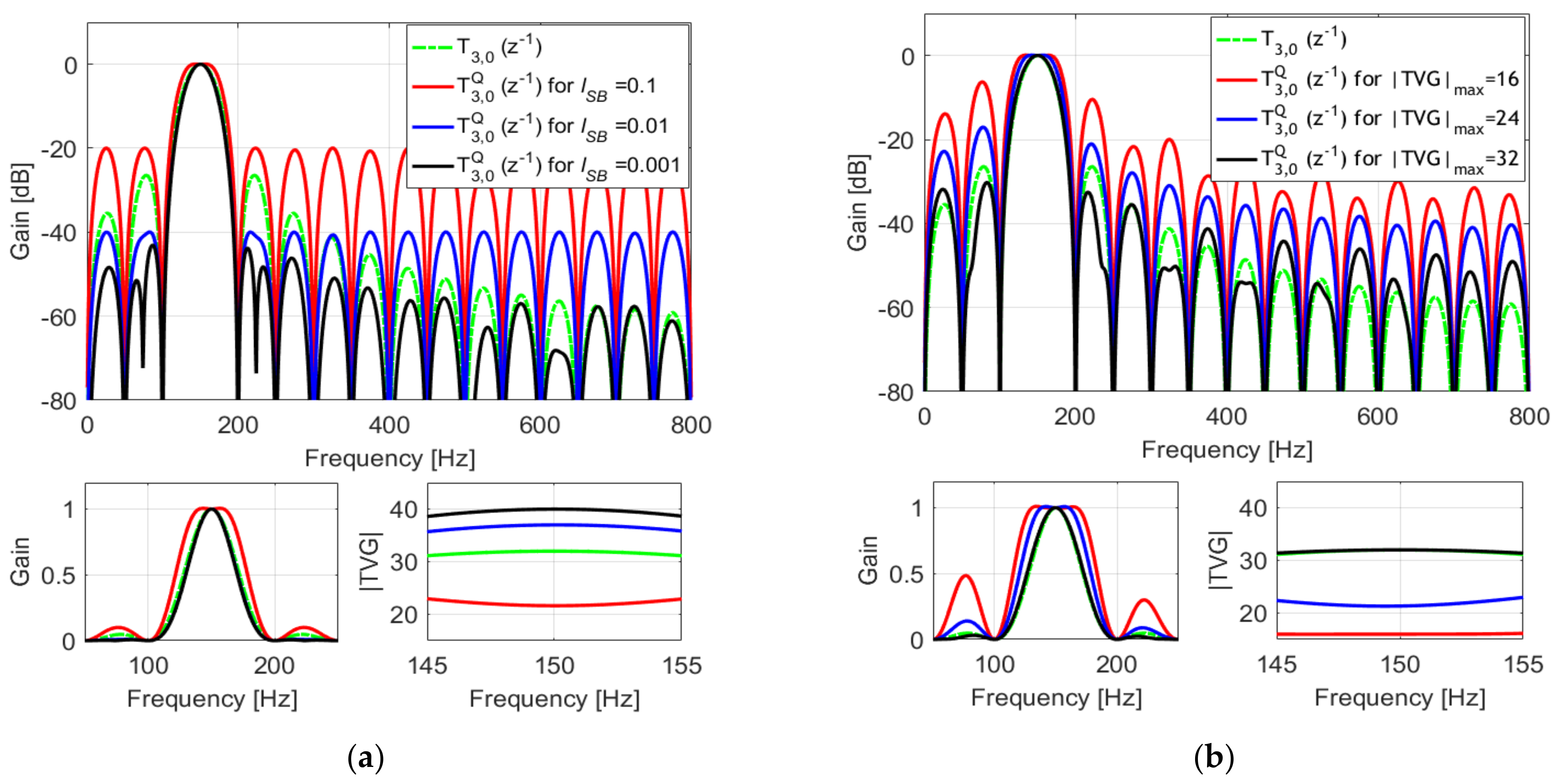
3. Design Example
4. Simulation Results
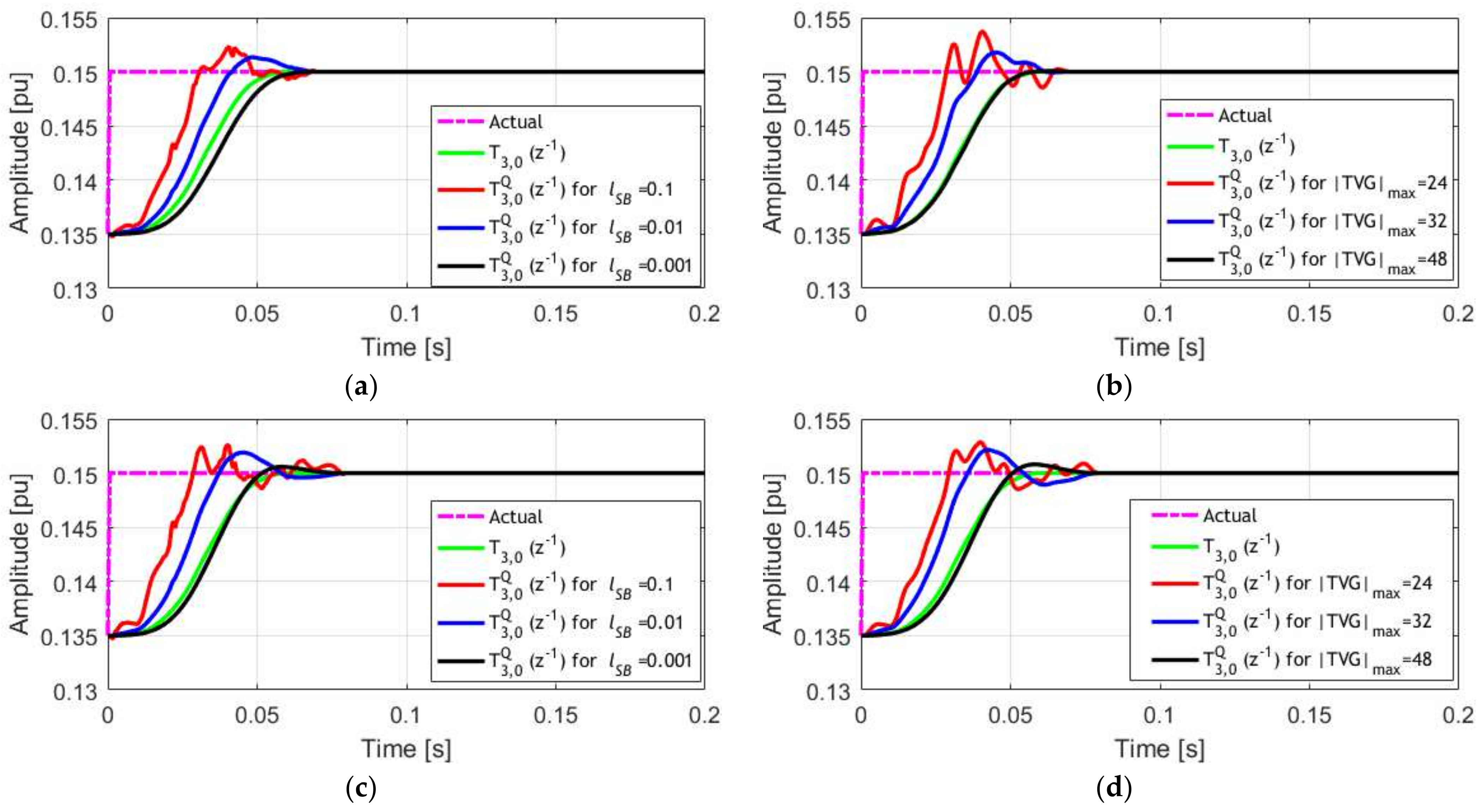
4.1. Amplitude Modulated Signal
4.2. Amplitude Step Signal
5. Conclusions
Author Contributions
Funding
Institutional Review Board Statement
Informed Consent Statement
Data Availability Statement
Conflicts of Interest
References
- Nehorai, A.; Porat, B. Adaptive Comb Filtering for Harmonic Signal Enhancement. IEEE Trans. Acoust. Speech Signal Process. 1986, 34, 1124–1138. [Google Scholar] [CrossRef]
- Widrow, B.; Williams, C.S.; Glover, J.R.; McCool, J.M.; Hearn, R.H.; Zeidler, J.R.; Kaunitz, J.; Dong, E.; Goodlin, R.C. Adaptive Noise Cancelling: Principles and Applications. Proc. IEEE 1975, 63, 1692–1716. [Google Scholar] [CrossRef]
- Pariente, M.; Cornell, S.; Deleforge, A.; Vincent, E. Filterbank Design for End-to-End Speech Separation. In Proceedings of the ICASSP, IEEE International Conference on Acoustics, Speech and Signal Processing, Barcelona, Spain, 4–8 May 2020. [Google Scholar]
- Li, Q.; Chen, W.G.; He, C.; Malvar, H.S. Design of Oversampled DFT Modulated Filter Banks Optimized for Acoustic Echo Cancellation. In Proceedings of the ICASSP, IEEE International Conference on Acoustics, Speech and Signal Processing, Barcelona, Spain, 4–8 May 2009. [Google Scholar]
- Jin, W.; Liu, X.; Scordilis, M.S.; Han, L. Speech Enhancement Using Harmonic Emphasis and Adaptive Comb Filtering. IEEE Trans. Audio Speech Lang. Process. 2010, 18, 356–368. [Google Scholar] [CrossRef]
- Russo, E. Tools for Interactive Audio Signal Analysis Based on Sliding DFT. In Proceedings of the 12th International Conference on Digital Audio Effects, DAFx, Como, Italy, 28 July 2009. [Google Scholar]
- Lazzarini, V.; Lysaght, T.; Timoney, J. Spectral Signal Processing in Csound 5. In Proceedings of the International Computer Music Conference, ICMC, New Orleans, LA, USA, 6–11 November 2006. [Google Scholar]
- Harčarik, T.; Bocko, J.; Masláková, K. Frequency Analysis of Acoustic Signal Using the Fast Fourier Transformation in MATLAB. Procedia Eng. 2012, 48, 199–204. [Google Scholar] [CrossRef]
- Elshamy, S.; Madhu, N.; Tirry, W.; Fingscheidt, T. Two-Stage Speech Enhancement with Manipulation of the Cepstral Excitation. In Proceedings of the 2017 Hands-Free Speech Communications and Microphone Arrays, HSCMA 2017, San Francisco, CA, USA, 1–3 March 2017. [Google Scholar]
- Selvi, T.; Pragatheeswaran, J. Efficient Speech Enhancement Technique by Exploiting the Harmonic Structure of Voiced Segments. In Proceedings of the International Conference on Recent Trends in Information Technology, ICRTIT, Chennai, India, 3–5 June 2011. [Google Scholar]
- Hendriks, R.C.; Jensen, J.; Heusdens, R. Noise Tracking Using DFT Domain Subspace Decompositions. IEEE Trans. Audio Speech Lang. Process. 2008, 16, 541–553. [Google Scholar] [CrossRef] [Green Version]
- Hendriks, R.C.; Heusdens, R.; Jensen, J.; Kjems, U. Low Complexity DFT-Domain Noise PSD Tracking Using High-Resolution Periodograms. Eurasip J. Adv. Signal Process. 2009, 2009, 925870. [Google Scholar] [CrossRef] [Green Version]
- Kartik, C. Understanding Audio Data, Fourier Transform, FFT and Spectrogram Features for a Speech Recognition System. Available online: https://towardsdatascience.com/understanding-audio-data-fourier-transform-fft-spectrogram-and-speech-recognition-a4072d228520 (accessed on 24 October 2021).
- Wung, J.; Giacobello, D.; Atkins, J. Robust Acoustic Echo Cancellation in the Short-Time Fourier Transform Domain Using Adaptive Crossband Filters. In Proceedings of the ICASSP, IEEE International Conference on Acoustics, Speech and Signal Processing, Florence, Italy, 4–9 May 2014. [Google Scholar]
- Aminifar, F.; Fotuhi-Firuzabad, M.; Safdarian, A.; Davoudi, A.; Shahidehpour, M. Synchrophasor Measurement Technology in Power Systems: Panorama and State-of-the-Art. IEEE Access 2014, 2, 1607–1628. [Google Scholar] [CrossRef]
- Jain, A.; Samantaray, S.R.; Geoffroy, L.; Kamwa, I. Synchrophasors Data Analytics Framework for Power Grid Control and Dynamic Stability Monitoring. Eng. Technol. Ref. 2016, 1–22. [Google Scholar] [CrossRef]
- Chakir, M.; Kamwa, I.; le Huy, H. Extended C37.118.1 PMU Algorithms for Joint Tracking of Fundamental and Harmonic Phasors in Stressed Power Systems and Microgrids. IEEE Trans. Power Deliv. 2014, 29, 1465–1480. [Google Scholar] [CrossRef]
- Zecevic, Z.; Krstajic, B. Dynamic Harmonic Phasor Estimation by Adaptive Taylor-Based Bandpass Filter. IEEE Trans. Instrum. Meas. 2020, 70, 1–9. [Google Scholar] [CrossRef]
- Duda, K.; Zielinski, T.P.; Bien, A.; Barczentewicz, S.H. Harmonic Phasor Estimation with Flat-Top FIR Filter. IEEE Trans. Instrum. Meas. 2020, 69, 2039–2047. [Google Scholar] [CrossRef]
- Chen, L.; Zhao, W.; Xie, X.; Zhao, D.; Huang, S. Harmonic Phasor Estimation Based on Frequency-Domain Sampling Theorem. IEEE Trans. Instrum. Meas. 2021, 70, 1–10. [Google Scholar] [CrossRef]
- Bertocco, M.; Frigo, G.; Narduzzi, C.; Tramarin, F. Resolution Enhancement by Compressive Sensing in Power Quality and Phasor Measurement. IEEE Trans. Instrum. Meas. 2014, 63, 2358–2367. [Google Scholar] [CrossRef]
- IEC/IEEE 60255-118-1:2018. IEC IEEE/IEC International Standard—Measuring Relays and Protection Equipment—Part 118-1: Synchrophasor for Power Systems—Measurements; IEEE: Piscataway, NJ, USA, 2018. [Google Scholar]
- Messina, F.; Marchi, P.; Vega, L.R.; Galarza, C.G.; Laiz, H. A Novel Modular Positive-Sequence Synchrophasor Estimation Algorithm for PMUs. IEEE Trans. Instrum. Meas. 2017, 66, 1164–1175. [Google Scholar] [CrossRef]
- Razo-Hernandez, J.R.; Valtierra-Rodriguez, M.; Granados-Lieberman, D.; Tapia-Tinoco, G.; Rodriguez-Rodriguez, J.R. A Phasor Estimation Algorithm Based on Hilbert Transform for P-Class PMUs. Adv. Electr. Comput. Eng. 2018, 18, 97–105. [Google Scholar] [CrossRef]
- Tosato, P.; Macii, D.; Luiso, M.; Brunelli, D.; Gallo, D.; Landi, C. A Tuned Lightweight Estimation Algorithm for Low-Cost Phasor Measurement Units. IEEE Trans. Instrum. Meas. 2018, 67, 1047–1057. [Google Scholar] [CrossRef]
- Belega, D.; MacIi, D.; Petri, D. Fast Synchrophasor Estimation by Means of Frequency-Domain and Time-Domain Algorithms. IEEE Trans. Instrum. Meas. 2014, 63, 388–401. [Google Scholar] [CrossRef]
- Coletta, G.; Vaccaro, A.; Villacci, D. A Review of the Enabling Methodologies for PMUs-Based Dynamic Thermal Rating of Power Transmission Lines. Electr. Power Syst. Res. 2017, 152, 257–270. [Google Scholar] [CrossRef]
- Affijulla, S.; Tripathy, P. Development of Phasor Estimation Algorithm for P-Class PMU Suitable in Protection Applications. IEEE Trans. Smart Grid 2018, 9, 1250–1260. [Google Scholar] [CrossRef]
- Roscoe, A.J.; Dickerson, B.; Martin, K.E. Filter Design Masks for C37.118.1a-Compliant Frequency-Tracking and Fixed-Filter M-Class Phasor Measurement Units. IEEE Trans. Instrum. Meas. 2015, 64, 2096–2107. [Google Scholar] [CrossRef] [Green Version]
- Abdolkhalig, A.; Zivanovic, R. Phasor Measurement Based on IEC 61850-9-2 and Kalman-Filtering. Measurement 2014, 50, 126–134. [Google Scholar] [CrossRef]
- Razo-Hernandez, J.R.; Mejia-Barron, A.; Granados-Lieberman, D.; Valtierra-Rodriguez, M.; Gomez-Aguilar, J.F. A New Phasor Estimator for Pmu Applications: P Class and M Class. J. Mod. Power Syst. Clean Energy 2020, 8, 55–66. [Google Scholar] [CrossRef]
- Platas-Garza, M.A.; de La Serna, J.A.O. Dynamic Harmonic Analysis through Taylor-Fourier Transform. IEEE Trans. Instrum. Meas. 2011, 60, 804–813. [Google Scholar] [CrossRef]
- Kusljevic, M.D.; Tomic, J.J. Multiple-Resonator-Based Power System Taylor-Fourier Harmonic Analysis. IEEE Trans. Instrum. Meas. 2015, 64, 554–563. [Google Scholar] [CrossRef]
- Kusljevic, M.D.; Tomic, J.J.; Poljak, P.D. Maximally Flat-Frequency-Response Multiple-Resonator-Based Harmonic Analysis. IEEE Trans. Instrum. Meas. 2017, 66, 3387–3398. [Google Scholar] [CrossRef]
- Kušljević, M.D.; Tomić, J.J.; Poljak, P.D. Constrained-Group-Delay-Optimized Multiple-Resonator-Based Harmonic Analysis. Teh. Vjesn. 2021, 28, 1244–1252. [Google Scholar] [CrossRef]
- Kušljević, M.D. Multiple-Resonator-Based Harmonic Analysis. In Proceedings of the 2nd International Conference on Electrical, Electronic and Computing Engineering IcETRAN, Silver Lake, Serbia, 8–11 June 2015; p. MLI1.1.1-12. [Google Scholar]
- Tomic, J.J.; Poljak, P.D.; Kušljevic, M.D. Frequency-Response-Controlled Multiple-Resonator-Based Harmonic Analysis. Electron. Lett. 2018, 54, 202–204. [Google Scholar] [CrossRef]
- Messina, F.; Vega, L.R.; Marchi, P.; Galarza, C.G. Optimal Differentiator Filter Banks for PMUs and Their Feasibility Limits. IEEE Trans. Instrum. Meas. 2017, 66, 2948–2956. [Google Scholar] [CrossRef]
- Kušljević, M.D.; Tomić, J.J.; Poljak, P.D. On Multiple-Resonator-Based Implementation of IEC/IEEE Standard P-Class Compliant PMUs. Energies 2021, 14, 198. [Google Scholar] [CrossRef]


Publisher’s Note: MDPI stays neutral with regard to jurisdictional claims in published maps and institutional affiliations. |
© 2022 by the authors. Licensee MDPI, Basel, Switzerland. This article is an open access article distributed under the terms and conditions of the Creative Commons Attribution (CC BY) license (https://creativecommons.org/licenses/by/4.0/).
Share and Cite
Kušljević, M.D.; Vujičić, V.V. Design of Digital Constrained Linear Least-Squares Multiple-Resonator-Based Harmonic Filtering. Acoustics 2022, 4, 111-122. https://doi.org/10.3390/acoustics4010008
Kušljević MD, Vujičić VV. Design of Digital Constrained Linear Least-Squares Multiple-Resonator-Based Harmonic Filtering. Acoustics. 2022; 4(1):111-122. https://doi.org/10.3390/acoustics4010008
Chicago/Turabian StyleKušljević, Miodrag D., and Vladimir V. Vujičić. 2022. "Design of Digital Constrained Linear Least-Squares Multiple-Resonator-Based Harmonic Filtering" Acoustics 4, no. 1: 111-122. https://doi.org/10.3390/acoustics4010008