1. Introduction
In the audio industry, composite plates have been used to fabricate panel-form speakers for sound radiation. In general, a panel-form speaker is much thinner than a conventional cone-type speaker. Due to its thinness, the panel-form speaker has the advantage to be used in the device, which may have limited space for installing an audio system. For instance, consumer electronics such as TVs, computers, tablets, cell phones, etc., are getting much thinner so that panel-form speakers become more suitable for installation than the conventional cone type speakers. However, the use of a plate as a sound radiator has a shortcoming. Regarding stiffness, a plate is generally weaker than a cone structure. Therefore, a sound radiation plate is more susceptible to produce major dips or drops on the sound pressure level (SPL) curve than a cone-shape diaphragm. Regarding sound radiation fidelity, the suppression of SPL dips has become an important topic of research in the development of panel-form speakers. In general, for a diaphragm vibrating at a particular frequency, when severe interference among the sounds radiated from different regions on the diaphragm occurs, a major SPL dip will be produced at that frequency. It is recognized that the existence of major dips on the SPL curve will affect the fidelity of a speaker. Therefore, the suppression of the major SPL dips has always been an essential task in the design of a sound radiator. The sound radiation property of a sound radiation plate is closely related to the modal characteristics (mode shape and natural frequency) of the plate, i.e., some mode shapes may be beneficial or detrimental to sound radiation. Therefore, it is important to have the information about the actual modal characteristics when designing a sound radiation plate. Regarding plate free vibration, many researchers have proposed different methods for free vibration analysis of composite plates involving various boundary and loading conditions [
1,
2,
3,
4,
5,
6,
7,
8,
9,
10,
11,
12,
13,
14,
15,
16,
17,
18,
19,
20,
21]. For instance, Ashton [
2] used the Ritz method to study the effects of anisotropy on the natural frequencies and mode shapes of free anisotropic square plates. Hung et al. [
8] studied the free vibration of symmetrically laminated rectangular plates with elastic edge restraints using an eigenvalue formulation. In their study, the first 10 natural frequencies were determined for the plates. Kam and his associates [
16,
17,
18,
19] proposed methods to analyze the free vibration of laminated composite plates with different types of elastic restraints and study the effects of the elastic restraint locations on the modal characteristics of composite plates. Ho et al. [
21] used the Simple First-order Shear Deformation Theory (SFSDT) to formulate a four-node 24 degrees of freedom 2D element to analyze the free vibration of laminated composite plates. When subjected to forced vibration, a plate will radiate sounds that may affect the surrounding environment. Hence, many researchers have proposed different methods to study the sound radiation behavior of plates [
22,
23,
24,
25,
26,
27,
28,
29,
30,
31,
32,
33]. For instance, Lomas and Hayek [
26] presented a Green function solution to study the steady-state vibration and sound radiation of elastically restrained rectangular plates. They also studied the effects of the support conditions on the low frequency sound radiation from a plate. A number of researchers [
28,
29,
30] have studied the sound radiation behaviors of orthotropic plates with attached masses and regular boundary conditions. With the use of attached point masses, they tried to obtain a uniform distribution of the natural modes to improve the sound response of the plate. Nayan and Kam [
31] proposed a SFSDT based Ritz method to analyze the vibro-acoustic behavior of shear deformable sound radiation plates excited by a circular electro-magnetic exciter. Jiang et al. [
32] used a First-order Shear Deformation Theory (FSDT) based Ritz method to determine the optimal diameter of a centrally located ring load to make a sound radiation plate produce a relatively smooth SPL curve. Later, Jiang et al. [
33] proposed the use of strip type exciters to excite composite plates for sound radiation. They used a CPT based Ritz method to study the sound radiation efficiency of the composite plates subjected to a plural number of line loads and suggested the use of at least three transverse line loads to obtain relatively smooth SPL curves. In their study, it was shown that the use of line loads to excite composite plates for sound radiation may find applications in designing new types of panel-form speakers. Therefore, based on their findings, it is worthwhile to extend the development of panel-form speakers composed of strip type exciters so that line loads can be used to excite orthotropic plates for sound radiation in a more economic and effective way. In the past, many researchers have devoted studies to the characteristics of structural acoustic radiation and determine the sound radiation efficiency of structures via an acoustic radiation mode approach. In particular, several methods have been proposed to study the sound radiation characteristics such as the effects of modal interaction on sound radiation, modal sound radiation efficiencies and total acoustic power out of different structures [
34,
35,
36,
37,
38,
39]. On the other hand, many researchers have utilized the information of acoustic radiation modes for active structural noise control/suppression [
40,
41,
42,
43,
44]. Therefore, it is clear that modal characteristics can play an important role in the acoustic radiation of a structure and acoustic radiation modes are useful information for noise control. Regarding the sound radiation of panel-form speakers, the goal is to achieve a smooth SPL curve. One way to achieve this goal is to suppress the modes that are inefficient for sound radiation. Therefore, the sound quality, especially smoothness of the SPL curve of a panel-form speaker, can be suitably enhanced if the modal characteristics that are inefficient for sound radiation are identified and properly dealt with.
In this paper, a new vibro-acoustic method is formulated to study the vibro-acoustics of elastically restrained stiffened shear deformable orthotropic plates subjected to line loads. The experimental SPL curve of an orthotropic plate with aspect ratio of 2 excited by two strip type exciters is used to validate the proposed method. The mode shapes that can induce the major SPL dips/drops for several orthotropic sound radiators with different aspect ratios are identified to approximate the locations of line loads for SPL dip suppression. Finally, the proper excitation locations of two line loads that can enhance the smoothness of the SPL curves of panel-form composite sound radiators with different aspect ratios and fiber angles are determined using the proposed method.
2. Free Vibration of Composite Sound Radiation Plate
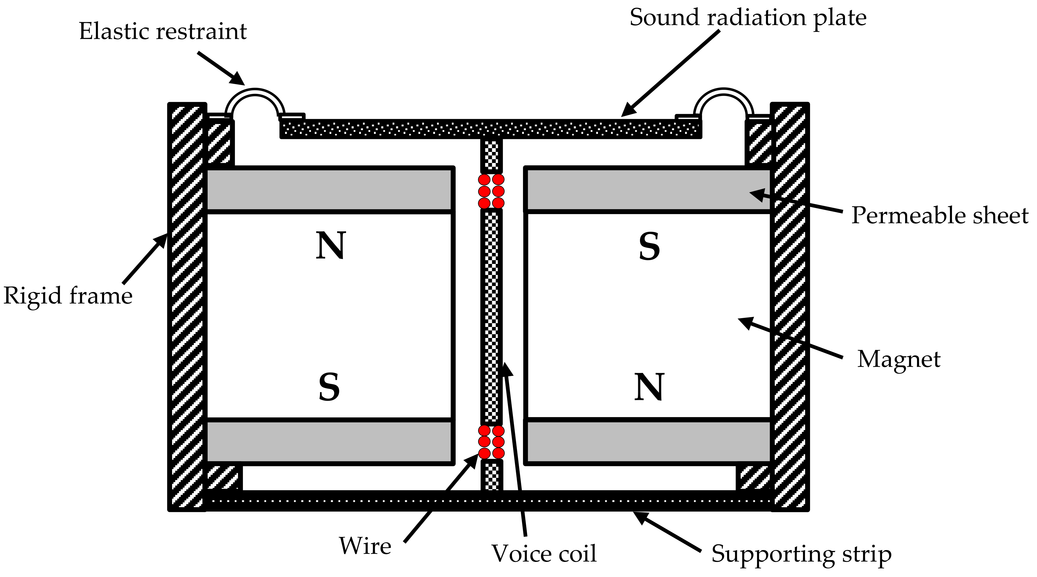
A schematic description of the strip type electro-magnetic exciter [
45] used in a panel-form sound radiator is shown in
Figure 1. Here, the voice coil attached to the sound radiation plate works as a stiffener to the plate. The electro-magnetic force
F generated by the strip-type exciter is assumed to be distributed uniformly on the plate as a line load. Here,
F is expressed as
F =
BLqI with
B = magnetic flux density,
Lq = length of wire immersed in the magnetic field,
I = electric current. It is noted that, in the audio industry, the system parameters of a speaker such as damping ratio, spring constant,
BLq, and mass can be determined via the measurement of the impedances of the speaker with and without an attached mass using LMS [
46]. Once these system parameters are available, they can be used to formulate the following vibro-acoustic method.
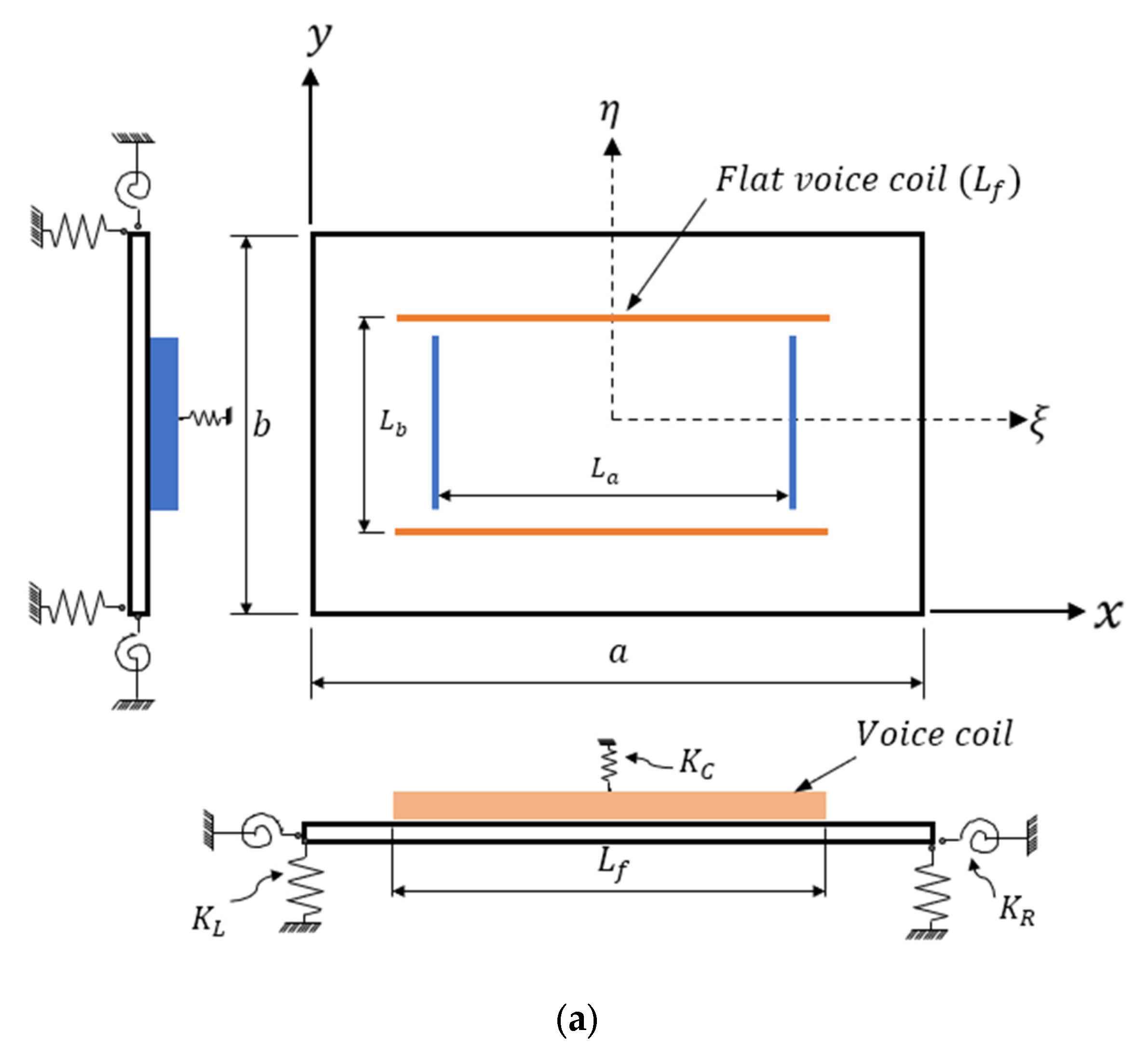
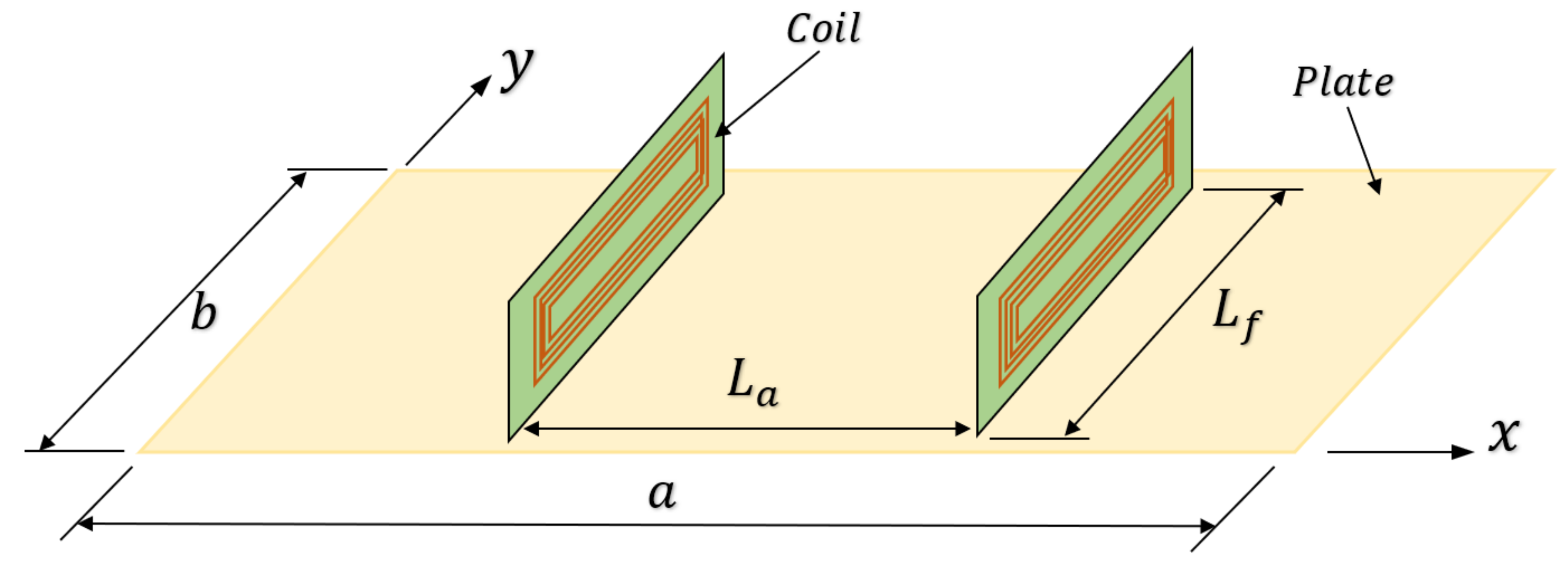
Consider the rectangular orthotropic sound radiation plate excited by two longitudinal and two transverse voice coils, which exert totally four line loads to the plate as shown in
Figure 2. Let
Lf be the length of the line load,
the distance between the longitudinal line loads, and
the distance between the transverse line loads. The plate of size
(length) ×
b (width) ×
(thickness) with
is elastically restrained along the plate periphery by distributed springs with translational and rotational spring constant intensities
and
, respectively. Each voice coil is restrained at the center by a spring with spring constant
. The
x-
y plane of the reference coordinate is located at the mid-plane of the plate. According to the SFSDT, the displacement field of the orthotropic plate is expressed as
where
,
, and
are the displacements at any point in the plate in the
x,
y, and
z directions, respectively;
,
are plate in-plane displacements;
is the bending induced deflection; and
is through-thickness shear induced deflection. It is noted that the in-plane displacements are taken into account in the above equation because the orthotropic plate becomes unsymmetrical when stiffeners are attached to the plate. It is also noted that in the SFSDT, only four displacement components, i.e.,
,
and
, are required to form the displacement field for the plate. In contrast, in the first-order shear deformation theory (FSDT), five displacement components, i.e., two in-plane displacements, vertical displacement and two shear rotations, are required to form the displacement field for the plate. Therefore, it is obvious that, in terms of computational efficiency, the present vibro-acoustic method formulated on the basis of the SFSDT should be more attractive than that on the basis of the FSDT or other high-order shear deformation theories.
The strain-displacement relations of the plate are expressed as
where
ε and
γ are normal and shear strains, respectively. The stress–strain relations of the orthotropic composite plate in the global
x-
y-
z coordinate system are expressed in the following general form [
47]:
where
σ and
τ are normal and shear stresses, respectively; and
are the lamina stiffness coefficients, which are expressed as
where
is Young’s modulus in the
th direction,
Poisson ratio, and
shear modulus. The plate stress resultants are defined as
In view of Equations (2), (3) and (5), the stress resultants can be expressed in terms of displacements
as
where
and
are the extensional and bending stiffness coefficients, respectively, which are written as
The strain energy,
, of the plate is
In view of the relations given in Equations (1)–(7), Equation (8) can be rewritten as
For vibration analysis, the knowledge of the actual distribution of the through thickness shear stress is not required. Hence, the shear correction factor has been adopted in calculating the above strain energy and is assumed to be 0.85.
The kinetic energy,
, of the plate is
where
is plate mass density. In view of Equation (1), Equation (10) can be rewritten as
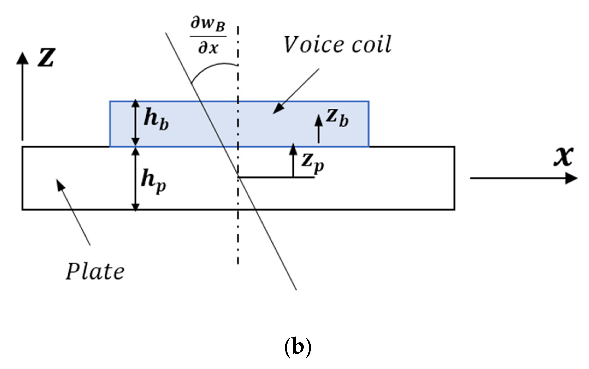
The voice coils are treated as simple beams in the vibration formulation. Observing the displacement continuity at the interface between the plate and beam, the displacement field of the beam oriented, for instance, in the
x-direction is expressed as
where
,
and
are beam displacements. The beam lateral displacement is negligible and thus treated as zero. The strains and strain energy of the beam are given, respectively, as
and
where
is beam Young’s modulus,
length,
height, and
thickness. The kinetic energy
Tb of the beam is
where
is beam mass density.
Consider one voice coil to be attached at the plate center. The strain energy, , stored in the elastic restraints is written as
The total strain energy
U and total kinetic energy
T of the sound radiating plate are written, respectively, as
and
where
N is number of beams.
Consider the non-dimensional coordinates
ξ and
η for which
ξ = 2
x/
a − 1 and
η = 2
y/
b − 1. Ritz method is used to study the free vibration of the sound radiation plate. The displacements of the plate expressed in terms of the non-dimensional coordinates
are
with
where
ω is circular frequency;
t is time;
are unknown constants;
,
,
,
,
,
,
,
denote the numbers of terms in the series. Legendre’s polynomials are used to represent the characteristic functions,
and
. The characteristic functions, for instance,
, are given as
with the satisfaction of the following orthogonality condition:
Define the functional Π =
Tmax −
Umax, where
Tmax and
Umax are the maximum kinetic and strain energies, respectively. The extremization of the functional Π gives the following eigenvalue problem.
where
K and
M are structural stiffness and mass matrices, respectively. The solution of the above eigenvalue problem can lead to the determination of the natural frequencies and mode shapes of the plate. The terms in
K and
M for an orthotropic plate with two longitudinal voice coils are listed in
Appendix A.
3. Determination of Sound Pressure Level Curve
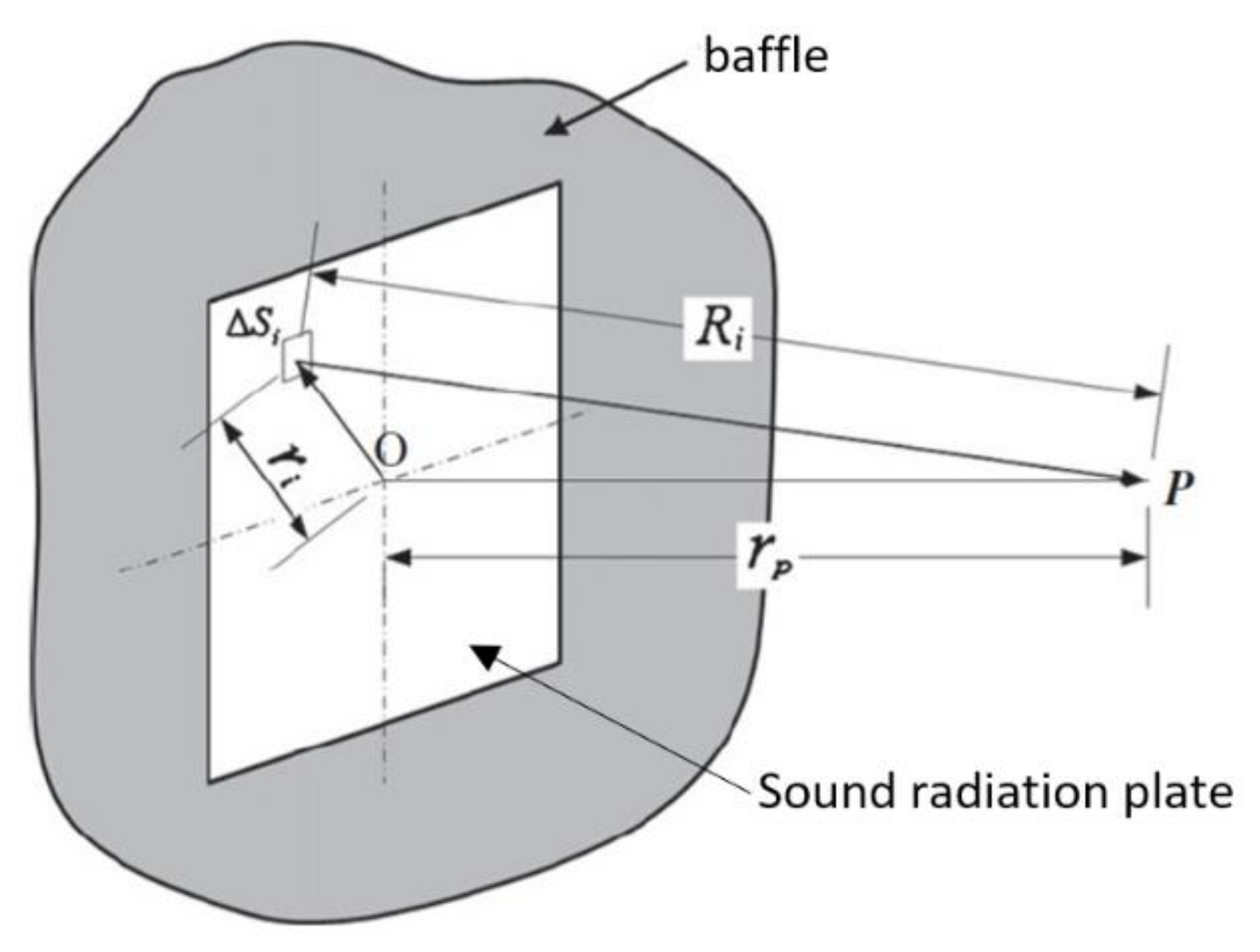
The smoothness of the sound pressure level curve can be used as a criterion for sound fidelity assessment of a sound radiator. Hence, the construction of the sound pressure level curve for a sound radiator is an essential task in the design process. When subjected to a harmonic excitation, a plate will deflect to move air for sound radiation. Consider the sound radiation of the baffled plate with area S in
Figure 3. The sound pressure
p(
r,
t) at point P in space can be calculated using the first Rayleigh integral.
If the effects of air loading on the plate vibration are neglected, the sound pressure
p(
r,
t) is expressed as
where
Ai is the central deflection amplitude of differential surface element
i;
is air density;
k is wave number (
) with
c being speed of sound;
is the distance between the plate center and the point of measurement;
the distance between the observation point and the position of the surface element at
;
θi is phase angle;
. For air at 20 °C and standard atmospheric pressure,
= 1.2 kg/m
3 and
c = 344 m/s. The SPL at point P can be calculated using the following equation.
with
where
T is period of harmonic load.
It is noted that both Equations (24) and (26) are determined via a numerical approach.
The deflection amplitude
Ai and phase angle
θi in Equation (24) can be obtained by solving the following equations of motion.
where the dot(s) above
C stands for derivative. The damping matrix
D is assumed to be in the form of Rayleigh damping.
with
α =
ζω,
β = 2
ζ/
ω where
ζ is damping ratio at the first resonant frequency of the elastically restrained plate. Once the
BL of the excitation force has been determined in the measurement of the sound radiator impedance and the input power of the strip-type electromagnetic exciter chosen, the force vector in Equation (27) can be established. It is noted that the derivation of the force vector
F has considered the contributions of
and
to the work done by the applied force. Consider a longitudinal line load of length
Lf having constant load amplitude
Fo, which is located at the plate center and oriented in the
ξdirection. The terms in
F are expressed as
For the case of two transverse line loads applied to the plate at the locations
and
, respectively, the terms in
F are expressed as
For the case of two longitudinal line loads applied to the plate at the locations
and
, respectively, the terms in
F are expressed as
It is worth to point out that according to the method of modal analysis, the vibration shape (response) of the plate is derived from the contributions of all the modes under consideration. When the excitation frequency coincides with a specific natural frequency, the amplitude of the mode shape associated with the natural frequency will dominate the amplitude of the vibration shape of the plate. On the other hand, from the energy point of view, each mode shape will share a portion of the total strain energy of the plate in vibration. Nevertheless, when the load is placed at the nodal line of a particular mode shape of the plate, the mode shape will be suppressed and thus have no contribution to the vibration shape (response) of the plate. In such case, the particular mode shape will have no share of the total strain energy of the plate, i.e., the total strain energy will be shared by the other modes so that the strain energy stored in each mode will increase. The contributions of the other modes (except the particular mode) for forming the vibration shape of the plate can be determined in the modal analysis through the solution of Equation (27). Mode shapes are also closely related to the sound radiation of the plate. Consider a particular mode shape that has adverse effects on sound radiation. When the excitation frequency coincides with the natural frequency of the particular mode, the amplitude of the mode will be magnified to cause resonance. Under this situation, the sound radiation power of the particular mode will play a dominant role in the sound radiation of the plate while the contributions of the other modes become negligible. The formation of this kind of vibration shape generally leads to the production of a SPL dip at that particular natural frequency. Nevertheless, when the load is placed at the nodal line of the particular mode shape, this mode shape will be suppressed so that no adverse effect on the sound radiation of the plate will be produced. On the other hand, the modes that are neighboring to the suppressed mode are generally beneficial to sound radiation. Therefore, from the energy point of view, the increases in the sound radiation powers of the other modes, especially those in the vicinity of the suppressed mode, will lead to the increase in sound radiation power of the vibration shape and make the SPL dip disappear. Hereafter, a procedure will be presented to illustrate the beneficial effects on smoothing SPL curves by eliminating the detrimental mode shape from the vibration shape.
5. Results and Discussion
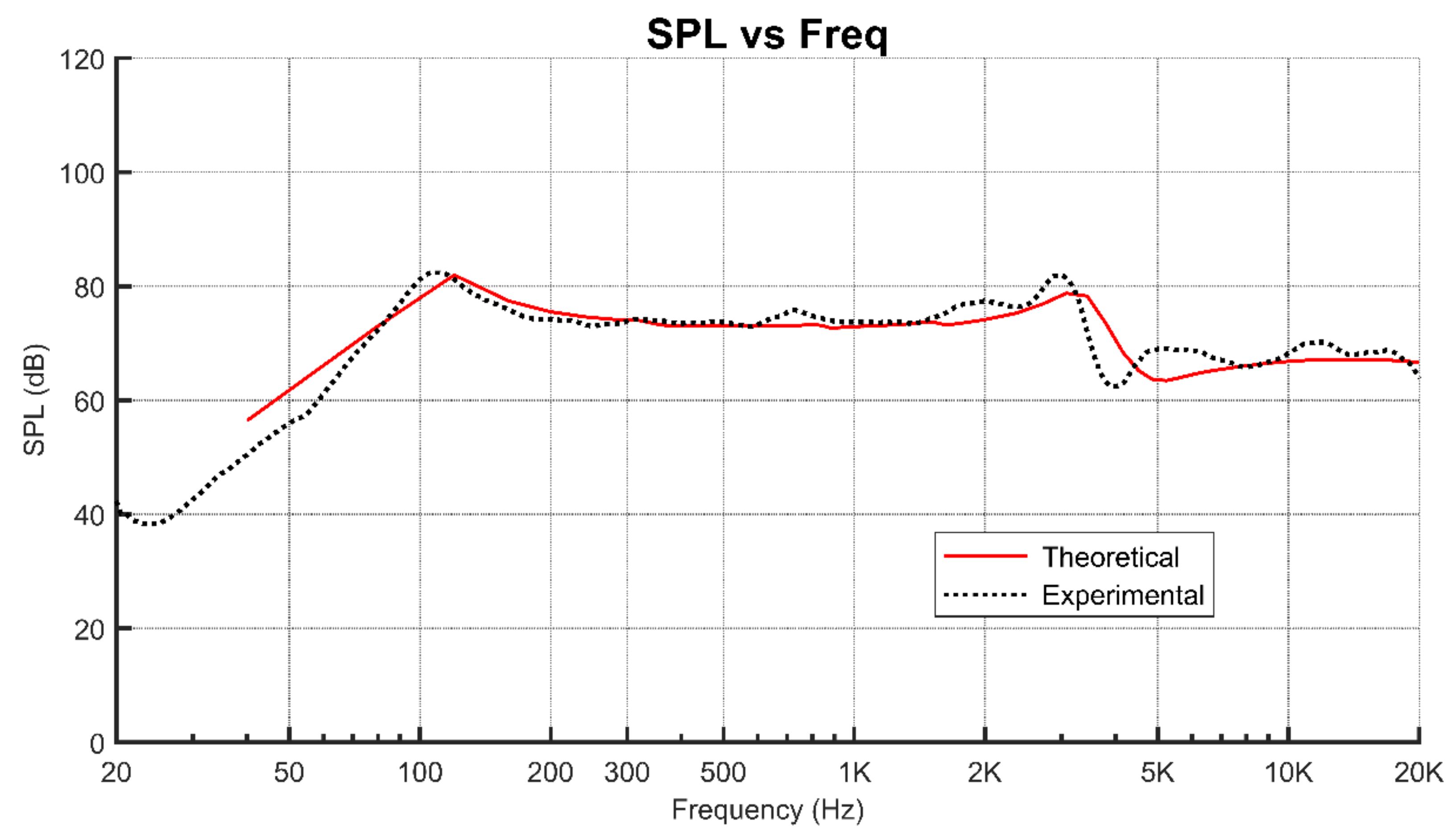
The experimental SPL curve of the panel-form sound radiator consisting of two transverse line loads will be used to validate the capability of the present method in predicting accurate SPL curves for orthotropic sound radiation plates. The theoretical SPL curve predicted using the present method is compared with the experimental one as shown in
Figure 5.
It is noted that both SPL curves have similar trends and are in good agreement in the audible frequency range 50–20 kHz. Furthermore, both the theoretical and experimental curves also comprise a major SPL dip in the frequency interval 2–4 kHz. Hence, the close agreement between the experimental and theoretical SPL curves has demonstrated the suitability of the present method for sound radiation analysis of panel-form composite sound radiators. In addition, it is noted that the capability of the proposed method in predicting accurate modal characteristics (natural frequency and mode shape) has been verified by the experimental results reported in the literature [
49]. On the other hand, it is worthwhile to point out that the vibration shape associated with the SPL dip is evolved from the mode shape associated with the natural frequency of 3083 Hz. In view of the evolution process involving the vibration shapes at different excitation frequencies as given in
Table 1, it is easy to notice that the vibration shape associated with the SPL dip is indeed evolved from the mode shape at 3083 Hz when the plate is excited by the two line loads. The inspection of the vibration shape associated with the major SPL dip has also revealed that the plate area is divided into two types of regions which have opposite phase angles. The interference among the sounds radiated from these regions leads to the major SPL dip at 4250 Hz.
The effects of excitation locations on the SPL curves of flat-panel speakers with different plate aspect ratios and fiber orientations will be studied using the proposed method. First, consider the case in which the plate is excited by a longitudinal voice coil (length = 53.73 mm) passing through the plate center. The dimensional parameters for the plate under consideration are chosen as aspect ratio a/b = 3, length a = 53.73 mm, and thickness = 2 mm. The plate material properties are the same as those adopted in the experimental study. The information of other system parameters adopted in the analysis is given as:
Voice coil: = 18.3 Gpa, = 0.145, 2600 kg/m3, = 2 mm (height), = 0.55 mm (thickness)
Amplitude of excitation force: = 0.576 N
Damping: ,
Elastic restraint: Surround, 2699 N/m; ; Voice coil, 600 N/m
The excitation force is uniformly distributed on the longitudinal stiffener. As mentioned before, some mode shapes may be closely related to SPL dips. Herein, several mode shapes, which may induce adverse effects on the sound radiation of the plate with different fiber angles, are listed in
Table 2. To make the table concise, the mode shapes that are beneficial to sound radiation are not shown in
Table 2. It is noted that the modal characteristics (natural frequency and mode shape) of the plate with 0° fiber angle are different from those of the plate with 90° fiber angle. Thus, it is foreseeable that the plate with different fiber angles may have different excitation patterns for suppressing the SPL dips of the plate. Again, the inspection of the mode shapes comprising regions with opposite phase angles has revealed that some of the mode shapes may lead to major SPL dips. Therefore, the suppression of the vibration shape evolved from a detrimental mode shape is an important task in the design of panel-form sound radiators.
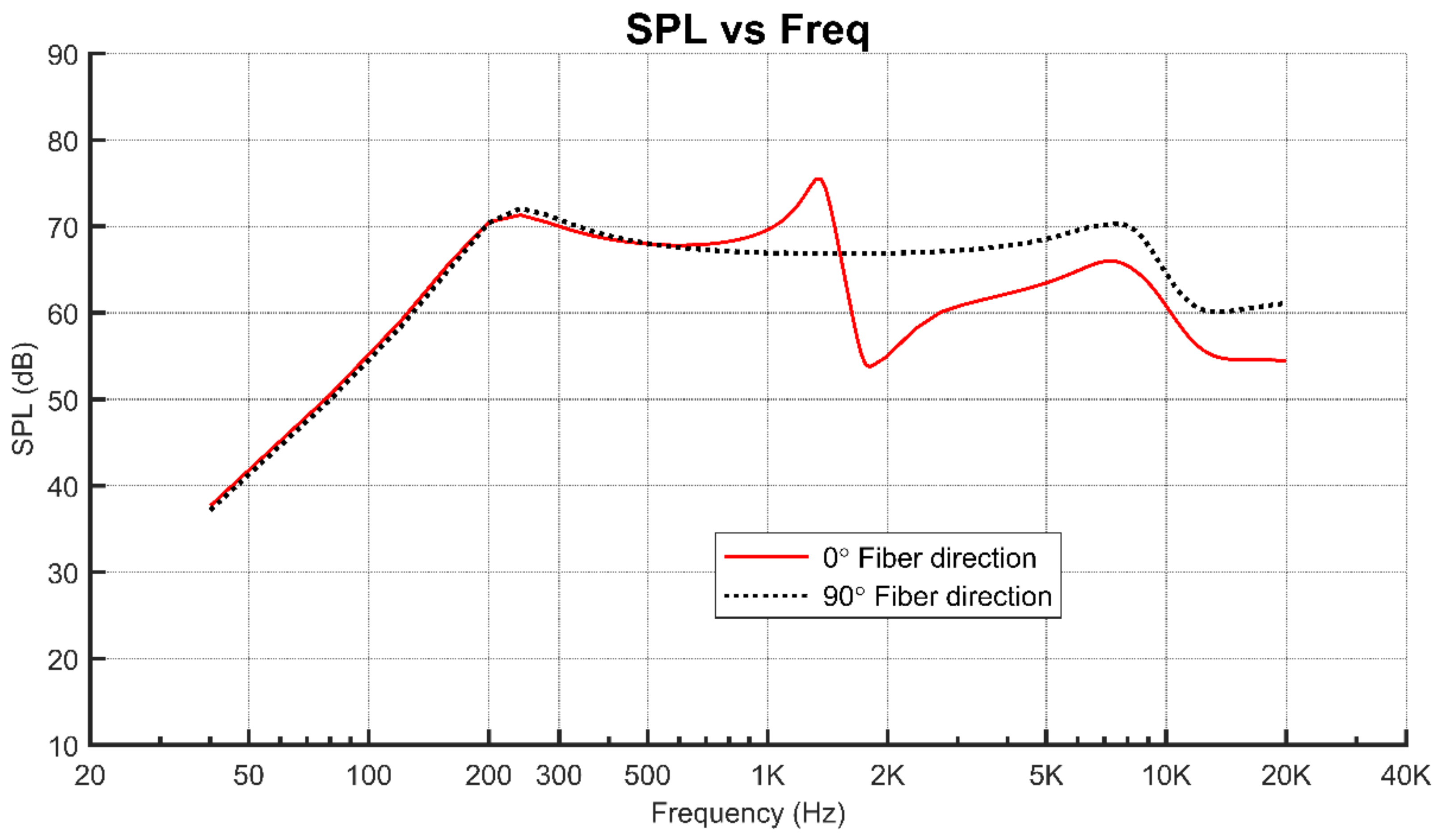
The SPL curves of the sound radiation plate with the fiber angle equal to 0° and 90° excited by a longitudinal line load are shown in
Figure 6.
It is noted that when the fiber angle is 0°, the vibration shape associated with the major SPL dip in the frequency interval 1.3–1.8 kHz is evolved from the transverse bending mode shape at 1373 Hz. The formation of the major SPL dip is due to the fact that one longitudinal line load passing through the plate center is unable to suppress but rather instigates the transverse bending mode shape at 1373 Hz. Furthermore, the vibration shape associated with the second major SPL dip in the interval 7.5–12 kHz is evolved from the mode shape at 7658 Hz. The side views of the mode shape at 1373 or 7658 Hz as shown in
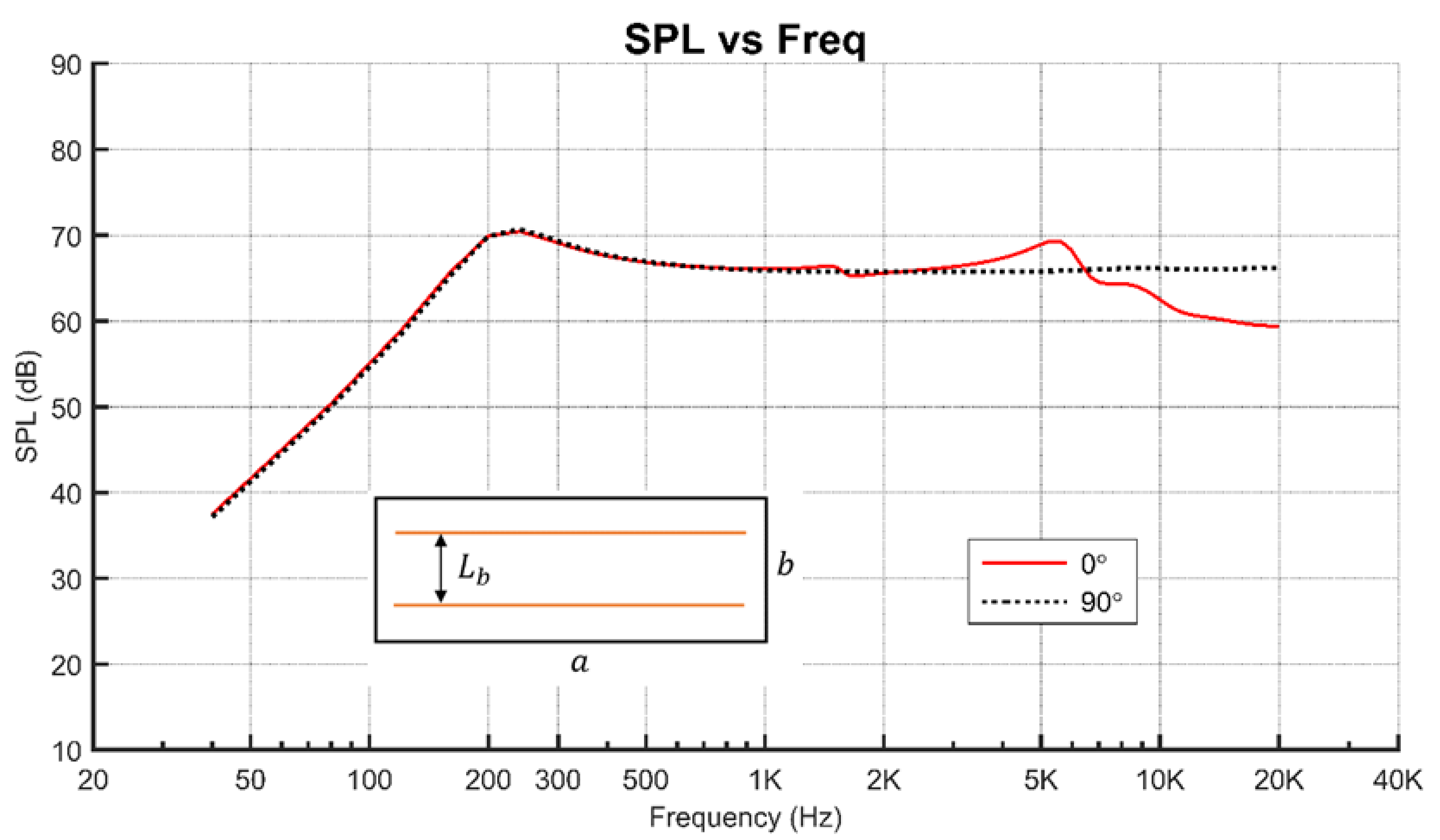
Table 2 have revealed the fact that the interference among the sounds radiated from the regions with opposite phase angles on the plate leads to the major SPL dip. On the other hand, for the 90° fiber angle case, the vibration shape associated with the SPL dip in the frequency interval 8–11 kHz is evolved from the mode shape at 8385 Hz. For this mode shape, the plate area has been divided into two groups of regions with opposite phase angles. The interference of the sounds radiated from these regions leads to the SPL drop in 8–11 kHz. To suppress the SPL dips, two line loads will be used to excite the plate. First, consider the exertion of two transverse line loads to the plate. The two line loads are symmetrically placed, respectively, on the left and right of the plate center with
La = 30 mm. It is noted that
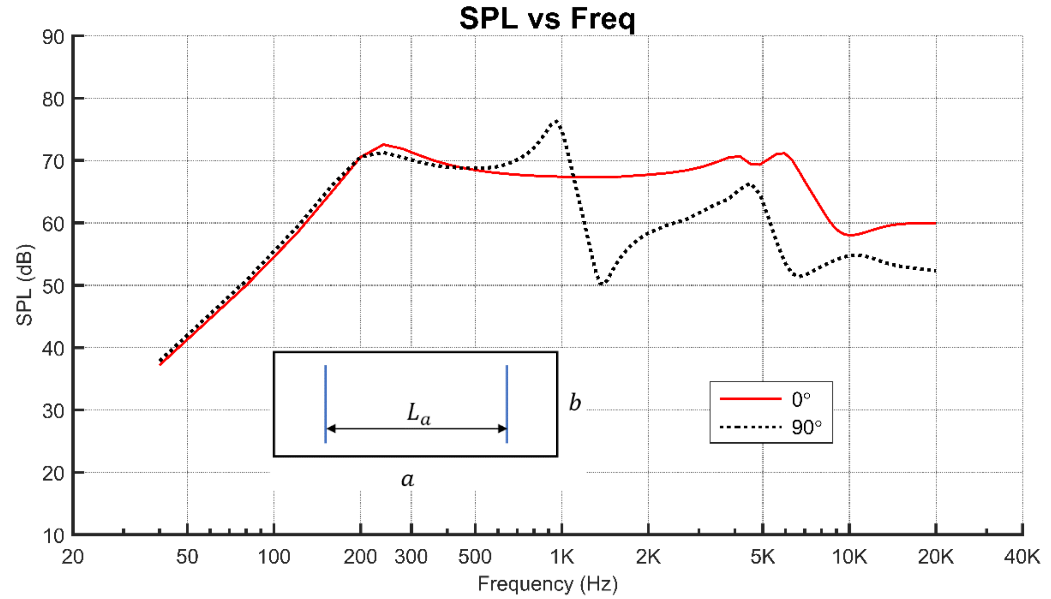
La coincides with the distance between the two nodal lines of the mode shape at 1897.7 Hz for the case of 0° fiber angle. The SPL curves for 0° and 90° fiber angles are shown in
Figure 7. It is noted that for the case of 0° fiber angle, the mode shapes at 1373 and 1897.7 Hz will not be instigated to produce major SPL dips. However, there is a major SPL drop around 7 kHz, which is caused by the mode shape at 7006 Hz. As for the case of 90° fiber angle, the mode shapes at 1058 and 4624 Hz will induce major SPL dips.
Now, consider the use of two longitudinal line loads with
= 9.8 mm. It is noted that
is chosen as the distance between the two nodal lines of the mode shape at 1373 Hz for the case of 0° fiber angle. The SPL curves for 0° and 90° fiber angles are shown in
Figure 8. It is noted that for the case of 0° fiber angle, the mode shape at 7006 Hz for the case of 0° fiber angle has been instigated to produce the major SPL drop. As for the case of 90° fiber angle, the SPL curve is relatively smooth and no major SPL dip has been induced. Therefore, in view of the above results, it is obvious that both the excitation pattern and fiber angle have significant effects on the smoothness of the SPL curve. For the orthotropic sound radiation plate with aspect ratio
a/
b = 3, the use of both two longitudinal line loads and 90° fiber angle can produce the smoothest SPL curve.
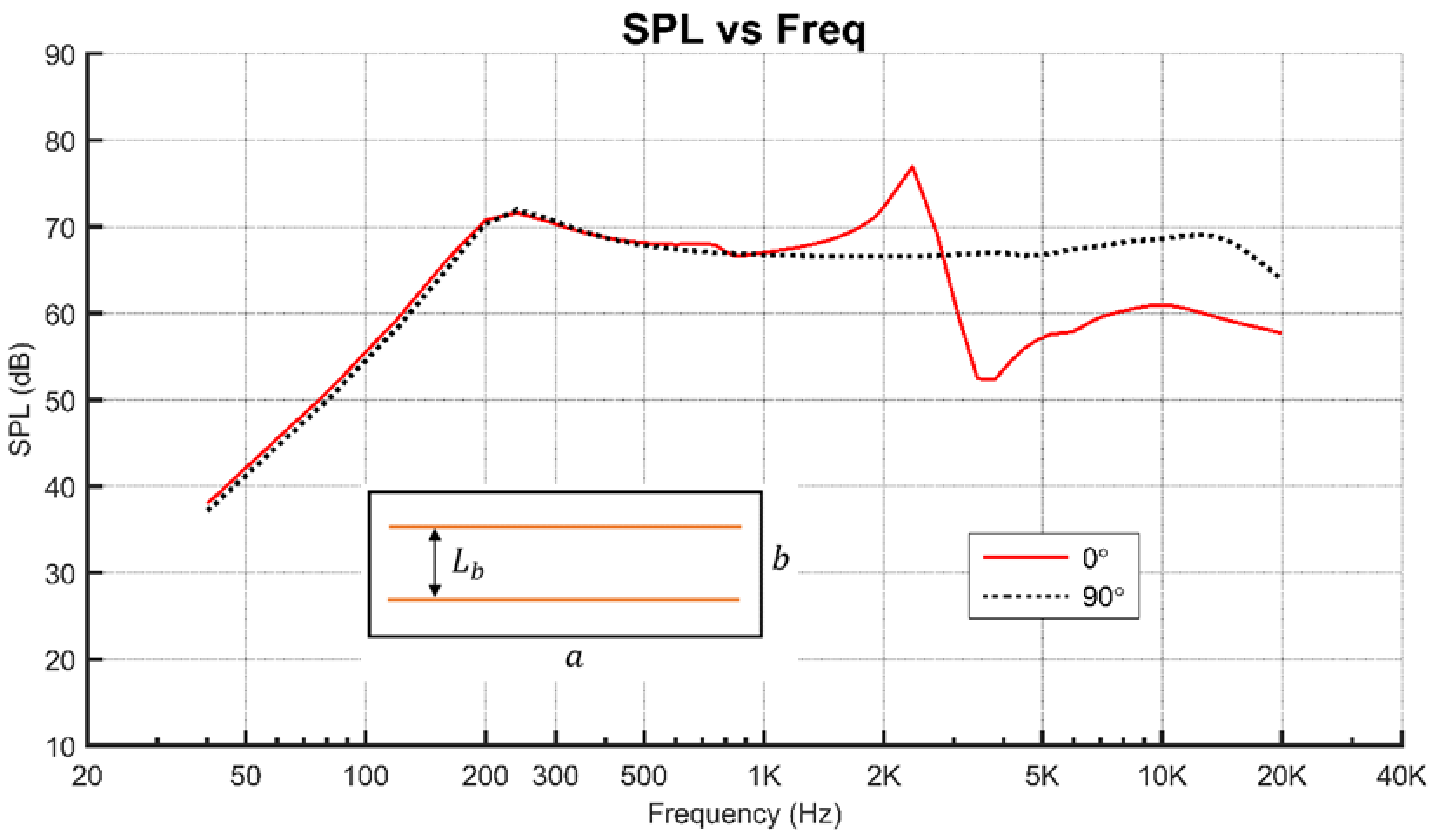
Next, consider the sound radiation of the composite plate with aspect ratio
a/
b = 2. The mode shapes, which may induce adverse effects on the sound radiation of the plate with different fiber angles, are listed in
Table 3.
The plate subjected to one or two line loads are to be studied. The SPL curves of the sound radiation plate with the fiber angle equal to 0° and 90° excited by a longitudinal line load are shown in
Figure 9.
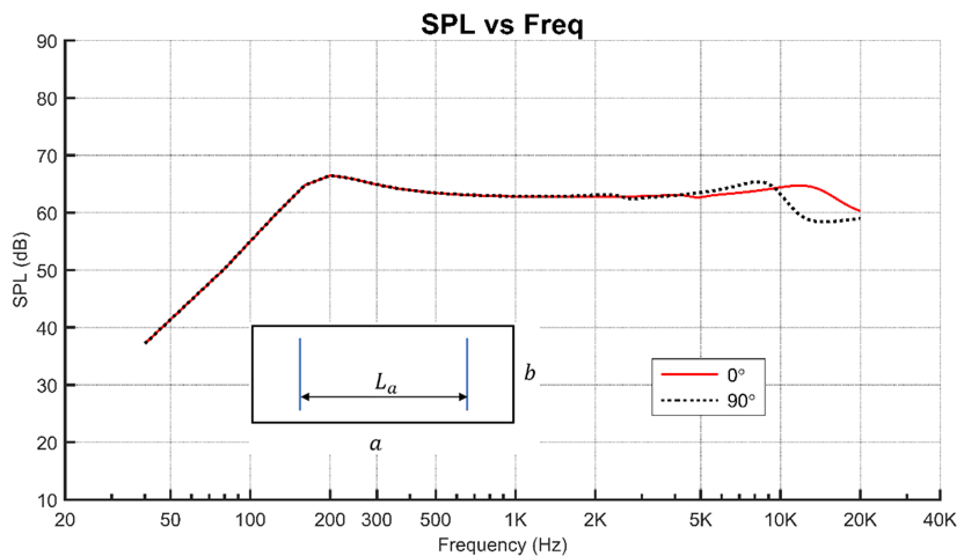
It is noted that for the case of 0° fiber angle, the vibration shapes associated with the major SPL dips in the frequency intervals 1–1.3 kHz and 5.4–8.5 kHz are evolved from the mode shapes at 1016.9 and 5436.2 Hz, respectively. On the other hand, for the 90° fiber angle case, the vibration shape associated with the SPL dip in the frequency interval 5.7–7.6 kHz is evolved from the mode shape at 5735 Hz. For these two cases, the location of the one line load, which is at the center of the plate, does not coincide with the nodal lines of the aforementioned detrimental mode shapes. Therefore, the detrimental mode shapes will be instigated to produce SPL dips to make the plate SPL curves unsmooth. To suppress the SPL dips, two line loads will be used to excite the plate. First, consider the exertion of two transverse line loads to the plate. The two line loads are symmetrically placed, respectively, on the left and right of the plate center with
= 28 mm. It is noted that
is chosen as the distance between the two nodal lines of the mode shape at 2532.4 Hz for the case of 0° fiber angle. The SPL curves for 0° and 90° fiber angles are shown in
Figure 10.
It is noted that for the case of 0° fiber angle, the mode shapes at 1373 and 1897.7 Hz will not be instigated to produce major SPL dips. However, there is a major SPL drop around 14 kHz which is caused by the mode shape at 14,796 Hz. As for the case of 90° fiber angle, the mode shape at 9782 Hz will induce the major SPL dip in the interval 9–12 kHz.
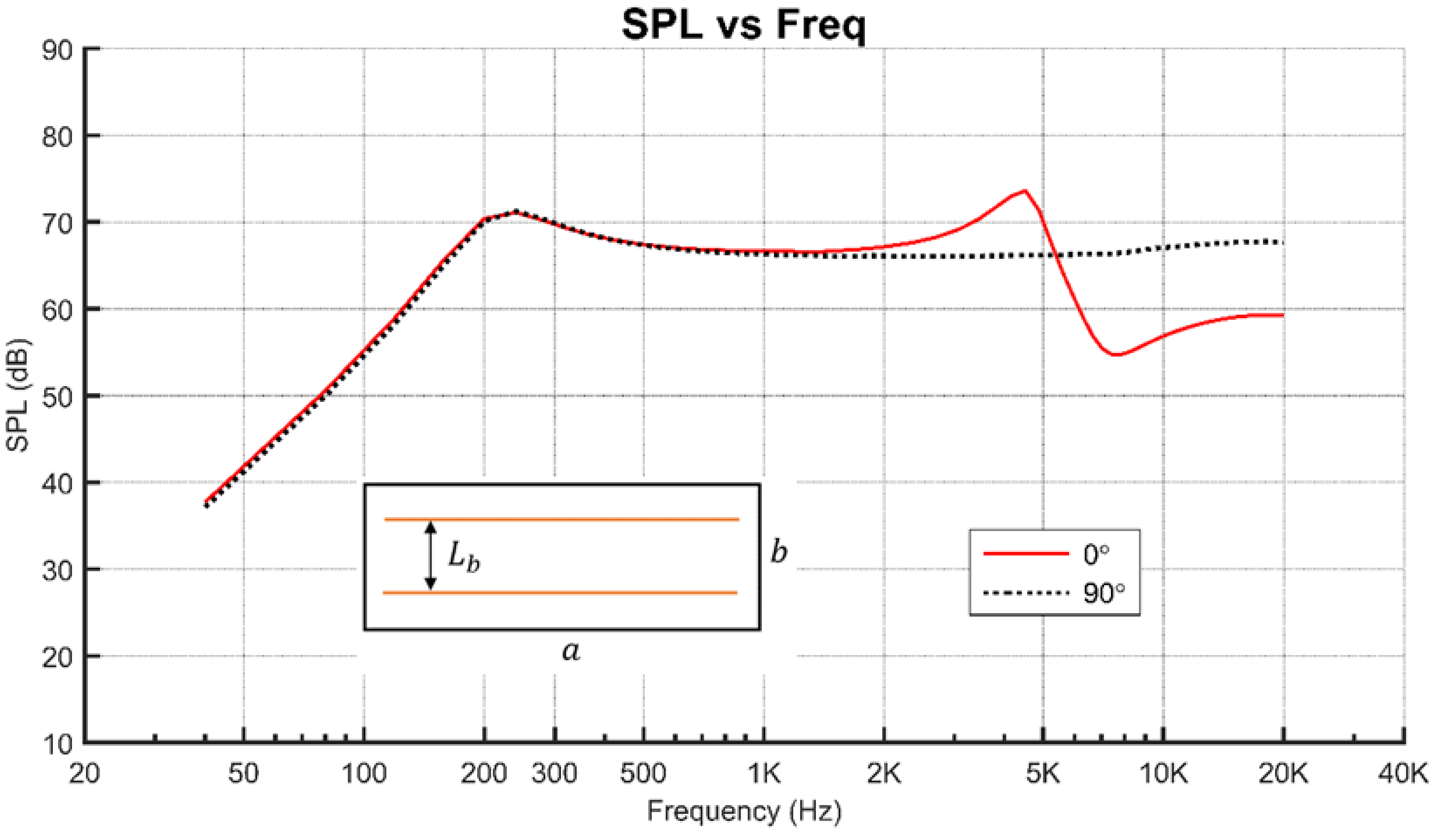
Now consider the use of two longitudinal line loads with
= 14 mm. It is noted that
is chosen as the distance between the two nodal lines of the mode shape at 1016.9 Hz for the case of 0° fiber angle. The SPL curves for 0° and 90° fiber angles are shown in
Figure 11.
It is noted that for the case of 0° fiber angle, the mode shape at 5436.2 Hz has been instigated to produce the major SPL dip in the interval 4.2 - 6.2kHz. As for the case of 90° fiber angle, the SPL curve is relatively smooth and no major SPL dip has been induced. Therefore, in view of the above results, it is obvious that for the orthotropic sound radiation plate with aspect ratio a/b = 2, the use of both two longitudinal line loads and 90° fiber angle can produce the smoothest SPL curve.
Finally, consider the sound radiation of the composite plate with aspect ratio
a/
b = 1. The mode shapes, which may induce adverse effects on the sound radiation of the plate with different fiber angles, are listed in
Table 4.
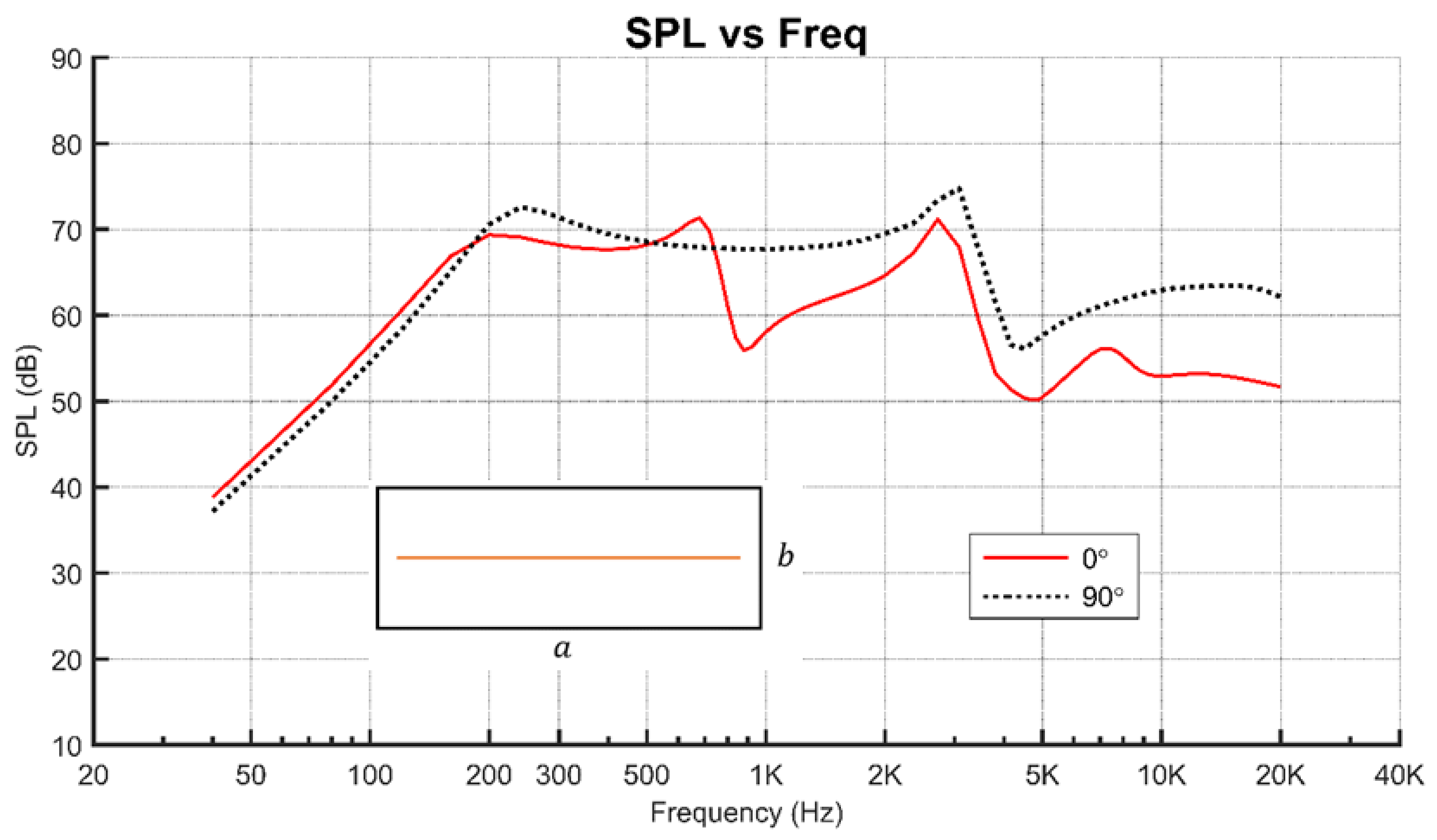
The plate subjected to one or two line loads are to be studied. The SPL curves of the sound radiation plate with the fiber angle equal to 0° and 90° excited by a longitudinal line load are shown in
Figure 12.
It is noted that for the case of 0° fiber angle, the vibration shapes associated with the major SPL dips in the frequency intervals 0.70–0.85 and 2.8–4.5 kHz are evolved from the mode shapes at 0.708 and 2.88 kHz. On the other hand, for the 90° fiber angle case, the vibration shape associated with the SPL dip in the frequency interval 3–4 kHz is evolved from the mode shape at 3.095 kHz. For these two cases, the nodal lines of the aforementioned mode shapes do not coincide with the centrally located longitudinal load. Therefore, the detrimental mode shapes will be instigated to produce the dips on the SPL curves. To suppress the SPL dips, two line loads will be used to excite the plate. Consider the exertion of two longitudinal line loads to the plate. The two line loads are symmetrically placed, respectively, above and below the plate center with
= 20 mm. It is noted that
is chosen as the distance between the two nodal lines of the mode shape at 3095 Hz for the case of 90° fiber angle. The SPL curves for 0° and 90° fiber angles are shown in
Figure 13.
It is noted that for the case of 0° fiber angle, the mode shape at 2.88 kHz for the case of 0° fiber angle has been instigated to produce the major SPL dip in the interval 2.5–3.4 kHz. As for the case of 90° fiber angle, the SPL curve is relatively smooth up to 14 kHz at which the mode shape at 14.339 kHz causes the SPL to drop slowly. Therefore, in view of the above results, it is obvious that for the orthotropic sound radiation plate with aspect ratio a/b = 1, the use of both two longitudinal line loads and 90° fiber angle can produce a relatively smooth SPL curve. It is noted that for a square orthotropic plate, the use of two transverse line loads together with 0° fiber angle will produce exactly the same results as those for the case of two longitudinal line loads together with 90° fiber angle.
In view of the results obtained in the above illustrative cases, it is noted that the use of one longitudinal line load is unable to smooth the SPL curves for the plates with aspect ratios equal to 3, 2, and 1. The existence of the dips/drops on the SPL curves is due to the fact that the line load is not located at the nodal lines of the detrimental mode shapes. Therefore, the general rule for SPL suppression is to place the line loads on the nodal lines of the detrimental mode shapes so that such mode shapes will be unable to generate adverse effects on sound radiation. It has been demonstrated that the placement of two line loads on the nodal lines of the detrimental mode shapes can produce relatively smooth SPL curves for the plates under consideration. The method and results presented in the paper should be of value in the design of panel-form speakers.


