
Design, Manufacturing, and Acoustical Analysis of a Helmholtz Resonator-Based Metamaterial Plate


Abstract
:1. Introduction
2. Model and Methods
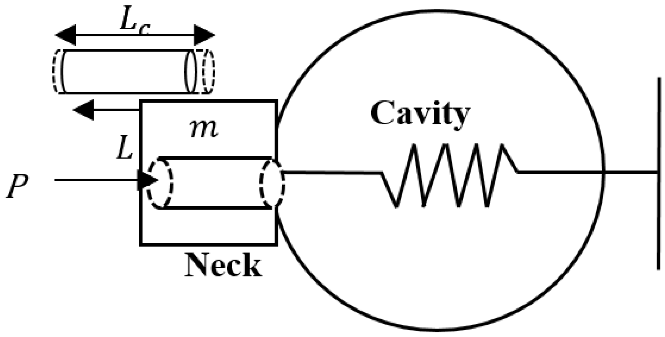
2.1. Helmholtz Resonator
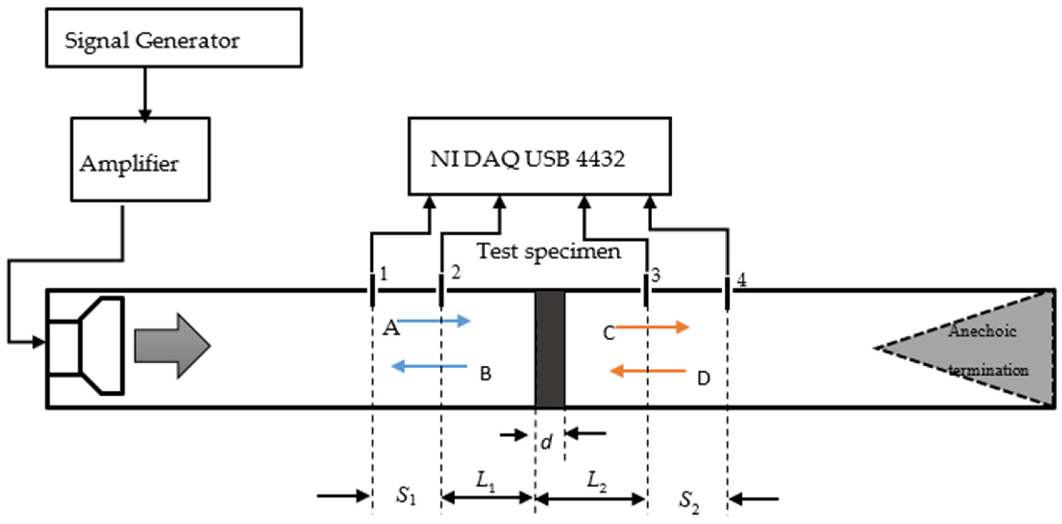
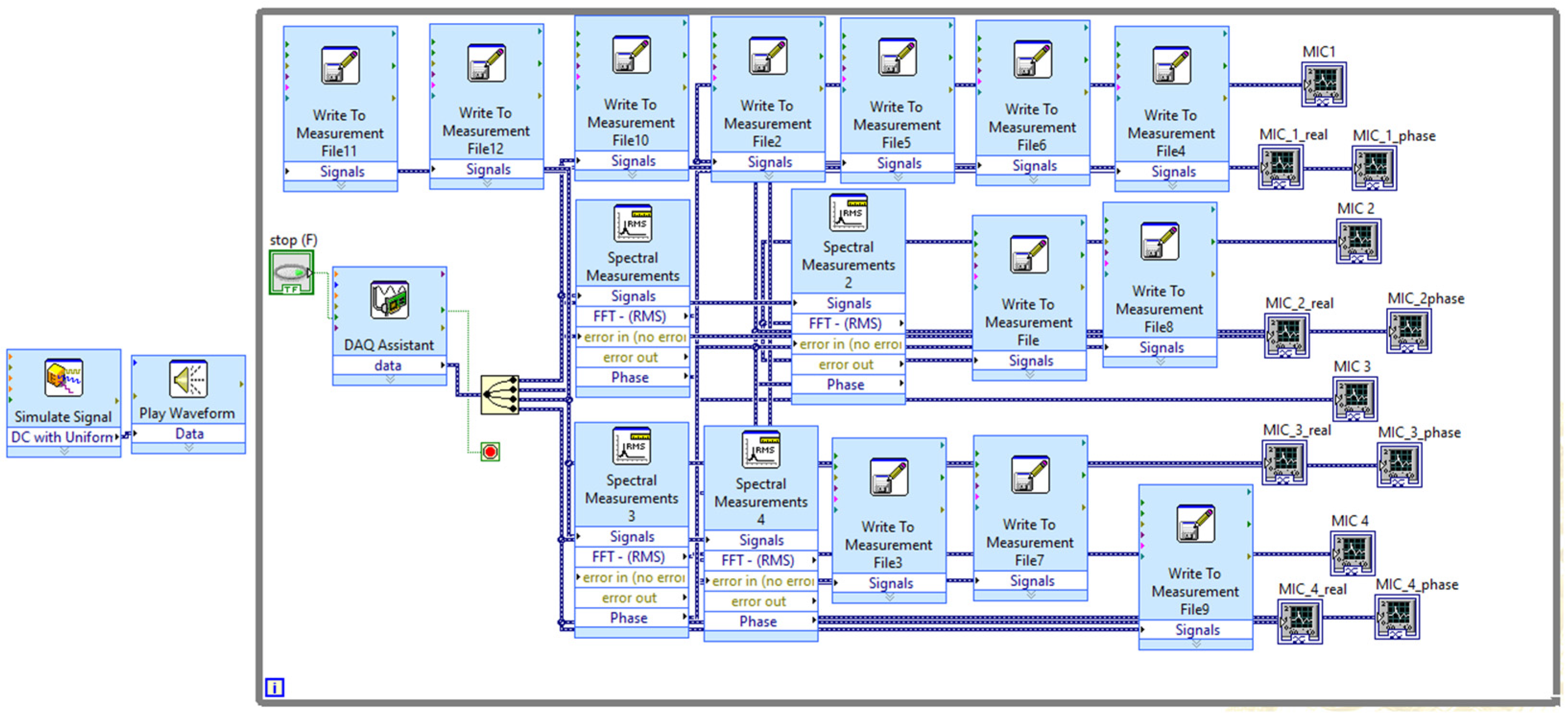
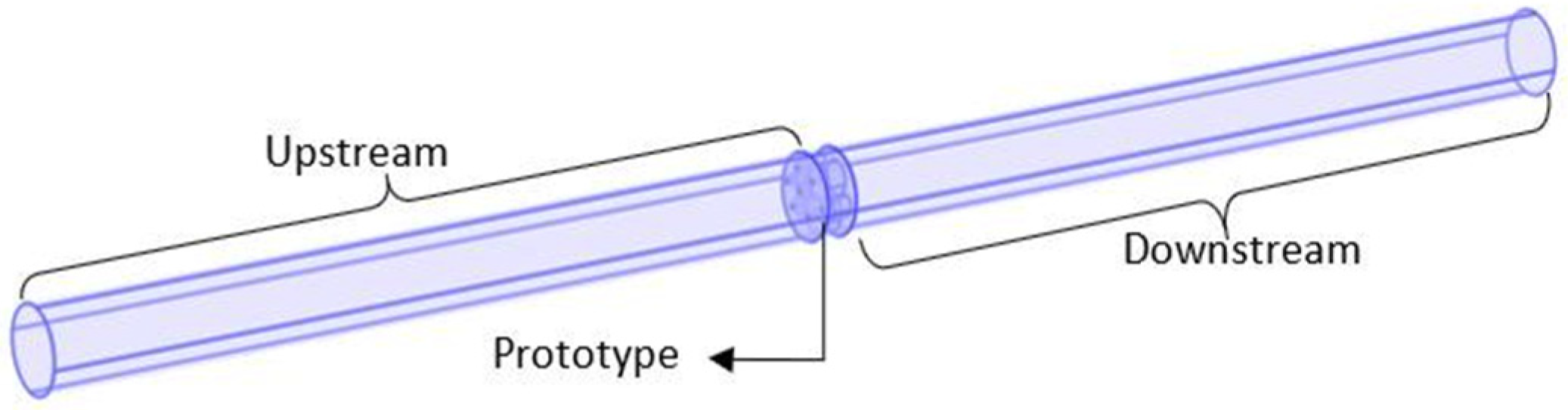
2.2. Four-Microphone Impedance Tube Method
2.3. Estimating Acoustic Properties
- Transmission Coefficient
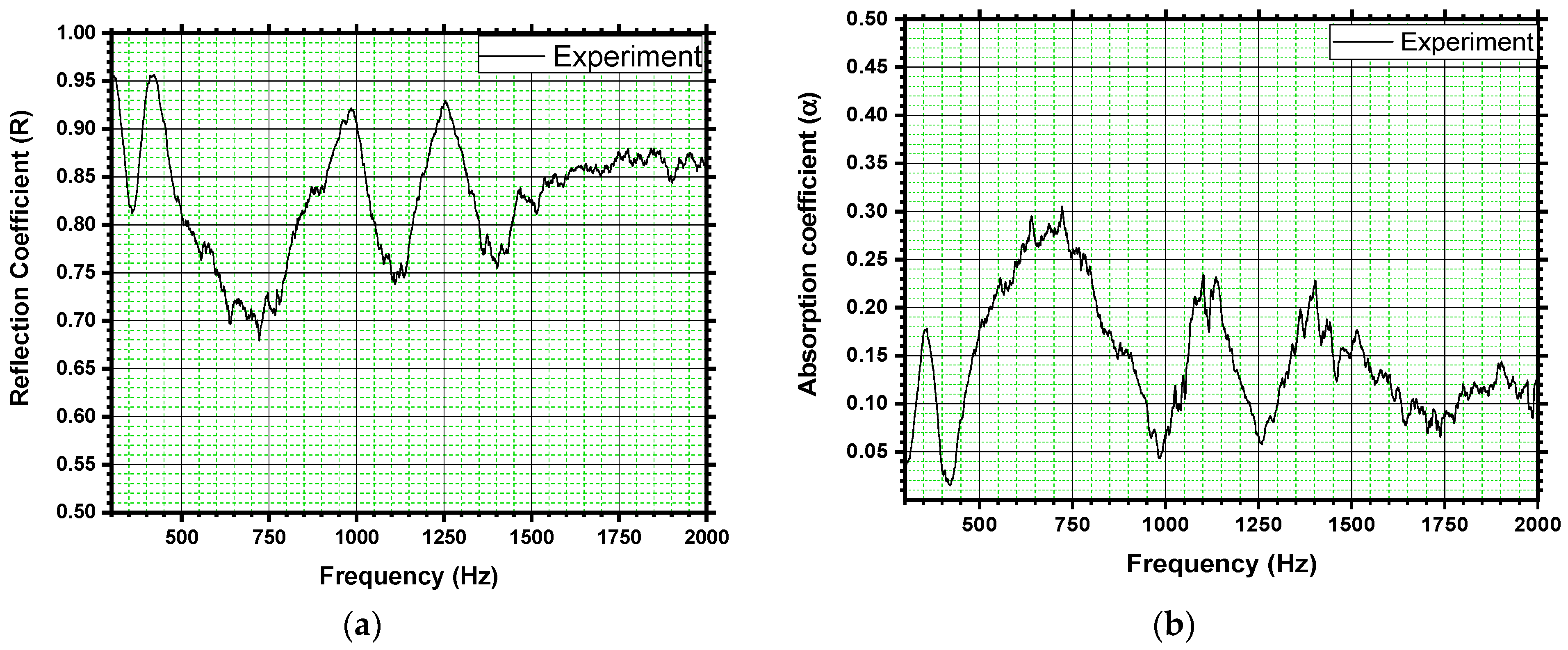
- Reflection Coefficient
- Absorption Coefficient
- Transmission Loss
3. Experimental and Numerical Study
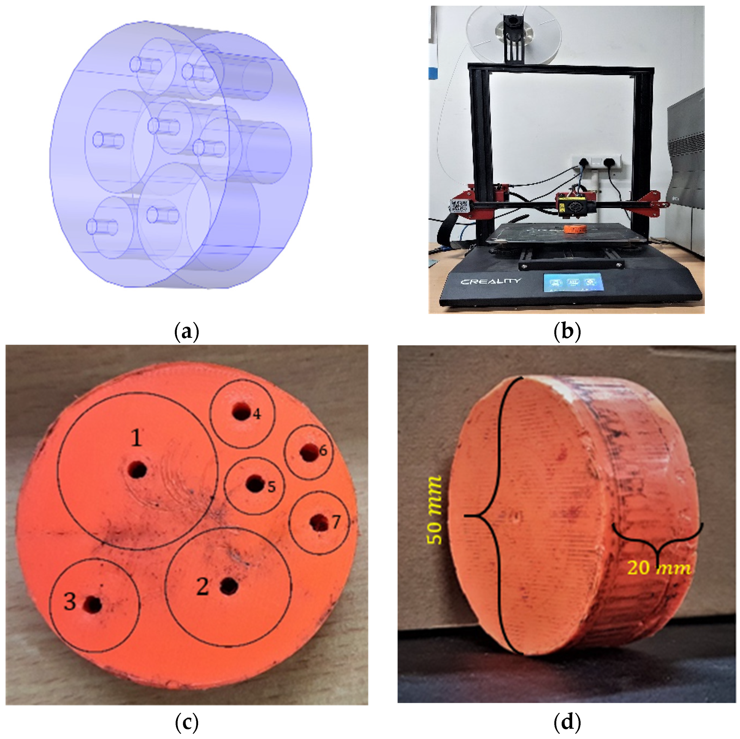
3.1. Fabrication of Metamaterial Plate Using Additive Manufacturing
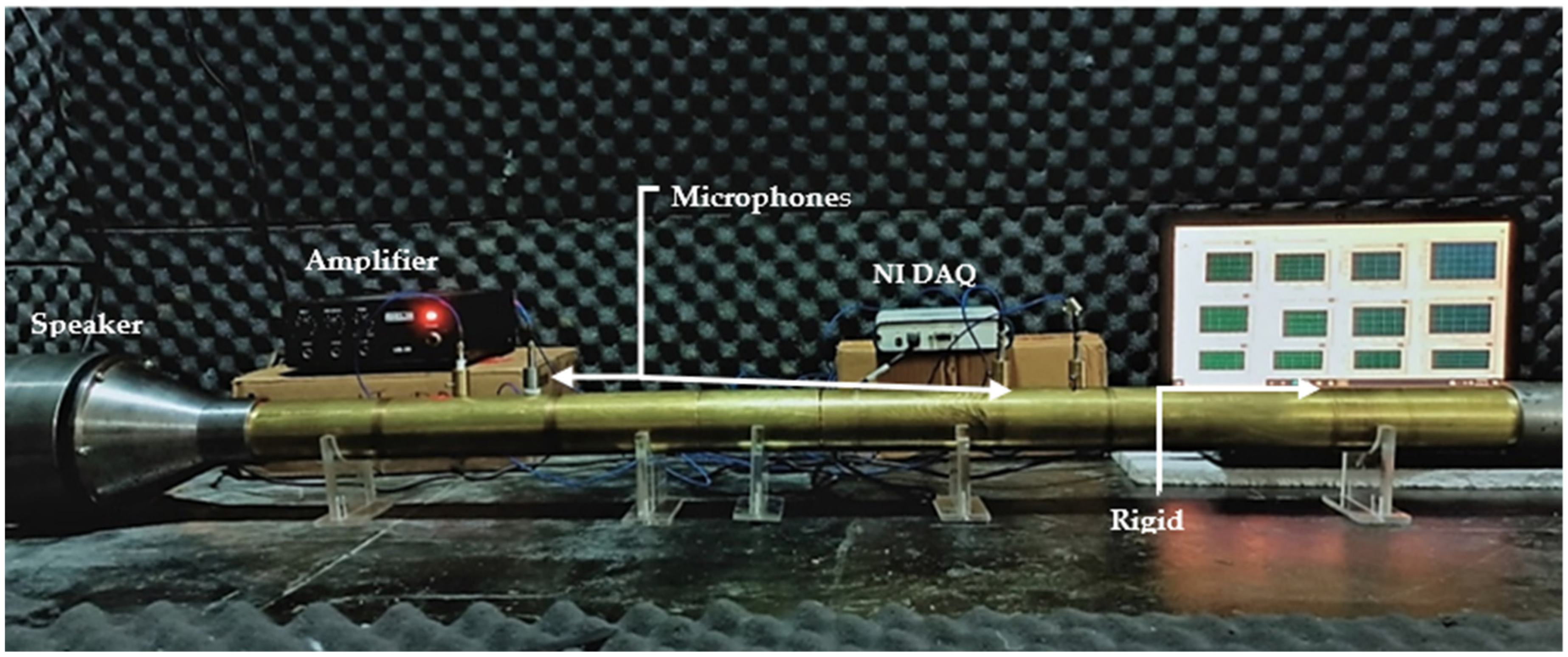
3.2. Experimental Testing of Metamaterial Plate Using a Four-Microphone Impedance Tube
3.3. Simulation to Estimate Acoustic Properties of Metamaterial Plate
4. Results and Discussion
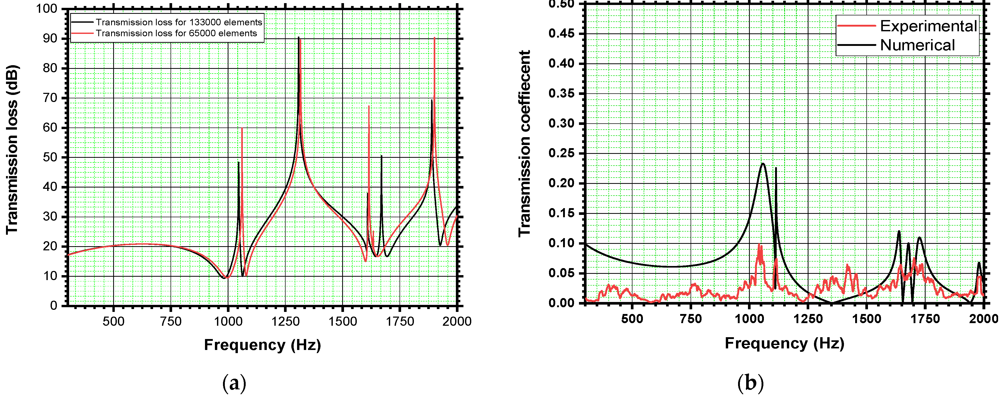
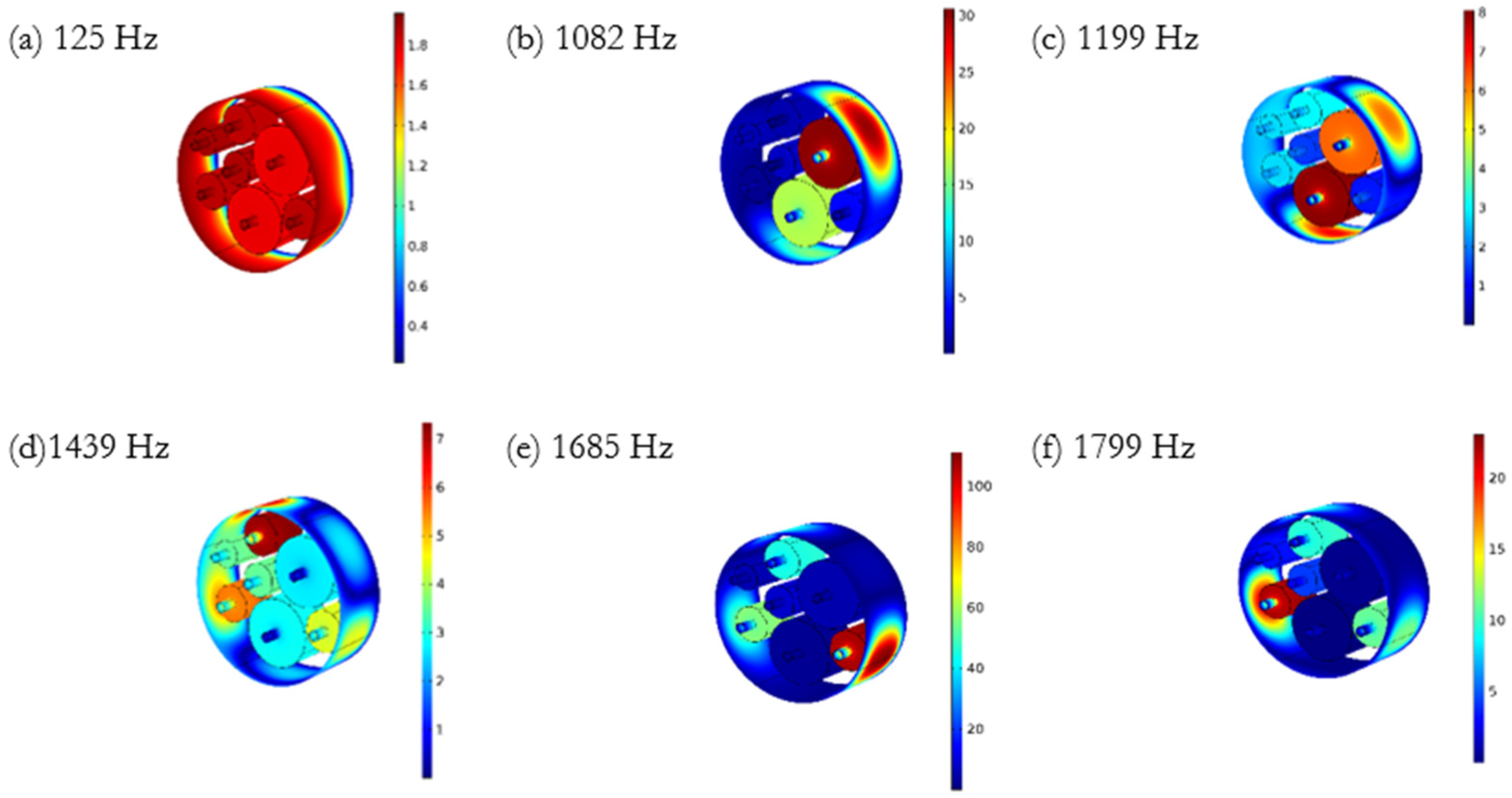
4.1. Transmission Loss
4.2. Reflection Coefficient and Absorption Coefficient
5. Conclusions
Author Contributions
Funding
Conflicts of Interest
References
- Cummer, S.A.; Christensen, J.; Alù, A. Controlling Sound with Acoustic Metamaterials. Nat. Rev. Mater. 2016, 1, 16001. [Google Scholar] [CrossRef] [Green Version]
- Zangeneh-Nejad, F.; Fleury, R. Active Times for Acoustic Metamaterials. Rev. Phys. 2019, 4, 100031. [Google Scholar] [CrossRef]
- Ma, G.; Sheng, P. Acoustic Metamaterials: From Local Resonances to Broad Horizons. Sci. Adv. 2016, 2, e1501595. [Google Scholar] [CrossRef] [Green Version]
- Liu, J.; Guo, H.; Wang, T. Review of Acoustic Metamaterials and Phononic Crystals. Crystals 2020, 10, 305. [Google Scholar] [CrossRef]
- Liu, Z.; Zhang, X.; Mao, Y.; Zhu, Y.Y.; Yang, Z.; Chan, C.T.; Sheng, P. Locally Resonant Sonic Materials. Science 2000, 289, 1734–1736. [Google Scholar] [CrossRef]
- Wu, Y.; Lai, Y.; Zhang, Z.Q. Elastic Metamaterials with Simultaneously Negative Effective Shear Modulus and Mass Density. Phys. Rev. Lett. 2011, 107, 105506. [Google Scholar] [CrossRef] [PubMed]
- Ciaburro, G.; Iannace, G. Modeling Acoustic Metamaterials Based on Reused Buttons Using Data Fitting with Neural Network. J. Acoust. Soc. Am. 2021, 150, 51–63. [Google Scholar] [CrossRef] [PubMed]
- Xie, Y.; Konneker, A.; Popa, B.I.; Cummer, S.A. Tapered Labyrinthine Acoustic Metamaterials for Broadband Impedance Matching. Appl. Phys. Lett. 2013, 103, 201906. [Google Scholar] [CrossRef] [Green Version]
- Yang, X.; Yin, J.; Yu, G.; Peng, L.; Wang, N. Acoustic Superlens Using Helmholtz-Resonator-Based Metamaterials. Appl. Phys. Lett. 2015, 107, 193505. [Google Scholar] [CrossRef]
- Laureti, S.; Hutchins, D.A.; Davis, L.A.J.; Leigh, S.J.; Ricci, M. High-Resolution Acoustic Imaging at Low Frequencies Using 3D-Printed Metamaterials. AIP Adv. 2016, 6, 121701. [Google Scholar] [CrossRef] [Green Version]
- Yang, Z.; Dai, H.M.; Chan, N.H.; Ma, G.C.; Sheng, P. Acoustic Metamaterial Panels for Sound Attenuation in the 50–1000 Hz Regime. Appl. Phys. Lett. 2010, 96, 041906. [Google Scholar] [CrossRef]
- Huang, S.; Fang, X.; Wang, X.; Assouar, B.; Cheng, Q.; Li, Y. Acoustic Perfect Absorbers via Helmholtz Resonators with Embedded Apertures. J. Acoust. Soc. Am. 2019, 145, 254–262. [Google Scholar] [CrossRef] [PubMed]
- Guo, J.; Fang, Y.; Jiang, Z.; Zhang, X. An Investigation on Noise Attenuation by Acoustic Liner Constructed by Helmholtz Resonators with Extended Necks. J. Acoust. Soc. Am. 2021, 149, 70–81. [Google Scholar] [CrossRef] [PubMed]
- London, A. Transmission of Reverberant Sound through Single Walls. J. Res. Natl. Bur. Stand. (1934) 1949, 42, 605. [Google Scholar] [CrossRef]
- Nilsson, A.C. Wave Propagation in and Sound Transmission through Sandwich Plates. J. Sound Vib. 1990, 138, 73–94. [Google Scholar] [CrossRef]
- Narayanan, S. Sound Transmission Through Panel Damped. J. Sound Vib. 1982, 80, 315–327. [Google Scholar] [CrossRef]
- Groby, J.-P.; Lagarrigue, C.; Brouard, B.; Dazel, O.; Tournat, V.; Nennig, B. Enhancing the Absorption Properties of Acoustic Porous Plates by Periodically Embedding Helmholtz Resonators. J. Acoust. Soc. Am. 2015, 137, 273–280. [Google Scholar] [CrossRef] [Green Version]
- Sharma, G.S.; Skvortsov, A.; MacGillivray, I.; Kessissoglou, N. On Superscattering of Sound Waves by a Lattice of Disk-Shaped Cavities in a Soft Material. Appl. Phys. Lett. 2020, 116, 041602. [Google Scholar] [CrossRef]
- Sharma, G.S.; Skvortsov, A.; MacGillivray, I.; Kessissoglou, N. Sound Scattering by a Bubble Metasurface. Phys. Rev. B 2020, 102, 214308. [Google Scholar] [CrossRef]
- Prydz, R.A.; Wirt, L.S.; Kuntz, H.L.; Pope, L.D. Transmission Loss of a Multilayer Panel with Internal Tuned Helmholtz Resonators. J. Acoust. Soc. Am. 1990, 87, 1597–1602. [Google Scholar] [CrossRef]
- Wu, D.; Zhang, N.; Mak, C.M.; Cai, C. Hybrid Noise Control Using Multiple Helmholtz Resonator Arrays. Appl. Acoust. 2019, 143, 31–37. [Google Scholar] [CrossRef]
- Herrero-Durá, I.; Cebrecos, A.; Picó, R.; Romero-García, V.; García-Raffi, L.M.; Sánchez-Morcillo, V.J. Sound Absorption and Diffusion by 2D Arrays of Helmholtz Resonators. Appl. Sci. 2020, 10, 1690. [Google Scholar] [CrossRef] [Green Version]
- Jena, D.P.; Dandsena, J.; Jayakumari, V.G. Demonstration of Effective Acoustic Properties of Different Configurations of Helmholtz Resonators. Appl. Acoust. 2019, 155, 371–382. [Google Scholar] [CrossRef]
- CAI, C.; MAK, C.M. Noise Attenuation Capacity of a Helmholtz Resonator. Adv. Eng. Softw. 2018, 116, 60–66. [Google Scholar] [CrossRef]
- Selamet, A.; Dickey, N.S.; Radavich, P.M.; Novak, J.M. Theoretical, Computational and Experimental Investigation of Helmholtz Resonators: One-Dimensional versus Multi-Dimensional Approach. SAE Trans. 1994, 103, 970–979. [Google Scholar]
- Sugimoto, N.; Horioka, T. Dispersion Characteristics of Sound Waves in a Tunnel with an Array of Helmholtz Resonators. J. Acoust. Soc. Am. 1995, 97, 1446–1459. [Google Scholar] [CrossRef]
- Fang, N.; Xi, D.; Xu, J.; Ambati, M.; Srituravanich, W.; Sun, C.; Zhang, X. Ultrasonic Metamaterials with Negative Modulus. Nat. Mater. 2006, 5, 452–456. [Google Scholar] [CrossRef] [PubMed]
- Lee, T.; Nomura, T.; Iizuka, H. Damped Resonance for Broadband Acoustic Absorption in One-Port and Two-Port Systems. Sci. Rep. 2019, 9, 13077. [Google Scholar] [CrossRef]
- Fahy, F. Foundations of Engineering Acoustics; Elsevier: San Diego, CA, USA; London, UK, 2001. [Google Scholar]
- Kinsler, L.E.; Frey, A.R.; Coppens, A.B.; Sanders, J.V. Fundamentals of Acoustics; John Wiley & Sons: New York, NY, USA, 2009. [Google Scholar]
- Allard, J.F. Methods of Measuring the Acoustic Impedance. In Propagation of Sound in Porous Media; Springer: Dordrecht, The Netherlands, 1993; pp. 207–219. [Google Scholar]
- ASTM. Standard Test Method for Normal Incidence Determination of Porous Material Acoustical Properties Based on the Transfer Matrix Method E2611-19; ASTM International: West Conshohocken, PA, USA, 2019. [Google Scholar]


| Diameter (mm) | 22 | 20 | 12 | 11.6 | 11 | 10 | 8 |
| Resonance (Hz) | 682 | 751 | 1219 | 1295 | 1365 | 1502 | 1877 |
Publisher’s Note: MDPI stays neutral with regard to jurisdictional claims in published maps and institutional affiliations. |
© 2021 by the authors. Licensee MDPI, Basel, Switzerland. This article is an open access article distributed under the terms and conditions of the Creative Commons Attribution (CC BY) license (https://creativecommons.org/licenses/by/4.0/).
Share and Cite
Dogra, S.; Gupta, A. Design, Manufacturing, and Acoustical Analysis of a Helmholtz Resonator-Based Metamaterial Plate. Acoustics 2021, 3, 630-641. https://doi.org/10.3390/acoustics3040040
Dogra S, Gupta A. Design, Manufacturing, and Acoustical Analysis of a Helmholtz Resonator-Based Metamaterial Plate. Acoustics. 2021; 3(4):630-641. https://doi.org/10.3390/acoustics3040040
Chicago/Turabian StyleDogra, Sourabh, and Arpan Gupta. 2021. "Design, Manufacturing, and Acoustical Analysis of a Helmholtz Resonator-Based Metamaterial Plate" Acoustics 3, no. 4: 630-641. https://doi.org/10.3390/acoustics3040040