Article

Corrosion Behavior of Stainless Steels in CO2 Absorption Process Using Aqueous Solution of Monoethanolamine (MEA)

by
Fani Stergioudi
1,*,
Aikaterini Baxevani
1,
Christina Florou
1,
Nikolaos Michailidis
1,
Evie Nessi
2,
Athanasios I. Papadopoulos
2 and
Panagiotis Seferlis
2,3
1
Physical Metallurgy Laboratory, Mechanical Engineering Department, Aristotle University of Thessaloniki, 54124 Thessaloniki, Greece
2
Chemical Process and Energy Resources Institute, Centre for Research and Technology Hellas, 57001 Thermi, Greece
3
Laboratory of Machine Dynamics, Mechanical Engineering Department, Aristotle University of Thessaloniki, 54124 Thessaloniki, Greece
*
Author to whom correspondence should be addressed.
Corros. Mater. Degrad. 2022, 3(3), 422-438; https://doi.org/10.3390/cmd3030025
Submission received: 18 May 2022 / Revised: 6 July 2022 / Accepted: 26 July 2022 / Published: 4 August 2022
(This article belongs to the Special Issue Corrosion Barrier Coatings)

Abstract

:
The corrosion behavior of two stainless steels (316L and 304L) was evaluated using a CO2-loaded aqueous solution of 30 wt.% monoethanolamine (MEA) with a view to simulating corrosion related mechanisms in amine treatment procedures. Corrosion behavior was experimentally evaluated as a function of CO2 loading and solution temperature, using electrochemical techniques (polarization curves, cyclic polarization, and EIS measurement). The results reveal that the aqueous MEA solution containing CO2 creates a favorable environment for the corrosion of both stainless steels. The rate of corrosion is accelerated when the temperature of the loaded MEA solution rises, which was attributed to the thermal degradation of the loaded MEA, thus causing higher kinetics of the cathodic reactions at higher temperatures. More specifically, for the SS 304L the corrosion rate is almost doubled when the solution temperature is increased from 25 °C to 40 °C and is quadrupled when the solution temperature rises to 80 °C. For the SS 316L, the corrosion rate becomes almost threefold and sixfold upon increasing temperature of the load amine solution to 40 °C and 80 °C, respectively. The overall corrosion rate of SS 316L is lower with respect to the SS 304L for the same temperature and loading conditions. The essential dependency of corrosion rate on solution type (unloaded and loaded MEA solution) demonstrates that the corrosion process and reactions are controlled by a diffusion mechanism.

1. Introduction

Among several methods for capturing CO2 from industrial exhaust gas, the most attractive, in terms of flexibility, is the gas absorption technique employing aqueous solutions of alkanolamines, also known as the amine treatment procedure. However, all amine treatment plants have encountered corrosion issues [1].
Corrosion has long been regarded as one of the most serious operating issues in alkanolamine power plants, with studies showing that the rate of corrosion is greatly influenced by the temperature and purity of the flue gas, as well as the materials used to construct the installation [1,2,3,4]. Since much of the equipment and piping is made of carbon steel for cost considerations, these components are susceptible to corrosion from a variety of factors, such as dissolved acid gases, oxygen, and amine degradation products [2,5,6,7,8,9].
Corrosion in amine treatment plants can provoke undesirable sudden shutdown of the plant resulting in production loss or industrial accidents, leading to a significant reduction of the equipment service life. Understanding the key factors that induce corrosion in certain parts of the amine plant is critical for securing a smooth operation and a prolonged service life. In this context, the identification of the acting corrosion mechanisms and the prevailing types of corrosion are pivotal in mitigating corrosion [4,10,11,12,13].
Most corrosion failures in amine treating plants are ascribed to high temperatures and dissolved acid gas, since amines themselves are generally not considered corrosive due to their high alkalinity [11,12]. As for the corrosive agents, the most important feature is the chemical activity of the dissolved acid gas that is responsible for the corrosion. Activity varies with amine type, amine concentration, acid gas loads, concentrations, chemical identity of impurities (usually of heat-stable salts) and temperature. This may give the impression that some amine systems appear more corrosive than others [12].
The mechanisms of reaction of amines with CO2 and acid gases are critical as the amine solvents themselves are generally relatively inert to corrosion. However, there is insufficient understanding of the mechanisms by which corrosion itself occurs. The formation of iron carbonate as a protective layer has been investigated in the past [14,15]. However, although the plain carbon steel in extensively reported in literature [5,6,7,16,17,18,19,20,21,22], only limited information is known about this process and other corrosion processes with amine solvents, particularly their behavior in contact with stainless steel.
Up to date, limited documents have reported the corrosion effects of CO2 loaded MEA on 316L and 304L stainless steel and they are usually restricted to weight loss measurements and optical observation of corroded specimens. This work evaluates comparatively the corrosion behavior of stainless steels in such amine solutions, via electrochemical methods, so as to provide new insights concerning the underlying acting mechanisms that are developed at the initial stage of corrosion.
In this study, the corrosion behavior of two stainless steels (316L and 304L) was evaluated by using a CO2-loaded aqueous solution of 30 wt.% monoethanolamine (MEA) with a view to simulating corrosion related mechanisms in amine treatment procedures. Corrosion behavior was experimentally evaluated as a function of CO2 loading in solution and solution temperature, using electrochemical techniques (polarization curves, cyclic polarization and electrochemical impedance spectroscopy (EIS) measurement). Scanning electron microscopy (SEM) and energy-dispersive X-ray spectroscopy (EDS) analyses were used to examine the microstructure of the corroded specimens (XRD). This study aims to establish baseline corrosion data for the MEA-CO2 system for stainless steels, which may be employed for subsequent corrosion control research to support and further existing knowledge of corrosion mechanisms and behavior in relation to process parameters that simulate real plant operating conditions.

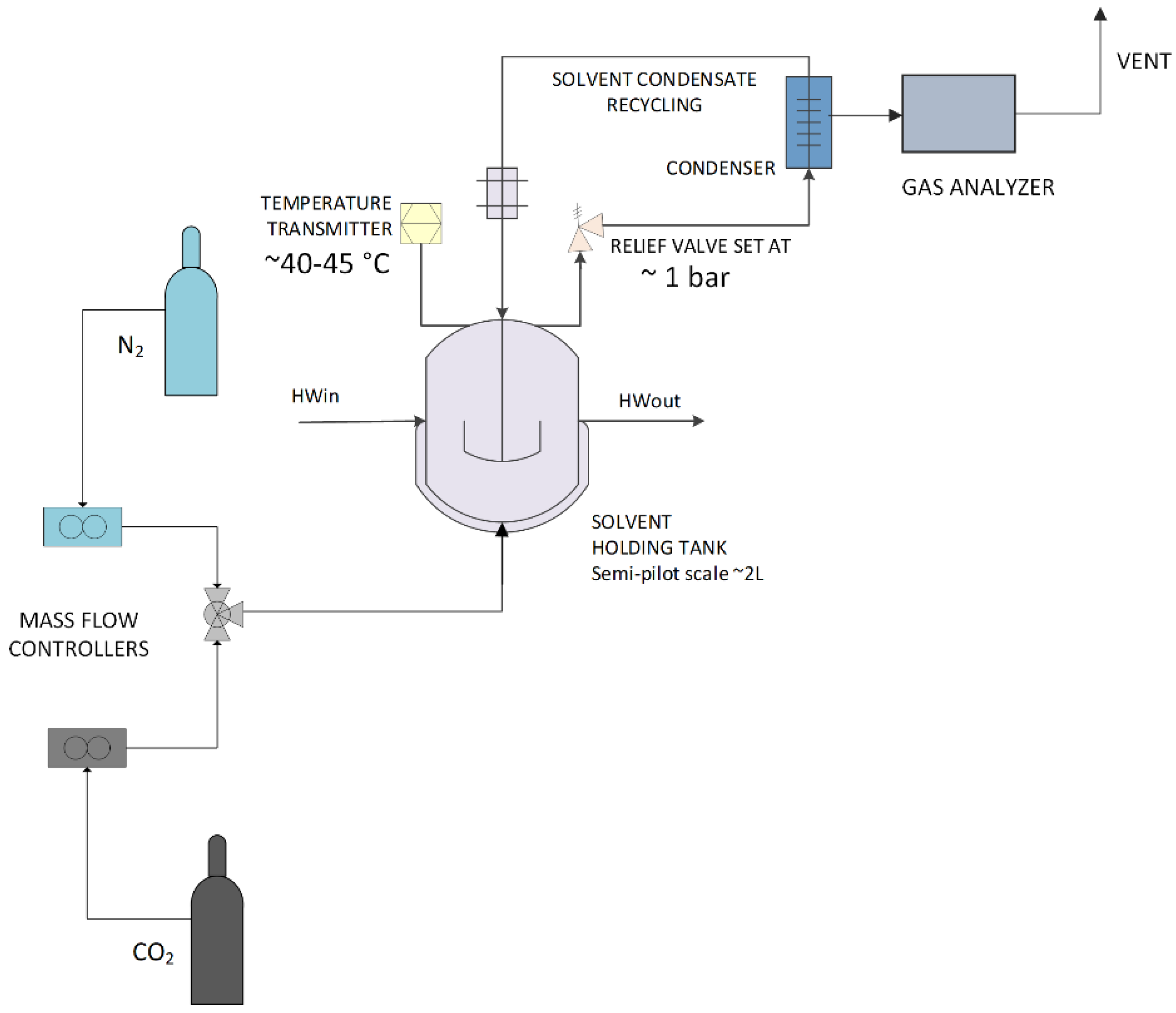
2. Material and Methods

Two stainless steels (SS), SS 316L and SS 304L, were used in this study. Their chemical composition is reported in Table 1 as acquired by XRF analysis (X-ray Fluorescence).
Both SS alloys were acquired in cylindrical form, having a diameter of 12 mm. Prior to electrochemical testing all specimens were mechanically processed by grinding (using a silicon carbide (SiC) paper 1000-grit) and then cleaned with ethanol in an ultrasonic bath to ensure that the specimen surface does not affect the measured corrosion properties.
An aqueous solution of 30 wt.% MEA was prepared from a 99% MEA reagent and deionized (DI) water. The CO2 loading was 0.50 ± 0.01 mol CO2/mol MEA while the corrosion behavior was evaluated in three different temperatures of 25 °C, 40 °C and 80 °C. Due to its widespread application in gas treatment facilities and post–combustion CO2 collection units, MEA was selected as a reference for CO2 absorption solvents [2,5,18,19,23]. Figure 1 depicts the procedure followed to load the MEA solutions. More specifically, for the preparation of the loaded MEA solutions a 2 L stirred vessel, equipped with a heating mantel was used. The temperature and gas phase concentration were monitored online. A batch of fresh aqueous MEA 30 wt.% solution (1200 g) was prepared and loaded in the vessel, where it was degassed with N2 and stirred until reaching the targeted temperature. Then, a gas mixture CO2/N2 of controlled flow (3 L/min total) and concentration (12–25 vol.%) was fed from the bottom of the vessel until equilibrium was achieved. Equilibrium is considered when the exiting gas concentration is equal to the entering one, as monitored by the NDIR gas analyzer. Samples of the liquid phase were collected for analysis. CO2 loading is measured by barium chloride titration method and total amine concentration is measured by acid-base titration. The loaded MEA solution was then used for the corrosion experiments.
A traditional three-electrode cell was used for all electrochemical tests. The reference electrode was a saturated calomel electrode (SCE), and the auxiliary (counter) electrode was a platinum rod. During the experiments, the unloaded and loaded MEA solutions were sealed in glass containers and kept at a constant temperature of 25 °C, 40 °C, and 80 °C without using any purging gas.
Prior to conducting each electrochemical corrosion experiment the open circuit potential (OCP) of the specimens was determined. To achieve a steady condition, OCP values were recorded for 180 min. A scanning rate of 0.5 mV s−1 was used for all polarization measurements from –600 to +900 mV (versus SCE) with respect to the OCP value. Cyclic polarization measurements were performed, also using a scanning rate of 0.5 mV s−1 from –600 to +900 mV (versus SCE) with respect to the OCP value. The potential was reversed when it reached about 900 mV (versus SCE), when it was evident that there was no hysteresis, or until the hysteresis loop closed (in curves with clear hysteresis). Tafel extrapolation was used to determine corrosion current densities. An acceptable level of accuracy was achieved by adhering to a number of criteria, which were detailed in [24]. Corrosion density values were estimated and normalized to the surface area of each sample. EIS was performed at OCP (EOCP) in the frequency range of 10 kHz to 0.1 Hz with a peak–to–peak voltage excitation of 10 mV. To assess reproducibility, all electrochemical tests were repeated three times.
To investigate the variations in corrosion behavior of the SS 304L and SS 316L in unloaded MEA solution and loaded MEA solution and elucidate a corrosion mechanism, SEM along with EDS analyses were utilized to characterize the corroded samples after electrochemical testing.

3. Results and Discussion

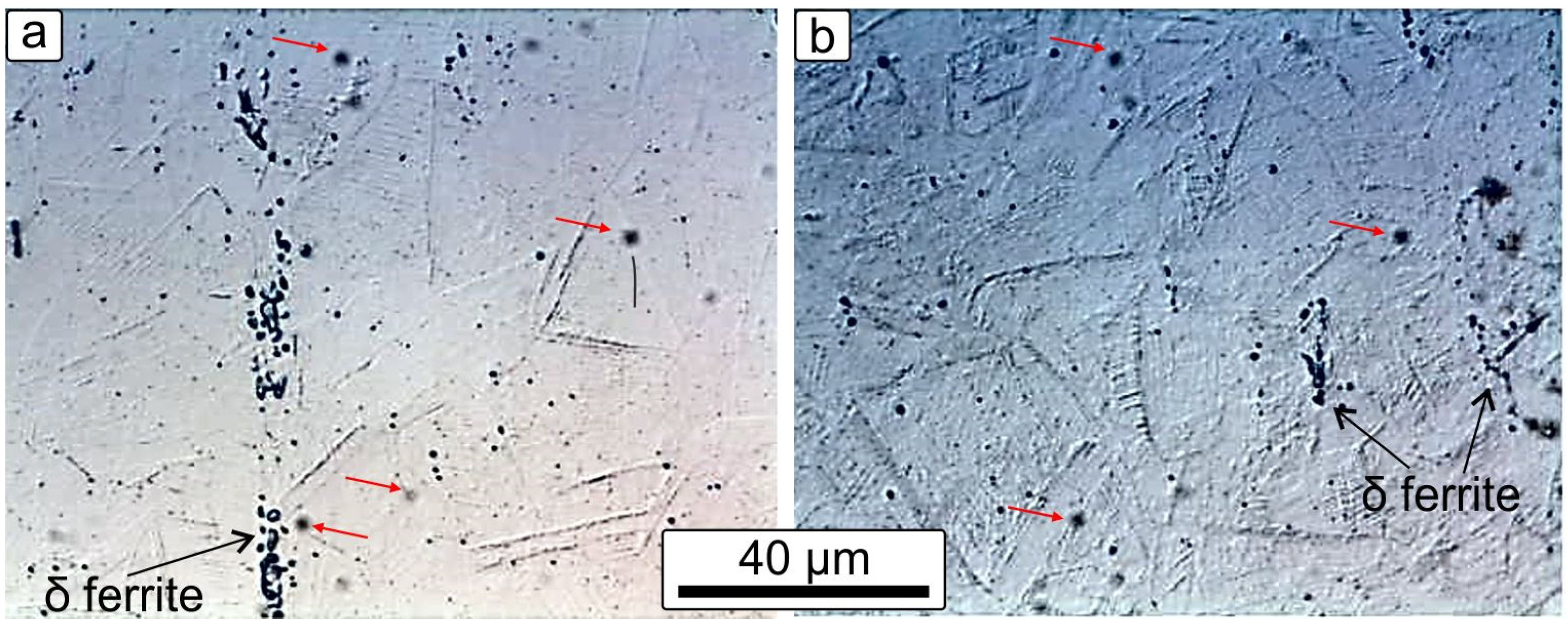
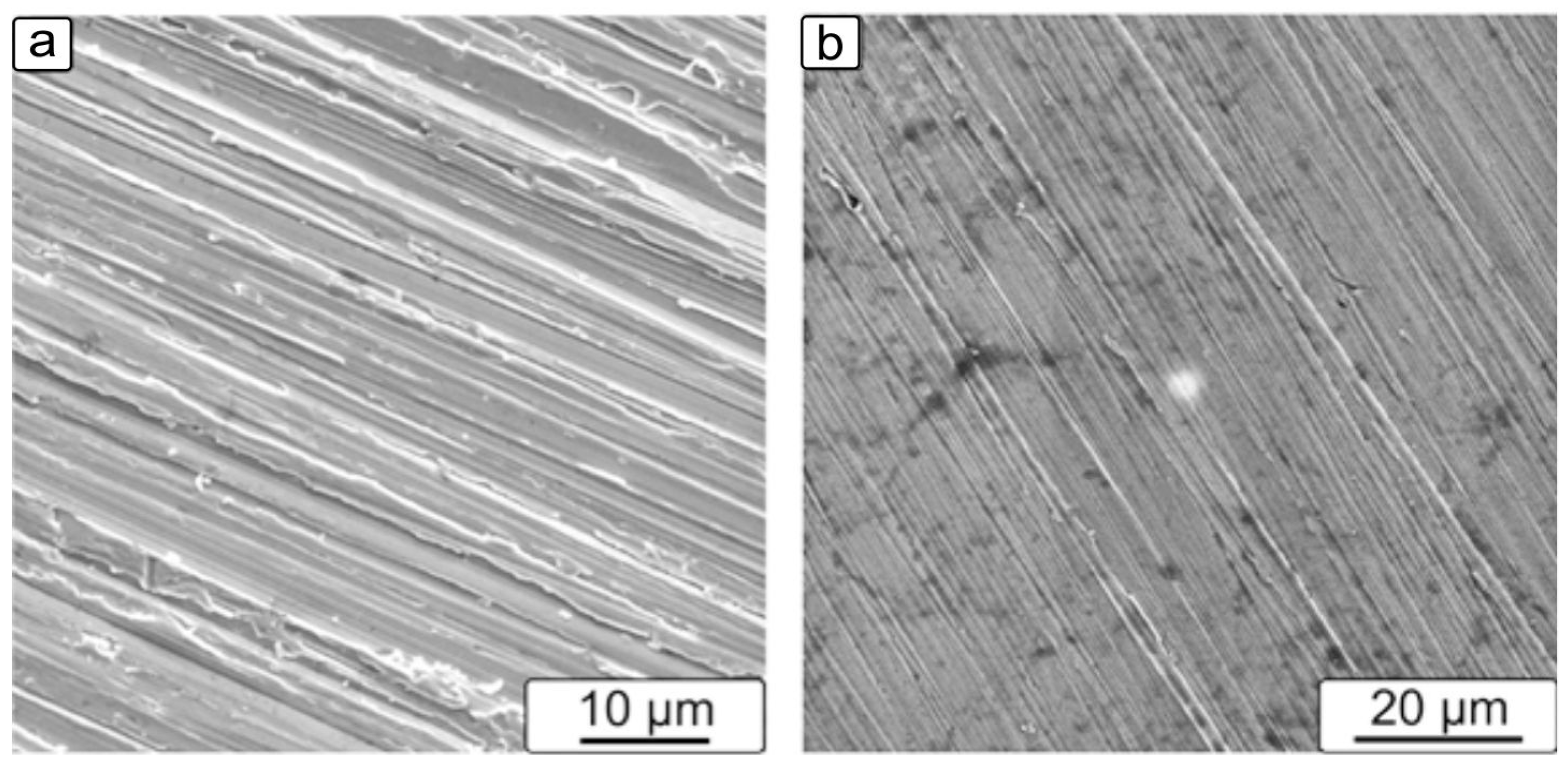
3.1. Microstructure of the SS Used

The microstructure of the initial SS 304L and SS 316L material used is shown in Figure 2. Fine, equiaxed austenitic grains are visible along with δ ferrite stringers and some carbides precipitations (indicated with the red arrows).

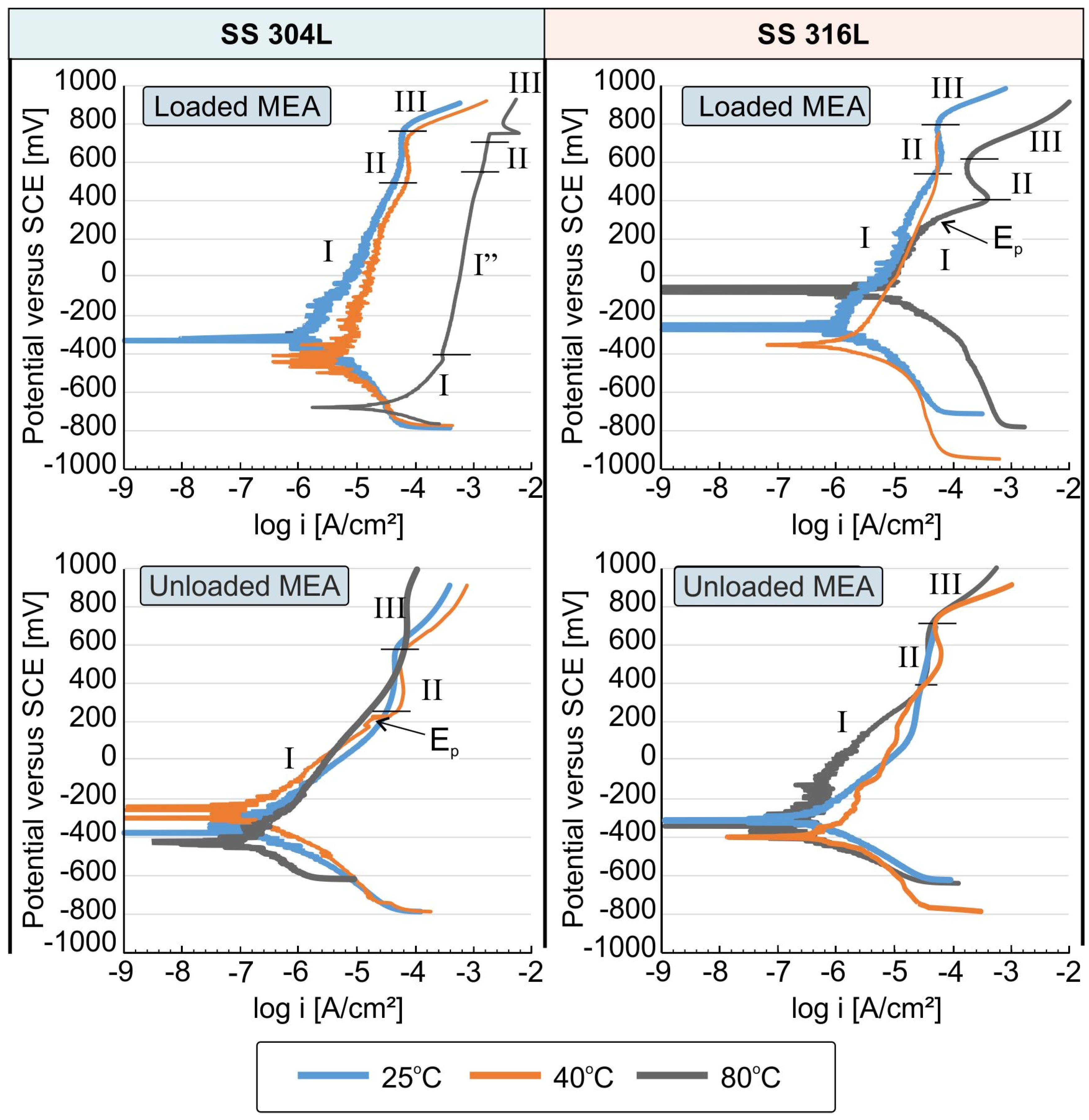
3.2. Potentiodynamic Polarization Measurements

The overall corrosion response and passivation behavior of the SS materials are evaluated using the potentiodynamic polarization technique. Figure 3 shows the potentiodynamic curves of SS 304 and SS 316 for various solution temperatures for the unloaded and loaded MEA solution.
In all the examined cases, for both materials, an active dissolution behavior is observed in the anodic polarization (region I). By increasing the potential there is a shift from a highly active dissolution to a less active dissolution (region where the current stabilizes and is voltage independent, region II). Region II can be characterized as a pseudo-passive area in which a corrosion layer may exist which is either too small in thickness or discontinuous or less stable resulting in insufficient protection against corrosion. The dissolution rate is probably reduced owning to the deposition or absorption of the corrosion products on the surface of the SS which act as a barrier film. It is well documented that primary amines such as MEA are prone to oxidation degradation and that the degraded MEA products can be physically or chemically absorbed to the SS surface [13].
Additionally, any differences detected in the corrosion potential (Ecorr) between the same SS and MEA solution with respect to the temperature can be attributed to the nature of MEA and the thermal degradation of MEA that was also confirmed by color change of the MEA solution (becoming more yellow). The differences of corrosion potential (Ecorr) in the loaded MEA solution are observable in both materials, indicating that the loaded MEA is more sensitive to temperature alterations.
It is well documented that, in aqueous amine solutions loaded with CO2, the corroding components that participate in reduction processes (cathodic reactions) are H2O and degradation products of MEA, such as carbamate and protonated amine. In water solutions, carbamate anion usually dissolve to produce carbonate or bicarbonate, according to Equations (1) and (2), that can potentially react with the Fe of the SS [2,5,6,13,20].
H2NCOO + 2H2O↔NH4+ + HCO3 + HO
2H2NCOO + 2H2O↔2NH4+ + 2CO32−
The increasing corrosiveness of loaded MEA resulting from the rise in solution temperatures could be explained by reactions (1) and (2) together with other possible reactions such as the dissociation of protonated amine. The thermal degradation of the loaded MEA results in higher kinetics of the cathodic reactions at higher temperatures, therefore causing an acceleration of the corrosion process through metal dissolution as indicated by the increase of the anodic currents in higher temperatures. The cathodic shift in Ecorr values is in agreement with the acceleration of the dissolution of iron at higher temperatures. On the other hand, the variations of corrosion potential (Ecorr) in unloaded MEA solution for each material are negligible, indicating limited thermal degradation of unloaded MEA.
For both materials, at each temperature we have a shift of the polarization curves to higher currents when the loaded MEA is used, indicating reduced corrosion resistance. In this case the polarization curves when using loaded-MEA show a slightly higher current in the pseudo-passive region when increasing amine temperature from 25 °C to 40 °C. A pronounced increase in the current of the pseudo-passive region is obvious in loaded MEA solutions for both materials at 80 °C. The sharpest increase in current in region III (Figure 3) is most likely associated with the onset of transpassive dissolution probably due to dissolution of Cr2O3 oxide [25]. The fact that the corrosion potential shifts to more negative values when the amine solution is loaded and that the pseudo-passive region is significantly lower for all loaded amine temperatures is again an indication of a higher tendency for corrosion and a lower ability to form protective layers. Exception to this observation is for the SS 316L at 80 °C, where a more noble Ecorr is observed. All of the above observations lead to the conclusion that the overall behavior of SS 304L and SS 316L can be characterized as presenting significantly lower corrosion resistance when the amine is loaded with CO2.
Finally, for the SS 304L a pitting tendency (indicated by the Ep) may be observed only for the unloaded MEA at 40 °C and for the SS 316L this can be observed for the loaded MEA at 80 °C. Nevertheless, since this is only an indication and no clear pitting potential can be deduced, cyclic polarization was used for determining any tendency to local corrosion.
Figure 4 shows the corrosion rate for SS 304L and SS 316L at 25 °C, 40 °C and 80 °C when immersed in unloaded and loaded MEA solution. For the case of SS 304L tested in unloaded MEA solution, the temperature rise does not affect the corrosion rate. The values in all three temperatures are quite low, indicating good corrosion resistance of SS 304L steel in the case of unloaded MEA solution. The SS 316L appears to have higher corrosion rates with respect to the SS 304L in the unloaded MEA solution. The temperate rise seems to affect the corrosion rate for the SS 316L in unloaded MEA solution. However, when the temperature is increased at 80 °C, an abrupt decrease of corrosion rate was observed, which is probably related to a more stable formation of a protective film. The fact that the SS 316L has inferior corrosion properties when immersed in unloaded MEA could be attributed to the microstructure of the SS 316L (Figure 2a). The presence of the ferrite stringers is more intense in the SS 316L and they seem to act as initial preferential dissolution points. Additionally, the anodic Tafel slopes are higher for the SS 316L with respect to SS 304L in unloaded MEA solutions at 25 °C and 40 °C, leading to higher anodic dissolution rates. This behavior can be linked to the larger coverage of the surface of the SS 316 L, with absorbed corrosion products presenting an elongated shape that resembles the shape of the ferrite stringers (as discussed later in Section 3.5 and shown in Figure 8c,e).
For the SS 304L when tested under loaded MEA solution, the corrosion rate increased significantly with increasing temperature of the amine solution. More specifically, the corrosion rate is almost doubled with the increase of the solution temperature from 25 °C to 40 °C and is quadrupled when the solution temperature is 80 °C. The values of the corrosion rates (Figure 4) are significantly higher when a loaded amine is used for each temperature, demonstrating that the loaded amine is an important corrosive factor in relation to the unloaded amine for the SS 304L. For the SS 316L, in loaded MEA solution, the increase of temperature also increases the corrosion rate, whilst for solution temperature of 25 °C, the loading plays no role in the SS 316L More specifically, the corrosion rate triples with an increase in temperature to 40 °C. Additionally, a sixfold increase is observed in the corrosion rate of SS 316L with the rise of the solution temperature of loaded MEA to 80 °C. Nevertheless, the overall corrosion rates of SS 316L are lower with respect to the SS 304L for the same temperature under loading conditions. For the SS 304L, in loaded MEA solution, the corrosion rate was calculated to 27 μm/y at 25 °C, 49 μm/y at 40 °C and 134 μm/y at 80 °C, respectively. For the SS 316L, the corrosion rate was calculated to 8.3 μm/y at 25 °C, to 31 μm/y at 40 °C and 67 μm/y at 80 °C, respectively. Superior corrosion behavior of SS 316L is also reported in other studies when tested in aMDEA aqueous solutions [25,26].

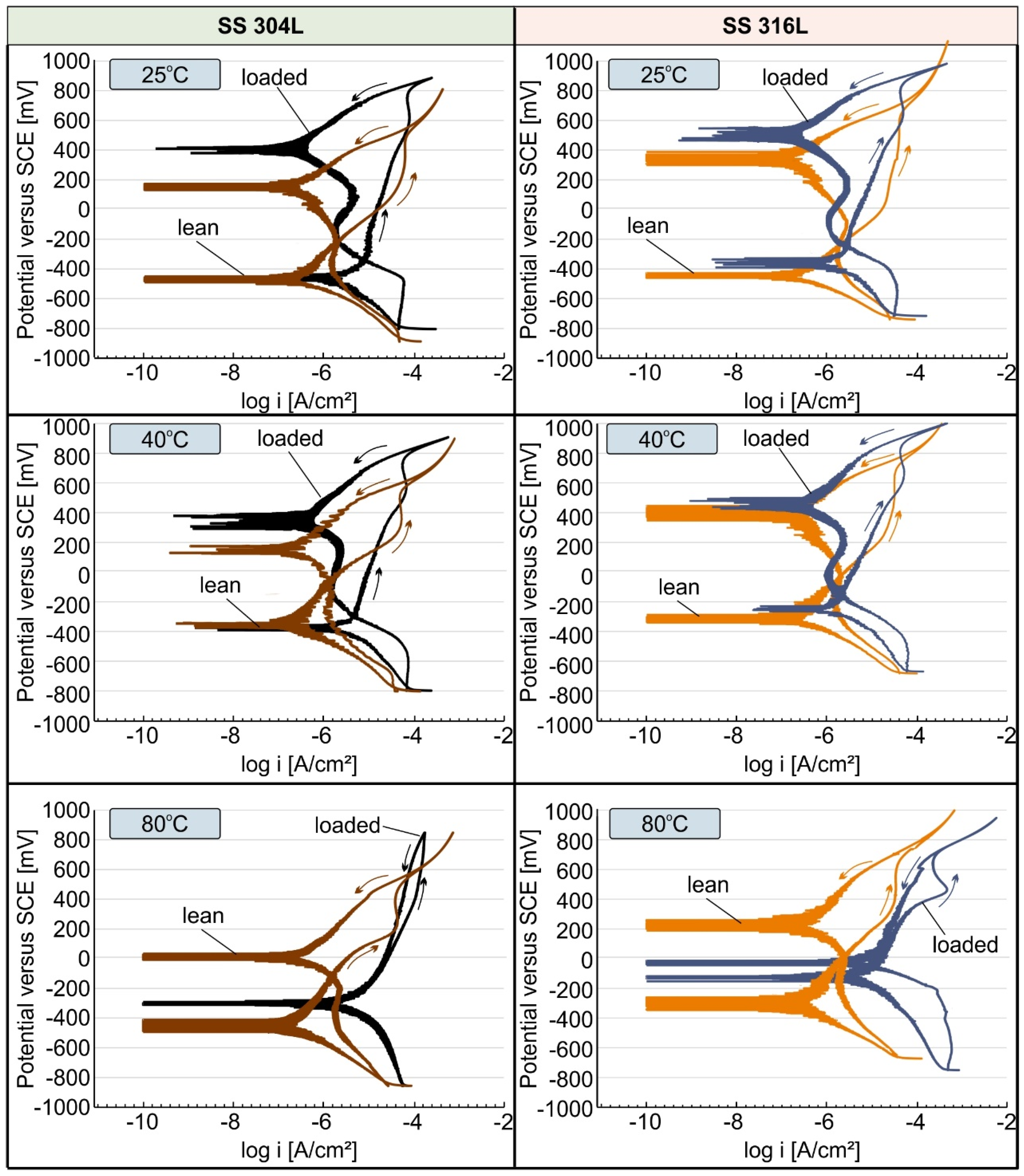
3.3. Cyclic Polarization

The cyclic polarization method was employed to assess the susceptibility and sensitivity of the 304L and 316L stainless steel samples to localized corrosion when immersed in both MEA solutions (loaded and unloaded).
Figure 5 shows the cyclic polarization curves for SS304 and SS316L at 25 °C, 40 °C, and 80 °C. The cyclic polarization curves of the samples do not differ significantly in each test solution (loaded and unloaded MEA solution) for solution temperatures of 25 °C and 40 °C. The same is observed at the temperature of 80 °C, although at this temperature for the case of the loaded MEA solution in both stainless steels the shift to smaller currents is less obvious. This is more intense for the SS 304L.
In all three temperatures, a negative hysteresis loop was observed, since the reverse scan current density is less than that of the forward scan, indicating that the SS 304L and SS 316L alloy in the exposed conditions of loaded and unloaded amine does not show a tendency for pitting corrosion (localized corrosion). Negative hysteresis indicates that a damaged passive membrane “repairs” itself and that the metastable micropores/pits that may form do not grow or become passive. This may be due to an increase in the thickness of the pseudopassive film at a higher potential resulting in reduced corrosion rates. It is reported that the more noble is the anodic to cathodic transition potential (Erp) between the forward and reverse polarization, acquired at a constant scan rate, the less prone the material is to the onset of local corrosion [27]. This observation applies to all test cases at 25 °C and 40 °C solution temperatures.
Increasing the temperature of the solutions to 80 °C resulted in a reduction in the protective properties of the pseudopassive corrosion layer formed on these metals. This in turn resulted in a shift of the 80 °C transition potential (Erp) to more active potentials. Especially in the case of SS 304L, when immersed in the loaded MEA at 80 °C the transition potential coincides with the corrosion potential of the forward polarization, which may indicate a reduced capacity for repassivation.

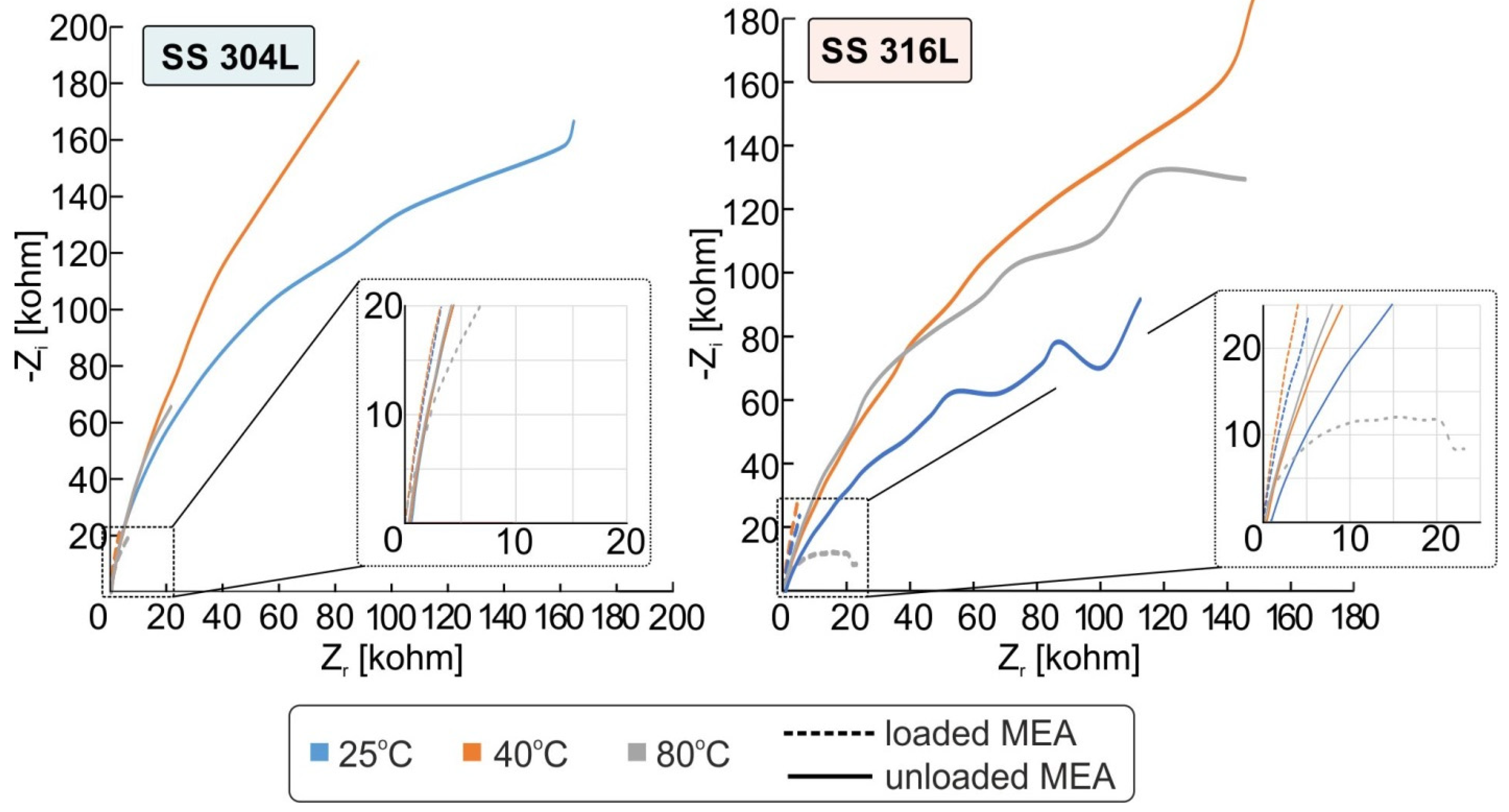
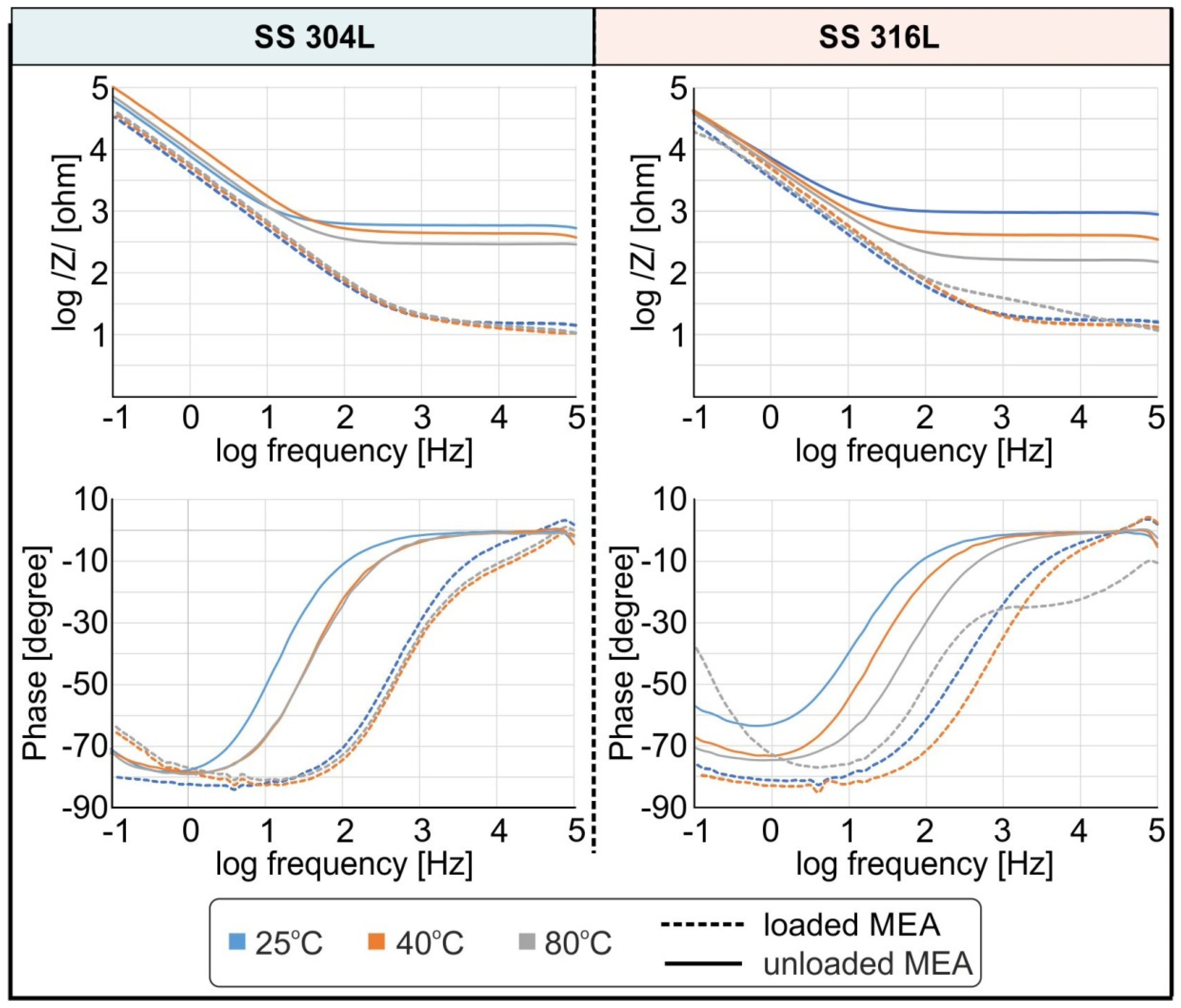
3.4. EIS Measurements

Figure 6 and Figure 7 shows the impedance plots (Nyquist) and total impedance (Bode) curves for SS 304L and SS 316L alloys in loaded and unloaded MEA solution at 25 °C, 40 °C, and 80 °C correspondingly.
The general characteristics of the Nyquist impedance curves in Figure 6 (imaginary Zi and real part Zr) do not seem to change with temperature in each tested solution. The impedance curves (imaginary Zi and real part Zr) for each sample using unloaded MEA solution form an imperfect semicircle. The absence of perfect semicircles at very high frequencies (kHz range) in the impedance diagrams may be related to the formation of surface layers of corrosion products of relatively minimal thickness. Nyquist diagrams of all samples in loaded MEA solution show straight lines, which may be attributed to diffusion related reactions together with absorption processes of corrosion intermediates on the surface of the samples. In addition, any observed decrease in Zi and Zr impedance values for the samples tested in loaded MEA solution compared to the unloaded amine is correlated with a rise in corrosion rates, which is consistent with the results presented from the polarization measurements.
In general, any decrease in (Zi and Zr), with a consequent increase in corrosion currents, can be explained by generally considering that this decrease: (i) is related to active charge-transfer reactions in the generated interface between solution and metallic material (ii) and/or the absence or unsatisfactory formation of any layer of reaction products (a protective layer) which may improve the corrosion resistance of the material [28,29]. The Nyquist impedance arc radius of the tested materials in loaded MEA solution is notably smaller than that in unloaded MEA at all tested temperatures, indicating that the loading of the MEA solution contributes pronouncedly in the corrosion process. This is consistent with the results obtained for the polarization experiments
As for the Bode curves (Figure 7), for each case under study, at high frequencies they approach a constant value. For both SS used, this limit of resistance at high frequencies appears to increase significantly when the unloaded MEA solution is used at any solution temperature, indicating possibly better corrosion resistance of the stainless steel when the amine solution is unloaded. In general, the impedance measurement diagrams show characteristics, in the analyzed frequency range, which are related to the development of passivation films and local corrosion (kHz band), the total corrosion rate (Hz band), and the adsorption of corrosion intermediates (mHz band) [28,29].
From the Bode curves (Figure 7), it appears that at low frequencies (<0.2 Hz) the total impedance (/Z/) does not approach a clear dc limit, except for SS 316L when tested in loaded MEA at 80 °C. The clear DC limit observed for the SS 316L at loaded MEA and 80 °C indicated the absence of an active diffusion mechanism. The higher phase angle at low frequencies in the corresponding Bode plot also attested this deduction.
The slope of the total impedance–frequency curve for all the other cases remains unchanged at low frequencies, resulting in a steady rise of the total impedance without approaching a clear DC limit. The continuous rise of the total impedance at low frequencies suggests that a diffusion-related mechanism exists that controls electrochemical reactions. The deflection of phase angle from −90° and the fact that the maximum phase is located in a medium–low frequency region is also an indication that the protective layer form is permeable to ions, and is therefore considered defective [28,29]. Additionally, from Figure 7, the total impedance is reduced when a loaded amine solution is used. Finally, for each test sample, the total impedance at high frequencies is lower since at these frequencies the diffusion of ions does not contribute significantly to impedance. However, for the unloaded MEA solution, the total impedance at high frequencies is considerably higher. This frequency region is linked with the electrolyte resistance and formation of passivation film. Therefore, we can assume that the in all cases the unloaded MEA either provided better conditions for passivation or is less corrosive.

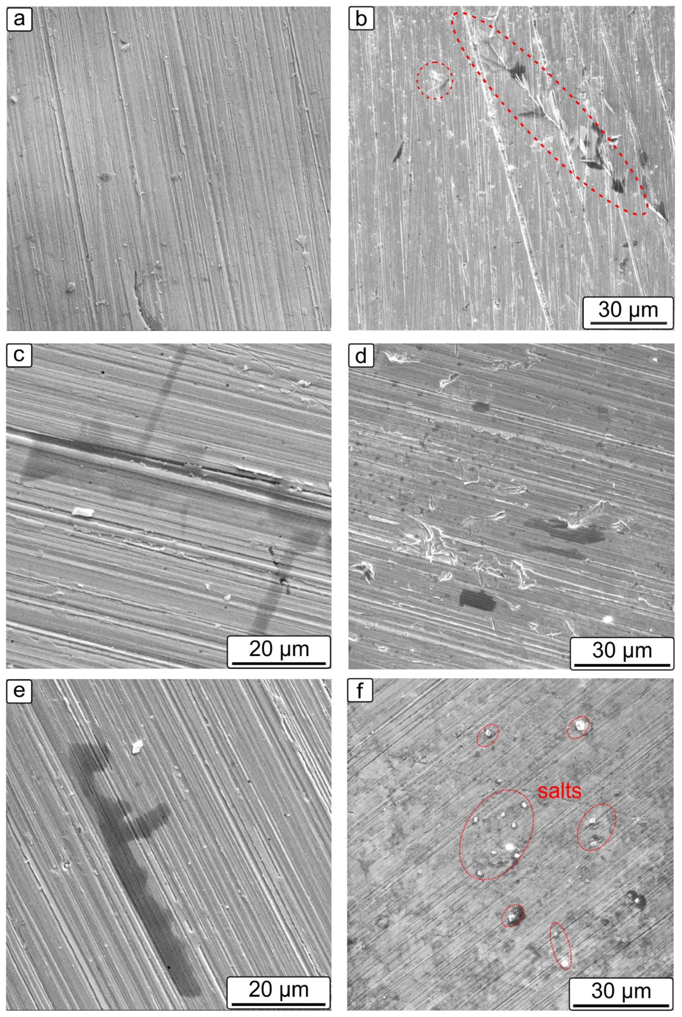
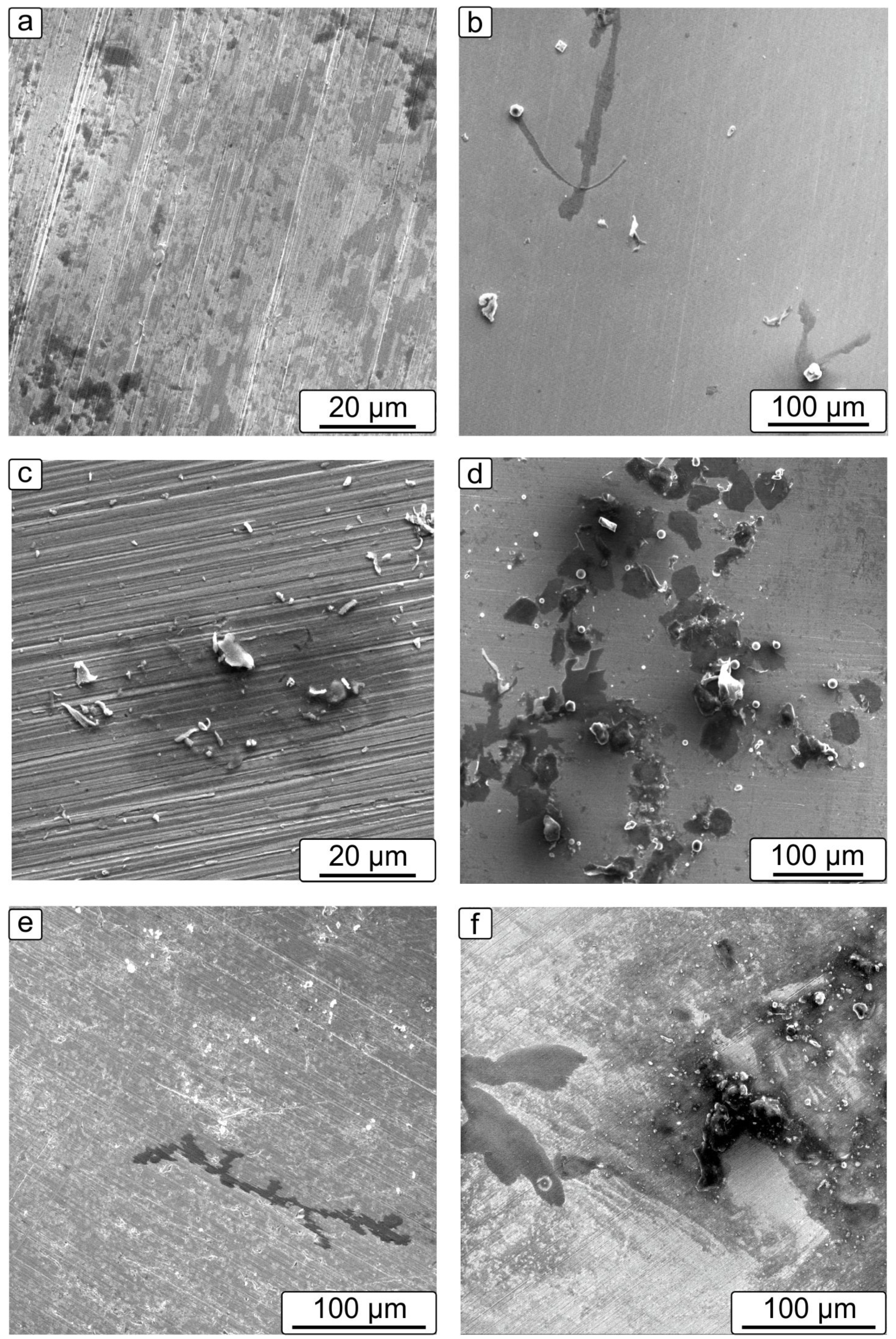
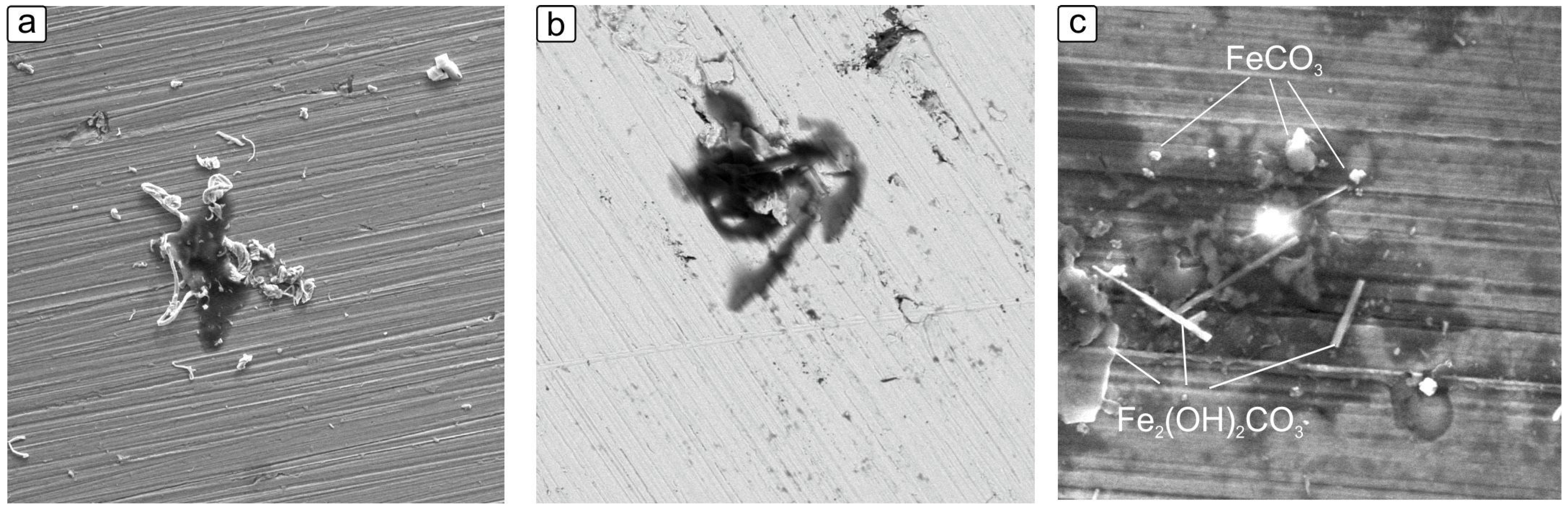
3.5. Microstructural Observation of the Corroded Samples

Surface characterization by SEM and EDS were performed on the corroded samples to better understand the impact of CO2 loading and temperature on corrosion. The corroded samples were obtained after the potentiodynamic polarization testing. Figure 8 shows SEM images for SS 316L (a, c and e) and SS 304L (b, d and f) when immersed in unloaded MEA solution. SEM images of SS 316L and SS 304L prior corrosion testing are also reported in Figure 9 for reasons of comparison.
Figure 8a depicts an indicative microstructure of the SS 316L after potentiodynamic polarization corrosion testing in unloaded MEA at 25 °C. The microstructure of the sample is similar to the pristine one of the SS 316L (Figure 9a), thus indicating that little or no corrosion damage took place. For the SS 304L tested under the same conditions plate-shaped crystals at the surface were apparent is some regions (often shown as black regions probably due to shading effect in the images), marked with red dotted circles in Figure 8b. These regions are ascribed probably to the formation oxide layers or to absorption of corrosion products produced during MEA degradation. EDS analysis of these regions indicated increased oxygen content with some carbon content. However, it should be mentioned that with EDS analysis can give only an indication, since it cannot accurately capture the oxygen and carbon contents due the low atomic mass of such atoms. The possibly occurring reactions for the oxide formation may be according to the Equations (3) and (4) [20,30]:
Fe + 2H2O → Fe(OH)2 + 2H+ + 2e
Fe + H2O → FeO + 2H+ + 2e
For the SS 316L the increase of the temperature at 40 °C (Figure 8c) and 80 °C (Figure 8e) provoked an increase in the surface coverage of the steel with black layers of oxide or absorbed corrosion products presenting an elongated shape. However, the thickness of this layer is small since the original underneath surface is still visible and the coverage of the steel surface is also in small extent, indicating that the formed layer cannot be considered as a protective one. This observation is consistent with the polarization results. Nevertheless, corrosion products were not detectable on the surface of both samples. For the SS 304L the increase of the temperature at 40 °C resulted in the appearance of some pits (Figure 8d), which is consistent with the potentiodynamic polarization test. However, the extent of the pitting was very limited. At temperatures of 80 °C the SS 304L alloy presented some precipitated compounds which were attributed to salts rich in Ca and chloride as defined by EDS analysis (Figure 8f). The appearance of these type of salts is due to contaminated make-up water during the MEA production and usually result in amine degradation and can lead to increased corrosion rate [9].
Figure 10a,b depicts SEM images of the microstructure of the SS 316L and SS 304L alloy correspondingly after potentiodynamic polarization corrosion testing in CO2−loaded MEA solution at 25 °C. The SS 304L alloy precipitates can be observed along with regions covered by a black corrosion product layer (rich in oxygen and cardon) having an elongated shape (Figure 10b). No precipitates were observed the SS 304L alloy (Figure 10a).
With the increase in the temperature to 40 °C and 80 °C, numerous nodules as well as blade-shaped clusters were detected for both SS 316L (Figure 10c,e, respectively) and SS 304L alloys, covering an extended region in the case of SS 304L (Figure 10d,f). Salts were also precipitated in the case of loaded MEA solution at the surface of both SS alloys when elevated temperature were used (40 °C and 80 °C). A representative image is shown in Figure 11a (mixed with corrosion or absorption product layer). Nodules exhibited a spheroid shape and polygonal shape clusters corresponded to FeCO3 phase as identified by EDS analysis whereas the plate-like corrosion product was rich in oxygen and was ascribed to Fe2(OH)2CO3 phase. Such phases were also reported in literature for steels [31,32,33]. A higher magnification image of such a plate-like product is shown in Figure 11b in a back-scattered mode SEM image. The FeCO3 is known to act as a protective layer for corrosion. From the SEM images it can be deduced that the formation of the iron carbonate nodules takes place on or near the black corrosion layer which is ascribed to oxide layer or absorbed degradation corrosion product from MEA (Figure 11c). This observation was also reported in [34] for the corrosion of iron by geothermal water rich in CO2. The proposed corrosion possible reactions are Equations (5) and (6) [34]:
Fe(OH)2 + H2CO3 → FeCO3 + 2H2O
Fe(OH)2 + HCO3 + H+ → FeCO3 + 2H2O
The formation of siderite (FeCO3) is known to act as a protective layer for corrosion. However, the formed nodules seem not be tightly adhering to the surface of both SS alloys. Therefore, they cannot be considered as a passive film, which can explain the rise in the corrosion rate with the temperature increase or the CO2 loading.

4. Conclusions

Electrochemical techniques were used to evaluate the corrosion performance of two stainless steels, 316L and 304L, tested in unloaded and loaded with CO2 MEA aqueous solutions. The following conclusions are deduced from the above study:
(1)
The SS 316L performs better in the loaded conditions with respect to the SS 304L. On the contrary, the SS 304L has superior corrosion properties when immersed in unloaded MEA showing extremely low corrosion rates.
(2)
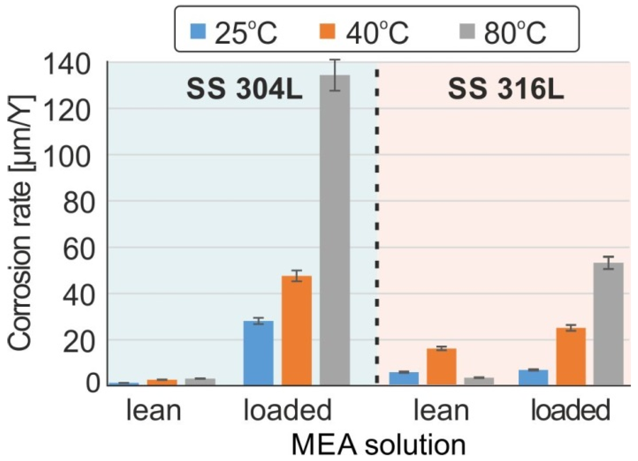
The temperature rise has adversely affected the corrosion properties of both materials when the loaded MEA was used. More specifically, for the SS 304L, the corrosion rate was calculated to 27 μm/y at 25 °C, 49 μm/y at 40 °C, and 134 μm/y at 80 °C, respectively. For the SS 316L, the corrosion rate was calculated to 8.3 μm/y at 25 °C, to 31 μm/y at 40 °C and 67 μm/y at 80 °C, respectively. The increase of temperature does not essentially influence the corrosion rate of both materials when unloaded MEA is used. The thermal degradation of loaded MEA solution was believed to be the main reason for the accelerated corrosion rates with temperature increase.
(3)
Microstructural characterization revealed corrosion product depositions in both SS alloys when loaded MEA is used. The formation of a mixture layer of phases ascribed to Fe2(OH)2CO3 and FeCO3 without being protective layer was observed in both SS alloys. The precipitated corrosion products in loaded MEA solutions indicate the degradation of the MEA during loading.

Author Contributions

Conceptualization, F.S. and N.M.; methodology, F.S. and E.N.; software, C.F. and A.B.; validation, C.F., A.B. and F.S.; formal analysis, A.B.; investigation, C.F. and A.B.; resources, N.M.; data curation, C.F. and A.B.; writing—original draft preparation, A.B. and F.S.; writing—review & editing, F.S.; visualization, N.M.; supervision, N.M.; project administration, A.I.P.; funding acquisition, P.S. All authors have read and agreed to the published version of the manuscript.

Funding

This research has been financed by the European Union and Greek National Funds through the Operational Program Competitiveness, Entrepreneurship and Innovation, under the call Research-Create-Innovate, Project T2EΔK-01911.

Institutional Review Board Statement

Not applicable.

Informed Consent Statement

Not applicable.

Data Availability Statement

Data sharing not applicable.

Conflicts of Interest

The authors declare no conflict of interest.

References

  1. Madejski, P.; Chmiel, K.; Subramanian, N.; Kuś, T. Methods and Techniques for CO2 Capture: Review of Potential Solutions and Applications in Modern Energy Technologies. Energies 2022, 15, 887. [Google Scholar] [CrossRef]
  2. Hjelmaas, S.; Storheim, E.; Flø, N.E.; Thorjussen, E.S.; Morken, A.K.; Faramarzi, L.; de Cazenove, T.; Hamborg, E.S. Results from MEA amine plant corrosion processes at the CO2. Energy Procedia 2017, 114, 1166–1178. [Google Scholar] [CrossRef]
  3. Krzemień, A.; Więckol-Ryk, A.; Smoliński, A.; Koteras, A.; Więcław-Solny, L. Assessing the risk of corrosion in amine-based CO2 capture process. J. Loss Prev. Process Ind. 2016, 43, 189–197. [Google Scholar] [CrossRef]
  4. Kazepidis, P.; Papadopoulos, A.I.; Tzirakis, F.; Seferlis, P. Optimum design of industrial post-combustion CO2 capture processes using phase-change solvents. Chem. Eng. Res. Des. 2021, 175, 209–222. [Google Scholar] [CrossRef]
  5. Xiang, Y.; Yan, M.; Choi, Y.-S.; Young, D.; Nesic, S. Time-dependent electrochemical behavior of carbon steel in MEA-based CO2 capture process. Int. J. Greenh. Gas Control 2014, 30, 125–132. [Google Scholar] [CrossRef]
  6. Emori, W.; Jiang, S.L.; Duan, D.L.; Ekerenam, O.O.; Zheng, Y.G.; Okafor, P.C.; Qiao, Y.X. Corrosion behavior of carbon steel in amine-based CO2 capture system: Effect of sodium sulfate and sodium sulfite contaminants. Mater. Corros. 2017, 68, 674–682. [Google Scholar] [CrossRef]
  7. Hamah-Ali, B.; Ali, B.S.; Yusoff, R.; Aroua, M.K. Corrosion of Carbon Steel in Aqueous Carbonated Solution of MEA/bmimDCA. Int. J. Electrochem. Sci. 2011, 6, 181–198. [Google Scholar]
  8. Veawab, A.; Tontiwachwuthikul, P.; Chakma, A. Corrosion Behavior of Carbon Steel in the CO2 Absorption Process Using Aqueous Amine Solutions. Ind. Eng. Chem. Res. 1999, 38, 3917–3924. [Google Scholar] [CrossRef]
  9. Verma, N.; Verma, A. Amine system problems arising from heat stable salts and solutions to improve system performance. Fuel Process. Technol. 2009, 90, 483–489. [Google Scholar] [CrossRef]
  10. Zheng, L.; Matin, N.S.; Thompson, J.; Landon, J.; Holubowitch, N.E.; Liu, K. Understanding the corrosion of CO2-loaded 2-amino-2-methyl-1-propanol solutions assisted by thermodynamic modeling. Int. J. Greenh. Gas Control 2016, 54, 211–218. [Google Scholar] [CrossRef] [Green Version]
  11. Li, X.; Pearson, P.; Yang, Q.; Puxty, G.; Feron, P.; Xiao, D. A study of designer amine 4-amino-1-propyl-piperidine against the corrosion of carbon steel for application in CO2 capture. J. Greenh. Gas Control 2020, 94, 102929. [Google Scholar] [CrossRef]
  12. Rennie, S. Corrosion and materials selection for amine service. Inst. Mater. Eng. Australas. 2006, 30, 126–130. [Google Scholar]
  13. Ooi, Z.L.; Tan, P.Y.; Tan, L.S.; Yeap, S.P. Amine-based solvent for CO2 absorption and its impact on carbon steel corrosion: A perspective review. Chin. J. Chem. Eng. 2020, 28, 1357–1367. [Google Scholar] [CrossRef]
  14. Tanthapanichakoon, W.; Veawab, A.; McGarvey, B. Electrochemical Investigation on the Effect of Heat-stable Salts on Corrosion in CO2 Capture Plants Using Aqueous Solution of MEA. Ind. Eng. Chem. Res. 2006, 45, 2586–2593. [Google Scholar] [CrossRef]
  15. Veawab, A.; Tontiwachwuthikul, P.; Chakma, A. Investigation of Low-Toxic Organic Corrosion Inhibitors for CO2 Separation Process Using Aqueous MEA Solvent. Ind. Eng. Chem. Res. 2001, 40, 4771–4777. [Google Scholar] [CrossRef]
  16. Javidi, M.; Ghassemi, A.; Lalehparvar, M.M. Amine corrosion and amine cracking of API 5L X52 carbon steel in the presence of hydrogen sulphide and carbon dioxide. Corros. Eng. Sci. Technol. 2017, 52, 510–519. [Google Scholar] [CrossRef]
  17. Xiang, Y.; Choi, Y.-S.; Yang, Y.; Nešić, S. Corrosion of Carbon Steel in MDEA-Based CO2 Capture Plants Under Regenerator Conditions: Effects of O2 and Heat-Stable Salts. Corrosion 2015, 71, 30–37. [Google Scholar] [CrossRef] [Green Version]
  18. Gunasekaran, P.; Veawab, A.; Aroonwilas, A. Corrosivity of Single and Blended Amines in CO2 Capture Process. Energy Procedia 2013, 37, 2094–2099. [Google Scholar] [CrossRef] [Green Version]
  19. Gunasekaran, P.; Veawab, A.; Aroonwilas, A. Corrosivity of Amine-Based Absorbents for CO2 Capture. Energy Procedia 2017, 114, 2047–2054. [Google Scholar] [CrossRef]
  20. Soosaiprakasam, I.R.; Veawab, A. Corrosion and polarization behavior of carbon steel in MEA-based CO2 capture process. Int. J. Greenh. Gas Control 2008, 2, 553–562. [Google Scholar] [CrossRef]
  21. Javidi, M.; Lalehparvar, M.M.; Ghassemi, A. The Effect of Temperature and Acid Gas Loading on Corrosion Behavior of API 5L X52 Carbon Steel in Amine Unit. J. Mater. Eng. Perform. 2016, 25, 1794–1801. [Google Scholar] [CrossRef]
  22. Hamada, M.F.; Zewail, T.M.; Farag, H.A. Study of corrosion behaviour of A106 carbon steel absorber for CO2 removal in amine promoted hot potassium carbonate solution (Benfield solution). Corros. Eng. Sci. Technol. 2013, 49, 209–218. [Google Scholar] [CrossRef]
  23. Kittel, J.; Idem, R.; Gelowitz, D.; Tontiwachwuthikul, P.; Parrain, G.; Bonneau, A. Corrosion in MEA units for CO2 capture: Pilot plant studies. Energy Procedia 2009, 1, 791–797. [Google Scholar] [CrossRef] [Green Version]
  24. Lekatou, A.; Sfikas, A.K.; Petsa, C.; Karantzalis, A.E. Al-Co Alloys Prepared by Vacuum Arc Melting: Correlating Microstructure Evolution and Aqueous Corrosion Behavior with Co Content. Metals 2016, 6, 46. [Google Scholar] [CrossRef] [Green Version]
  25. Panahi, H.; Eslami, A.; Golozar, M.A. Effect of heat stable acids on corrosion and stress corrosion cracking initiation of 304 and 316 stainless steels in activated methyl diethanol amine (aMDEA) solution. Corros. Eng. Sci. Technol. 2020, 55, 57–65. [Google Scholar] [CrossRef]
  26. Panahi, H.; Eslami, A.; Golozar, M. Corrosion and stress corrosion cracking initiation of grade 304 and 316 stainless steels in activated methyl diethanol amine (aMDEA) solution. J. Nat. Gas Sci. Eng. 2018, 55, 106–112. [Google Scholar] [CrossRef]
  27. Esmailzadeh, S.; Aliofkhazraei, M.; Sarlak, H. Interpretation of Cyclic Potentiodynamic Polarization Test Results for Study of Corrosion Behavior of Metals: A Review. Prot. Met. Phys. Chem. Surfaces 2018, 54, 976–989. [Google Scholar] [CrossRef]
  28. Stergioudi, F.; Vogiatzis, C.A.; Pavlidou, E.; Skolianos, S.; Michailidis, N. Corrosion resistance of porous NiTi biomedical alloy in simulated body fluids. Smart Mater. Struct. 2016, 25, 095024. [Google Scholar] [CrossRef]
  29. Stergioudi, F.; Vogiatzis, C.; Gkrekos, K.; Michailidis, N.; Skolianos, S. Electrochemical corrosion evaluation of pure, carbon-coated and anodized Al foams. Corros. Sci. 2015, 91, 151–159. [Google Scholar] [CrossRef]
  30. Mansoori, H.; Young, D.; Brown, B.; Singer, M. Influence of calcium and magnesium ions on CO2 corrosion of carbon steel in oil and gas production systems—A review. J. Nat. Gas Sci. Eng. 2018, 59, 287–296. [Google Scholar] [CrossRef]
  31. Zheng, L.; Matin, N.S.; Landon, J.; Thomas, G.A.; Liu, K. CO2 loading-dependent corrosion of carbon steel and formation of corrosion products in anoxic 30 wt.% monoethanolamine-based solutions. Corros. Sci. 2016, 102, 44–54. [Google Scholar] [CrossRef] [Green Version]
  32. Campbell, K.L.S.; Zhao, Y.; Hall, J.J.; Williams, D. The effect of CO2-loaded amine solvents on the corrosion of a carbon steel stripper. Int. J. Greenh. Gas Control 2016, 47, 376–385. [Google Scholar] [CrossRef] [Green Version]
  33. Ochoa, N.; Vega, C.; Pébère, N.; Lacaze, J.; Brito, J.L.; Ochoa, N.; Vega, C.; Pébère, N.; Lacaze, J.; Brito, J.L. CO2 corrosion resistance of carbon steel in relation with microstructure changes. Mater. Chem. Phys. 2015, 156, 198–205. [Google Scholar] [CrossRef] [Green Version]
  34. Banaś, J.; Lelek-Borkowska, U.; Mazurkiewicz, B.; Solarski, W. Effect of CO2 and H2S on the composition and stability of passive film on iron alloys in geothermal water. Electrochim. Acta 2007, 52, 5704–5714. [Google Scholar] [CrossRef]
Figure 1. Schematic representation for the procedure followed to load with CO2 the MEA solutions.
Cmd 03 00025 g001
Figure 2. Microstructure of (a) SS 316L and (b) SS 304L used.
Cmd 03 00025 g002
Figure 3. Polarization curves for SS 304L and SS 316L at 25 °C, 40 °C and 80 °C when immersed in unloaded and loaded MEA solution.
Cmd 03 00025 g003
Figure 4. Corrosion rate for SS 304L and SS 316L at 25 °C, 40 °C and 80 °C when immersed in unloaded and loaded MEA solution.
Cmd 03 00025 g004
Figure 5. Cyclic polarization curves for SS 304L and SS 316L at 25 °C, 40 °C and 80 °C when immersed in unloaded and loaded MEA solution.
Cmd 03 00025 g005
Figure 6. Nyquist plots for SS304 and SS316L at 25 °C, 40 °C and 80 °C when immersed in unloaded and loaded MEA solution.
Cmd 03 00025 g006
Figure 7. Bode plots for SS 304L and SS316L at 25 °C, 40 °C and 80 °C when immersed in unloaded and loaded MEA solution.
Cmd 03 00025 g007
Figure 8. SEM images for SS 316L (a,c,e) and SS 304L (b,d,f) after potentiodynamic corrosion testing in unloaded MEA solution.
Cmd 03 00025 g008
Figure 9. SEM images of SS 316L (a) and SS 304L (b) prior corrosion testing.
Cmd 03 00025 g009
Figure 10. SEM images for SS 316L (a,c,e) and SS 304L (b,d,f) after potentiodynamic corrosion testing in loaded MEA solution.
Cmd 03 00025 g010
Figure 11. Indicative SEM images for (a) salt precipitation, (b) FeCO3 nodules and (c) plate-like corrosion products ascribed to Fe2(OH)2CO3 phase.
Cmd 03 00025 g011
Table 1. Chemical composition of 316L and 304L used.
%CCrMnSiPSNiMoFe
SS 304L0.0318210.00450.038-Bal.
SS 316L0.02217.51.8-0.0030.54102Bal.
Publisher’s Note: MDPI stays neutral with regard to jurisdictional claims in published maps and institutional affiliations.

