1. Introduction
Optimum corrosion protection of post-tensioning tendons has been a priority since the beginning of this technology [
1] because tendons are crucial for durability and structural safety of concrete bridges. However, the metallic ducts of wrapped steel are not fully tight, the grouting procedure is not perfect and chloride-bearing water enters into the duct, leading to corrosion of the strands [
2]. During service life, inspection of post-tensioning structures with non-destructive testing and evaluation (NDE) methods is required as corrosion of the strands cannot be detected by visual inspection. Despite some progress, none of the existing inspection and monitoring methods allows a complete and meaningful evaluation of post-tensioning tendons in existing structures [
3,
4]. Thus, owners of structures and engineers face uncertainty regarding safety and durability of existing structures and severe damages and collapses of structures were reported worldwide [
5]; the most recent tragic event was the collapse of the Polcevera viaduct in Genoa, Italy, in 2018 [
6].
Nowadays, thanks to the introduction of corrugated polymer ducts and electrically isolated anchorages (EIT) in civil engineering practice, corrosion protected post-tensioning tendons can be constructed: polymer ducts prevent the ingress of aggressive substances into the tendons and the electrical isolation allows quality control and monitoring of the tightness of the duct. For the first time the most important structural elements, the tendons, can be easily monitored and initiation of damage can be detected early. This paper summarizes the requirements for EIT system and describes the impedance measurements for acceptance, quality control and monitoring. Examples from laboratory and field measurements of quality control and long-term monitoring are presented, highlighting the need of a joint collaboration of owner, structural engineer, contractor and post-tensioning company to fully benefit from the EIT technology in practice.
2. Electrically Isolated Tendons (EIT)
A new generation of thick-walled polymer ducts for bonded, internal tendons was developed by industry at the beginning of the 1990′s [
7] and gradually introduced in practice. These thick-walled plastic ducts for post-tensioning tendons become popular for use with curved tendons. The research work and development of thick-walled polymer ducts and their performance in practice is well documented in literature [
7]. A fib report presented the knowledge at that time and recommended specifications [
8]. The following reasons were at the beginning of corrugated polymer ducts:
- (a)
increased fretting fatigue resistance of the tendons [
9,
10],
- (b)
improved corrosion protection, especially in the case of stray currents, which is a vital aspect for railway bridges [
11],
- (c)
feasibility of electrical monitoring of the tendon during the whole service life [
12]
- (d)
reduced friction losses during stressing of the tendon,
2.1. Protection Levels
The following three categories of protection levels for post-tensioning tendons evolved from the developments carried out in Switzerland since 1995, jointly performed between industry, railway and road authorities and research. In the first pioneering Swiss guideline from 2001 [
13] and the revised guideline from 2007 [
14], the term “category” was used to describe the different post-tensioning systems. The letters a, b, and c indicated the lowest, respectively, highest protection level. In fib bulletin 33 “durability of post-tensioning tendons” [
15]—which has adopted the concept of three levels of protection of the mentioned Swiss guidelines—the term “protection level” is used instead of “category” and the letters a, b, and c were replaced with the numbers 1, 2 and 3. The highest protection level, PL3, corresponds to electrically isolated tendons.
2.2. The EIT System
The highest protection level, PL3, can be reached with fully encapsulated and electrically isolated tendons. In addition to the protection of the tendons from ingress of chloride containing water and corrosion the system is monitorable. Isolated tendons used in bridge structures have to be considered a system of many components, including thick corrugated polymer ducts, polymer couplers and trumpet, grout vents etc. (
Figure 1a) that together ensure a tight envelope that prevents ingress of water and chloride. The thick corrugated polymer duct avoids direct metallic contact between the mild steel reinforcement or supports and the high-strength steel strands. As with conventional post-tensioning, stress is still transferred from the individual posttensioned strands via wedges in an anchor head that in turn presses against a bearing plate embedded in the surrounding concrete. The anchor-bearing plate is electrically isolated from the anchor head by inserting a special electrically non-conductive isolation plate that supports the high compression forces (
Figure 1b).
2.3. System Approval
Any system to be used for post-tensioning tendons of PL2 or PL3 requirements has to pass a rigorous set of pre-qualification tests in order to be accepted for production [
16]. These involve a series of individual materials tests, followed by qualification of components that check mechanical properties, wear resistance and especially water-tightness. Finally, the assembled system has to pass qualification tests, including:
the full-scale duct system assembly must be airtight.
Water-tightness of the anchorage-duct assembly.
High electrical resistance of the duct and the duct with connector (with/without vent).
Maintaining high electrical resistance of the anchorage-duct assembly for 28 days.
2.4. Measuring Principle
The measurements of the resistance and the capacitance are performed with a hand-held LCR meter connected to the normal reinforcement in concrete on one side and the steel strands in the grouted ducts on the other (
Figure 2a). The measuring system thus includes the concrete surrounding the duct, the polymer duct (with ev. pores and defects) and grout in the duct. Both grout and concrete can be considered pure resistances in the frequency range between 100 and 1000 Hz. Instead, the polymer duct is essentially a capacitance (C
h) in parallel with a very high resistance R
h (
Figure 2b). Not fully closed grout vents and/or defects in the duct are represented by R
d, a small ohmic resistance in parallel.
2.5. Results of Laboratory Measurements
In order to study the effect of defects in the duct, laboratory impedance measurements in the full frequency range from 0.1 to 10
5 Hz were performed on grouted plastic ducts (ø 59 mm, length 1 m) embedded in concrete blocks [
17]. These tests were performed in order to acquire resistance and capacitance values in well controlled laboratory condition with defined diameters of the holes. The results (
Figure 3) have shown a very high resistance value for ducts without defects (reference), for welded and coupled ducts that essentially behave as capacitance (2.34 nF). On the contrary, the measured resistance decreased for ducts with holes: ducts with a 2 mm hole showed values <100 kΩ, ducts with a large 40 mm hole showed resistance values lower than 1 kΩ. At the measuring frequency of 1 kHz ducts with holes behave as resistance. A small electrolytic contact between grout and concrete as, e.g., an open grout vent in the concrete was found to have a resistance of 573 kΩ and a loss factor of 0.098 [
17]. As the length of the tendon in the laboratory experiments is 1 m, the measured values correspond directly to the specific capacitance (2.34 nF/m), respectively, the specific resistance value in kΩm. Performing measurements on real tendons with much higher length (m), the specific capacitance is calculated as C
spec = C
meas/m. The specific resistance values of a tendon with length m are calculated by R
spec = R
meas x m. This is clearly described in the guidelines.
3. Quality Control of Electrically Isolated Tendons
Quality control in the design stage, during handling and execution, as well as workmanship and good instruction are crucial for success. The various parties (engineer, owner, PT system supplier, contractor) should coordinate prior to and during construction. Expectations should be defined when writing the contract based on the level of risk. Note that EIT allows to verify the integrity of a tendon’s encapsulation—to protect a tendon from corrosion, the strands should be fully embedded in stable grout within the leak tight encapsulation.
3.1. Tests before Grouting the Tendons
The Swiss Guideline [
14] recommends performing several tests before grouting. Before pulling strands in the duct, said duct should be checked for deformations. To screen for incomplete seals in the connections, fog prepared from dry ice (CO
2) should be pumped through the duct. After placement is complete, the strands impedance measurements are recommended to detect short circuits (direct contact between strands and reinforcement). After concrete placing and tensioning of the strands, another EIT check is required to detect that application of prestress has not further abraded the duct or otherwise caused electric contact with the external reinforcement.
3.2. Tests after Grouting the Tendons—Acceptance Criteria
These measurements are mandatory in order to confirm the integrity of the fully constructed tendon enclosure [
14]. The resistance and the capacitance of each tendon are measured simultaneously but only the resistance is used as acceptance criteria. These measurement on each tendon are a very effective and a rapid quality control measure for installation. As a criterium, the length-normalized resistance R
l = R
meas x length [Ωm] must be applied because the measured resistance R
meas is inversely proportional to the length of the tendon. The measured resistance R
meas is influenced by the quality (porosity, water content) of the concrete and the grout; however, a high resistance ensures a continuous physical barrier against the ingress of water. The Swiss Guideline [
14] defines the acceptance criteria for the resistance readings of the EIT system,
To avoid fatigue and fretting corrosion, the criteria for resistance is R ≥ 20 Ω, in order to ensure that no direct contact between the normal reinforcement and the high-strength steel (short circuit) occurs.
Criteria for long-term monitoring is Rl ≥ 50 kΩm. This allows detecting the ingress of water (and chlorides) at eventual defects present in the duct.
Full electrical isolation with Rl ≥ 250 to 125 kΩm (according to duct diameter) is required for protection against stray currents. Note that stray current is the primary reason that Swiss Federal Railway Authorities declared EIT mandatory on DC railways and tramways.
As the testing method for EIT (impedance measurements) is very rigorous, the Swiss Guideline accepts 10 percent of tendons not obtaining the required electrical resistance [
14]. In addition, experience in Switzerland and Italy (see following sections) has shown that even when the measurements may not meet the criteria R
l ≥ 50 kΩm, the tendons are protected against corrosion and long-term monitoring is still possible. Thus, the acceptance criteria should not be interpreted too strictly.
3.3. Quality Control after Grouting and Tensioning
Compared to structures with metallic ducts, the quality control reaches a new dimension: the electrical isolation of each single tendon from the normal rebar network can be easily checked by resistance measurements. The tightness of the duct and the anchor head are not only influenced by the post-tensioning system, but by design and mainly by the execution of the structure. One of the possible disadvantages of EIT tendons is that design, handling and placing must be performed with much more care compared to metallic ducts. Experience from several structures in Switzerland is reported in [
18] with good results, although on both structures one out of six tendons had a short circuit or a resistance below the acceptance criteria.
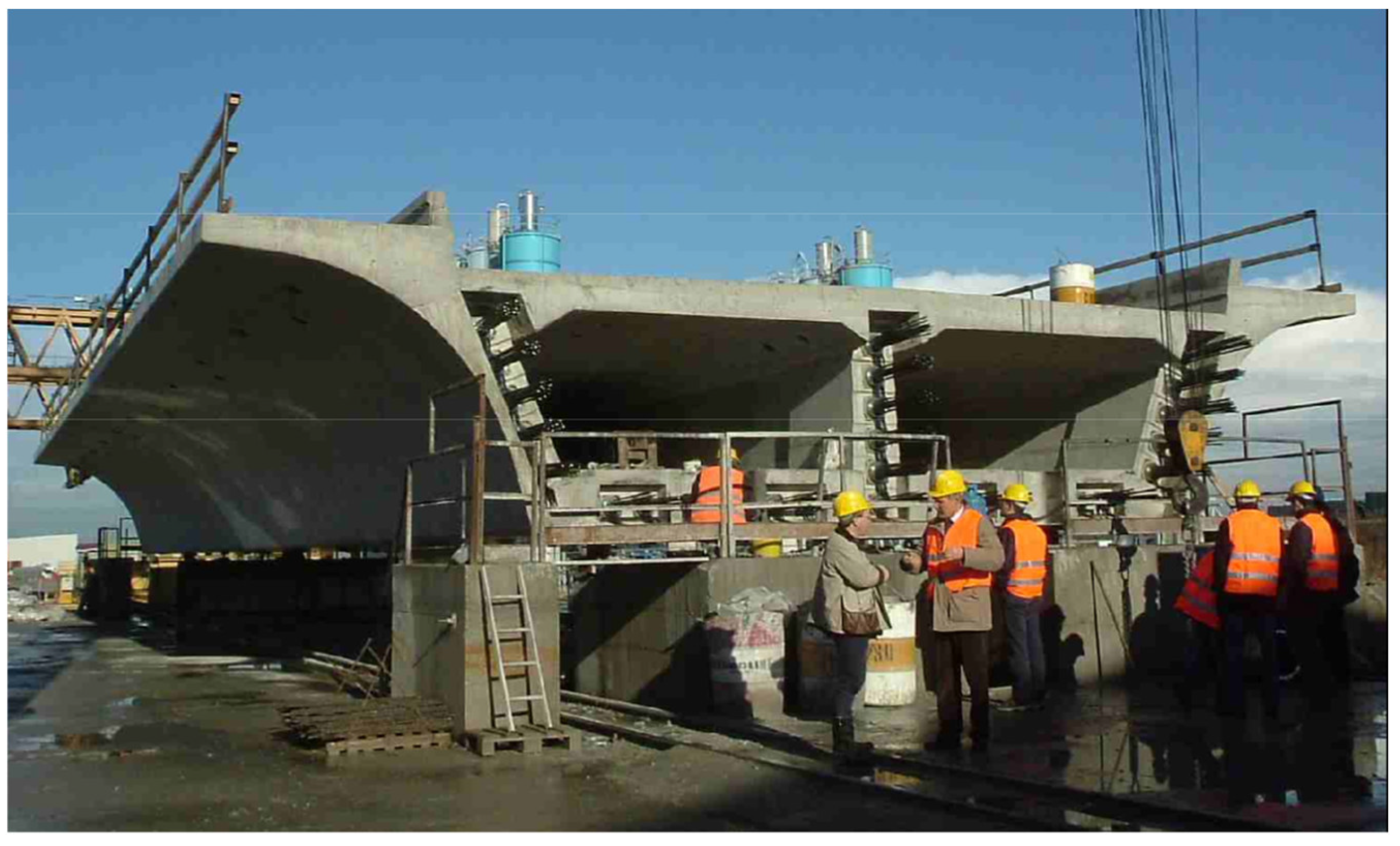
The Piacenza viaduct on the Milano-Bologna line in the Italian high-speed network consists of 151 simply supported full-span pre-cast and prestressed concrete decks composed by a monolithic box girder with two cells. Each segment spans 33.1 m and weighs about 1000 tons (
Figure 4) [
19]. During construction data have been collected from the first 71 decks of the Piacenza viaduct, each containing 9 cables with 12 wires, duct ø 76 mm (in the lower slab) and 15 cables with 19 wires, duct ø 100 mm (in the webs).
Measuring the capacitance C allowed a first control on the execution quality. The values of the capacitance of the tendons ø 76 mm are Gaussian distributed with a mean value of 70.3 nm ± 2.3 nm, the very small standard deviation indicates the good reproducibility in production. The specific capacitance C/m (per meter length) is well below the control values specified in [
14], indicating that the duct wall thicknesses are slightly higher than specified [
20].
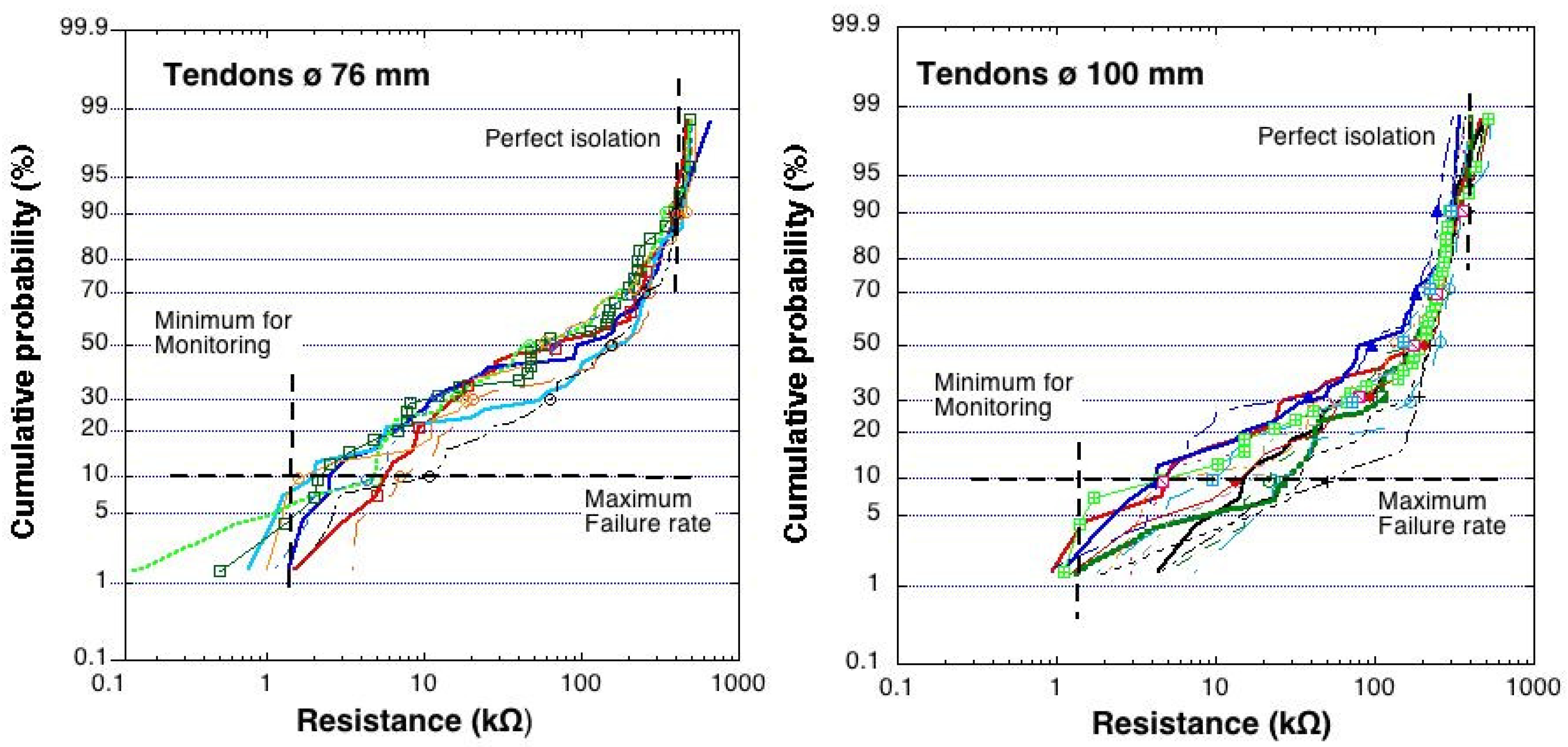
The measured resistance value R of more than 1000 tendons of the Piacenza viaduct—despite the constant length of the tendons—do not show a gaussian distribution. The cumulative probability plot for the tendons with ø 76 mm and ø 100 mm from the segments of the Piacenza viaduct (
Figure 5) show that less than 1% of all values are below 10 Ohm, thus cables with a short circuit (electrical contact between tendon and normal rebars). The limiting value of the specific resistance R
l = 50 kΩm according to [
14] results in a limiting resistance value R = 1.5 kΩ for the tendon with length 33.1 m. This acceptance criteria are not reached by about 8–10% of all the tendons. In addition, it can be noted that for each tendon position about 5% of all full span bridge deck segments were produced with perfect isolation (reaching the theoretical value of a completely tight plastic duct). The broad distribution of resistance values measured shows that there is a strong influence of the human factor, as written procedures, as the approved material and components (deck formwork, reinforcement and pre-stressing) were identical.
4. Long Term Monitoring of Structures
One of the main advantages of EIT systems in post-tensioned tendons is that they can be periodically tested during the whole service life to assess whether the strands in the tendon are still protected from corrosion. In general, the electrical resistance of a tendon inside a concrete structure exposed to the atmosphere increases (similar to the concrete strength) over time due to cement hydration and due to drying out, following a trend line in the log R vs. log t graph (
Figure 6). This increase in resistance has been determined in laboratory experiments [
17], the observed increase can be used to compensate for the time of measurement (often preferable before 28 days) with the formula R
28d = R
t x √28/t as in the Swiss Guideline 2007 [
14].
A decrease in the measured electrical resistance over time clearly indicates that water is penetrating in the duct and has entered the tendon encapsulation at one of the defects (present from the beginning) in the duct (
Figure 6). It is important to note that even tendons that did not meet the required acceptance threshold (except a short circuit occurred) may still be monitored in the long-term for the effect of ingress of water (and mostly chlorides) in the duct. Once a decrease in the resistance of a tendon is detected, the defects in the duct can be located, imposing an AC voltage between the high strength steel and the reinforcement (using the same electrical connections as for the impedance measurements). As a result, an electrical current is flowing through the tendon. Measuring the magnetic field associated with this current with sensors put on the concrete surface, the points where the current is leaving the tendon can be located and the defect can be detected [
17,
18].
5. Conclusions and Outlook
Electrically isolated tendons (EIT) are a proven system to enhance the durability of structures with post-tensioned tendons to the highest protection level PL3. Results from structures in Switzerland and a large-scale application in the Piacenza Viaduct of the high-speed train lines in Italy document the successful application of the EIT in practice.
Measurements of the electrical resistance on electrically isolated tendons have shown to be an efficient way for quality control of the tendons. The acceptance criteria should be considered as a guideline and not enforced strictly. There are instances where readings may not fully meet criteria but may still allow long-term monitoring.
Monitoring over time the electrical resistance of the tendons allows detecting the penetration of (chloride containing) water at defects into the ducts, long before corrosion damage occurs. For the first time, a simple, cost-effective early warning system for post-tensioned tendons is available.
Measurements of the magnetic field associated with an imposed current between tendon and reinforcement allow locating defects (short circuits and holes) in the tendons. For optimum success the tendons should have an electrical connection at both ends.
The use of electrically isolated tendons (EIT) can provide in-service PT tendon durability information and improve the construction/installation quality. In recognizing these benefits EIT technology is becoming implemented more and more in US construction practice [
21,
22].


