Article

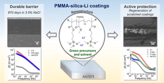
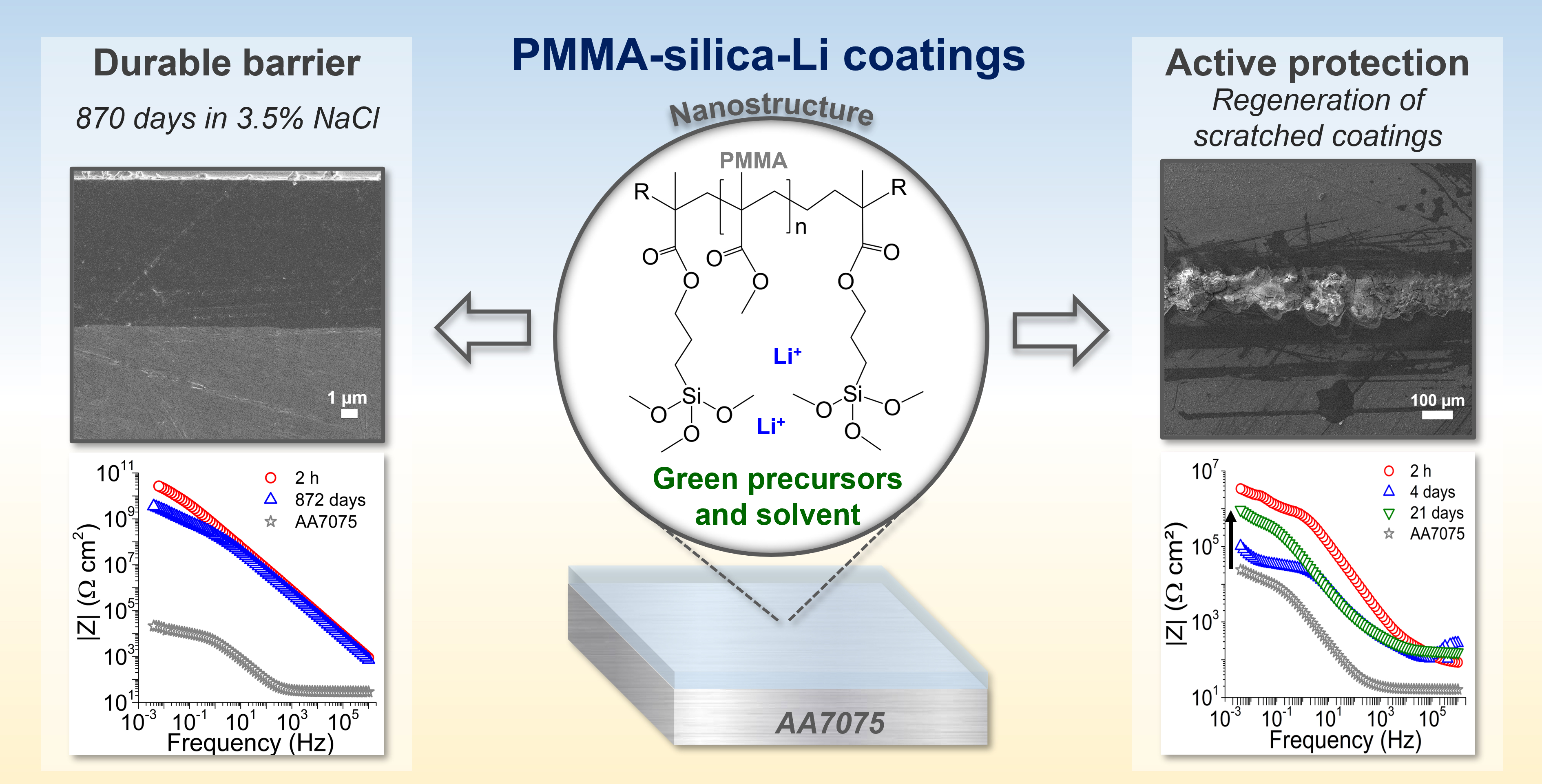
Green-High-Performance PMMA–Silica–Li Barrier Coatings

by
Andressa Trentin
1,2,
Victória Hellen Chagas
1,
Mayara Carla Uvida
1,
Sandra Helena Pulcinelli
1,
Celso Valentim Santilli
1 and
Peter Hammer
1,*
1
Institute of Chemistry, São Paulo State University (UNESP), Araraquara 14800-060, Brazil
2
FunGlass, Alexander Dubček University of Trenčín, Študentská 2, 911 50 Trencin, Slovakia
*
Author to whom correspondence should be addressed.
Corros. Mater. Degrad. 2022, 3(3), 303-319; https://doi.org/10.3390/cmd3030018
Submission received: 27 May 2022 / Revised: 21 June 2022 / Accepted: 22 June 2022 / Published: 24 June 2022
(This article belongs to the Special Issue Corrosion Barrier Coatings)

Abstract

:
Organic-inorganic coatings based on polymethyl methacrylate (PMMA)–silica–lithium are an efficient alternative to protect metals against corrosion. Although the preparation methodology is established and the thin coatings (~10 µm) are highly protective, the use of an environmentally friendly solvent has not yet been addressed. In this work, PMMA–silica coatings were synthesized using 2-propanol as a solvent and deposited on aluminum alloy AA7075, widely used in the aeronautical industry. Different concentrations of lithium carbonate (0–4000 ppm) were incorporated into the hybrid matrix to study the structural and inhibitive effects of Li+ in terms of barrier efficiency of the coatings in contact with saline solution (3.5% NaCl). Structural and morphological characterization by low-angle X-ray scattering, X-ray photoelectron spectroscopy, atomic force microscopy, thermogravimetric analysis, thickness, and adhesion measurements, showed for intermediate lithium content (500–2000 ppm) the formation of a highly polymerized PMMA phase covalently cross-linked by silica nodes, which provide strong adhesion to the aluminum substrate (15 MPa). Electrochemical impedance spectroscopy (EIS) results revealed an excellent barrier property in the GΩ cm2 range and durability of more than two years in a 3.5% NaCl solution. This performance can be attributed to the formation of a highly reticulated phase in the presence of Li, which hinders the permeation of water and ions. Additionally, the self-healing ability of scratched samples was evidenced by EIS assays showing a fast Li-induced formation of insoluble products in damaged areas; thus, constituting an excellent eco-friendly solution for corrosion protection of aerospace components.

Graphical Abstract

1. Introduction

Metals such as iron, copper, aluminum, titanium, magnesium, and their alloys constitute a significant portion of materials produced and applied today in the maritime, aeronautical, automobile, and infrastructure sectors. However, over the years and under aggressive conditions, these materials undergo metallic corrosion, converting them to their original ore. Corrosion-induced damage represents one of the main problems related to public safety, failure of critical components, and environmental impacts, leading to exorbitant expenses for maintenance and replacement [1]. It is estimated that the annual costs of corrosion are equivalent to 3.4% of the global Gross Domestic Product [2].
Considering this scenario, several strategies have been developed to mitigate the impacts associated with metallic corrosion, including the use of new metallic alloys with greater strength and corrosion resistance, conversion layers (anodizing, phosphating, chromating), and the application of protective coatings. However, all these strategies suffer from drawbacks such as high costs of novel alloys, toxicity of the hexavalent chromium conversion process, poor mechanical stability of anodic layers, low thermal stability and poor adhesion to metallic substrates of organic paints, and residual porosity combined with stress-induced cracking of inorganic coatings [3,4,5,6]. Among protective coatings designed to provide a physical barrier against corrosive species, the most common is a 50–150-µm-thick organic multilayer system which, after surface treatment and phosphating/anodization, consists of a primer containing pigments and corrosion inhibitors and polymeric topcoats [7].
Nowadays, the major challenges in producing efficient barrier coatings are: (i) selection of environmental compliant systems that provide an effective anticorrosive barrier at low material costs; (ii) utilization of simple, green, and economic preparation methods; (iii) compatibility of inhibiting additives with the barrier material preserving its integrity; (iv) strong adhesion of the coating material to the metallic surface; and (v) establishment of reproducible performance during extended exposure times. In the past decades, significant advances have been achieved to meet most of these requirements, although the latter criterion remains the most challenging.
The most promising candidates for high-performance anticorrosive barriers are organic-inorganic nanocomposites in the form of a few micrometer thick layers, which synergically combine the processability, flexibility, and hydrophobicity of polymers with high mechanical, thermal and chemical stability of ceramic materials such as silica, which also provide strong adhesion to metallic substrates [4]. Using inexpensive molecular and ionic agents, the combination of the sol-gel route with the polymerization process opens the possibility to prepare at mild conditions thin (<10 µm), adherent, and highly reticulated hybrid nanocomposites, which act as a high-performance barrier with long-term stability [8]. These characteristics make the modified acrylic–silica and epoxy–silica hybrids the materials of choice for future high-efficiency anticorrosive coatings on all types of metallic components [8,9]. In these amorphous systems, the silica nodes act as crosslinking agents by contracting polymeric segments and providing strong adhesion to the metallic substrate, while the polymeric matrix hermetically seals the structure, acting as an effective barrier against corrosive species [9,10,11]. The covalent conjugation between both phases is provided by a coupling agent consisting of a siloxane group linked to a methacrylate or epoxy tail [10].
The aluminum alloys of the 7000 series, which are mainly used in the aeronautical industry for their high mechanical resistance, suffer from high susceptibility to corrosion, which represents a major obstacle in terms of durability and safety of the components based on this alloy. The corrosion process occurs preferentially at intermetallic copper and zinc sites with cathodic character [12]. Therefore, the development of effective corrosion protection by a durable barrier coating containing an appropriate cathodic inhibitor is of high priority [7,9].
A number of recent studies have investigated the effects of the inclusion of different corrosion inhibitors in hybrid coatings based on cerium, lithium, and molybdenum salts and organic inhibitors, such as 2-mercaptobenzimidazole, that are capable of significantly prolonging the service life of metallic components by retarding the progression of corrosion and the self-healing ability [7,13,14,15,16,17]. In the event of corrosive or mechanical damage, ionic species are released from the bulk into corrosion-affected zones and act as a cathodic inhibitor by reacting with hydroxyls from the oxygen reduction reaction, forming an insoluble layer that prevents the progress of corrosive action [13,14,18]. Despite the high performance of these coating systems, most formulations used for the preparation involve harmful solvents, making their use on the industrial scale problematic.
Focusing on the second and fifth key factors mentioned previously concerning an environmentally compliant formulation and allowing up-scalable fabrication of reproducible high-performance barrier, this work aimed to prepare high-performance poly(methyl methacrylate) (PMMA)–silica coatings using green, low-cost reagents, which provide efficient and reliable protection for the aluminum alloy AA7075. For that purpose, a Li-based inhibitor in the form of lithium carbonate was added to the coatings at different loadings to assess the structural, thermal, surface, and electrochemical properties before and after long-term exposure to standard saline solution.

2. Materials and Methods

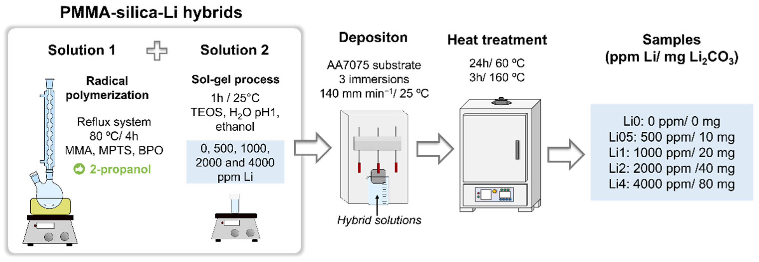
2.1. Synthesis of PMMA–Silica–Li Hybrids

PMMA–silica–Li hybrids were obtained by mixing two solutions prepared separately. The reagents were used as commercially available, except for the methyl methacrylate (MMA, Sigma Aldrich, St. Louis, MO, USA) monomer, which was distilled to remove the hydroquinone inhibitor. In the first solution, the polymerization of the MMA monomer and functionalization with 3-methacryloxypropyl trimethoxysilane (MPTS, Sigma Aldrich) was carried out in the presence of the initiator benzoyl peroxide (BPO, Sigma Aldrich) using 2−propanol (Synth) as a solvent, for 4 h at 80 °C in a reflux system under constant stirring. In parallel, the silica nanophase was obtained by the sol-gel route through hydrolysis and condensation reactions of tetraethyl orthosilicate (TEOS, Sigma Aldrich) in acidified aqueous solution (pH 1, HNO3 (Sigma Aldrich)) using ethanol (Synth) as solvent, under constant stirring at 25 °C for 1 h. Lithium carbonate (Li2CO3, Sigma Aldrich) was added to the second solution in the concentration range of 0−4000 ppm, and the control of the pH of 1 in the presence of Li2CO3 was accomplished by the addition of HNO3. Finally, both solutions were mixed and homogenized for 1 min. The molar ratios between the synthesis precursor reagents and the volumes used were MMA/TEOS = 4 (7.830 mL/4.080 mL); BPO/MMA = 0.05 (0.886 g/7.830 mL); TEOS/MPTS = 2 (4.080 mL/2.175 mL); ethanol/H2O = 0.5 (2.835 mL/1.730 mL) and H2O/Si = 3.5. The PMMA–silica–Li hybrid samples were named according to the amount of Li2CO3 added: Li0 (reference); Li05 (500 ppm, 10 mg), Li1 (1000 ppm, 20 mg), Li2 (2000 ppm, 40 mg), and Li4 (4000 ppm, 80 mg).

2.2. Deposition of the Coatings

The substrates (25 × 25 × 2 mm) were obtained by cutting a bar of the aluminum alloy AA7075-T3 (GGD Metals) with nominal composition (wt%) of 0.3 Mn, 0.09 Si, 0.24 Cr, 0.05 Ni, 1.48 Cu, 2.6 Mg, 0.37 Fe, 5.64 Zn, and 0.2 Ti and Al balance.
The deposition of the coatings was performed by immersion in the final hybrid solutions using a commercial dip-coater (Microtube), with an immersion/emersion rate of 140 mm min−1 and 3 immersions of 1 min and air-drying intervals of 10 min. Before deposition, the substrates were polished using 600 and 1500 grit SiC abrasive sandpaper (Arotec), then immersed in 2-propanol for cleaning in an ultrasonic bath for 10 min and dried under dry nitrogen flow.
After deposition, the remaining hybrid solution was distributed equally in Teflon cups to obtain freestanding films and then all samples were submitted to a heat treatment for 24 h at 60 °C and 3 h at 160 °C, to eliminate solvents and complete polymerization/condensation of the hybrids. The representation of the experimental procedure is shown in Figure 1.

2.3. Characterization

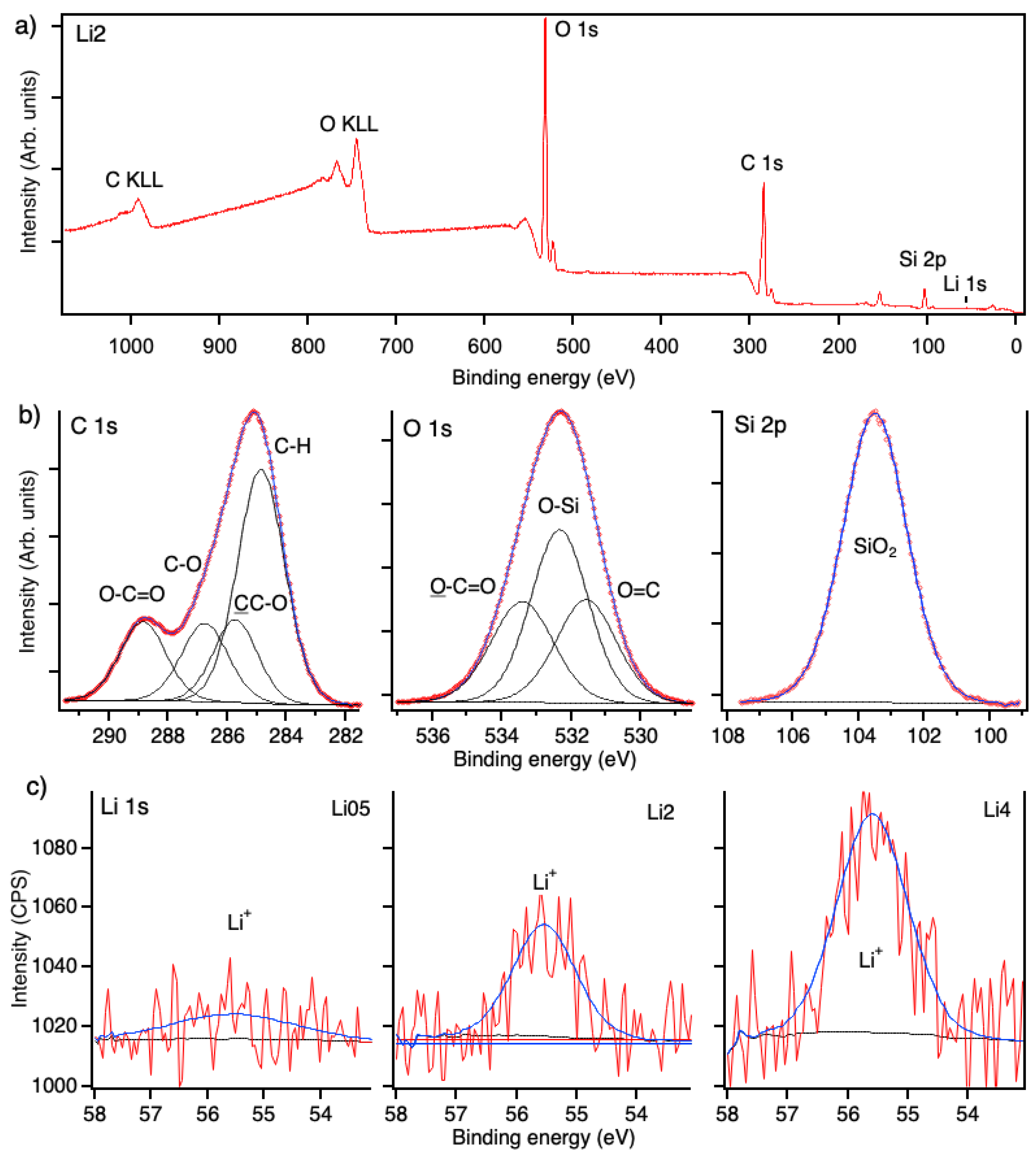
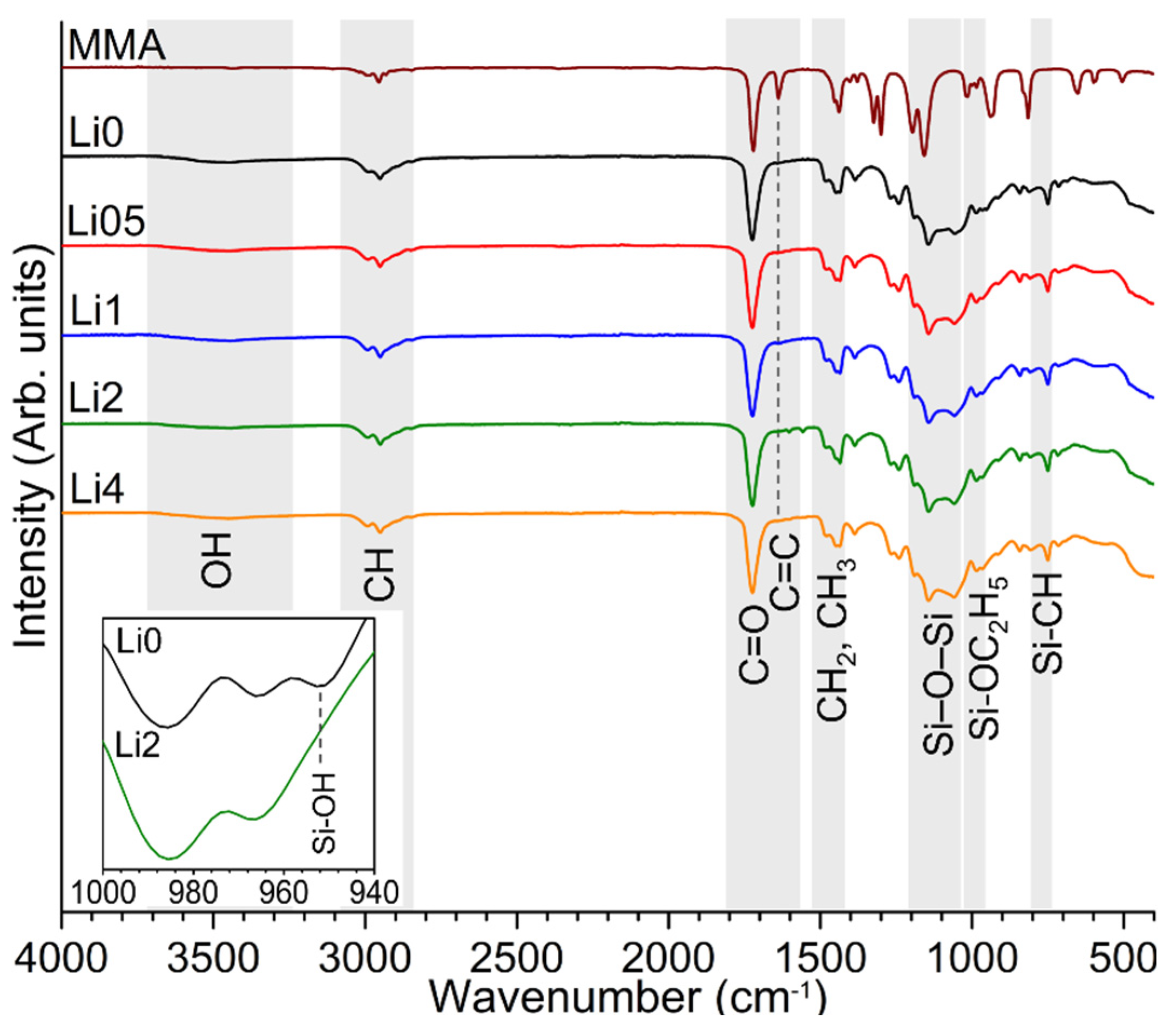
2.3.1. Chemical and Structural Analysis

Structural characterization for the PMMA–silica–Li hybrids with different concentrations of lithium was performed by Fourier transform infrared spectroscopy in attenuated total reflection mode (ATR-FTIR) using a Vertex 70 spectrometer (Bruker, Billerica, MA, USA). The spectra were recorded in the range from 4000 to 400 cm−1 with a resolution of 4 cm−1 and 64 scans.
The nanostructural characteristics of the freestanding hybrids were investigated by small-angle X-ray scattering (SAXS) using a Nano-In Xider instrument (Xenocs, Grenoble, France) equipment with Cu Kα monochromatic radiation and a Dectris Pilatus 3 detector, located at a 938 mm distance from the sample. The scattering intensity I(q) is a function of the scattering angle θ and the scattering vector, expressed by q = ( 4 π / λ )   s i n ( θ / 2 ) . The scattering in the hybrids occurs due to a difference in electron density of the silica nanodomains relative to the polymer matrix. The position of the maximum of the correlation peak (qmáx) was used to determine the average distance between the silica nanodomains using the equation d = 2 π / q m á x .
X-ray photoelectron spectroscopy (XPS) analysis was performed in a UNI-SPECS UHV Surface Analysis System using an Mg Kα (1254.6 eV) source for photoelectron excitation and an analyzer pass energy of 15 eV to obtain high-resolution spectra. The elemental composition and chemical bonding structure of intact and scratched coatings before and after corrosion tests was carried out from the analysis of the carbon (C 1s), oxygen (O 1s), silicon (Si 2p), and Li 1s spectra. The weak Li 1s intensities were recorded as an average of 15 scans using a 5 channeltron detector system and the default function for background subtraction (CasaXPS). The binding energy scale was corrected using the C 1s component of the PMMA ester group (O-C=O) at 288.9 eV, and the surface layer composition was determined after corrections of the intensities using the Scofield atomic sensitivity factors of the corresponding elements. The high-resolution spectra were deconvoluted using the CasaXPS software applying Voigt functions with a full width at half maximum (FWHM) between 1.2 and 2.2 eV.

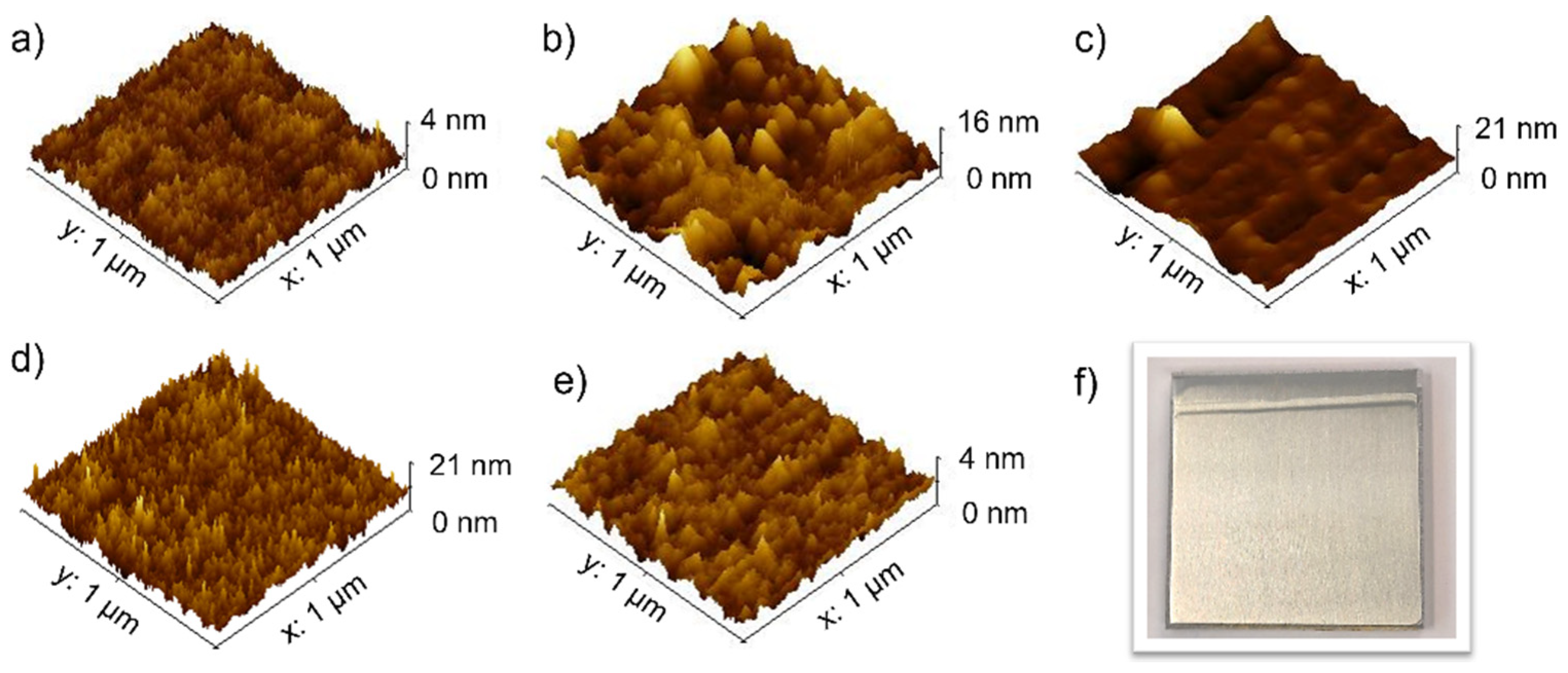
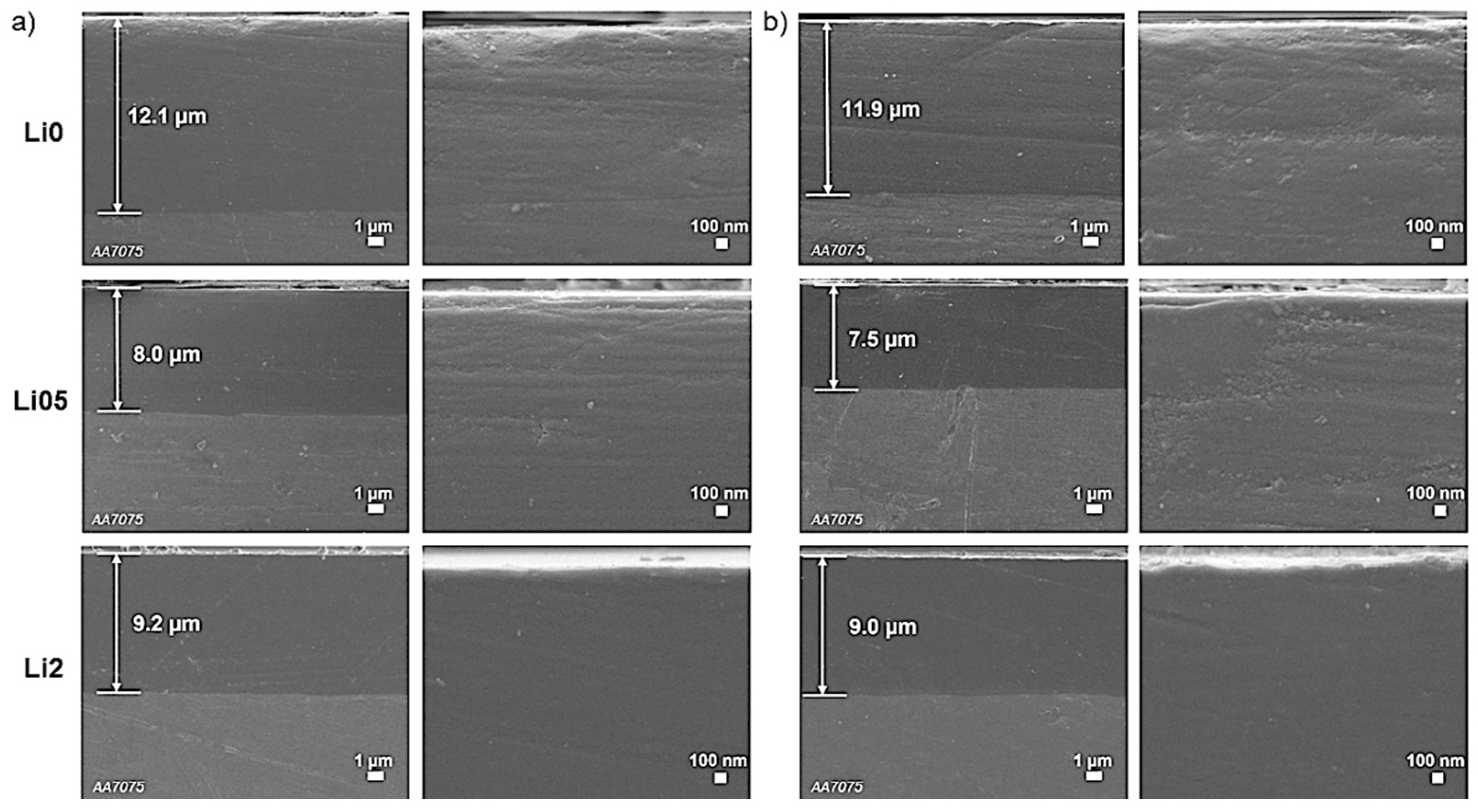
2.3.2. Adhesion, Thickness, and Morphology of Coatings

The coating adhesion to the substrate was evaluated using an Elcometer 510 Automatic Pull-Off Adhesion Gauge. Before testing, the coating surface was lightly scratched with SiC sandpaper (grit 600), cleaned with 2-propanol for fixation of the aluminum dolly (Ø 10 mm) perpendicularly using Araldite® 2000+ glue, and then oven-cured for 3 h at 100 °C. After 24 h, the pin was fixed to the instrument gauge, and a tensile force at a rate of 0.8 MPa s−1 was applied to determine the critical force (MPa) of coating removal. The adhesion strength obtained for each sample refers to the average of 2 measurements.
The surface morphology of the coatings was evaluated in an area of 1 μm2 using an atomic force microscope (AFM–Agilent 5500 series) equipped with a silicon cantilever in tapping acquisition mode. To determine the RMS (root means square) roughness of the coatings, the Gwyddion software was used. The thickness of the coatings was determined using an optical interference system (Filmetrics F3-CS).
The cross-section of the coatings before and after long-term exposure to the saline solutions was analyzed by JSM-7500F field emission gun scanning electron microscopy (FEG-SEM–JEOL) coupled with energy-dispersive X-ray spectroscopy (EDS, Thermo Scientific Ultra Dry), using 2 kV of accelerating voltage and 6.0 mm of working distance. For the cross-section analyses, the coated substrates were cut, embedded in resin, and polished using 600 grit SiC sandpaper, 1 and 0.3 µm alumina oxide suspension, respectively. Prior to analysis, a carbon layer was evaporated to avoid charging effects.

2.3.3. Thermal Analysis

The thermal stability of the hybrids was assessed using thermogravimetric analysis (TGA) for freestanding films using an SDT Q600 equipment (TA Instruments, New Castle, DE, USA) with a sample mass of about 7 mg in an alumina crucible, a continuous nitrogen flow of 100 mL min−1, a heating rate of 5 °C min−1, and a temperature range between 25 and 800 °C.

2.3.4. Electrochemical Measurements

The corrosion performance of the coatings and the uncoated AA7075 alloy was evaluated in a neutral saline environment (3.5% NaCl solution) by electrochemical impedance spectroscopy (EIS) using a Gamry Reference 600 Potentiostat. A three-electrode electrochemical cell was used for the tests: the coated/uncoated aluminum substrate as the working electrode, a platinum counter electrode, and an Ag|AgCl|KClsat reference electrode. A platinum wire was connected to the reference electrode by a 0.1 µF capacitor to avoid phase shifts at high frequencies. After stabilization of the open circuit potential (OCP), a 10 mVRMS sinusoidal potential was applied, and the frequency was varied between 1 MHz and 5 mHz, with 10 points per decade. To evaluate the self-healing ability, the coatings on AA7075 were artificially damaged using a pen-type scriber with a tungsten carbide tip, resulting in scratches with a length of 50 mm and a width of about 50 µm. The scratched coatings were continuously immersed in a 3.5% NaCl solution for 21 days and the corrosion inhibition properties of lithium ions were evaluated by EIS assays. The impedance plots were fitted with Zview® (Scribner Associates, Southern Pines, NC, USA), using electrical equivalent circuits discussed below.
To guarantee high precision and reproducibility of the results, all measurements, except for XPS, were performed in duplicate.

3. Results and Discussion

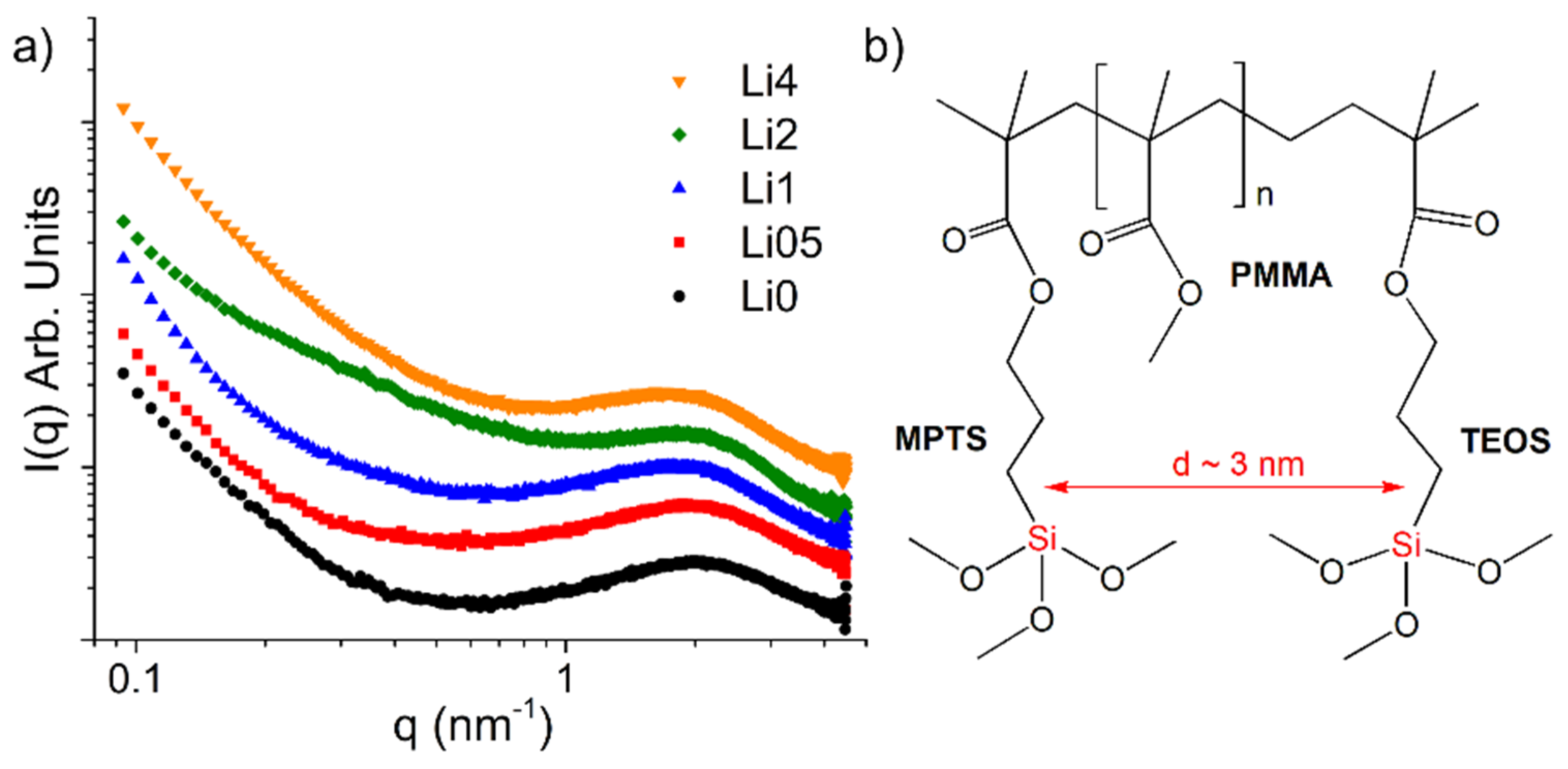
3.1. Structural Properties

X-ray photoelectron spectroscopy (XPS) was employed to study the bonding structure and composition of the PMMA–silica coatings with increasing Li loading. The quantitative XPS analysis confirmed the formation of the hybrid, as well as the presence of lithium, as shown in Figure 2a for the Li2 sample. The organic to inorganic phase ratio is in agreement with the nominal proportions of polymerized and hydrolyzed MMA:MPTS:TEOS precursors of 8:1:2, corresponding to 59.6 at.% carbon, 34.0 at.% oxygen, and 6.4 at.% oxygen. The lithium content varied between ~0.2 at.% (Li05), 0.6 at.% (Li2), and 0.9 at.% (Li4).
The deconvolution of the normalized C 1s, O 1s, and Si 2p spectra allowed verifying the presence of the functional groups of the hybrid (Figure 2b). The components fitted for C 1s correspond to the four chemical environments of carbon:hydrocarbon groups (CHx) at 284.9 eV, the second neighbor of the carbon atom attached to the ester group (CC-O) at 285.6 eV, the ether group (C-O) at 286.7 eV, and the ester group (O-C=O) at 288.9 eV. The latter three sub-peaks were of equal intensity as they represent a single bonding environment in the MMA/MPTS structure. The O 1s spectrum, on the other hand, shows three bonding environments of oxygen: the main component at about 532.8 eV is related to O-Si bonds, the subpeak located at 531.6 eV refers to the oxygen double bond (O=C), and that at 533.5 eV to the oxygen single bond (O-C=O), both of the ester group. The Si 2p peak shows an interesting feature with the presence of only a single component referring to SiO2 at 103.4 eV, indicating high connectivity of the silica phase. This is supported by results of 29Si nuclear magnetic resonance and XPS, reported for PMMA–siloxane–silica hybrid coatings presenting a degree of polycondensation of up to 90% [8,10]. The single component at 55.4 eV of the Li 1s spectra was attributed to the presence of intercalated Li ions (Figure 2c) [19].
To get a better insight into the formed nanostructure, SAXS experiments were carried out (Figure 3a and Figure S1). The scattering profiles present an increasing intensity toward lower q-values (larger scatterers) and a broad peak in the higher q-range, which is associated with the scattering of the silica phase. The appearance of this so-called correlation peak indicates the presence of a concentrated set of nanometric silica domains that are almost equally spaced in the PMMA matrix. As shown in the structural representation of Figure 3, the uniform and concentrated dispersion of these silica nodes can be attributed to the effect of the MPTS coupling agent that conjugates covalently the silica phase with PMMA segments; thus, forming a dense cross-linked organic-inorganic network. The peak position (qmax) allows determining the average correlation distance between the silica domains using d = 2π/qmax (Table 1) [10,16]. The average distance increased slightly with Li addition from 3.0 to 3.7 nm. This increase in d may be related to a higher rate of hydrolysis and condensation induced by lithium carbonate. From the obtained scattering profiles, Li2 stands out due to the smallest width of the correlation peak and smaller slope at lower q-values. This indicates the presence of a more homogeneous nanostructure with evenly distributed silica domains. Figure 3b illustrates the molecular structure formed from MMA, MPTS, and TEOS precursors, with the silica domains separated by approximately 3 nm. The analysis of the second set of samples revealed very similar scattering profiles for all coatings (Figure S1) and in particular for Li2, showing the same tendency of increasing distance with higher Li content.
All prepared coatings have thicknesses between 7 and 12 μm and exhibited an adhesion strength between 6.8 and 15.5 MPa to the AA7075 substrate, with the highest values determined for the Li2 coating (Table 1). The high adhesion is indicative of the presence of covalent bonds between the silanol groups of the hybrid and the hydroxyls of the aluminum oxide layer. In the case of the Li2 coating, the higher values might be related to a more uniform distribution of silica nanodomains (as suggested by SAXS results) that contributes to improved connectivity between the hybrid and the aluminum oxide [20]. Topographic images obtained by atomic force microscopy (AFM), recorded by scanning an area of 1 μm2 (Figure 4 and Figure S2), showed that lithium salt addition leads to an increase in the surface roughness, indicating the presence of larger heterogeneities on the hybrid surface (Table 1). Nevertheless, Li2 coatings presented values of less than 1 nm, indicating a beneficial role of Li in this concentration range. Figure 4f displays a representative image of the Li2 coating on AA7075, showing a homogeneous layer obtained by dip-coating. Samples containing low Li concentrations are transparent and colorless, as reported in [14], while for higher lithium concentrations, a slightly yellowish layer was formed.
The structure of PMMA–silica–Li hybrids was evaluated by FTIR spectra for the freestanding films modified with lithium carbonate in the concentration range of 0–4000 ppm. The characteristic vibrational bands of the inorganic phase identified in Figure 5 at 757 cm−1 are the stretching vibrations of the Si-CH bonds of MPTS [21], at 983 cm−1 the asymmetric stretching vibrations of Si-OC2H5 groups of the non-hydrolyzed TEOS, and the bands at 1055 and 1141 cm−1 associated with the asymmetric stretching vibrations of Si-O-Si bonds [22]. Only for the Li0 sample a low-intensity band at 950 cm−1 was observed (inset of Figure 5), associated with stretching vibrations of the Si-OH bonds of residual non-condensed silanol groups of TEOS and MPTS, indicating an improved degree of polycondensation upon Li addition. The weak absorption band in the range between 3200 and 3700 cm−1 is characteristic for the axial O-H deformation associated with residual non-condensed silanol groups (Si-OH) [22] and possibly also remaining solvent (C2H5OH and H2O) from the synthesis process.
The polymerization of the organic phase was confirmed by the disappearance of the stretching band at 1637 cm−1 of the vinyl group (C=C) of MMA and the presence of absorption bands of functional groups of the molecular structure of MMA and MPTS, such as the C=O stretching vibrations of ester at 1724 cm−1, bending vibrations of the CH2 and CH3 groups at 1386 and 1434 cm−1, and the bands associated with the symmetric and asymmetric stretching of CH2 and CH3 in the region of 2900 cm−1.

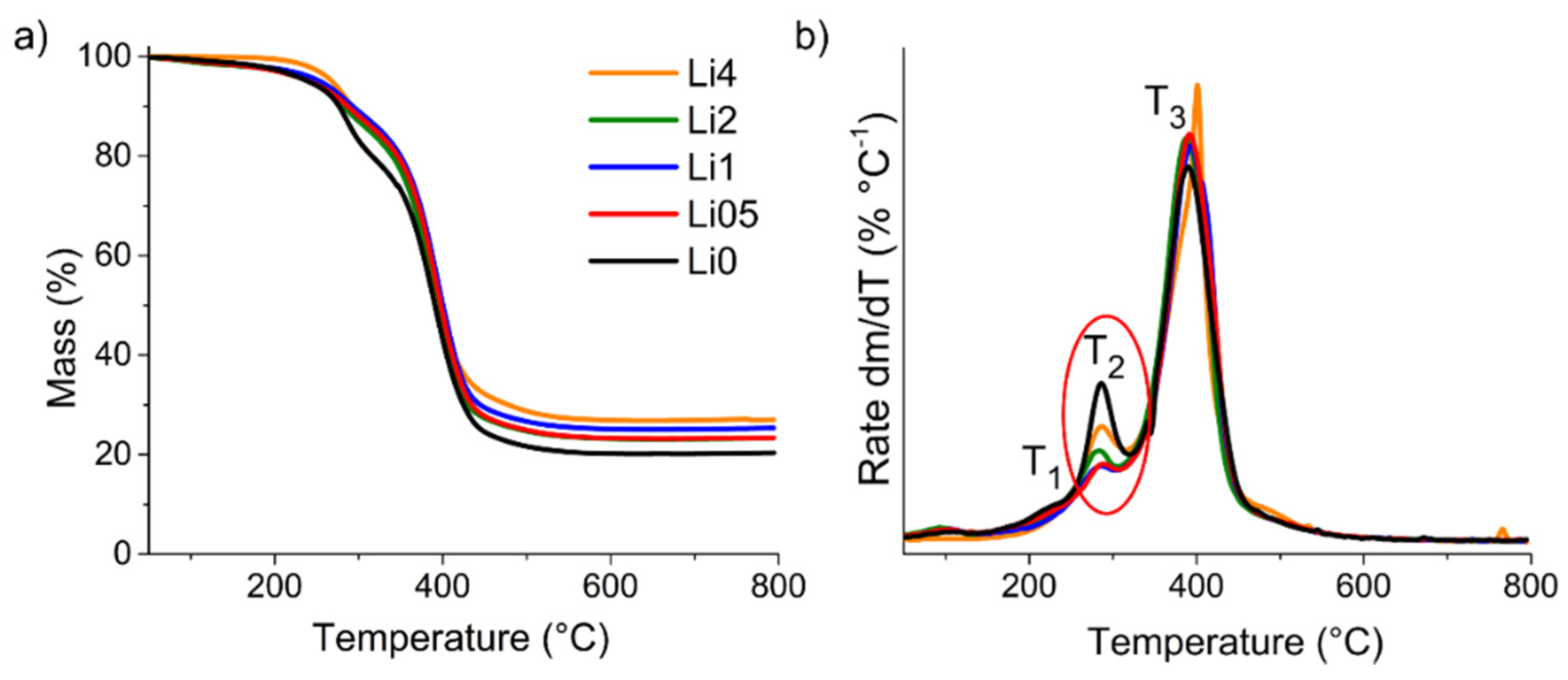
3.2. Thermal Stability

Thermogravimetric analysis (TGA) under a nitrogen atmosphere was used to investigate the thermal stability of freestanding coatings, decomposition events, and the residual mass at 800 °C (Figure 6) [10]. The derivatives of TGA curves (dTG) provide information on the temperatures and rates of formed degradation products and, consequently, on the connectivity of the hybrid network. Figure 6b shows three degradation events with increasing temperature associated with the depolymerization of defective PMMA head-to-head segments (T1 = 220 °C); depolymerization of unsaturated ends (T2 = 280 °C); and complete degradation of the polymer (T3 = 390 °C) [23].
The results show that the addition of lithium carbonate does not impair the polymeric structure, on the contrary, the modified samples present higher thermal stability at 5% mass loss, with values of up to 268 °C (Li4). The residue at 800 °C, formed by silica and to a lower extent of coke, varies between 20% and 27%, which scales with the addition of lithium carbonate (Table 1). Furthermore, the use of 2-propanol solvent leads to a suppression of polymerization defects (T1) compared to PMMA–silica coatings prepared with other solvents as reported elsewhere [4,24]. Additionally, the clear reduction of the T2 event, related to the unsaturated PMMA chain ends, confirms the beneficial role of intermediate loadings of lithium in the MMA polymerization process. Similar behavior was observed for the duplicates (Figure S3), confirming a structural improvement in the hybrid phase in the 500–2000 ppm Li range. Higher Li concentrations (Li4) seem to not have a beneficial effect on the structure, and, therefore, inferior barrier properties can be expected.

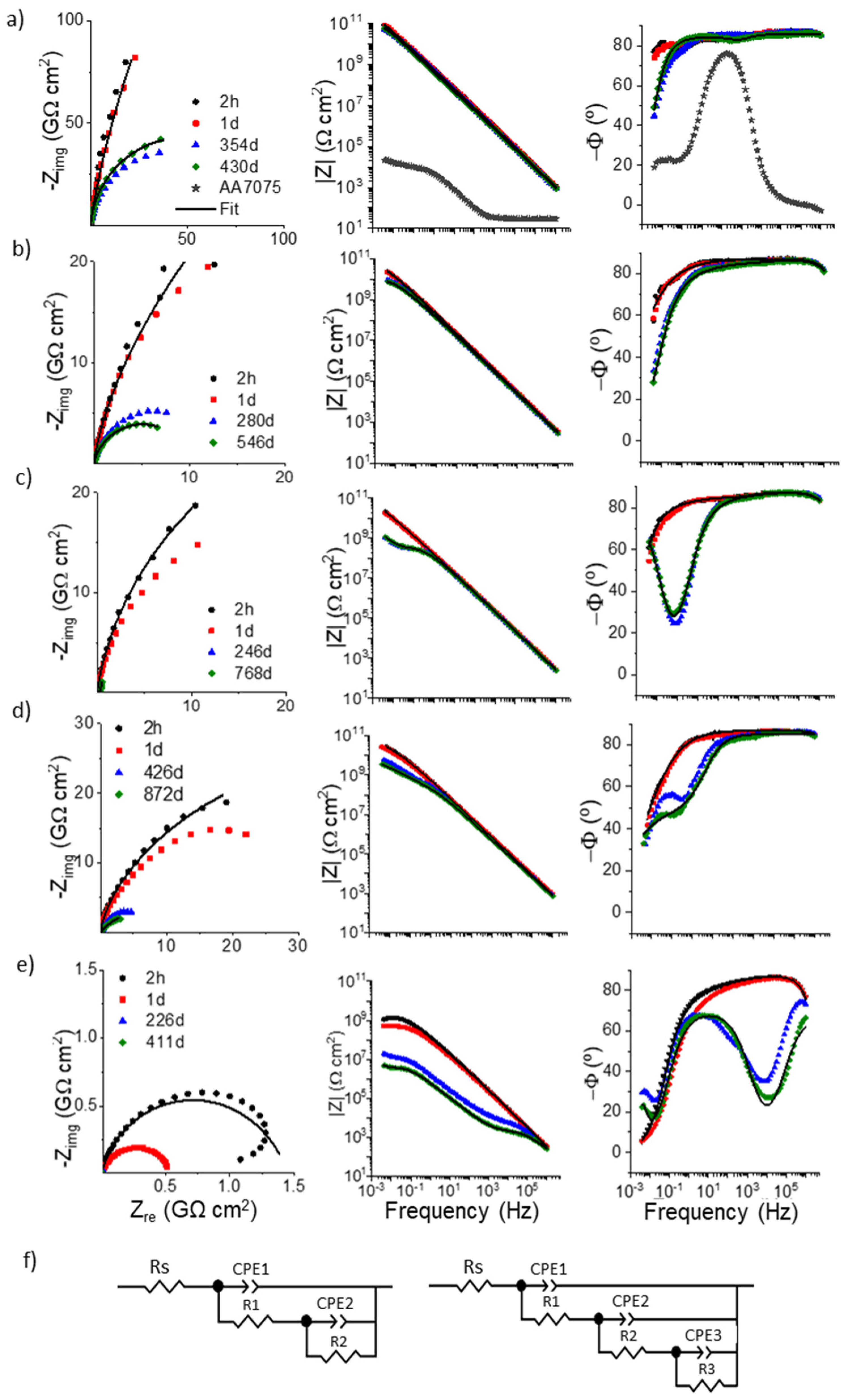
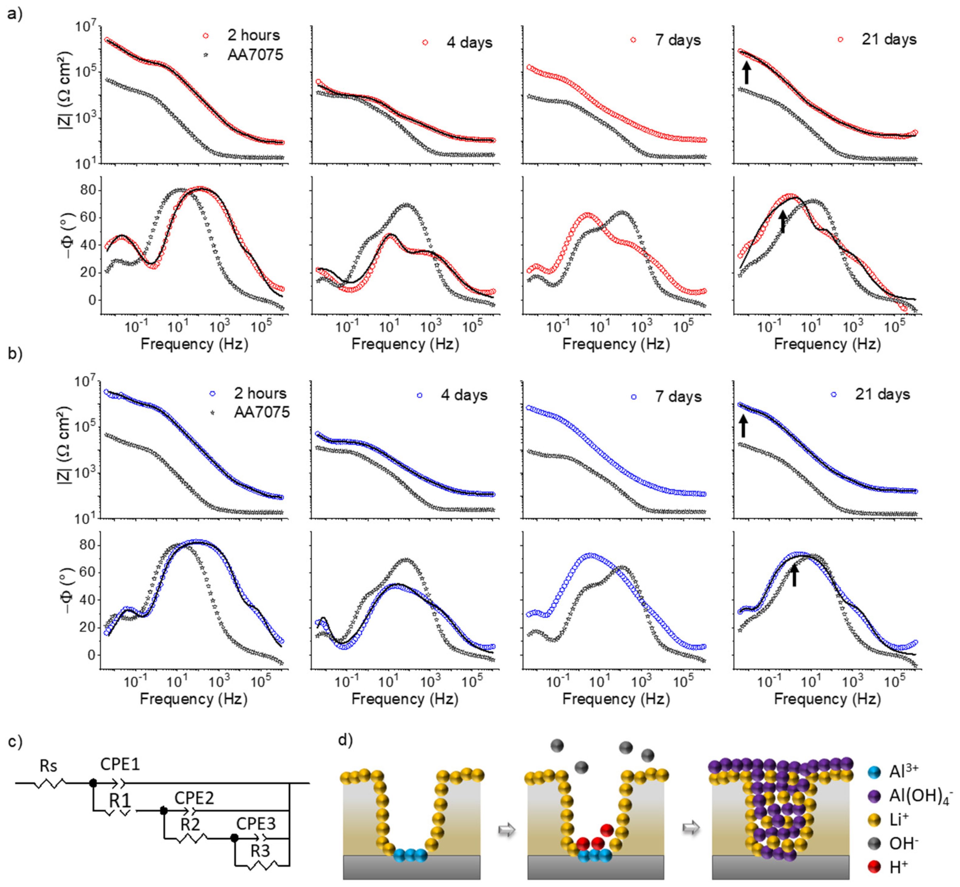
3.3. Electrochemical Barrier Properties

To evaluate the barrier properties in terms of durability in 3.5% NaCl solution, duplicate PMMA–silica–Li coatings on the AA7075 alloy were studied at weekly intervals by electrochemical impedance spectroscopy (EIS). The obtained Bode plots for the frequency dependence of the impedance modulus and phase angle provide important information on the anticorrosive performance of the coatings, since high modulus values and capacitive phase angle values close to −90° are characteristic of a barrier that is approaching the behavior of ideal capacitor, inhibiting the transfer of corrosive species to the metal/coating interface.
The time-dependent Nyquist and Bode profiles, shown in Figure 7, reveal that in the first days of immersion, all coatings exhibit high corrosion resistance with a low-frequency impedance modulus up to six orders of magnitude higher than bare aluminum and a quasi-ideal capacitive behavior of the phase angle over a wide frequency range. For exposure times of more than one year for all samples, except for Li4, the coatings show excellent barrier properties, highlighting the long-term stability of the Li2 sample maintaining a high impedance in aggressive solution over more than two years without failure (Figure 7d). This performance, confirmed in Figure S4 for the second set of samples, is comparable to the best anti-corrosion coatings reported to date [4,14,23]. The coating with the highest lithium concentration (4000 ppm) showed an initial impedance modulus of about one order of magnitude lower and then a continuous decrease over longer exposure periods, suggesting that the integrity of the hybrid network was impaired by Li2O3 incorporation. This is reflected by a sharp drop in the phase angle in the high-frequency range, indicating the formation of percolation paths toward the metal/coating interface [8].
The EIS data of the first and last measurements were fitted using electrical equivalent circuits (EEC) presented in Figure 7f. They are composed of a solution resistance (Rs) in series with RC elements related to two (Li0–Li2) and three (Li4) time constants. Generally, the first and the second time constants (CPE1/R1 and CPE2/R2) are attributed to the resistance and the capacitance in the form of constant phase element (CPE), to the coating and the passive layer, respectively. The third time constant (Rct/CPEdl) is related to the charge transfer resistance and double-layer capacitance.
The time evolution of the obtained electrochemical parameters (Table S1) shows that a lithium content of up to 2000 ppm has a beneficial effect on the electrochemical barrier properties of the coatings. This can be explained by a less defective polymer structure found by TGA and uniform distribution of highly polycondensed silica nanodomains in the PMMA matrix, evidenced by SAXS and XPS. A possible mechanism to explain the beneficial structural effect of lithium ions is supported by the network modifier activity reported for these ions. It has been shown that lithium ions form complexes with MMA monomers; thus, favoring the chain growth [25], and driving higher condensation kinetics of free silanols by providing a charge balance [26]. Concerning the performance drop at higher Li+ concentrations (4000 ppm), a recent study reported a similar finding showing that concentrations > 3000 ppm of Ce(IV) ions impair the structural homogeneity of PMMA–silica coatings [23], indicating a threshold for the incorporation of additives in this system. This is possibly due to the presence of non-dispersed salt after reaching the limit of solubility.
The coating morphology was evaluated by cross-sectional SEM images before (Figure 8a) and after exposure in 3.5% NaCl solution for the Li0, Li05, and Li2 coated samples (Figure 8b). The micrographs show that the coatings with thicknesses between 7.5 and 12.1 µm are homogeneous, compact, free of pores and defects, and remain essentially unchanged after long-term immersion (Li0, 817 days; Li05: 546 days; and Li2, 872 days). The thickness values are in good agreement with those obtained by optical interferometry. Details at the upper part of the coating cross-section for intact and exposed coatings (Figure 8a,b), exhibit no significant changes for the Li2 coating. For Li0 and Li05, a slightly porous microstructure in a zone of about 2 µm can be observed as a consequence of electrolyte permeation and polymer swelling. Nonetheless, the bulk and the coating/substrate interfaces remained unaffected with no visible signs of permeation. This is in agreement with the excellent long-term stability of the coatings found by EIS, indicating a very slow progression of uptake toward the AA7075 coating/alloy interface.
Electrochemical, thermal, barrier, and mechanical properties of PMMA–silica coatings reported so far are compared with those found in the present work in Table 2. Excellent barrier properties have been reported for PMMA–silica and acrylic–silica coatings synthesized at similar conditions even when tested under harsh conditions such as acidic [9] and alkaline [14] solutions. Nonetheless, despite their high performance, most formulations use toxic solvents such as tetrahydrofuran, butyl acetate, and xylene. This data compilation highlights the relevance of the results obtained in this study, since no comparable outcomes have been reported for green solvents, proving the potentiality of this system as a promising alternative for anti-corrosion applications in aggressive environments.
The active corrosion protection of the PMMA–silica coatings with lithium ions acting as a self-healing agent was also investigated using EIS. For this purpose, the best-performing coatings containing 2000 of lithium (Li2) were artificially scratched with a scalpel resulting in a 50-µm-wide scratch track reaching the aluminum substrate. The scratched coated and uncoated samples were continuously exposed to 3.5% NaCl solution over three weeks, monitoring their performance at regular intervals by EIS assays. Bode plots recorded after 2 h, 4 days, 7 days, and 21 days for duplicate samples, depicted in Figure 9a,b, show that after the initial formation of a protective passive layer (2 h) the impedance modulus decreases about two orders of magnitude after 4 days due to redox reactions induced by the attack of chloride ions, evidenced by the drop in the phase angle in the low-frequency range (100 mHz). This process includes charge transfer reactions along with cathodic delamination, and/or filiform corrosion at the coating/substrate interface under the formation of corrosion products. After this period, a remarkable increase in the impedance modulus of more than a decade took place. After 21 days of immersion, the corrosion resistance exceeded that of the scratched AA7075 reference by two orders of magnitude. The recovery is also evident from the evolution of the phase angle profile, showing the raise in the time constant at about 10 Hz, which is usually attributed to the formation of a stable passive layer [23,27,28].
Table 2. Reported properties of PMMA–silica coatings for anti-corrosion applications.
CoatingSolventSubstrateElectrolyteThickness (µm)ǀZlfǀ
(Ωcm2)
Lifetime (Days)Thermal
Stability * (°C)
Adhesion (MPa)Ref.
PMMA–silica–Li2-propanolAA70750.6 M NaCl101010>87224515.5This work
PMMA–silica–CeTHFMild steel0.6 M NaCl26109354--[29]
PMMA–silicaTHFAA70750.1 M NaCl5108>60--[21]
PMMA–silicaTHFAA70750.1 M NaCl1.4109>12090-[30]
PMMA–silicaTHFAA20240.1 M NaCl4109>180--[31]
PMMA–silicaTHFSteel0.6 M NaCl4109>180--[32]
PMMA–silicaTHFAA70750.85 M NaCl5109>216--[33]
Acrylic polyol
–silica
Butyl acetateMild steel0.6 M NaCl75109>90--[34]
Acrylic polyol
–silica–ZnO
XyleneMild steel0.6 M NaCl75109>30--[35]
GMA–EHA–silicaTHFAA10500.1 M NaCl110921~250-[36]
THF: tetrahydrofuran; GMA: glycidyl methacrylate (GMA); EHA: 2-ethylhexylacrylate; * 5% mass loss.
The EIS data were fitted using an electrical equivalent circuit (EEC) composed of a solution resistance (Rs) in series with RC elements related to three time constants (Figure 9c). The fitting curves follow the experimental data as shown by black lines in Figure 9a,b and χ2 values in Table 3. As for the intact coatings, the first and the second time constants (CPE1/R1 and CPE2/R2) were attributed to the resistance and the capacitance of the coating and the passive layer, respectively. The third time constant (Rct/CPEdl) was assigned to the charge transfer resistance process and double-layer capacitance at the metal/passive layer interface. Correspondingly, the high-frequency range is associated with the coating, while the time constants at about 10 Hz and 10 mHz account for the aluminum passive layer and the charge transfer processes at the passive layer/metal interface, respectively [28,37,38].
The self-healing process of the scratched Li2 coating was confirmed by the electrochemical parameters summarized in Table 3 for duplicate samples. From this data, it is evident that the passive layer resistance (R2) decreases after 4 days from 0.98/0.25 to 0.02/0.01 MΩ cm2 and then recovers to 0.61/0.07 MΩ cm2 after 21 days of immersion. Even more evident is the increase in the charge transfer resistance (R3) values at the passive layer/metal interface, also revealed by the changes in the phase angle plot at low frequencies in Figure 9a,b. An inverse time dependence can be observed for the Q values, a CPE parameter related to the capacitance (C = Q1/n R(1−n)/n), implying an increase and then a drop in the capacitance of the respective layers.
Optical images (Figure 10a) and SEM micrographs (Figure 10b,c) obtained for the scratched Li2 coating revealed interesting features of the inhibition activity observed by EIS in Figure 9a,b. After 21 days of immersion in 3.5% NaCl, Figure 10d shows the presence of a layer filling the scratch. SEM images revealed details of its morphology, showing the presence of a dense irregular network of tangled fibers filling this region (Figure 10d). The EDS spectra recorded in the regions A and B of Figure 10b show that the external region (A) is, as expected, composed of carbon, oxygen, and silicon, while the products inside the scratched region (B) present signals of aluminum, oxygen, and sodium.
The regeneration mechanism of scratched PMMA–silica–Li coatings during exposure to the saline solution can be explained based on a previously proposed model where lithium ions migrate from adjacent walls and intercalate in aluminum hydroxide corrosion product of the cathodic reaction, forming a pseudoboehmite structure (incompletely dehydrated boehmite [AlO−(OH)]) [10,28,39]. The formed layer in the center inside the scratch track (Figure 10d) supports the proposed mechanism. The presence of the small and mobile lithium ions and their conjugated bases (carbonates), which induce alkaline conditions results in a lithium-rich barrier layer. A representative scheme for the mechanism of passive layer formation is depicted in Figure 9d.

4. Conclusions

PMMA–silica hybrid coatings prepared by the combination of the sol-gel route and radical polymerization using 2-propanol as ambiently compliant solvent resulted in dense nanocomposite coatings of few micrometers thickness that act as an efficient long-term barrier for the protection of the AA7075 aluminum alloy against the aggressive saline medium. The addition of lithium carbonate as an inorganic corrosion inhibitor in the range of 500–2000 ppm resulted in improvements in the nanostructural properties while maintaining the excellent corrosion resistance (>10 GΩ cm2) and durability of more than 2 years in 3.5% NaCl solution, which is essential to guarantee a long service time of metallic components. Highlighting the coating with an intermediate Li concentration of 2000 ppm, the elevated anticorrosive performance with a lifetime of more than 870 days, high thermal stability (245 °C) and adhesion strength (15.5 MPa) can be attributed, according to SAXS, TGA, and XPS results, to the following factors: (i) formation of a homogeneous hybrid nanocomposite based on a concentrated set of uniformly dispersed cross-linking silica nodes in the PMMA matrix, (ii) improved MMA polymerization efficiency by reduction of defective sites, and (iii) high polycondensation of silanol groups that contributes to the covalent conjugation with the polymeric phase and improves adhesion to the aluminum alloy. Finally, active corrosion protection was confirmed through the regeneration of scratched coatings continuously exposed to the saline solution. The inhibiting effect of Li ions was evidenced by the increase in the impedance modulus by two orders of magnitude after 21 days of exposure, with respect to the uncoated scratched sample. The reproducible results obtained for two batches of samples and the simple, low-cost preparation using green precursors and solvent meet the most demanding industrial requirements for aerospace anti-corrosion applications.

Supplementary Materials

The following supporting information can be downloaded at: https://www.mdpi.com/article/10.3390/cmd3030018/s1. Figure S1: SAXS intensity profiles of hybrid duplicates prepared with different concentrations of lithium carbonate; Figure S2: AFM images of the surfaces of duplicates of PMMA–silica coatings prepared with increasing concentrations of lithium; (a) Li0 (PMMA-silica), (b) Li05, (c) Li1, (d) Li2, and (e) Li4; Figure S3: (a) TG curves and (b) dTG (first derivative of the TG curve) of duplicates of PMMA–silica coatings with different lithium concentrations; Figure S4: Bode plots as a function of time recorded for duplicates of PMMA–silica coatings with and without lithium addition; (a) Li0 (PMMA-silica), (b) Li05, (c) Li1, (d) Li2, and (e) Li4; Table S1: Electrochemical parameters obtained by fitting EIS data using the EEC of Figure 7 for the intact coatings in the first and last days of exposure to NaCl 3.5% solution. The values in brackets correspond to the error (%) of each parameter.

Author Contributions

A.T.: conceptualization, methodology, investigation, formal analysis, writing original draft; V.H.C.: investigation, methodology; M.C.U.: investigation, writing original draft; S.H.P.: discussion, writing—review and editing, resources; C.V.S.: discussion, review and editing, resources; P.H. (supervisor): conceptualization, investigation, writing original draft, review and editing, funding acquisition. All authors have read and agreed to the published version of the manuscript.

Funding

The authors would like to acknowledge the financial support of the funding agencies Fundação de Amparo a Pesquisa do Estado de São Paulo (FAPESP) [grant numbers: 2015/11907-2, 2015/09342-7, 2019/13871-6]; the Conselho Nacional de Desenvolvimento Científico e Tecnológico (CNPq) [grant numbers 424133/2016-4, 307905/2018-7, 421081/2016-3, 430758/2018-9, 309419/2020-4, 142305/2020-0]; and AECem of the Institutos Nacionais de Ciência e Tecnologia (INCT) program, CNPq 465593/2014-3, FAPESP 2014/50948-3, and coordenação de Aperfeiçoamento de Pessoal de Nível Superior-Brasil (CAPES)-Finance Code 001.

Institutional Review Board Statement

Not applicable.

Informed Consent Statement

Not applicable.

Data Availability Statement

All raw and processed data will be provided on request by the corresponding author.

Acknowledgments

We thank Daniel Pochapski and Rodrigo Santos for the SAXS measurements.

Conflicts of Interest

The authors declare that they have no known competing financial interests or personal relationships that could have appeared to influence the work reported in this paper.

References

  1. Guinier, A. Structure of Age-Hardened Aluminium-Copper Alloys. Nature 1938, 142, 569–570. [Google Scholar] [CrossRef]
  2. Ringer, S.P.; Hono, K. Microstructural Evolution and Age Hardening in Aluminium Alloys: Atom Probe Field-Ion Microscopy and Transmission Electron Microscopy Studies. Mater. Charact. 2000, 44, 101–131. [Google Scholar] [CrossRef]
  3. Callister, W.D., Jr.; Rethwisch, D.G. Materials Science and Engineering: And Introduction, 9th ed.; Callister, W.D., Jr., Rethwisch, D.G., Eds.; Wiley: Hoboken, NJ, USA, 2014; Volume 4. [Google Scholar]
  4. Trentin, A.; de Gasparini, A.L.; Faria, F.A.; Harb, S.V.; dos Santos, F.C.; Pulcinelli, S.H.; Santilli, C.V.; Hammer, P. Barrier Properties of High Performance PMMA-Silica Anticorrosion Coatings. Prog. Org. Coat. 2020, 138, 105398. [Google Scholar] [CrossRef]
  5. Echeverría, M.; Abreu, C.M.; Lau, K.; Echeverría, C.A. Viability of Epoxy-Siloxane Hybrid Coatings for Preventing Steel Corrosion. Prog. Org. Coat. 2016, 92, 29–43. [Google Scholar] [CrossRef]
  6. Del Angel-López, D.; Domínguez-Crespo, M.A.; Torres-Huerta, A.M.; Flores-Vela, A.; Andraca-Adame, J.; Dorantes-Rosales, H. Analysis of Degradation Process during the Incorporation of ZrO2:SiO2 Ceramic Nanostructures into Polyurethane Coatings for the Corrosion Protection of Carbon Steel. J. Mater. Sci. 2013, 48, 1067–1084. [Google Scholar] [CrossRef]
  7. Sanchez, C.; Belleville, P.; Popall, M.; Nicole, L. Applications of Advanced Hybrid Organic-Inorganic Nanomaterials: From Laboratory to Market. Chem. Soc. Rev. 2011, 40, 696–753. [Google Scholar] [CrossRef]
  8. Dos Santos, F.C.; Harb, S.V.; Menu, M.-J.; Turq, V.; Pulcinelli, S.H.; Santilli, C.V.; Hammer, P. On the Structure of High Performance Anticorrosive PMMA–Siloxane-Silica Hybrid Coatings. RSC Adv. 2015, 5, 106754. [Google Scholar] [CrossRef] [Green Version]
  9. Dos Santos, F.C.; Pulcinelli, S.H.; Santilli, C.V.; Hammer, P. Protective PMMA-Silica Coatings for Aluminum Alloys: Nanostructural Control of Elevated Thermal Stability and Anticorrosive Performance. Prog. Org. Coat. 2021, 152, 106129. [Google Scholar] [CrossRef]
  10. Trentin, A.; Harb, S.V.; Uvida, M.C.; Pulcinelli, S.H.; Santilli, C.V.; Marcoen, K.; Pletincx, S.; Terryn, H.; Hauffman, T.; Hammer, P. Dual Role of Lithium on the Structure and Self-Healing Ability of PMMA-Silica Coatings on AA7075 Alloy. ACS Appl. Mater. Interfaces 2019, 11, 40629–40641. [Google Scholar] [CrossRef]
  11. Harb, S.V.; Trentin, A.; Torrico, R.F.O.; Pulcinelli, S.H.; Santilli, C.V.; Peter, H. Organic-Inorganic Hybrid Coatings for Corrosion Protection of Metallic Surfaces. In New Technologies in Protective Coatings; IntechOpen: London, UK, 2016; pp. 19–51. [Google Scholar]
  12. Billmeyer, F.W., Jr. Radical Chain (Addition) Polymerization. In Textbook of Polymer Science; Wiley-Interscience: Singapore, 1984; pp. 49–77. ISBN 0471031968. [Google Scholar]
  13. Brinker, C.J.; Scherer, G.W. The Physics and Chemistry of Sol-Gel Processing. In Sol-Gel Science; Elsevier: Amsterdam, The Netherlands, 2013; ISBN 9780080571034. [Google Scholar]
  14. Uvida, M.C.; Trentin, A.; Harb, S.V.; Pulcinelli, S.H.; Santilli, C.V.; Hammer, P. Nanostructured Poly(Methyl Methacrylate)−silica Coatings for Corrosion Protection of Reinforcing Steel. ACS Appl. Nano Mater. 2022, 5, 2603–2615. [Google Scholar]
  15. Henderson, R.K.; Jiménez-González, C.; Constable, D.J.C.; Alston, S.R.; Inglis, G.G.A.; Fisher, G.; Sherwood, J.; Binks, S.P.; Curzons, A.D. Expanding GSK’s Solvent Selection Guide—Embedding Sustainability into Solvent Selection Starting at Medicinal Chemistry. Green Chem. 2011, 13, 854–862. [Google Scholar] [CrossRef]
  16. Guinier, G.; Fournet, C.; Walker, C.B.; Yudovitch, K.L. Small Angle Scattering of X-rays; Freeman: New York, NY, USA, 1955. [Google Scholar]
  17. Al Zoubi, W.; Yoon, D.K.; Kim, Y.G.; Ko, Y.G. Fabrication of Organic-Inorganic Hybrid Materials on Metal Surface for Optimizing Electrochemical Performance. J. Colloid Interface Sci. 2020, 573, 31–44. [Google Scholar] [CrossRef] [PubMed]
  18. Hammouda, B. A New Guinier-Porod Model. J. Appl. Crystallogr. 2010, 43, 716–719. [Google Scholar] [CrossRef]
  19. Naumkin, A.V.; Kraut-Vass, A.; Gaarenstroom, S.W.; Powell, C.J. NIST X-ray Photoelectron Spectroscopy Database. Available online: htttp://srdata.nist.gov/XPS/ (accessed on 1 June 2022).
  20. Gandhi, J.S.; Singh, S.; Van Ooij, W.J.; Puomi, P. Evidence for Formation of Metallo-Siloxane Bonds by Comparison of Dip-Coated and Electrodeposited Silane Films. J. Adhes. Sci. Technol. 2006, 20, 1741–1768. [Google Scholar] [CrossRef]
  21. Hamulić, D.; Rodič, P.; Poberžnik, M.; Jereb, M.; Kovač, J.; Milošev, I. The Effect of the Methyl and Ethyl Group of the Acrylate Precursor in Hybrid Silane Coatings Used for Corrosion Protection of Aluminium Alloy 7075-T6. Coatings 2020, 10, 172. [Google Scholar] [CrossRef] [Green Version]
  22. Franquet, A.; Terryn, H.; Vereecken, J. IRSE Study on Effect of Thermal Curing on the Chemistry and Thickness of Organosilane Films Coated on Aluminium. Appl. Surf. Sci. 2003, 211, 259–269. [Google Scholar] [CrossRef]
  23. Trentin, A.; Harb, S.V.; Uvida, M.C.; Marcoen, K.; Pulcinelli, S.H.; Santilli, C.V.; Terryn, H.; Hauffman, T.; Hammer, P. Effect of Ce(III) and Ce(IV) Ions on the Structure and Active Protection of PMMA-Silica Coatings on AA7075 Alloy. Corros. Sci. 2021, 189, 109581. [Google Scholar] [CrossRef]
  24. Harb, S.V.; Trentin, A.; Uvida, M.C.; Magnani, M.; Pulcinelli, S.H.; Santilli, C.V.; Hammer, P. A Comparative Study on PMMA-TiO2 and PMMA-ZrO2 Protective Coatings. Prog. Org. Coat. 2019, 140, 105477. [Google Scholar] [CrossRef]
  25. Spirin, Y.L.; Arest-Yakubovich, A.A.; Polyakov, D.K.; Gantmakher, A.R.; Medvedev, S.S. Polymerization Catalyzed by Lithium and Lithium Alkyl. J. Polym. Sci. 1962, 58, 1181–1189. [Google Scholar] [CrossRef]
  26. Maçon, A.L.B.; Jacquemin, M.; Page, S.J.; Li, S.; Bertazzo, S.; Stevens, M.M.; Hanna, J.V.; Jones, J.R. Lithium-Silicate Sol-Gel Bioactive Glass and the Effect of Lithium Precursor on Structure-Property Relationships. J. Sol-Gel Sci. Technol. 2017, 81, 84–94. [Google Scholar] [CrossRef] [Green Version]
  27. Harb, S.V.; Rodrigues, M.S.; de Souza, T.A.C.; Trentin, A.; Uvida, M.C.; Pochapski, D.J.; Pulcinelli, S.H.; Santilli, C.V.; Hammer, P. Smart PMMA-cerium Oxide Anticorrosive Coatings Effect of Ceria Content.Pdf. Prog. Org. Coat. 2021, 161, 106548. [Google Scholar] [CrossRef]
  28. Visser, P.; Gonzalez-Garcia, Y.; Mol, J.M.C.; Terryn, H. Mechanism of Passive Layer Formation on AA2024-T3 from Alkaline Lithium Carbonate Solutions in the Presence of Sodium Chloride. J. Electrochem. Soc. 2018, 165, C60–C70. [Google Scholar] [CrossRef] [Green Version]
  29. Mosa, J.; Rosero-Navarro, N.C.; Aparicio, M. Active Corrosion Inhibition of Mild Steel by Environmentally-Friendly Ce-Doped Organic-Inorganic Sol-Gel Coatings. RSC Adv. 2016, 6, 39577–39586. [Google Scholar] [CrossRef]
  30. Rodič, P.; Korošec, R.C.; Kapun, B.; Mertelj, A.; Milošev, I. Acrylate-Based Hybrid Sol-Gel Coating for Corrosion Protection of AA7075-T6 in Aircraft Applications: The Effect of Copolymerization Time. Polymers 2020, 12, 948. [Google Scholar] [CrossRef] [Green Version]
  31. Rodič, P.; Lekka, M.; Andreatta, F.; Fedrizzi, L.; Milošev, I. The Effect of Copolymerisation on the Performance of Acrylate-Based Hybrid Sol-Gel Coating for Corrosion Protection of AA2024-T3. Prog. Org. Coat. 2020, 147, 105701. [Google Scholar] [CrossRef]
  32. Hamulić, D.; Rodič, P.; Milošev, I. The Influence of Length of Alkyl Chain on the Chemical Structure and Corrosion Resistance of Silica-Polyacrylic Hybrid Coatings on Structural Steel. Prog. Org. Coat. 2021, 150, 105982. [Google Scholar] [CrossRef]
  33. Milošev, I.; Hamulić, D.; Rodič, P.; Carrière, C.; Zanna, S.; Budasheva, H.; Korte, D.; Franko, M.; Mercier, D.; Seyeux, A.; et al. Siloxane Polyacrylic Sol-Gel Coatings with Alkly and Perfluoroalkyl Chains: Synthesis, Composition, Thermal Properties and Log-Term Corrosion Protection. Appl. Surf. Sci. 2022, 574, 151578. [Google Scholar] [CrossRef]
  34. Ammar, S.; Ramesh, K.; Vengadaesvaran, B.; Ramesh, S.; Arof, A.K. A Novel Coating Material That Uses Nano-Sized SiO2particles to Intensify Hydrophobicity and Corrosion Protection Properties. Electrochim. Acta 2016, 220, 417–426. [Google Scholar] [CrossRef]
  35. Ammar, S.; Ramesh, K.; Vengadaesvaran, B.; Ramesh, S.; Arof, A.K. Formulation and Characterization of Hybrid Polymeric/ZnO Nanocomposite Coatings with Remarkable Anti-Corrosion and Hydrophobic Characteristics. J. Coat. Technol. Res. 2016, 13, 921–930. [Google Scholar] [CrossRef] [Green Version]
  36. Khelifa, F.; Druart, M.E.; Habibi, Y.; Bénard, F.; Leclère, P.; Olivier, M.; Dubois, P. Sol-Gel Incorporation of Silica Nanofillers for Tuning the Anti-Corrosion Protection of Acrylate-Based Coatings. Prog. Org. Coat. 2013, 76, 900–911. [Google Scholar] [CrossRef]
  37. Snihirova, D.; Lamaka, S.V.; Montemor, M.F. “SMART” Protective Ability of Water Based Epoxy Coatings Loaded with CaCO3 Microbeads Impregnated with Corrosion Inhibitors Applied on AA2024 Substrates. Electrochim. Acta 2012, 83, 439–447. [Google Scholar] [CrossRef]
  38. Zheludkevich, M.L.; Poznyak, S.K.; Rodrigues, L.M.; Raps, D.; Hack, T.; Dick, L.F.; Nunes, T.; Ferreira, M.G.S. Active Protection Coatings with Layered Double Hydroxide Nanocontainers of Corrosion Inhibitor. Corros. Sci. 2010, 52, 602–611. [Google Scholar] [CrossRef]
  39. Visser, P.; Lutz, A.; Mol, J.M.C.; Terryn, H. Study of the Formation of a Protective Layer in a Defect from Lithium-Leaching Organic Coatings. Prog. Org. Coat. 2016, 99, 80–90. [Google Scholar] [CrossRef]
Figure 1. Experimental procedure used to prepare PMMA–silica–Li hybrids.
Cmd 03 00018 g001
Figure 2. XPS spectra of PMMA–silica–Li coatings (a) Li2 survey scan, (b) deconvoluted C 1s, O 1s, Si 2p spectra of the Li2 sample, and (c) and fitted Li 1s spectra obtained for films with different Li concentrations.
Cmd 03 00018 g002
Figure 3. (a) SAXS intensity profiles of hybrids prepared with different concentrations of lithium and (b) representative molecular structure for PMMA–silica hybrids highlighting the average distance between the silica domains.
Cmd 03 00018 g003
Figure 4. AFM surface maps of the PMMA–silica coatings prepared with increasing concentrations of lithium; (a) Li0 (PMMA–silica), (b) Li05, (c) Li1, (d) Li2, (e) Li4, and (f) image of the Li2 coating on AA7075 alloy.
Cmd 03 00018 g004
Figure 5. FTIR spectra of the MMA reference and PMMA–silica–Li hybrids modified with lithium carbonate in the concentration range between 0 and 4000 ppm (Li0–Li4). Inset: band at 950 cm−1 related to Si-OH stretching vibrations observed for Li0 but not present in the Li-containing samples.
Cmd 03 00018 g005
Figure 6. (a) TGA and (b) dTG (first derivative) of PMMA–silica samples containing different lithium concentrations (0–4000 ppm).
Cmd 03 00018 g006
Figure 7. Time dependence of Nyquist and Bode plots for PMMA–silica coatings with increasing lithium addition; (a) Li0 (0 ppm), (b) Li05 (500 ppm), (c) Li1 (1000 ppm), (d) Li2 (2000 ppm), and (e) Li4 (4000 ppm); (f) electrical equivalent circuits used to fit the EIS data (black lines).
Cmd 03 00018 g007
Figure 8. SEM cross-sectional images of Li0, Li05, and Li2 coatings (a) before and (b) after long-term exposure in 3.5% NaCl solution (the horizontal scratches are polishing marks).
Cmd 03 00018 g008
Figure 9. Bode plots of the scratched (a) Li2 coating and (b) Li2 duplicate coating after 2 h, 4 days, 7 days, and 21 days exposure to 3.5% NaCl solution; (c) electrical equivalent circuit (EEC) used to fit the EIS data (black lines), and (d) cross-sectional scheme of the self-healing activity induced by lithium ions in the defect of the coating.
Cmd 03 00018 g009
Figure 10. (a) Optical micrograph of the scratched Li2 coating before immersion, (b,c) SEM images of the scratch after 21 days of exposure to 3.5% NaCl obtained at increasing magnifications, and (d) EDS spectra of the corrosion products in the scratched region.
Cmd 03 00018 g010
Table 1. Properties of PMMA–silica–Li hybrids: thickness of the films obtained by optical interferometry, adhesion to the substrate determined by the Pull-off test, thermal stability (Tmáx) and residue extracted from TGA, correlation distance (d) between the silica nodes determined by SAXS, and RMS roughness values extracted from AFM images. All quantities were obtained in duplicate.
SampleLi0Li05Li1Li2Li4
Thickness (µm)12.2/8.67.8/7.16.8/7.810.0/9.88.7/8.0
Adhesion (MPa)10.6/9.99.3/9.411.0/11.215.5/15.46.8/7.5
Tmax (°C)226/239248/241258/254245/244240/268
Residue (%)20.3/17.923.3/22.925.3/25.5 23.3/20.6 27.0/29.3
d (nm)3.1/3.23.1/3.53.3/3.43.0/3.23.4/3.2
RMS roughness (nm)0.4/0.52.4/6.52.8/5.40.6/0.82.5/2.1
Table 3. Electrochemical parameters obtained by fitting EIS data using the EEC of Figure 8c for the scratched Li2 coatings in duplicate after 2 h, 4 days, and 21 days of exposure to NaCl 3.5% solution. The values in brackets correspond to the error (%) of each parameter.
SampleLi2Li2 Duplicate
2 h4 d21 d2 h4 d21 d
χ25.8 × 10−33.3 × 10−34.6 × 10−34.4 × 10−31.9 × 10−33.1 × 10−3
Rs (Ω cm2)7311416886100167
R1 (Ω cm2)248 (9)959 (16)812 (12)246 (21)1948 (19)1330 (25)
Q1 (nΩ−1 cm−2 sn)88.3 (19)6377 (12)2180 (19)126 (16)10,800 (17)7290 (13)
n10.87 (0.13)0.66 (0.17)0.79 (0.12)0.91 (0.19)0.59 (0.12)0.70 (0.15)
R2 (MΩ cm2)0.98 (0.20)0.02 (0.01)0.61 (0.20)0.25 (0.10)0.01 (0.004)0.07 (0.03)
Q2 (nΩ−1 cm−2 sn)100 (10)4238 (22)2269 (17)159 (12)2480 (39)753 (28)
n20.94 (0.12)0.71 (0.15)0.86 (0.13)0.94 (0.17)0.82 (0.19)0.85 (0.13)
R3 (MΩ cm2)3.3 (0.8)0.02 (0.05)0.91 (0.16)4.1 (0.6)0.02 (0.005)1.04 (0.11)
Q3 (µΩ−1 cm−2 sn)2.3 (0.3)2637 (10)43.8 (2.6)5.1 (0.5)1057 (18)1.25 (0.14)
n30.79 (0.12)0.66 (0.11)0.82 (0.12)0.76 (0.16)0.66 (0.11)0.70 (0.13)
Publisher’s Note: MDPI stays neutral with regard to jurisdictional claims in published maps and institutional affiliations.

