Article

Fabrication of Cobalt-Based Nano-Composite Film for Corrosion Mitigation of Copper in Flow Chloride Medium

by
Vitalis I. Chukwuike
1,2 and
Rakesh C. Barik
1,2,*
1
CSIR-Central Electrochemical Research Institute, Karaikudi 630003, India
2
Academy of Scientific and Innovative Research (AcSIR), Ghaziabad 201002, India
*
Author to whom correspondence should be addressed.
Corros. Mater. Degrad. 2021, 2(4), 743-761; https://doi.org/10.3390/cmd2040040
Submission received: 27 July 2021 / Revised: 22 November 2021 / Accepted: 3 December 2021 / Published: 8 December 2021
(This article belongs to the Special Issue Corrosion Barrier Coatings)

Abstract

:
Corrosion of metals leads to high maintenance costs, as well as potential threats to structural health and safety. Here, we demonstrate the coating of cobalt tungstate (CoWO4) nanoparticles (NPS)/5-mercapto-1-phenyl-1 H-tetrazole derivative (MPT) used as a nano-composite film on Cu surface for the blocking of micropores to hinder the propagation of metastable pits in an aggressive NaCl medium. The mechanism of interaction between the nanoparticles and tetrazole derivative, in addition to the mode of anchoring to the metal surface and blocking the penetration of chloride ions ( Cl ), are all investigated. In this investigation, CoWO4 is synthesized via a wet chemical route and thereafter, is combined with MPT at an optimized ratio thus formulating a nano-composite corrosion inhibitor which in solution gets coated on Cu surface. Atomic force and scanning electron microscopic images of the bare Cu reveal dip pits, which by the coating of the nano-composite are suppressed at the nucleation stage during exposure to the aggressive 3.5% NaCl electrolyte under flow conditions. Electrochemical analysis shows high protection of Cu up to 97% efficiency in the presence of the newly formulated nano-composite inhibitor film.

1. Introduction

Initiation of pits is usually attributed to film breakdown and passivity characteristics, whereas a pitting propagation process is influenced by factors, such as electrochemical potential, alloy composition, electrolyte concentration, and temperature [1,2,3,4]. The entire processes of uniform and localized corrosion are known to result from the usual electrochemical reactions such as charge transfer, dissolution of metal anodes into electrolytes, and mass transport phenomena during flow [5]. Studies performed on metastable and stable pit growth of metals and alloys have shown that the dissolution of metals via pitting corrosion tends to be stochastic rather than a visible catastrophic process, which makes the material failure more life-threatening than other corrosion damages [5,6,7]. In most cases, the corrosive damage is in its advanced stages before detection can be made. Previous studies on pitting corrosion have shown that it is difficult to experimentally conclude on its mechanism due to the random nature and frequent breakdown of the protective film during the electrochemical corrosion reactions [5,7,8,9]. The degradation process starts with micro pits that later develop into big metastable holes [10].
Among the metals, Cu has been found to undergo rapid perforations, especially under flow conditions [2,10]. This has been discovered to be responsible for the leakage of fluid often witnessed in Cu water pipes [11]. Cu pitting corrosion leads to plumbing failures due to high pH, free chlorine residual and low alkalinity. Structures made of Cu when exposed for a long time to chloride-rich environments could undergo pitting to crack transition with consequential nucleation and growth, which leads to brittleness and catastrophic failure. Chloride in the early stage of pitting corrosion would damage the passive film, and promote the nucleation of metastable pits [12,13]. It has been shown that the higher the chloride concentration, the larger the rate of metastable pitting nucleation that will occur [12]. Therefore, with the increase of chloride concentration, both the nucleation and the growth of metastable pits are promoted. Reports show that years before now researchers depended mainly on phosphate-based inhibitors for the mitigation of copper pitting corrosion [12]. This led to constantly increasing the phosphate concentration in the quest to improve the inhibition efficiency and suppression of Cu pitting [5]. Moreover, this increase cannot continue indefinitely, as increasing phosphate concentration to a high value such as 50 mg/L or 100 mg/L will lead to an increase in the propagation of artificial Cu pits. Therefore, there is a need for a better alternative to phosphate in mitigating Cu pitting; however, the successful adoption of other materials has not been achieved.
The need to further understand the pitting corrosion mechanism and the influence of corrosion inhibitors on the electrochemical process resulting in pitting is of very high importance to the research community. This is because water chemistry modification by the introduction of corrosion inhibitors will not only reduce the pitting rate, but also represents a relatively low-cost solution. Mechanistic studies equally revealed that some corrosion inhibitors protect the metal structures by surface adsorption or film formation depending on the nature of the formulation. Solution films or other forms of coatings (see Table 1), have been identified in the literature as one of the best corrosion mitigation methods as it practically separates the metal substrates from the aggressive electrolytes by acting as an inhibitor and physical barrier [14]. Table 1 shows that solution coating has received tremendous attention in recent times, as it naturally covers the metal surface via self-assembly. This makes the coating application simple and less expensive and can neatly coat the internal parts of a metal pipe. An ideal coating should have high corrosion resistance, adherence to the substrate surface with minimal internal strains, and pose a permissible environmental threat [15]. Therefore, coatings used for aggressive flow environments must be extremely robust. For example, the presence of defects is the root cause of corrosion damage and pit formation in most conventional coatings [16]. As a result of this, recent research works consider the combination of hierarchical micro/nanostructured materials with high surface energy as one of the most efficient strategies to achieve subaqueous superoleophobic surfaces via solution self-assembly [17].
Therefore, we present here the combination of CoWO4 nanoparticles and 5-mercapto-1-phenyl-1 H-tetrazole derivative (MPT) as a nano-composite inhibitor film former for mitigation of Cu pitting corrosion via a wet chemical method. Moreover, the newly formulated nano-composite film is a combination of organic and inorganic components, thus it is capable of suppressing both anodic and cathodic reactions on the Cu surface. This could be superior to phosphate, which only shows an effect on the mitigation of cathodic reactions.
The formation of anano-composite film was conceived following our previous work, which showed that the CoWO4 nanoparticle is a good film-former on the Cu surface [25], while MPT, on the other hand, is an organic compound that has good interaction with Cu via N, and S lone pairs of electrons [26]. The combination of these materials into a nano-composite film forming inhibitor is being tested for the first time to access its potential in the mitigation of Cu pitting corrosion in the presence of Cl. Further, we investigated the robustness of the formulated nano-composite coating by carrying out an analysis under a simulated flow environment using RDE. This helped us to estimate the performance of the inhibitor in the laboratory using a near-real site environment giving a true assessment and the understanding of the inhibitory effects [27]. The result shows that the nano-composite film prevented the pitting corrosion of Cu at the nucleation stage as observed by SEM and AFM analysis after the immersion test was carried out under hydrodynamic conditions in 3.5% NaCl solution.

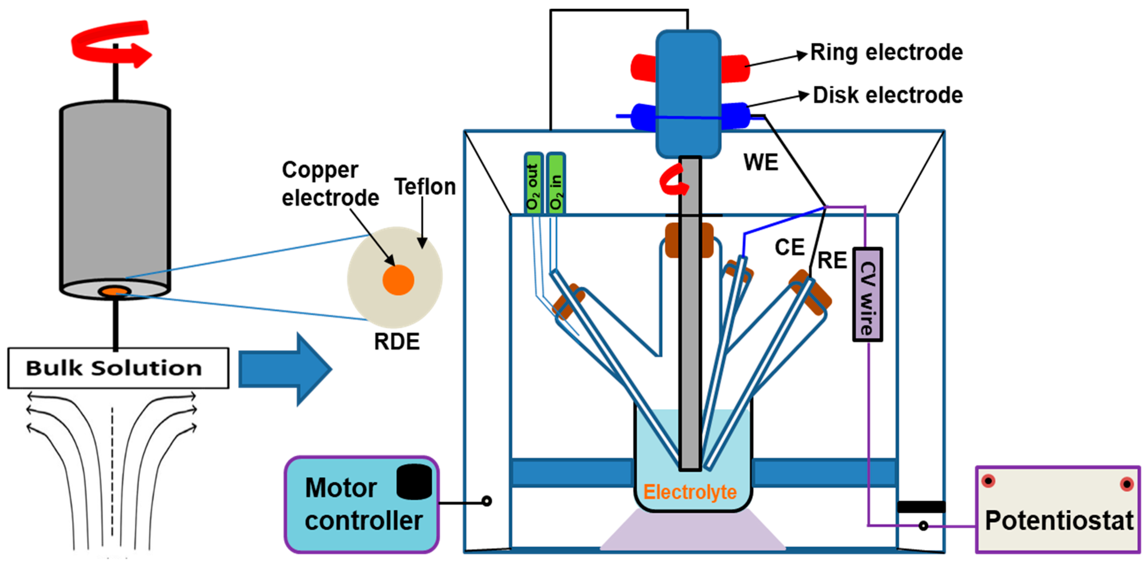
2. Materials and Methods

Cobalt (II) acetate tetrahydrate [(Co(CH3COO)2·4H2O] with 98% purity, TX-100 surfactant (Polyethylene glycol tert-octylphenyl ether) (C14H22O(C2H4O)n) 96%, Acetone (CH3CoCH3) 99.0%, ethanol (CH3CH2OH) 96% sodium tungstate (Na2WO4) 99%, and sodium chloride (NaCl) 99.8%, were all purchased from Sigma-Aldrich, Chennai, India. 5-mercapto-1-phenyl-1H-tetrazole (C7H6N4S) 98% was supplied by TCI chemicals, Chennai, India and a 99.999% pure copper rod was procured from Alfa Aesar, Chennai, India. The chemicals are all analytical grades and were used without any further purification.
The nano-composite inhibitor in the present study is termed C-MPT; prepared by the combination of an inorganic cobalt tungstate (CoWO4) nanoparticle and an organic compound 5-mercapto-1-phenyl-1H-tetrazole (MPT). CoWO4 nanoparticles (NPs) were prepared via precipitation method in a wet solution medium in the presence of TX-100. The procedure is a slight modification of a method used by Kundu et al. [28] and the details are presented in our previously published work [25]. Thereafter, the obtained product was combined with the organic component (MPT). The two compounds gave rise to a nano-composite product, which was formulated by stirring the various concentrations of the synthesized CoWO4 (0.0125, 0.025, and 0.05 wt%) in the presence of TX-100. A fixed amount of MPT (0.018 wt%) was added. Fifteen minute sonication and 1 h stay time was applied to the mixture for quality nucleation; before the electrochemical experiments. During the experiments self-assembly coating was formed on Cu in the solution containing the nano-composite in the electrolyte.
The electrochemical characterizations of Cu in the presence and absence of the newly formulated nano-composite inhibitor were carried out in 3.5 wt% NaCl electrolyte. For comparison purposes, the electrochemical experiment was also carried out with a solution containing 0.018 wt% concentration of 5-mercapto-1-phenyl-1H-tetrazole alone (termed as MPT-alone) in 3.5 wt% NaCl solution to help separate its performance from that of the nano-composite. The electrochemical cell used is made up of Cu RDE working electrode (WE) (see Figure 1) for the setup. The RDE was cut from 5 mm diameter Cu rod with 0.196 cm2 exposed area, the reference electrode (RE) used is the saturated calomel electrode (SCE) and a platinum counter electrode (CE) both were inserted via lugging capillaries to minimize the uncompensated ohmic resistance. The set up in Figure 1 is the connection of a pine instrument rotation control to a Metrohm Autolab potentiostat (PGSTAT302, Utrecht, The Netherlands. EIS was carried out at the OCP over a frequency range (100 kHz–0.01 Hz) at an amplitude of 10 mV. The experiments were carried out under static (0 rpm) and flow conditions by varying the revolution speed per minute (rpm). Thereafter, EIS was carried out at 2400 rpm (the rotation speed of maximum impact) for different immersion duration (0 h, 1 h, and 2 h) and was analyzed using ZSimpWin software 3.2. After OCP stabilization for 1000 s, PDP at a scan rate of 1 mV/s was carried out at potential range of −0.6 to + 0.3 V vs. SCE for both bare Cu and inhibitor coated samples. Although a 1 mV/s is adopted in the present experimentations, it is worth noted that this selection has not provided meaningful distortions in order to determine the corrosion current densities, as previously reported [29,30]. To avoid the limitation of the cathodic reactions, electrolyte solutions were aerated with oxygen gas for 30 min before the experiments [31,32]. All electrochemical experiments were replicated three times and the potential values were measured with respect to SCE.
The morphology and the degree of pitting damage of the coated and uncoated Cu surfaces were visualized using FE-SEM instrument (Carl Zeiss) with Brucker EDAX detector, Jena, Germany.Atomic force microscope (AFM, Nanosurf easyscan 2, Liestal, Switzerland). The oxidation states was investigated using an X-ray photoelectron spectroscopy (XPS) instrument (ESCALAB 250Xi analyzer using Mg-Kα radiation with an energy of 1253.6 eV, California, United States.

3. Results

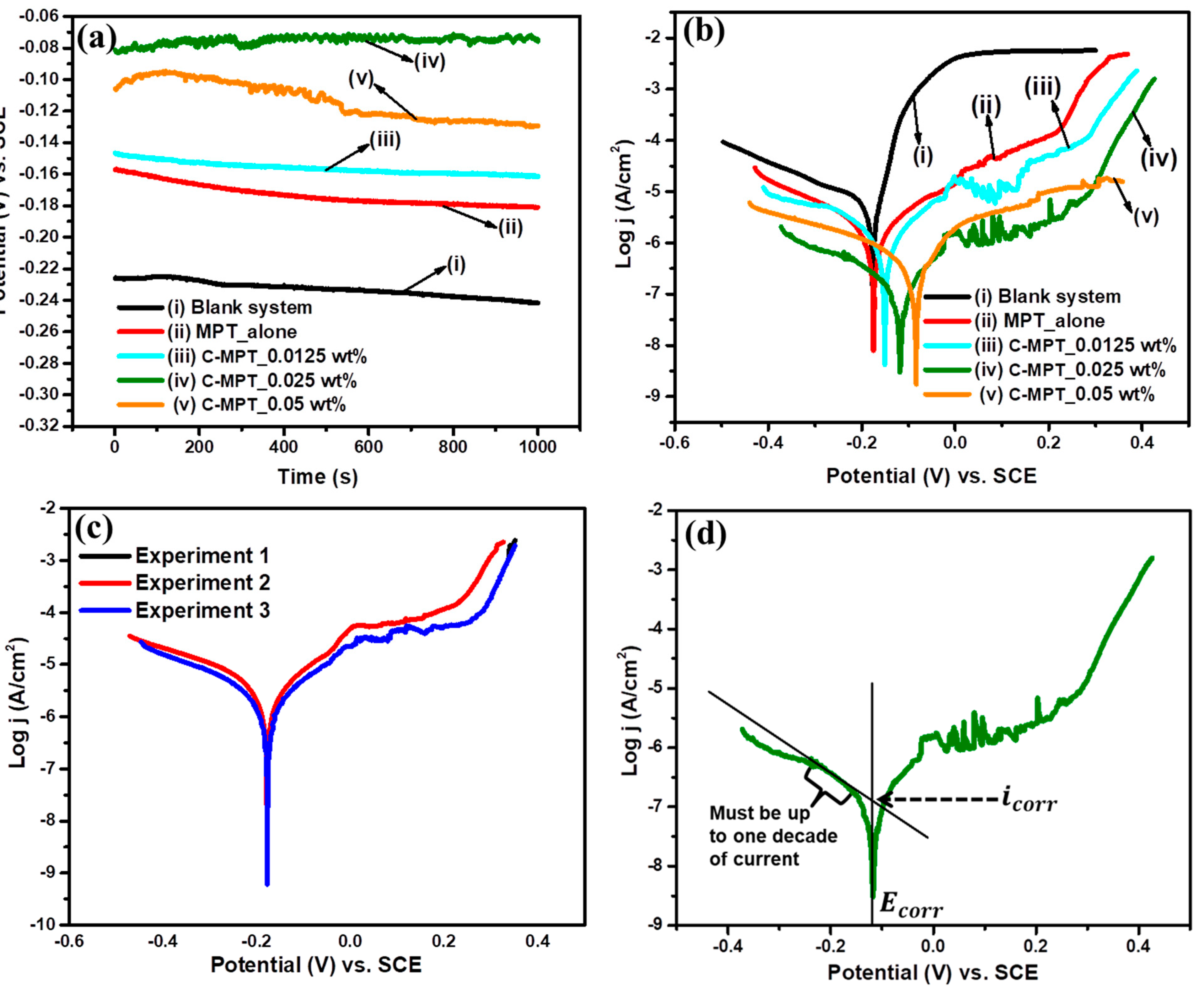
3.1. The Evolution of the Corrosion Potential

The free dissolution of the bare Cu (blank system without inhibitor) and inhibitor coated surfaces were monitored. Figure 2 shows the OCP and PDP plots of bare and C-MPT nano-composite inhibitor coated Cu surface at different concentrations in an aerated 3.5% NaCl at room temperature and rotation rate of 2400 rpm. The OCP values (Figure 2a) show minor variation with time in all the systems from curve i–v, an indication of the stability of the systems, this was achieved prior to further measurements [33]. However, it could be seen that the average OCP value increases per increase in the concentration of the C-MPT nano-composite inhibitor in the corrosive medium. The OCP value tends positive with higher concentration of C-MPT inhibitor up to a threshold of 0.025 wt% above which the OCP decreased, as observed by increasing further to 0.05 wt%. The positive trend is an indication of film growth and surface protection with an increase in C-MPT whereas the eventual decrease in OCP at 0.05 wt% was due to desorption of C-MPT molecules at too high concentration. The concentration of 0.025 wt% appears to show the highest performance for this inhibitor, however, the OCP value alone might not give conclusive data until it is analyzed alongside other electrochemical techniques. Figure 2b is the PDP plots for uninhibited and inhibited surfaces for the measurement of corrosion current density ( i corr ) at the corrosion potential ( E corr ). This confirms the positive shift in E corr as witnessed in the case of the OCP measurement, and further shows that this shift is in line with the reduction in the i corr , which correlates with a reduction in corrosion rate as evidence of copper protection in 3.5% NaCl solution. The corrosion inhibition efficiency is in the order of 84.7, 90.1, 97.4 and 95.5% in line with the i corr reduction. However, a steady increase in the E corr values is observed with increasing concentration up to 0.05 wt% in the case of the polarization results (Figure 2b) unlike OCP case. This could be attributed to accelerated reactions leading to formation of corrosion products due to potential application which could cause minor changes in surface behavior and potential values. The corrosion products was found to synergize with inhibitor film enhancing Cu surface blockage. The formation of corrosion product could be evidenced by the presence of slight peak around 0.0–0.3 V on the anodic side. This product is most likely to be cuprous chloride (CuCl) [25]; helps to passivate the Cu surface. It is interesting to note that there is a wide shift in both cathodic and anodic corrosion current densities with each increase in the C-MPT nano-composite inhibitor in the coating medium with a maximum inhibitory effect of 97.4% at the concentration of 0.025 wt%.
In addition to the cathodic and anodic impact shown by this inhibitor, the shifting of the E corr was found to be less than 85 mV between the bare Cu and the curve of the maximum shift. Thus, this classified the C-MPT nano-composite as a mixed-type inhibitor [34,35,36,37]. Table 2 shows the quantitative values of all the parameters determined via the potentiodynamic polarization. Besides the E corr and i corr there was a decrease or flattening of the cathodic Tafel slope (βc) together with an increase in the corrosion inhibition efficiency (η) with an increase in the inhibitor concentration, which correlates to improved protection in the presence of more amount of the inhibitor. The measurement shows good repeatability in the replicate results as shown in Figure 2c. However, the anodic branch of the corrosion current density of the inhibited systems displays passivation behavior and thus does not have a linear Tafel region. Therefore, the i corr was determined by the extrapolation of cathodic Tafel regionas shown in Figure 2d, as previously reported [38].
To understand the effects of RDE hydrodynamic conditions on the C-MPT nano-composite corrosion inhibition performance, potentiodynamic polarization was carried out at different rotation rates. Figure 3 shows the PDP plots of blank (without inhibitor) and C-MPT nano-composite inhibitor coated Cu surfaces in an aerated 3.5% NaCl at room temperature and rotation rates (0, 200, 1600, and 2400 rpm). The blank system (Figure 3a) displayed the typical corrosion behavior of bare Cu in a 3.5% NaCl solution. Curve i (0 rpm) represents the static condition which shows clearly the Cu dissolution behavior with the exhibition of the active, passive, and transpassive regions as shown by the arrows, respectively. The behavior disappeared by applying the initial rotation at 200 rpm and the Cu dissolution pattern returned at 1600 rpm when the system achieved a quasi-steady state flow which is similar to that of static or 0 rpm. The flow effects become more pronounced again by increasing the rotation rate to a high value of 2400 rpm. The mechanism changes at 200 and 2400 rpm are similar because less time is allowed for film formation due to the high rate of mass transport of the CuCl corrosion product, thus there was a much high dissolution of Cu as indicated by the increased corrosion current density. However, there is a possibility of some Cu corrosion product getting accumulated and stocked at the surface of the spinning electrode, which tends to limit the current at a later stage as indicated by the flat regions of the curves ii and iv. The overall effect of the rotation rate observed is a steady rise in i corr with an eventual initiation of a limiting current end. On the other hand, the C-MPT nano-composite system showed a steady decrease in i corr with the rotation speed (Figure 3b). The presence of the inhibitor clearly changed the Cu dissolution mechanism with a longer passive region indicating the adherence of the inhibitor on the Cu. Minor damage on the film due to the flow effect is observed at the transpassive region where the further increase in the corrosion current density is again observed. The overall effect of the C-MPT nano-composite inhibitor is the steady reduction in the two components of the current generation (anodic and cathodic) with a positive shift in the corrosion potential.

3.2. Electrochemical Impedance Spectroscopy (EIS) Analyses

To reveal the evolution of film growth and resistance with adjustment of the inhibitor concentration electrochemical impedance spectroscopy (EIS) was conducted. Figure 4 shows the Nyquist, and Bode plots of EIS data of bare and C-MPT nano-composite inhibitor coated Cu surface at different concentrations in an aerated 3.5% NaCl at room temperature at a maximum rotation rate (2400 rpm), which is the rpm of highest impact and the results are modelled with the given equivalent circuits. In Figure 4a, the Nyquist plots displayed well-resolved double capacitive loops characteristic of a coated layer on the Cu surface, whereby the first capacitive loop at high frequency represents the presence of film coating and other surfaces related occurrences such as the adsorption of the organic component of the inhibitor. R S is the solution resistance, we observed unusual differences of the impedance values at high frequency relating to R S probably due to the varying concentrations of the C-MPT in the solution. In the long run, the penetration of the electrolyte via the coating pores was observed which was correlated to pore resistance ( R PO ) at prolonged immersion duration. R PO arises due to film resistance ( R f ) to electrolyte penetration, thus R PO //CPE1 is modeled in the equivalent circuit. The second semicircle at the low-frequency end correlates to the resistance to charge transfer ( R ct ) represented in the equivalent circuit as parallel R ct //CPE2 combination. The total resistance ( R p ) therefore is the summation of [38,39,40,41]. The building of higher capacitive loops with rise in the inhibitor concentrations is evidence of film growth leading to a thicker coating on the Cu with the arrival of more C-MPT nano-composite inhibitor molecules at the surface [39].
In this experiment, the Nyquist, Bode modulus and phase angle plots (Figure 4a–c), all show the existence of two time constants for the inhibited surfaces. The first time constant is displayed at the intermediate frequency while the second is at low frequency region [42,43]. The electrochemical reactions related to these two constants exhibited two peaks in these two regions and are correlated to C-MPT film interfacing with the electrolyte. The second time constant is correlated to the interface between the metal and the electrolyte via the film pores, which show CPE behavior parallel to the pore resistance ( R PO ) of the inhibitor film adhering to the metal surface. This allows the formation of small corrosion by-product considering a NaCl solution, the intermediates could be due to the activities of OH and Cl accumulating at the double layer [43], giving rise to cuprous chloride CuCl. The blank system without the inhibitor only exhibited a surface distribution of one time constant at the interface between the metal and electrolyte due to formation of corrosion products film [44,45]. This film is constantly swept off by mass transport on the surface of the spinning electrode under flow condition without allowing the accumulation of this product, leading to the exhibition of one time constant behavior. Thus, for the system with constantly sweeping flow, Cu RDE surface film formation is limited on the blank system, thus the EIS data were modelled with a one-time constant circuit, Figure 4d(i), whereas the C-MPT nano-composite inhibitor coated Cu surfaces was modelled with a two-time constant circuit as shown in Figure 4d(ii).
The highest film formation was observed at a concentration of 0.025 wt%. Therefore, 0.025 wt% was taken as the optimum concentration for the C-MPT nano-composite inhibitor coating, with consequent corrosion suppression performance of 97% on Cu in chloride medium under RDE flow condition as shown in Table 3. In Table 3, it is further shown that the rate of electrolyte penetration into the inhibitor barrier coating was on the decrease with rise in the concentration as seen in the decreasing values of the parameter Y o for both CPE1 and 2. These findings were supported by the Bode plots Figure 4b,c representing the Bode modulus and phase angle, respectively. The modulus plot shows that the logarithmic value of IZI for the best performing concentration (0.025 wt%) of the inhibitor is above 4.5 Ω·cm2, whereas the phase angle (−ø) is as high as 85 degrees.

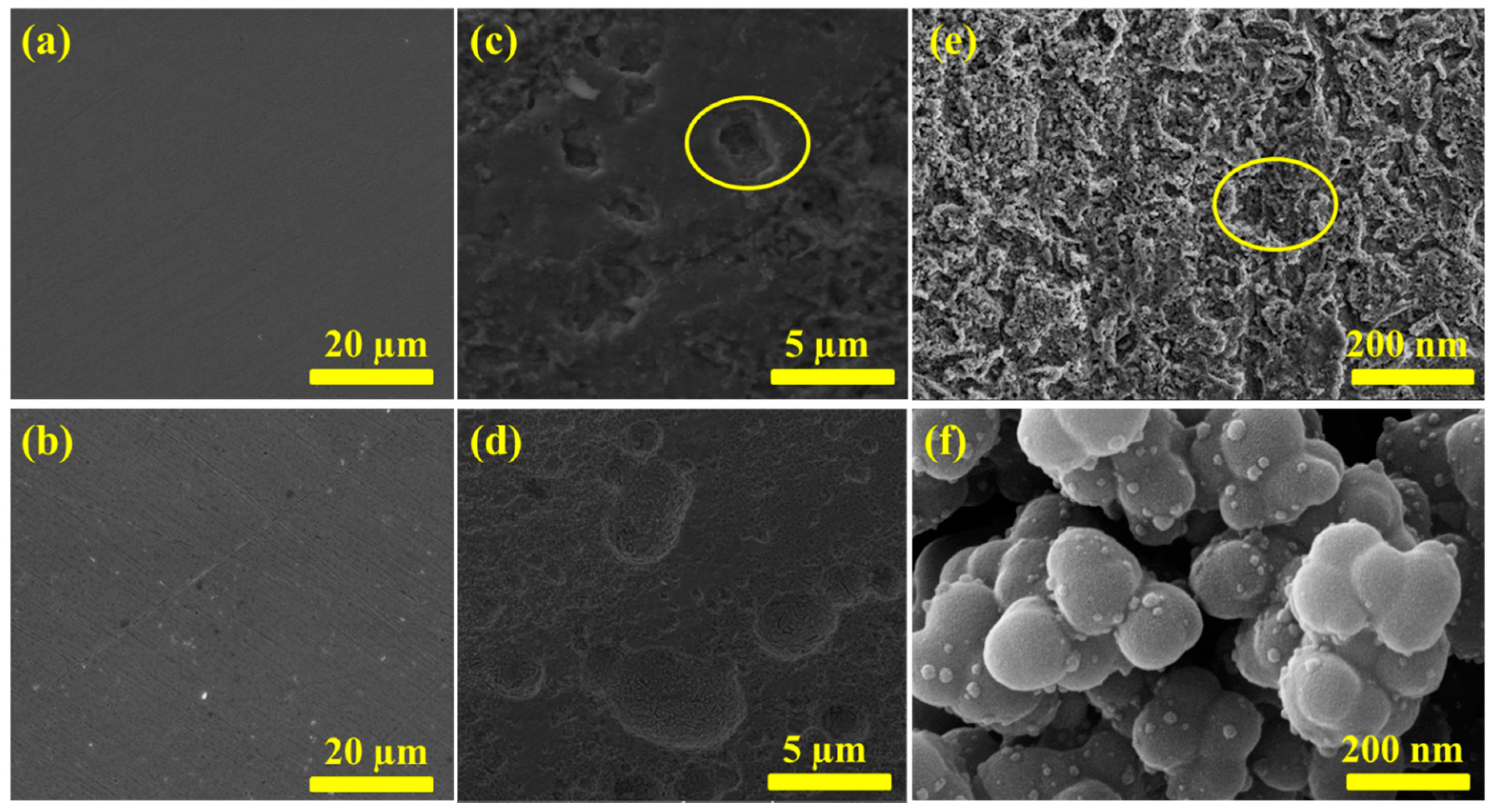
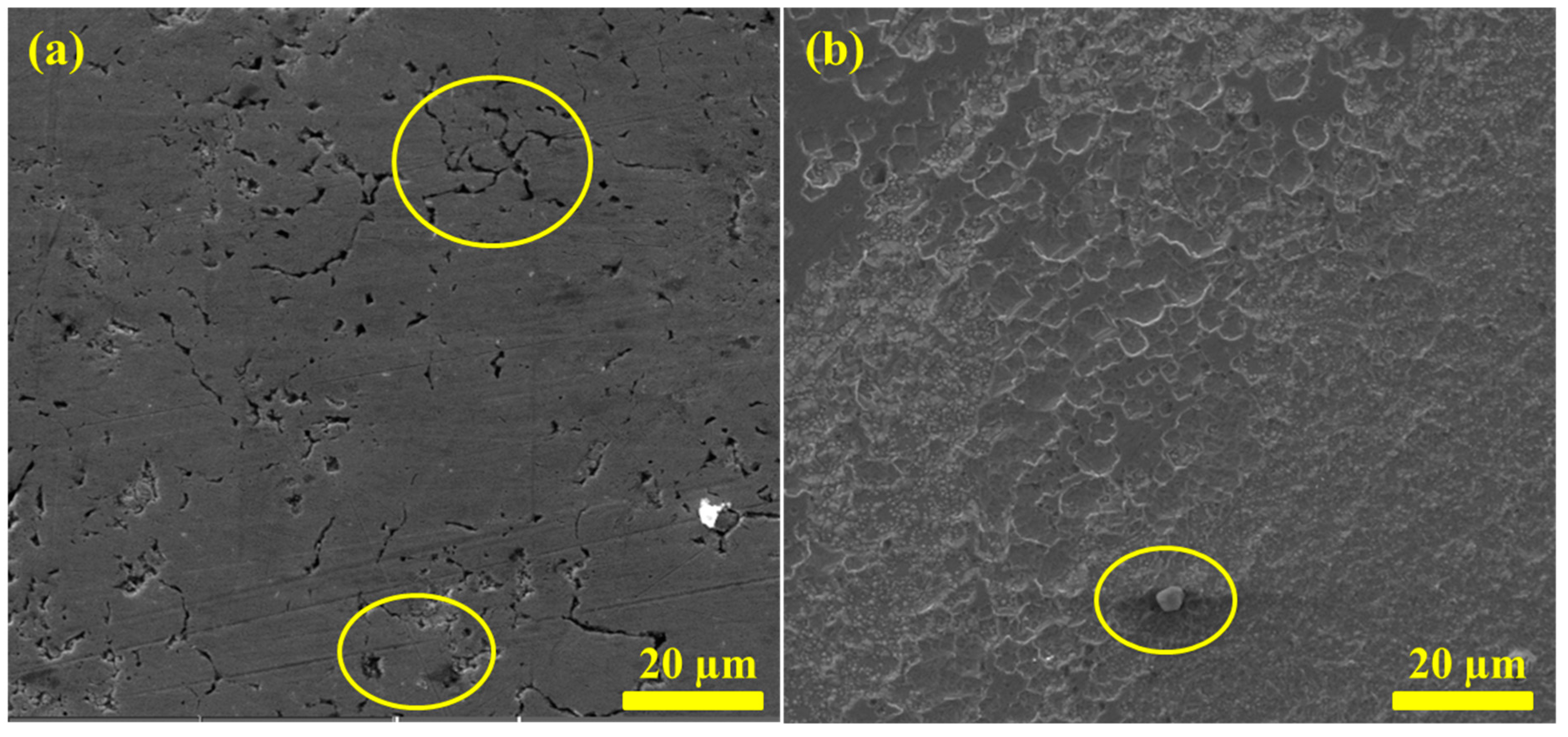
3.3. Post Corrosion SEM and FE-SEM Analyses of Immersed Surfaces

To have a better view of the Cu dissolution behavior with and without inhibitor coatings; imaging of the coated and uncoated Cu was implemented. Figure 5 displays the SEM and FE-SEM images of bare surfaces pre and post immersion in blank and C-MPT nano-composite inhibitor solutions of an aerated chloride solution at a rotation rate of 2400 rpm. Bare surfaces before immersion show no evidence of corrosion or film formation, as expected (see Figure 5a,b). However, by immersing in the corrosive medium, the blank (Figure 5c) displays a huge presence of corrosion pits after 1 h, whereas minor pits are observed on the Cu from the C-MPT nano-composite inhibitor system (Figure 5d) as viewed by SEM.
To observe more information at the nano range, the same surfaces for the blank and C-MPT systems were viewed with FE-SEM instrument Figure 5e,f, respectively. This confirmed the formation of stable pits and high corrosion damage on the bare Cu immersed without inhibitor. The corrosion rate, metastable pits, and surface morphology of the bare Cu surfaces were significantly different from the C-MPT nano-composite inhibitor coated metal, which shows no corrosion product. Rather, the system with C-MPT nano-composite inhibitor revealed the presence of nanoparticles from the inorganic component (CoWO4) of high surface area that allowed the adsorption of the organic compound (5-mercapto-1-phenyl-1 H-tetrazolederivative, MPT) found sitting all over the particle spaces and the entire materials were coated on the metal. The formation of this nano-composite inhibitor coating structure on the Cu surface was surely responsible for the protection efficiency witness in the present research.

3.4. Effect of Immersion Duration on Coating Performance

To further investigate the capability of this coating generated naturally from the wet chemical solution medium, the influence of immersion duration was monitored by extending the coating time from 1 h to 2 h. Figure 6 shows the SEM images taken on the bare and C-MPT nano-composite inhibitor coated Cu surfaces, after 2 h immersion in an aerated chloride solution at 2400 rpm in the presence and absence of the inhibitor.
Figure 6a revealed huge pitting propagation after 2 h on Cu in the absence of the C-MPT nano-composite inhibitor, however, these pits were found to be absent in the case of coated surface (Figure 6b) by the introduction of the C-MPT nano-composite inhibitor. The evidence of coating and minor cracks were observed. It further revealed the facile formation of film coating within few hours by the new nano-composite material compared to the usual 24 h for conventional self-assembly methods [25,26]. Moreover, the ability of the formed coating to block the penetration of chloride ions by the observed barrier formation might be a solution to pinhole leaks, which is the problem associated with Cu pitting corrosion in potable water systems. Bearing this in mind, more in-depth analyses of the pit nature are carried out in this research.

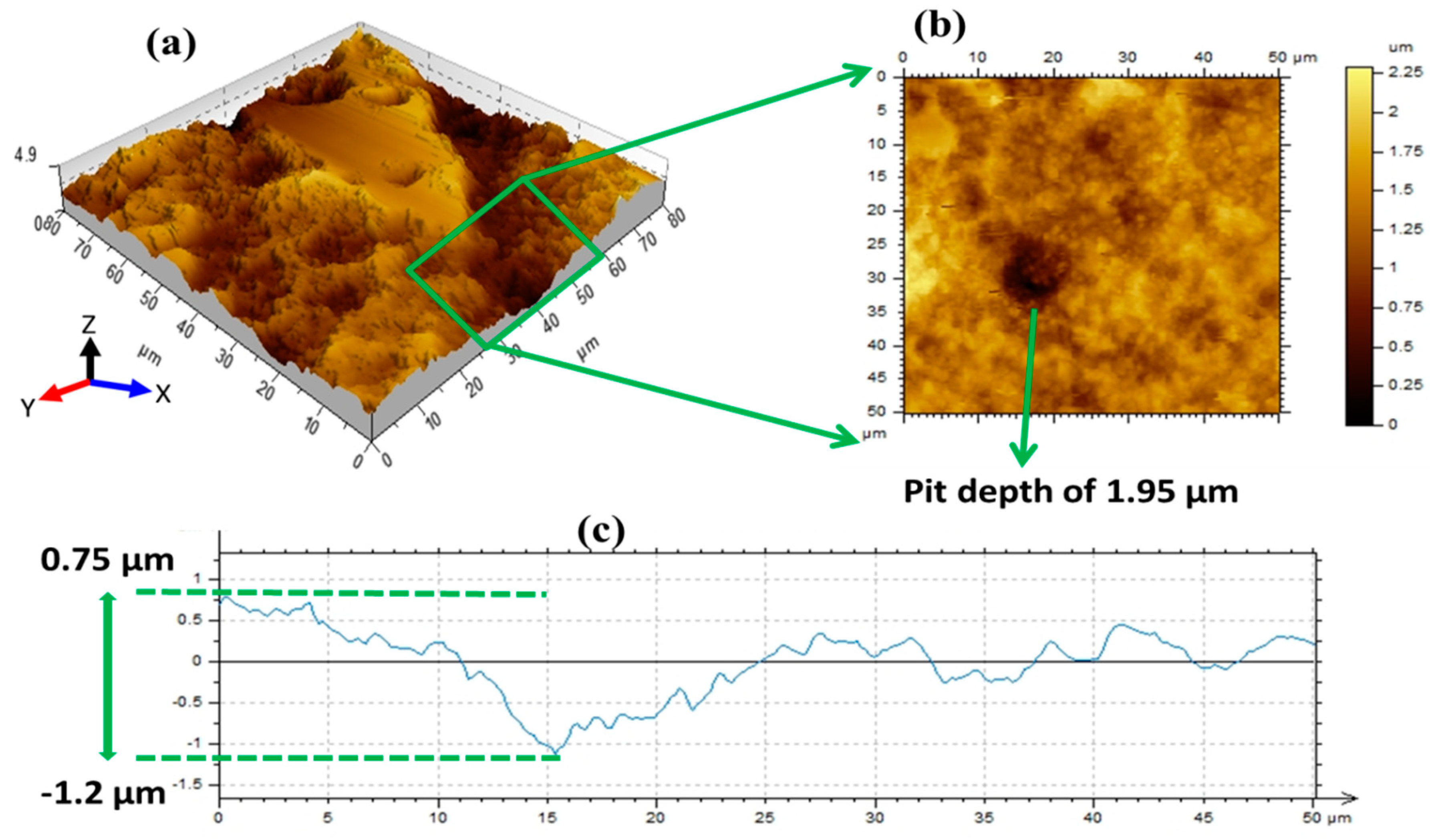
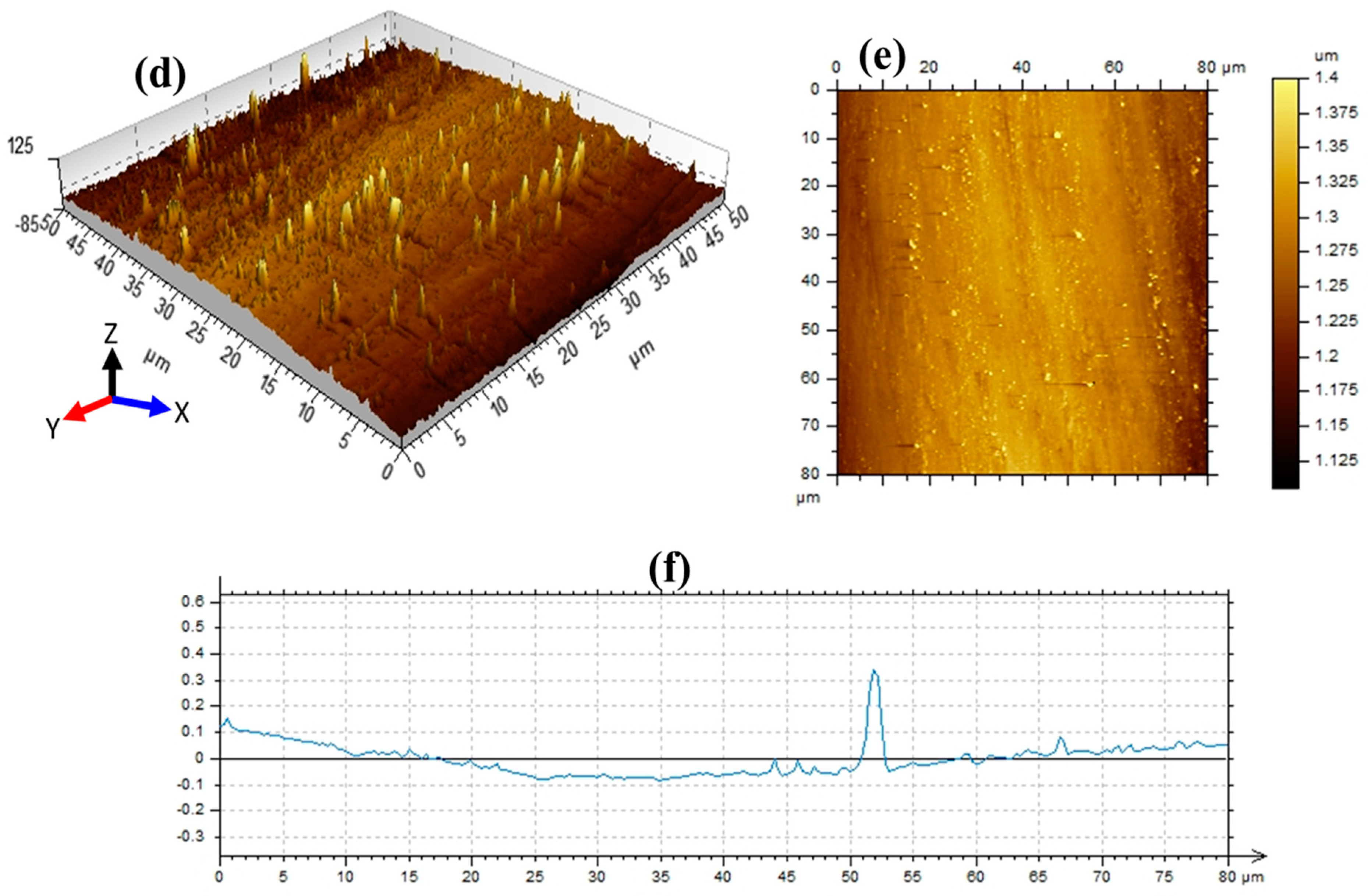
3.5. AFM Analyses of the Coated and Uncoated Cu Surfaces

In the laboratory, it is difficult to reproduce the precise conditions that create pinholes in the site environments. Suspected issues are chlorinated water of high pH and low alkalinity as the only causes [2,46]. However, research has also shown that Cu pitting in chlorinated water is accelerated by flow velocities, and immersion duration [2]. Figure 7 shows the AFM micrographs representing the 3D, 2D, and roughness profiles of bare Cu without inhibitor coating and C-MPT nano-composite coated surfaces after 2 h immersion in an aerated chloride medium with and without inhibitor at RDE rotation rate of 2400 rpm. The result reveals that large pits are developed on bare Cu after 2 h, as displayed in the 3D image of Figure 7a. To profile the depth of this hole, a 2D projection was made for a single hole Figure 7b, and from this, the depth of the largest pit was found to be approximately 1.95 μm after 2 h duration with evidence of high roughness on the entire profiled region (Figure 7c), this is a dangerous occurrence. However, it is good to note that by the introduction of C-MPT nano-composite inhibitor (Figure 7d) the damage was averted. The vertical orientation of the inhibitor particles were observed on the Cu surface without evidence of pit formation. Both uniform and localized corrosion are strongly mitigated by the inhibitor. This is much clearer in the 2D image (Figure 7e), which shows that the Cu surface had zero pit formation in the presence of the C-MPT nano-composite coating. The profiling of this inhibitor coated surface (Figure 7f) shows that surface roughness was highly reduced as evidence of the C-MPT inhibitor corrosion protection ability on Cu surface in aggressive 3.5% NaCl for up to 2 h immersion duration at rotation rate of 2400 rpm.

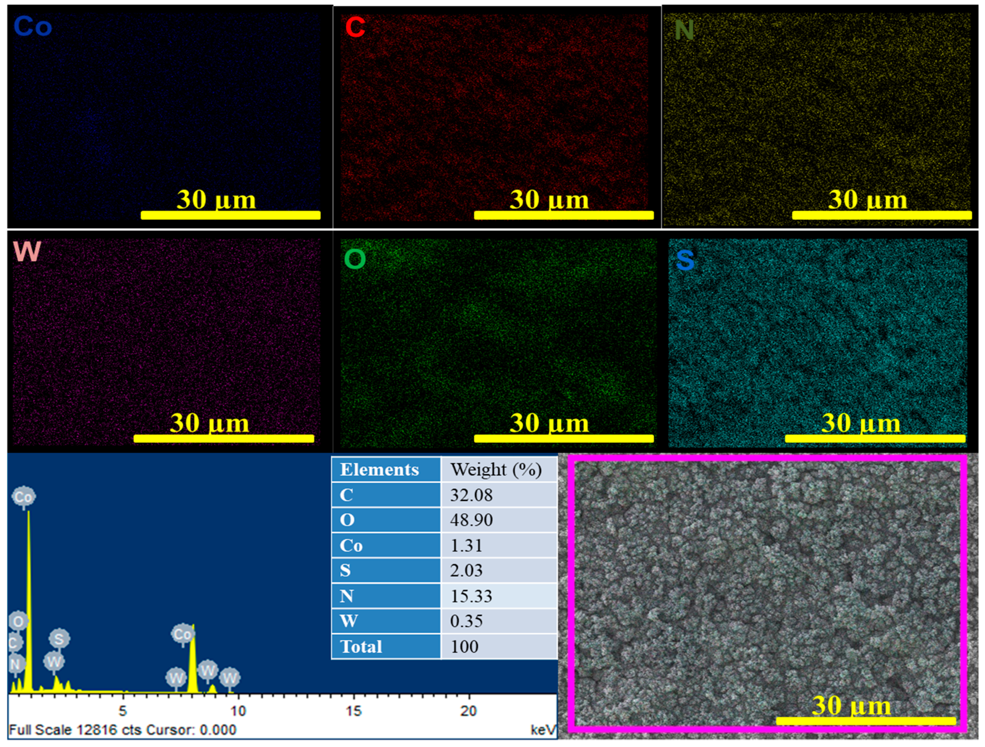
3.6. Elemental Color Mapping and EDAX Analyses of Coated Surfaces

The elemental composition of the coated surface and the spread of the individual component elements are very crucial in the corrosion behavior of the metal substrate and thus were determined by EDAX and color map techniques. Figure 8 shows the FE-SEM color mapping and EDAX of the elements in the C-MPT nano-composite inhibitor coated Cu surfaces after 2 h immersion in an aerated 3.5% NaCl solution containing the inhibitor at room temperature and rotation rate of 2400 rpm. The detected elements are; Co, W, C, O, S, and N as expected from the nano-composite containing (CoWO4 and C7H6N4S). All the elements showed good spread on the Cu surface as confirmed via the color mapping.

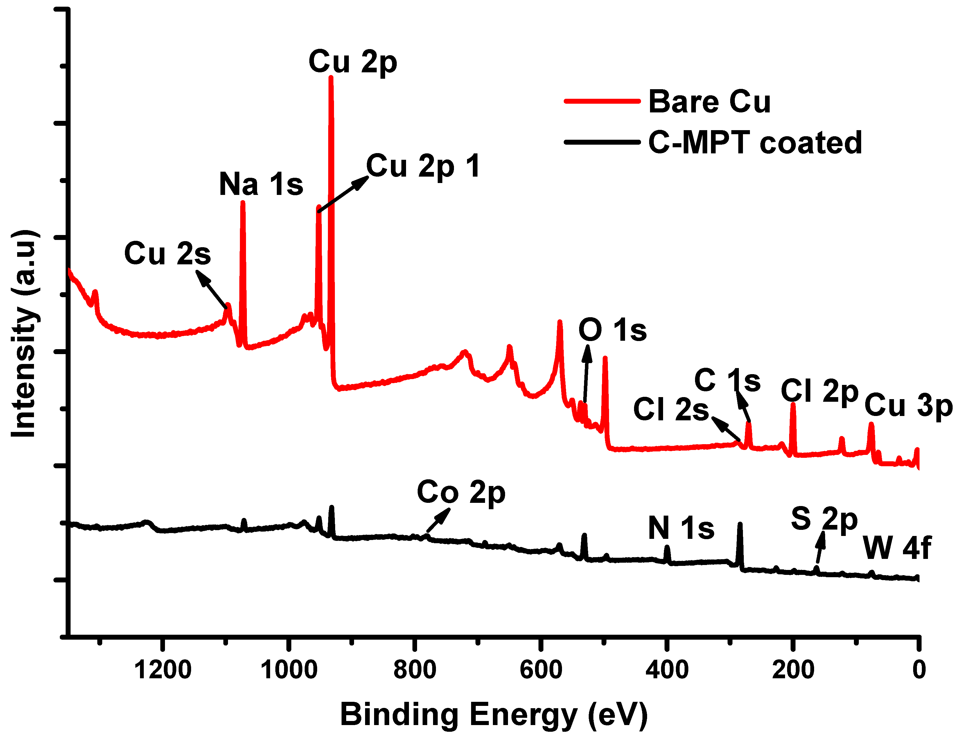
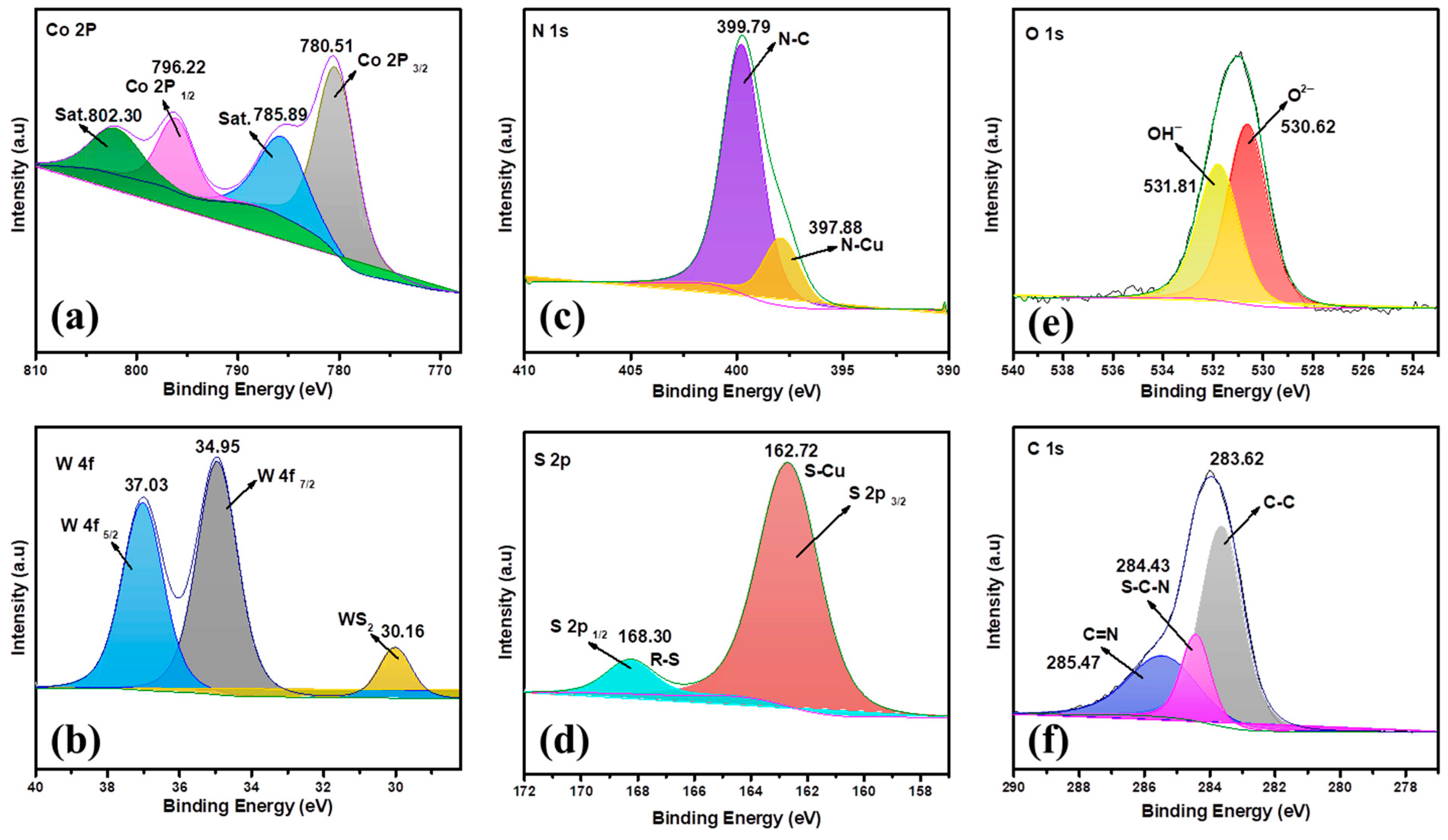
3.7. Post Corrosion XPS Analysis of Coated and Uncoated Cu Surfaces

Further, elemental and oxidation state analyses of the elements detected were carried out on the filmed and unfilmed Cu surface using XPS analysis. Figure 9 is the survey spectra of the elements on bare Cu and C-MPT nano-composite inhibitor coated surfaces after immersion in an aerated chloride medium with and without the inhibitor at room temperature and rotation speed of 2400 rpm. The spectrum of bare Cu showed evidence of corrosion products with a very high intensity of Cu peaks at binding energy approximately 932.76 and 952.33 eV correlated to Cu 2p and Cu 2p1, respectively, both as a result of Cu leaching in the solution medium due to high rate of dissolution in the absence of the inhibitor [47]. However, by introducing the C-MPT nano-composite inhibitor, the Cu surface got coated by this material leading to the shielding of the substrate. The coated surface shows no presence of Cu corrosion products with highly reduced intensity of Cu peak as evidence of suppression of Cu leaching; only the elements from the C-MPT inhibitor (Co, W, C, O, S and N) were detected confirming the FE-SEM EDAX elemental analysis as already discussed.
Further, the high-resolution analysis of the elements in the C-MPT inhibitor was carried out to understand the oxidation states of the detected elements. Figure 10 shows the high-resolution XPS spectra of the elements on the C-MPT nano-composite inhibitor coated on Cu surface after immersion in an aerated 3.5% NaCl containing the inhibitor at room temperature and rotation rate of 2400 rpm, Figure 10a shows the spectra of Co 2pwith the spin-orbital coupling deconvoluted to Co 2p1/2 and Co 2p3/2 at binding energies 796.22 and 780.51 eV, respectively. The characteristic satellite peaks of Co 2p1/2 and Co 2p3/2 are equally observed at binding energies 802.30 and 785.89 eV, respectively, confirming the presence of Co. Figure 10b displays the spectra of W6+ with spin-orbital coupling at binding energies 34.95 and 37.03 eV assigned to W 4f7/2 and, W 4f5/2,respectively, with an extra peak occurring at 30.16 eV corresponding to WS2,confirming the presence of the tungstate in the film and indicates the interaction between the organic compound containing thiol group (R-SH) and the tungstate part of the nanoparticles. Other elements such as N 1s (Figure 10c) is fitted with two peaks 399.79 ± 0.2 and 397.88 ± 0.1 eV corresponding to the tetrazole and metal nitride, respectively, confirming the bond interaction between the organic part of the nano-composite and the Cu surface which is crucial for the film adherence and high corrosion inhibition efficiency [48].
The S 2p peak at 168.30 eV is correlated to thiol species (R-S) and the 162.72 eV corresponds to metal sulfide (S-Cu) another strong binding site for the nano-composite coating (Figure 10d). O 1s (Figure 10e) the broad peaks at binding energies 530.62 ± 0.21 eV correlated to O2− in the oxides and 531.81 ± 0.1 eV for metal hydroxides resulting from solution chemical reaction with the Cu metal before full film formation. C 1s signal (Figure 10f) at binding energies 285.47 ± 0.2, 284.43 ± 0.2, and 283.62 ± 0.2 eV are assigned to the phenyl ring/or C=N, S-C-N, and C-C carbon bonds, respectively, all from the organic part of the nano-composite film coating. The overall analysis confirms the deposition of C-MPT nano-composite inhibitor coating on Cu surface as responsible for the observed corrosion inhibition of the metal in chloride medium solution under flow conditions.

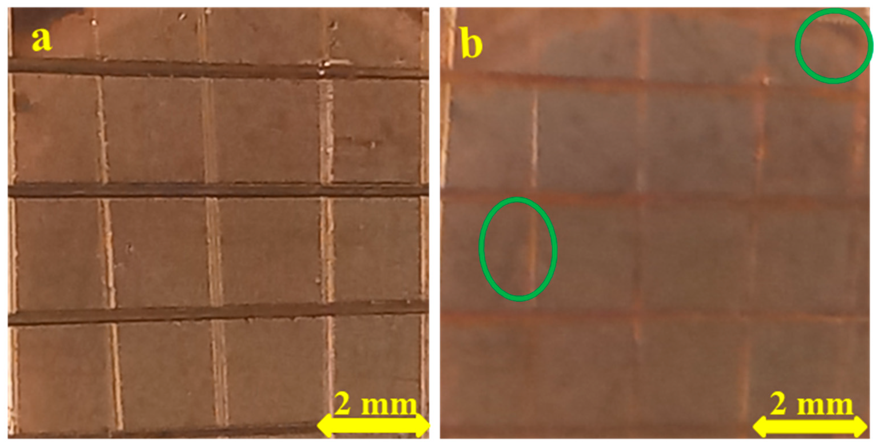
3.8. ASTM Standard Adhesion Tape Test

Adhesion is an important index for the evaluation of anticorrosive coatings and is used in our study to monitor the C-MPT nano-composite inhibitor coating persistence on the Cu surface. Good adhesion not only inhibits the penetration of corrosion causing species such as dissolved oxygen and chloride ions, but also prevents pitting corrosion propagation. Figure 11 shows the visual images of the coatings cut into grids before and after the application of tape tests (Figure 11a,b), respectively, as per ASTMD 3359-97 standards.
No coating detachment was observed, but only a minor imparts that led to the extension of the coatings into the marked grooves as a result of applied pressure before tape pulling. This is to ensure proper sticking of the tape. Visibly, only two spots showed minor intention to initiate delamination, thus indicating excellent adhesion of the nano-composite on the Cu surface.

4. Discussion

The penetration of chloride ions through to the metal surface by tunneling via coating pores causes corrosion attacks during reaction with the metal ions. The reaction with Cu gives rise to the formation of unstable cuprous chloride (CuCl) film, which gives temporal passivation and quickly dissolves via cuprous complex (CuCl2) to give way to further dissolution of the bare Cu metal [49]. There would be a rise in the corrosion current after temporal passivation due to the breakdown of the cuprous chloride layer, which gives way to a transpassive region found in the bare Cu system (Figure 3a). This stage translates to the dissolution process of Cu via cupric ion (Cu2+). The high intensity of current in this region is not only correlated to film breakdown, but also to the localized concentrated attack of the Cu surface leading to stable pit formation as witnessed in the AFM surface imaging (Figure 7). The observed pit depth of 1.96 μm is very large, yet not visible to the unaided eye. The implication is that the damage due to pitting corrosion will remain undetected in the field environment, thus leading to premature or accidental breakdown, loss of infrastructural integrity, and high occupational risk. However, the C-MPT inhibitor in the present investigation reversed this dangerous attack on the Cu surface through a synergy between CoWO4 and MPT deposits as shown by FE-SEM analysis (Figure 5f). The active region in Figure 3a is the zone of high dissolution of Cu into solution as cuprous ions (Cu+), at the passive region the formation of CuCl film takes place between Cu+ and Cl. This process results in a limiting effect on the corrosion current density before the transpassive region, the unstable CuCl film get dissolved via CuCl2 complex followed by cupric ion (Cu2+) formation, leading to further increase in the anodic current density generation [49]. However, by increasing the rotation speed, these characteristic phenomena gradually disappear, showing the dependency of Cu dissolution on the rotation rate. An increase in the rotation rate thus leads to a higher dissolution region in the bare system with the diminished passive region as shown by curve iii (Figure 3a) at 1600 rpm. The inhibited Cu system (Figure 3b) shows no dependence on the rotation rate as the surface is shielded from the corrosive electrolyte by the inhibitor coating. This equally confirms that the inhibitor is effective and maintains persistence on the metal surface even after 2 h extended immersion under flow (see surfaces in Figure 6). The thorough analysis of the C-MPT inhibitor in the present work reveals the effectiveness of this inhibitor for the protection of Cu under the tested aggressive environmental conditions.

5. Conclusions

In conclusion, electrochemical methods and advanced surface techniques were employed to investigate the effectiveness of a wet chemical coating made of C-MPT nano-composite inhibitor on Cu for corrosion mitigation. The synergy from the inhibitor combination, film thickness, and surface morphology of the nano-composite was responsible for curbing the metal degradation. The inhibitor curbed both localized and uniform corrosion in the presence of chloride ions and hydrodynamic flow. Therefore, the present report highlights the following key points:
  • Nano-composite film was successfully fabricated on the copper surface using synthesized CoWO4 in synergy with 5-mercapto-1-phenyl-1H-tetrazole (MPT) via a wet chemical coating method.
  • SEM and AFM analysis revealed the development of corrosion pits with a maximum depth of 1.95 µm on the uncoated copper after 2 h immersion duration due to chloride ion penetration which was aggravated by mass transport under hydrodynamic flow conditions.
  • However, by the introduction of C-MPT nano-composite corrosion inhibitor, there was a facile and natural fabrication of film, which grew into a stable barrier coating on Cu surface leading to zero pit formation as evidence of effective protection.
  • Electrochemical investigation showed that the inhibitor reduced the corrosion rate by inhibiting both cathodic and anodic reactions with a consequent reduction in corrosion current density from 34.5 to 1.02 µA cm−2, with a potential shift of less than 85 mV vs. SCE, which defines it as a mixed-type inhibitor.

Author Contributions

Conceptualization, V.I.C.; methodology, V.I.C.; software, R.C.B.; validation, V.I.C.; formal analysis, V.I.C.; investigation, V.I.C.; resources, R.C.B.; data curation, V.I.C.; writing—original draft preparation, V.I.C.; writing—review and editing, R.C.B.; visualization, V.I.C.; supervision, R.C.B.; funding acquisition, R.C.B. and V.I.C. All authors have read and agreed to the published version of the manuscript.

Funding

This work was supported by Council of Scientific and Industrial Research (CSIR), India, and The World Academy of Sciences (TWAS Fellowship), Italy, Award number 22/FF/CSIR-TWAS/2016 and The APC was funded by the Science and Engineering Research Board, DST India under the Extramural Research (EMR) funding scheme grant number EMR/2016/003316).

Data Availability Statement

The data in this work are part of a Ph.D. research and will be available at the time of request from the corresponding author.

Acknowledgments

The World Academy of Sciences (TWAS), Italy and the Council of Scientific and Industrial Research (CSIR), India, are fully acknowledged by Chukwuike for the CSIR-TWAS Postgraduate Fellowship (Award No.22/FF/CSIR-TWAS/2016) for the pursuit of his Ph.D. research program in CSIR-CECRI, India. This research was equally supported by the Science and Engineering Research Board, DST India under the Extramural Research (EMR) funding scheme (EMR/2016/003316). All the authors are grateful to the Central Instrument Facility (CIF), CSIR-CECRI for extending the characterization facilities (CSIR-CECRI Manuscript Communication Number: CECRI/PESVC/Pubs./2021-123).

Conflicts of Interest

The authors declare no conflict of interest.

References

  1. Arjmand, F.; Adriaens, A. Influence of pH and chloride concentration on the corrosion behavior of unalloyed copper in NaCl solution: A comparative study between the micro and macro scales. Materials 2012, 5, 2439–2464. [Google Scholar] [CrossRef] [Green Version]
  2. Sarver, E.; Edwards, M. Inhibition of copper pitting corrosion in aggressive potable waters. Int. J. Corros. 2012, 2012, 857823. [Google Scholar] [CrossRef] [Green Version]
  3. Frankel, G.S. Pitting Corrosion of Metals: A Review of the Critical Factors. J. Electrochem. Soc. 1998, 145, 2186–2198. [Google Scholar] [CrossRef]
  4. De Chialvo, M.R.G.; Salvarezza, R.C.; Vasquez Moll, D.; Arvia, A.J. Kinetics of passivation and pitting corrosion of polycrystalline copper in borate buffer solutions containing sodium chloride. Electrochim. Acta 1985, 30, 1501–1511. [Google Scholar] [CrossRef] [Green Version]
  5. Ha, H.M.; Scully, J.R. Effects of phosphate on pit stabilization and propagation in copper in synthetic potable waters. Corrosion 2013, 69, 703–718. [Google Scholar] [CrossRef]
  6. Loto, R.T. Electrochemical analysis of the corrosion inhibition effect of trypsin complex on the pitting corrosion of 420 martensitic stainless steel in 2M H2SO4 solution. PLoS ONE 2018, 13, e0195870. [Google Scholar] [CrossRef] [PubMed] [Green Version]
  7. El Warraky, A.; El Shayeb, H.A.; Sherif, E.M. Pitting corrosion of copper in chloride solutions. Anti-Corros. Methods Mater. 2004, 51, 52–61. [Google Scholar] [CrossRef]
  8. Marcus, P.; Maurice, V.; Strehblow, H.H. Localized corrosion (pitting): A model of passivity breakdown including the role of the oxide layer nanostructure. Corros. Sci. 2008, 50, 2698–2704. [Google Scholar] [CrossRef]
  9. Li, S.; Teague, M.T.; Doll, G.L.; Schindelholz, E.J.; Cong, H. Interfacial corrosion of copper in concentrated chloride solution and the formation of copper hydroxychloride. Corros. Sci. 2018, 141, 243–254. [Google Scholar] [CrossRef]
  10. Cong, H.; Scully, J.R. Effect of Chlorine Concentration on Natural Pitting of Copper as a Function of Water Chemistry. J. Electrochem. Soc. 2010, 157, C200–C211. [Google Scholar] [CrossRef]
  11. Dartmann, J.; Sadlowsky, B.; Dorsch, T.; Johannsen, K. Copper corrosion in drinking water systems—Effect of pH and phosphate-dosage. Mater. Corros. 2010, 61, 189–198. [Google Scholar] [CrossRef]
  12. Tang, Y.; Zuo, Y.; Wang, J.; Zhao, X.; Niu, B.; Lin, B. The metastable pitting potential and its relation to the pitting potential for four materials in chloride solutions. Corros. Sci. 2014, 80, 111–119. [Google Scholar] [CrossRef]
  13. Chen, Z.; Zhang, G.; Bobaru, F. The Influence of Passive Film Damage on Pitting Corrosion. J. Electrochem. Soc. 2016, 163, C19–C24. [Google Scholar] [CrossRef]
  14. Papadopoulou, O.; Vassiliou, P. The Influence of Archaeometallurgical Copper Alloy Castings Microstructure towards Corrosion Evolution in Various Corrosive Media. Corros. Mater. Degrad. 2021, 2, 227–247. [Google Scholar] [CrossRef]
  15. Croll, S.G. Surface roughness profile and its effect on coating adhesion and corrosion protection: A review. Prog. Org. Coat. 2020, 148, 105847. [Google Scholar] [CrossRef]
  16. Song, G.-L.; Feng, Z. Modification, degradation and evaluation of a few organic coatings for some marine applications. Corros. Mater. Degrad. 2020, 1, 408–442. [Google Scholar] [CrossRef]
  17. Chen, K.; Zhou, S.; Wu, L. Self-healing underwater superoleophobic and antibiofouling coatings based on the assembly of hierarchical microgel spheres. ACS Nano 2016, 10, 1386–1394. [Google Scholar] [CrossRef] [PubMed]
  18. Balbo, A.; Chiavari, C.; Martini, C.; Monticelli, C. Effectiveness of corrosion inhibitor films for the conservation of bronzes and gilded bronzes. Corros. Sci. 2012, 59, 204–212. [Google Scholar] [CrossRef]
  19. Chen, W.; Hong, S.; Li, H.B.; Luo, H.Q.; Li, M.; Li, N.B. Protection of copper corrosion in 0.5M NaCl solution by modification of 5-mercapto-3-phenyl-1,3,4-thiadiazole-2-thione potassium self-assembled monolayer. Corros. Sci. 2012, 61, 53–62. [Google Scholar] [CrossRef]
  20. Tian, H.; Li, W.; Cao, K.; Hou, B. Potent inhibition of copper corrosion in neutral chloride media by novel non-toxic thiadiazole derivatives. Corros. Sci. 2013, 73, 281–291. [Google Scholar] [CrossRef]
  21. Wei, N.; Jiang, Y.; Liu, Z.; Ying, Y.; Guo, X.; Wu, Y.; Wen, Y.; Yang, H. 4-Phenylpyrimidine monolayer protection of a copper surface from salt corrosion. RSC Adv. 2018, 8, 7340–7349. [Google Scholar] [CrossRef] [Green Version]
  22. Shevtsov, D.; Kozaderov, O.; Shikhaliev, K.; Komarova, E.; Kruzhilin, A.; Potapov, A.; Prabhakar, C.; Zartsyn, I. 3-Sulphinyl-5-amino-1H-1,2,4-triazoles as inhibitors of copper corrosion. Appl. Sci. 2019, 9, 4882. [Google Scholar] [CrossRef] [Green Version]
  23. Martinović, I.; Zlatić, G.; Pilić, Z.; Šušić, L.; Kowalska, O.; Petrović, D.; Falak, F.; Mišković, J. Self assembled monolayers of alkanethiol as inhibitors against copper corrosion in synthetic acid rain. Int. J. Electrochem. Soc. 2019, 14, 4206–4215. [Google Scholar]
  24. Durainatarajan, P.; Prabakaran, M.; Ramesh, S. Self-assembled monolayers of novel imidazole derivative on copper surface for anticorrosion protection in neutral medium. J. Adhes. Sci. Technol. 2021, 35, 2580–2601. [Google Scholar] [CrossRef]
  25. Chukwuike, V.I.; Sam Sankar, S.; Kundu, S.; Barik, R.C. Nanostructured cobalt tungstate (CoWO4: A highly promising material for fabrication of protective oxide film on copper in chloride medium. J. Electrochem. Soc. 2019, 166, 631–641. [Google Scholar] [CrossRef]
  26. Mihit, M.; Salghi, R.; El Issami, S.; Bazzi, L.; Hammouti, B.; Addi, E.A.; Kertit, S. A study of tetrazoles derivatives as corrosion inhibitors of copper in nitric acid. Pigment Resin Technol. 2006, 35, 151–157. [Google Scholar] [CrossRef]
  27. Jafari, H.R.; Davoodi, A.; Hosseinpour, S. Effect of Fluid Flow on the Corrosion Performance of as-Cast and Heat-Treated Nickel Aluminum Bronze Alloy (UNS C95800) in Saline Solution. Corros. Mater. Degrad. 2021, 2, 61–77. [Google Scholar] [CrossRef]
  28. Kumaravel, S.; Thiruvengetam, P.; Ede, S.R.; Karthick, K.; Anantharaj, S.; Sam Sankar, S.; Kundu, S. Cobalt tungsten oxide hydroxide hydrate (CTOHH) on DNA scaffold: An excellent bi-functional catalyst for oxygen evolution reaction (OER) and aromatic alcohol oxidation. Dalton Trans. 2019, 48, 17117–17131. [Google Scholar] [CrossRef]
  29. Zhang, X.L.; Jiang, Z.H.; Yao, Z.P.; Song, Y.; Wu, Z.D. Effects of scan rate on the potentiodynamic polarization curve obtained to determine the Tafel slopes and corrosion current density. Corros. Sci. 2009, 51, 581–587. [Google Scholar] [CrossRef]
  30. McCafferty, E. Validation of corrosion rates measured by the Tafel extrapolation method. Corros. Sci. 2005, 47, 3202–3215. [Google Scholar] [CrossRef]
  31. Kear, G.; Barker, B.D.; Stokes, K.R.; Walsh, F.C. Corrosion and impressed current cathodic protection of copper-based materials using a bimetallic rotating cylinder electrode (BRCE). Corros. Sci. 2005, 47, 1694–1705. [Google Scholar] [CrossRef]
  32. Deslouis, C.; Tribollet, B.; Mengoli, G.; Musiani, M.M. Electrochemical behavior of copper in neutral aerated chloride solution II. Impedance investigation. J. Appl. Elelctrochem. 1988, 18, 384–393. [Google Scholar] [CrossRef]
  33. Sabet Bokati, K.; Dehghanian, C.; Yari, S. Corrosion inhibition of copper, mild steel and galvanically coupled copper-mild steel in artificial sea water in presence of 1H-benzotriazole, sodium molybdate and sodium phosphate. Corros. Sci. 2017, 126, 272–285. [Google Scholar] [CrossRef]
  34. Tan, B.; Xiang, B.; Zhang, S.; Qiang, Y.; Xu, L.; Chen, S.; He, J. Papaya leaves extract as a novel eco-friendly corrosion inhibitor for Cu in H2SO4 medium. J. Colloid Interface Sci. 2021, 582, 918–931. [Google Scholar] [CrossRef] [PubMed]
  35. Qiang, Y.; Zhang, S.; Xu, S.; Yin, L. The effect of 5-nitroindazole as an inhibitor for the corrosion of copper in a 3.0% NaCl solution. RSC Adv. 2015, 5, 63866–63873. [Google Scholar] [CrossRef]
  36. Verma, C.B.; Quraishi, M.A.; Singh, A. 2-Aminobenzene-1,3-dicarbonitriles as green corrosion inhibitor for mild steel in 1 M HCl: Electrochemical, thermodynamic, surface and quantum chemical investigation. J. Taiwan Inst. Chem. Eng. 2015, 49, 229–239. [Google Scholar] [CrossRef]
  37. Petrović Mihajlović, M.B.; Radovanović, M.B.; Tasić, Ž.Z.; Antonijević, M.M. Imidazole based compounds as copper corrosion inhibitors in seawater. J. Mol. Liq. 2017, 225, 127–136. [Google Scholar] [CrossRef]
  38. Wang, D.; Xiang, B.; Liang, Y.; Song, S.; Liu, C. Corrosion control of copper in 3.5 wt.% NaCl solution by domperidone: Experimental and theoretical study. Corros. Sci. 2014, 85, 77–86. [Google Scholar] [CrossRef]
  39. Wang, Z.; Gong, Y.; Jing, C.; Huang, H.; Li, H.; Zhang, S.; Gao, F. Synthesis of dibenzotriazole derivatives bearing alkylene linkers as corrosion inhibitors for copper in sodium chloride solution: A new thought for the design of organic inhibitors. Corros. Sci. 2016, 113, 64–77. [Google Scholar] [CrossRef]
  40. Chen, W.; Hong, S.; Luo, H.Q.; Li, N.B. Inhibition effect of 2,4,6-trimercapto-1,3,5-triazine self-assembled monolayers on copper corrosion in NaCl solution. J. Mater. Eng. Perform. 2014, 23, 527–537. [Google Scholar] [CrossRef]
  41. Durainatarajan, P.; Prabakaran, M.; Ramesh, S.; Periasamy, V. Self-assembly on copper surface by using imidazole derivative for corrosion protection. J. Adhes. Sci. Technol. 2018, 32, 1733–1749. [Google Scholar] [CrossRef]
  42. Vida, T.A.; Freitas, E.S.; Cheung, N.; Garcia, A.; Osório, W.R. Electrochemical Corrosion Behavior of as-cast Zn-rich Zn-Mg Alloys in a 0.06 M NaCl Solution. Int. J. Electrochem. Sci. 2017, 12, 5264–5283. [Google Scholar] [CrossRef]
  43. Meyer, Y.A.; Bonatti, R.S.; Bortolozo, A.D.; Osório, W.R. Electrochemical behavior and compressive strength of Al-Cu/xCu composites in NaCl solution. J. Solid State Electrochem. 2021, 25, 1203–1317. [Google Scholar] [CrossRef]
  44. Hirschorn, B.; Orazem, M.E.; Tribollet, B.; Vivier, V.; Frateur, I.; Musiani, M. Constant-Phase-Element Behavior Caused by Resistivity Distributions in Films. J. Electrochem. Soc. 2010, 157, C458–C463. [Google Scholar] [CrossRef]
  45. Hirschorn, B.; Orazem, M.E.; Tribollet, B.; Vivier, V.; Frateur, I.; Musiani, M. Determination of effective capacitance and film thickness from constant-phase-element parameters. Electrochim. Acta 2010, 55, 6218–6227. [Google Scholar] [CrossRef]
  46. Wang, C.; Chen, S.; Zhao, S. Inhibition effect of AC-treated, mixed self-assembled film of phenylthiourea and 1-dodecanethiol on copper corrosion. J. Electrochem. Soc. 2004, 151, B11–B15. [Google Scholar] [CrossRef]
  47. Chukwuike, V.I.; Sankar, S.S.; Kundu, S.; Barik, R.C. Capped and uncapped nickel tungstate (NiWO4) nanomaterials: A comparison study for anti-corrosion of copper metal in NaCl solution. Corros. Sci. 2019, 158, 108101. [Google Scholar] [CrossRef]
  48. Wu, X.; Wiame, F.; Maurice, V.; Marcus, P. 2-Mercaptobenzothiazole corrosion inhibitor deposited at ultra-low pressure on model copper surfaces. Corros. Sci. 2020, 166, 108464. [Google Scholar] [CrossRef]
  49. Deslouis, C.; Tribollet, B.; Mengoli, G.; Musiani, M.M. Electrochemical behavior of copper in neutral aerated chloride solution. I. Steady-state investigation. J. Appl. Elelctrochem. 1988, 18, 374–383. [Google Scholar] [CrossRef]
Figure 1. Schematic representation of the rotating disc electrode flow pattern and the experimental set-up coupled to an electrochemical instrument.
Cmd 02 00040 g001
Figure 2. (a) OCP, (b) PDP of uninhibited and C-MPT nano-composite inhibitor (CoWO4 (NPs) + 5-mercapto-1-phenyl-1H-tetrazole MPT) coated on Cu surface at different concentrations (c) is the replicate experiments of the 0.0125 wt% and (d) is the cathodic extrapolation of the Tafel region for polarization in an aerated 3.5% NaCl with and without the inhibitor at room temperature and rotation speed of 2400 rpm.
Cmd 02 00040 g002
Figure 3. Potentiodynamic polarization of (a) bare Cu and (b) C-MPT nano-composite inhibitor (CoWO4 (NPs) + 5-mercapto-1-phenyl-1H-tetrazole MPT) coated on Cu surface in an aerated 3.5% NaCl containing the inhibitor at room temperature and different rotation rates (0, 200, 1600, and 2400 rpm).
Cmd 02 00040 g003
Figure 4. (a) Nyquist, (b) Bode Modulus, (c) Bode phase angle plots of electrochemical impedance data (EIS) of bare and C-MPT nano-composite inhibitor (CoWO4 (NPs) + 5-mercapto-1-phenyl-1H-tetrazole MPT) coated on Cu at various concentrations in an aerated 3.5% NaCl with and without the inhibitor at 2400 rpm, and (d) equivalent circuits for (i) bare Cu and (ii) C-MPT coated surfaces.
Cmd 02 00040 g004
Figure 5. SEM micrographs of (a,b) bare Cu surfaces before immersion (c,d) blank and C-MPT nano-composite (CoWO4 (NPs) + 5-mercapto-1-phenyl-1H-tetrazole MPT) coated Cu surfaces, respectively, and (e,f) FE-SEM images of the same surfaces after 1 h immersion in an aerated 3.5% NaCl with and without the inhibitor at 2400 rpm, circled portions indicates metastable pits.
Cmd 02 00040 g005
Figure 6. SEM micrographs of (a) bare Cu surface (circled portions are metastable pits) and (b) C-MPT nano-composite (CoWO4 (NPs) + 5-mercapto-1-phenyl-1H-tetrazole MPT) coated Cu surfaces, after 2 h immersion in an aerated 3.5% NaCl showing pit initiation (the circled portion)without and with the inhibitor at 2400 rpm.
Cmd 02 00040 g006
Figure 7. AFM micrographs representing the 3D, 2D, and roughness profile of bare Cu without inhibitor coating (a,b,c) and C-MPT nano-composite inhibitor (CoWO4 (NPs) + 5-mercapto-1-phenyl-1H-tetrazole MPT) coated surfaces (d,e,f), respectively after 2 h immersion in an aerated 3.5% NaCl with and without the inhibitor at room temperature and rotation speed of 2400 rpm.
Cmd 02 00040 g007aCmd 02 00040 g007b
Figure 8. FE-SEM color mapping and EDAX of the elements in the C-MPT nano-composite inhibitor (CoWO4 (NPs) + 5-mercapto-1-phenyl-1H-tetrazole MPT) coated on Cu surfaces after 2 h immersion in an aerated 3.5% NaCl containing the inhibitor at room temperature and rotation speed of 2400 rpm.
Cmd 02 00040 g008
Figure 9. XPS survey spectra of the elements on bare Cu and C-MPT nano-composite (CoWO4 (NPs) + 5-mercapto-1-phenyl-1H-tetrazole MPT) coated surfaces after immersion in an aerated 3.5% NaCl with and without the inhibitor at room temperature and rotation rate of 2400 rpm.
Cmd 02 00040 g009
Figure 10. High-resolution XPS spectra of the elements on the C-MPT nano-composite (CoWO4 (NPs) + 5-mercapto-1-phenyl-1H-tetrazole MPT) coated on the Cu surfaces after immersion in an aerated 3.5% NaCl containing the inhibitor at 2400 rpm, (a) Co 2p, (b) W 4f, (c) N 1s, (d) S 2p, (e) O 1s and (f) C 1s spectra.
Cmd 02 00040 g010
Figure 11. (a) Before and (b) after adhesion test on the C-MPT nano-composite (CoWO4 (NPs) + 5-mercapto-1-phenyl-1H-tetrazole MPT) coated Cu surfaces after immersion in an aerated 3.5% NaCl containing the inhibitor at room temperature and rotation speed of 2400 rpm, as per ASTM standard, circled area indicates the portions of coatings delamination.
Cmd 02 00040 g011
Table 1. Comparison chart of the results achieved after potentiodynamic polarization tests for different solution coated samples in the past and present research.
Metal SampleInhibitorElectrolyteTemperature (°C)Nature of FilmHydrodynamic Conditionη
(%)
AuthorsRef.
Bronzes3-Mercaptopropyl-trimethoxysilane3.5% NaClRoom temperatureCoated with Prop
S-SH film
static99.8Balbo et al.[18]
Copper5-Mercapto-3-phenyl-1,3,4-thiadiazole-2-thione potassium (MPTT)3.0% or 0.5 M NaCl25 °CCoated via SAMstatic93.7Chen et al.[19]
Copper5-Phenyl-1,3,4-thiadiazole-2-thiol (PTT)3.5% NaCl303 K or 30 °CCoated with thiadiazole–Cu complex. from PTTstatic97.5Tian et al.[20]
Copper2-(5-Mercapto-
1,3,4-thiadiazole-2-yl)-
phenol (MTP)
3.5% NaCl303 K or 30 °CCoated with thiadiazole–Cu complex. from MTPstatic97.1Tian et al.[20]
Copper4-Phenylpyrimidine (4-PPM)3.0% NaCl-Coated with 4-
PPM layer
static83.2Wei et al.[21]
Copper3-Phenylsulphinyl-5-amino-1H-1,2,4-triazole1% HCl25 °CCoated with inhibitor filmstatic91.7Shevtsovet al.[22]
Copper1-Octadecanethiol (ODT)Simulated acid rain25 °CCoated via SAMstatic85.8Martinović et al.[23]
Copper1-(3-Aminopropyl)-2-
methyl-1-imidazole
(APMI)
3.0% NaCl-Coated via SAMstatic95.1Durainatarajan et al.[24]
CopperCoWO4 (nanoparticles NPs) + 5-mercapto-1-phenyl-1H-tetrazole (MPT)3.5% NaCl32 °CCoated with nano-composite filmFlow97.4Present work-
Table 2. Potentiodynamic polarization of Cu in 3.5% NaCl for uninhibited, MPT-alone, and the various concentrations of the C-MPT nanocomposite inhibitor (CoWO4 (NPs) + 5-mercapto-1-phenyl-1H-tetrazole MPT) coated under the conditions of room temperature and constant electrode rotation speed of 2400 rpm.
Concentration (wt%) E corr
(V)
i corr
(µA cm−2)
βc (mV/decade)Corrosion Rate (mmpy)η
(%)
Blank(0.0 C-MPT)−0.20334.50 ± 2.4218.20.147-
MPT_alone_0.018−0.2015.29 ± 0.5162.80.03984.7 ± 1
C-MPT_0.0125−0.1823.41 ± 0.2123.60.02890.1 ± 3
C-MPT_0.025−0.1371.02 ± 0.4116.10.00797.4 ± 2
C-MPT_0.05−0.0951.56 ± 0.789.30.00995.5 ± 4
Table 3. EIS data for Cu in chloride medium (3.5% NaCl) for the uninhibited, MPT-alone, and the various amounts of the C-MPT composite inhibitor, (CoWO4 (NPs) + 5-mercapto-1-phenyl-1H-tetrazole MPT) coated ta 2400 rpm [R and W (Ω·cm2), Y o (×10−5 Ω−1cm−2sn)].
Concentration
of Inhibitors
(wt%)
R s R f CPE1 R ct CPE2 χ 2 × 10 3 η
(%)
Y o 1 n1 Y o 2 n2
Blank22 ± 0.3-27.1 ± 0.20.761401 ± 23--1.5-
MPT_alone25 ± 0.34988 ± 5413.2 ± 0.30.745986 ± 8910.3 ± 0.10.831.187.2± 5
C-MPT_0.0125 26 ± 0.24997 ± 476.6 ± 0.10.8615096 ± 2018.3 ± 0.20.8510.293.0 ± 4
C-MPT_0.02526 ± 0.520103 ± 1014.3 ± 0.20.8922897 ± 2113.9 ± 0.30.907.197.0 ± 1
C-MPT_0.0528 ± 0.414431 ±1044.7 ± 0.40.8817580 ± 1054.3 ± 0.40.806.696.0 ± 3
Publisher’s Note: MDPI stays neutral with regard to jurisdictional claims in published maps and institutional affiliations.

