Project Report

Alternative Fuel Substitution Improvements in Low NOx In-Line Calciners

by
Essossinam Beguedou
1,*,
Satyanarayana Narra
1,2,
Komi Agboka
3,
Damgou Mani Kongnine
4 and
Ekua Afrakoma Armoo
1
1
Department of Waste and Resource Management, University of Rostock, 18059 Rostock, Germany
2
German Biomass Research Centre gGmbH, 04347 Leipzig, Germany
3
West African Service Center for Climate Change and Adaptive Land Use (WASCAL), University of Lomé, Lomé P.O. Box 1515, Togo
4
Faculty of Sciences, Department of Physique, Centre d’Excellence Regional pour la Maîtrise de l’Electricité (CERME), University of Lomé, Lomé P.O. Box 1515, Togo
*
Author to whom correspondence should be addressed.
Clean Technol. 2023, 5(2), 713-743; https://doi.org/10.3390/cleantechnol5020036
Submission received: 2 March 2023 / Revised: 3 April 2023 / Accepted: 22 May 2023 / Published: 1 June 2023

Abstract

:
The process of making cement clinker uses a lot of energy and produces a lot of pollution. Currently, cement companies use a combination of traditional fossil fuels and alternative fuels (AF-Fuels) to lower their energy consumption and environmental footprint by improving the pyro-system. In a calciner, AF-Fuels can reach a thermal substitution rate (TSR) of up to 80–100%. However, a kiln burner can only achieve a TSR of 50–60%. High TSR values have been provided by improvements in multi-channel burners, proper AF-Fuel feeding point setups, and various AF pre-combustion methods. Significant modeling of the calciner burner and system has also improved TSRs. However, the cement industry has encountered operational problems such as kiln coating build-up, reduced flame temperatures, higher specific heat consumption, and incomplete combustion. There is growing interest in waste substitution, a promising source of AF-Fuel that needs to be integrated into the current cement plant design to solve the calciner operational problems of the cement industry. This study discusses the latest developments and different experimental and modeling studies performed on the direct burning/co-firing of AF-Fuel in the cement industry as well as the incorporation of gasification in cement manufacturing. Based on this, a technically and environmentally improved solution is proposed. The characteristics of both approaches towards pre-calciner function and optimization are critically assessed. The many in-line cement calciner integration technologies and their various configurations for the long-term problems of cement plants are discussed. This project report also focuses on the necessity of creating appropriate calciner models for forecasting calciner production based on various AF-Fuels and their feeding positions in the calciner.

1. Introduction

A cyclone preheater with an integrated calciner, a rotary kiln, and a grate cooler makes up a modern clinker production line [1]. Limestone (CaCO3), clay (SiO2, Al2O3), and an iron carrier are the main ingredients of kiln feed [2]. Specific heat consumptions range from 3 to 3.5 GJ per ton of clinker, of which two-thirds is needed for the dissociation of limestone into CaO and CO2 depending on the equipment’s efficiency, among other factors [3]. The reaction begins at roughly 800 °C, and even with a standard kiln line, the enthalpy of the kiln exit gases can cause riser duct dissociation rates of up to 35% [1].
More heat must be provided if higher rates are desired. Up to 50% of the total fuel input is required to achieve 90% dissociation. A well-designed calciner with a tertiary air duct is required since this enormous amount of fuel cannot be put into the riser duct any further than the current limitations. Since the 1970s, calciner technology has advanced, and currently, many different types of calciners are used in cement plants [4].
The fuel combustion in a calciner’s updraft section can be categorized as co-current or counter-current. As combustion progresses, the particle weight to drag ratio diminishes, and all counter-current combustion eventually transforms into co-current combustion. Gaseous finely crushed black fuels such as pet-coke and coal and low-density, high-drag fuels such as shredded paper and plastic are examples of fuels that burn simultaneously. Lumpy fuels such as tire chips and thick-section plastic chips initially burn counter-currently [2].
For co-current combustion to take place, fuel and gas must be mixed to make oxygen available for fuel burning [5]. Pressure drops cause that mixing to occur. While suspended in the gas stream, lumpy fuels cause a pressure reduction as well. The updraft portion of the calciner requires a minimum gas velocity of around 6 m/s for the transportation of meal [2].
Fuel combustion can be regarded as co-current in any downdraft area of a calciner, such as in a combustion chamber or in the downcomer of the swan neck. These conditions are not optimal for coarse particle fuel combustion because the particle residence time is near to that of the gas. Additionally, pyrolysis tends to protect the particles from access to oxygen while it is occurring [6].
Temperature has a high impact on the duration of combustion in a particular section. For instance, one second’s residence time at 1000 °C might be equivalent to more than two seconds at about 900 °C. Following the mixing of meal with gas in the calciner, the calcination reaction moderates temperatures to about 900 °C and produces flameless combustion. There is a high-temperature flame in the combustion chamber, where oxygen for combustion originates from fully oxygenated tertiary air. This results in a high “equivalent” residence duration in a small volume [7].
Although there are many different calciner designs, they may all be categorized under a few different headings. Calciners will be covered in this article in the sequence listed below [8]:
Air Separate (AS) solutions deliver oxygen for calciner combustion via a separate duct from the grate cooler, while
Air Through (AT) solutions draw the oxygen required for calciner combustion from the kiln. Some studies have proposed that AS calciners should be designed according to the structure presented in Figure 1 and Figure 2 [9].
Kiln gas and calciner gas are combined in in-line calciners (ILCs) before entering the preheater system (bottom cyclone). The inclusion of a “combustion chamber” in the design of the calciner is a minor addition to this suggestion. Ultimately, however, calciner gas and kiln gas are combined. Such a solution is referred to as an ILC-CC (inline calciner with combustion chamber). Such straightforward and gas-flow-related naming makes it easy to distinguish between the wide range of names used by technology suppliers. We claim that the FLS SLC-D and Technip RSP calciners are ILC-CC type.
Kiln gas and calciner gas are not directly mixed in a separate-line calciner (SLC). Such calciners typically feature two preheater strings, one for the calciner vessel and the other for the kiln (but there may be more). Both strings receive the meal. Hot meal is sent to the kiln when it reaches the bottom stage of the calciner, while meal from the cyclone at the bottom of the kiln is sent to the calciner [10].
If a significant amount of the fuel burns slowly, the combustion chamber cannot function effectively; the flame goes out, the temperature drops below 800 °C, and the benefits are lost. If the flame temperature falls, there is instability on the periphery, the fuel burns more slowly, and the flame temperature falls even farther. By staging the meal to the calciner, some manufacturers’ designs include a high-temperature combustion zone [2]. The necessary blending of oxygen and fuel can be accomplished via a variety of mixing techniques in the Chengdu Design Calciner (CDC). The driver for blending fuel, kiln gas, and tertiary air can be found in the contrast between the high riser throat velocity and reduced velocity above it. Fuel burnout requires mixing, yet mixing early in the gas stream goes against some NOx reduction measures [11].
The flow regime in the calciner must be rather uniform throughout the calciner cross-section. Duct geometry must be carefully considered for this. In “dead” parts of some existing calciners where gas flow is limited, the real residence period is significantly shorter than that predicted by calculations, for example, gas flow divided by volume [12].
Some researchers have proven that AF-Fuel co-processed in a cement calciner has different combustion and motion characteristics than coal, with higher water and ash content and lower fixed carbon content [13].
To examine the dispersion and heating of cold cement raw meal particles in a hot gas flow, experimental characterization and computational fluid particle dynamics (CPFD) simulations of a cold pilot-scale cement calciner were conducted. The gas temperature readings and visual observations were compared with the simulation results from two drag models from energy minimization (EM) and Gidaspow [14].
Localized high temperatures brought on by the cyclone’s late carbon burnout encourage coating formation in the lowest-stage cyclone. A key success requirement for a calciner is that combustion is substantially complete in the calciner vessel and not incomplete. The main objective of this study is to identify the specific feeding position of alternative fuels pre-calciner. This will enhance the prediction of the most appropriate specific feeding positions. Additionally, with regard to tertiary air connection and NOx reduction, there are a few main designs, each with slight modifications. This study identifies the optimum feeding point of AF-Fuels in a NOx reduction calciner with a mix chamber. Consequently, the impact of AF-Fuel substitution on investment cost and fuel characteristics with regard to feeding point and the financial feasibility of a co-combustion calciner design are discussed [15].

2. Literature Review

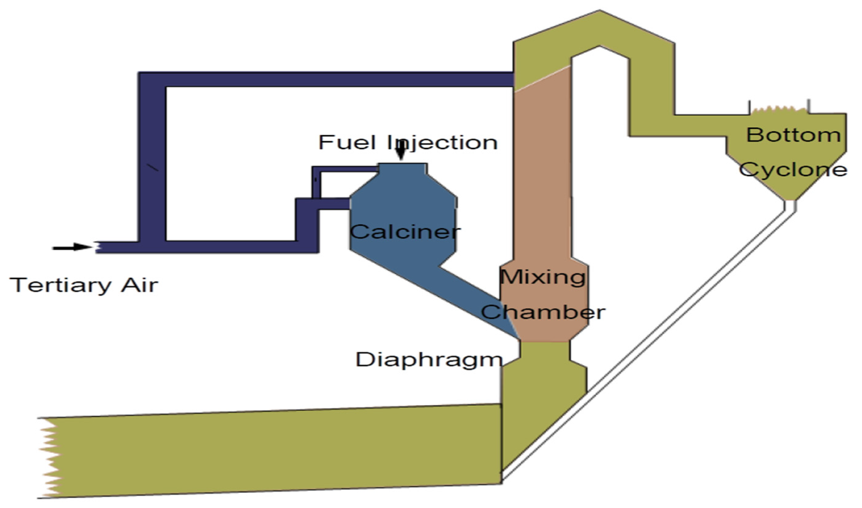
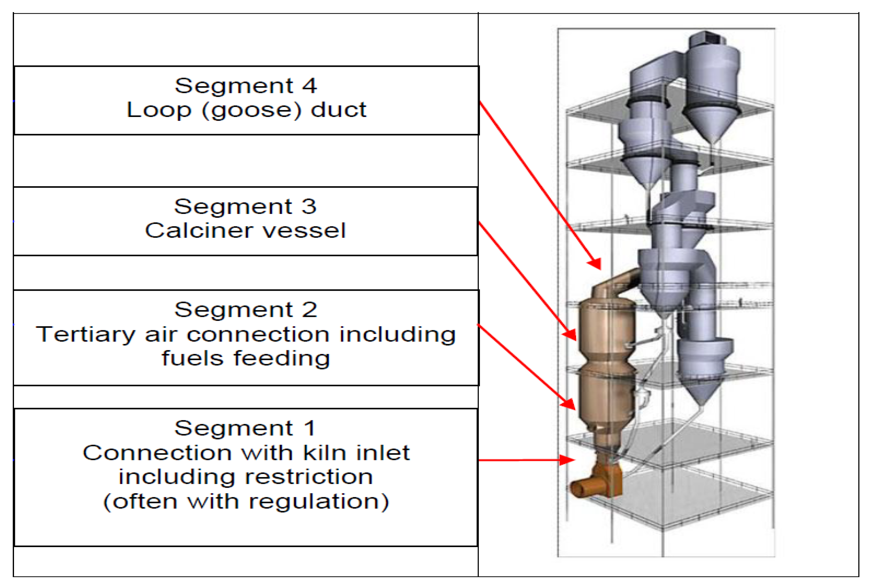
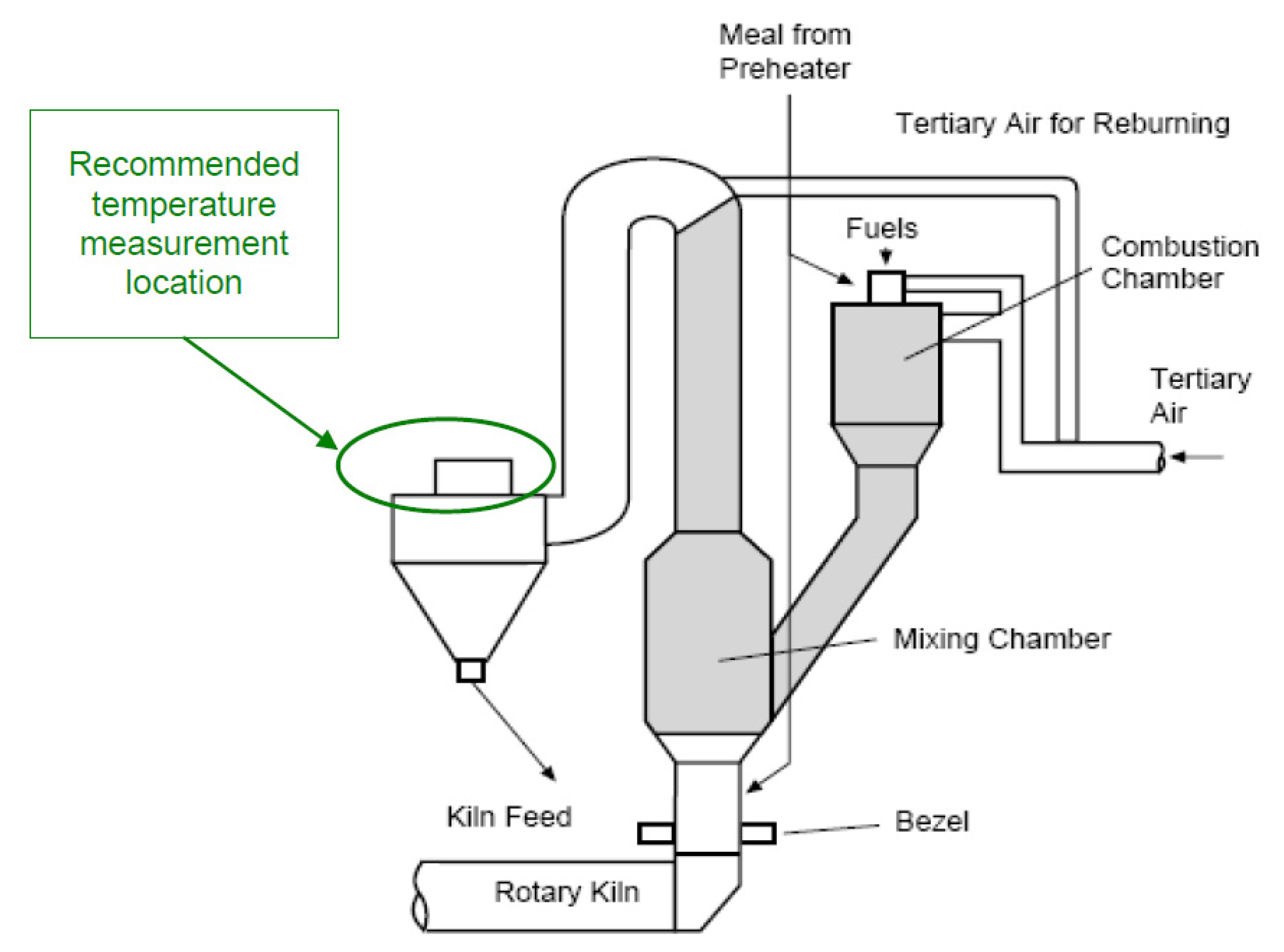
2.1. In-Line Calciner (Il-Calciner)

This kind of calciner is often constructed as a large vessel that is situated above the kiln inlet area (FLS type).
Other designs, referred to as tube calciners, have expanded riser ducts (KHD, Technip, Polysius).
The interior volumes of calciners have increased over the years due to the requirement of being able to burn alternative fuels. Most products currently available on the market are comparable to one another. A calciner consists of a vessel (Figure 1 and Figure 3) that is either in front of or behind the preheater tower and terminates in a duct known as a loop (goose). At the top of the preheater tower, this duct frequently turns and descends into the bottom cyclones.
Meal splitting is a frequently used solution in which meal is diverted from some of the cyclones above the bottom-most layer. This portion of the meal is placed higher in the calciner body, a little bit away from the fuel feeding area. Even though the amount of meal used in the calcination process is less than the amount of fuel delivered into the calciner, the temperature of the local gas rises, creating a so-called hot spot. To prevent any red streaks on the shell, particularly in tube calciner types, the amount of diverted fuel must be tightly regulated [16,17].
The simplest options are always the best. Some manufacturers’ rotatable diverters, which can potentially split in three directions, are visible. We must consider that such a design exposes the mechanisms to an atmosphere that can be quite hot and occasionally dusty. As a result, maintaining such a unit is both expensive and complicated. Any shared meal demands appropriate room (height).
Typically, fuel is delivered into the bottom portion of the calciner close to or at the location where the tertiary air is attached. The choice of provider is related to the variety of solutions. However, basic concepts should always be considered, regardless of the specifics. It is better to ignite with "pure" air than with an air and gas mixture. The better the combustion, the higher the temperature. Previous research has verified the above statements [18,19]: temperature progression over the entire gas channel must be used to monitor calciner functioning [20].
Unexpectedly, the majority of calciners have few thermocouples inserted before the gas enters the bottom cyclone. In accordance with the principles of meal splitting, a few thermocouples may be installed between hot meal splitting at least twice, depending on the size of the vessel. The goal is to prevent localized refractories from overheating. According to the author, an extra two units should be added above the initial "limitation" in terms of the type of vessel calciner to monitor the development of the calcination and combustion processes. The principles of the control loop are largely concerned with temperature control implemented after the bottom cyclone and are not based on the placements of the thermocouples stated above [19].
Alternative fuel particles are often larger than primary fuel particles and require some drop time before burning out, so if feeding alternative fuels into ILC calciners is considered, we anticipate ample height for initial combustion. One of the biggest advantages that ILC calciners have is that if fuel remains unburned, it can fall into the kiln inlet [21].
The ILC type is the greatest option whenever we must choose calciners for new kiln lines for modernizing preheater kilns. The calciner capacity must be sufficient to offer at least 5 s of average gas retention duration, regardless of the fuel (mix) used. The hot meal is divided to create a hot zone. The loop duct can typically be installed up until the top cyclones of a modern preheater tower, providing the largest internal volume and retention duration. Round vessels are optimal for extending the lifespan of refractory materials and making installation easier [22].
There is no conclusive judgement as to whether tube calciners are superior to vessel ones. Both options have advantages and disadvantages. When the tendering process is underway, suppliers from East Asian countries will likely offer a vessel solution, leaving buyers with little choice [23].

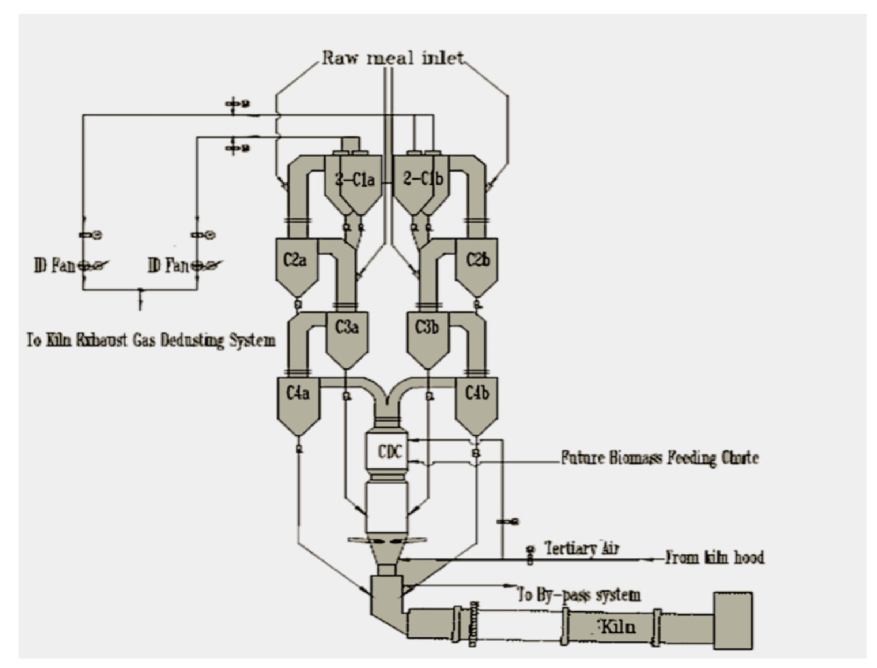
2.2. CDC (Chengdu Design Calciner)-CALCINER

The Chengdu Design Calciner is an in-line calciner; this type of calciner is usually designed as a big vessel located above the kiln inlet area. On the other hand, as the designs of so-called tube calciners show extended riser ducts, they have different working principles [24].
Over the years of calciner development, the necessity of burning alternative fuels resulted in increasing the internal volume of the calciner. A calciner consists of the vessel located in front or behind the preheater tower that ends in the so-called loop (goose) duct. This duct makes turns very often at the top of preheater tower and lowers onto the bottom cyclones [25].
ILC calciners, (Chengdu Design Calciner) usually contain the following parts: loop (goose) duct and calciner vessel. In-line calciners are suitable for firing both traditional and alternate fuels. Additionally, operation is easy, with single entry locations for both calciner fuel and tertiary air (Figure 4).
The ratio of firing in the calciner is 60% of the total, which represents 2.1 tph of CNS, while achieving a calcination rate at the kiln inlet of 95%, meeting the objective. For build-up and chemistry, there is an allowable kiln gas bypass of 10% that exists to help in the case of pre-calciner blockage. However, this was not an issue in our co-grinding test.
Preheater optimization as well as calciner optimization: The core of the pyro process of each modern cement kiln is the preheater. Most substantial thermo-chemical reactions of the cement process occur in the riser ducts and the calciner, as well as the sintering zone of the kiln. Preheaters are considered core equipment for modern kilns in terms of improving CDC combustion (see Figure 5).
This type of calciner is easy to operate, reliable, and has the lowest NOx emissions, thanks to our unique high temperature reduction zone. CO emissions are low too because our mid-calciner notch and specially designed exit duct provide superior mixing and combustion, as shown in Figure 5.

2.3. Tertiary Air Ducts

Basic items that describe tertiary air ducts [21]:
  • Shape and route;
  • Air velocity;
  • Splitting of tertiary air, also for low NOx purposes;
  • Process measurement.

2.3.1. Shape and Route

Calciners use a separate duct known as the tertiary air duct to collect the necessary air for burning. Typically, a TAD is linked to the clinker cooler through a separate outlet via the kiln hood. The kiln’s capacity can occasionally affect the connection point on the cooler side of the grate. Since kiln hood sizes are growing to enormous proportions and refractories may not be able to sustain the mechanical stress, it is quite feasible to link larger kilns with grate coolers rather than kiln hoods. From a process standpoint, connection to the kiln hood produces virtually identical secondary and tertiary air temperatures, whereas connection to the clinker cooler produces higher secondary and slightly lower tertiary air temperatures [26].
The tertiary air duct’s shape must be circular. Although this might seem strange, the solutions that contradict this claim only do so slightly. It is necessary for the duct to be horizontal or as close to horizontal as feasible. If the kiln hood and calciner levels consistently change significantly, this is challenging to accomplish. If there is no combustion chamber, we typically see a modest slope along the entire length of the duct or a severe inclination at the beginning that becomes virtually flat afterwards. One must keep in mind that all inclinations cause dust to settle internally. This implies the possibility for dust to slip into the cooler or kiln hood under conditions of a drop in pressure and insufficient air velocity [27].
Calciners with combustion chambers (CC) must contend with significant height discrepancies. To provide a path to the CC, some vendors are installing flat TA ducts and 90° turning points. The elbow is a prime location for dust to collect and can totally obstruct airflow. Thanks to open double gates at the bottom of the TA duct, suppliers have once more discovered a way to stop this problem by routinely removing dust [23].
In subsequent steps, the dust is released into a container or, in some cases, returned (by gravity) to the kiln input area. We must keep in mind that any clinker dust returning to the kiln’s intake causes heat consumption losses and could affect clinker formation [27].

2.3.2. Air Velocity

Internal air velocity is a crucial component of TA duct design. Without a doubt, air must move quickly enough to prevent large amounts of clinker particles from settling in the duct. When air velocity is low, the amount of dust can occasionally be so great that the support for the TA duct cannot sustain any more weight. To account for the duct becoming filled with clinker, an additional load must be included during tertiary air design [28].
As a rule of thumb, the gas velocity in the kiln inlet/riser restriction area should be comparable to the air velocity in the TA duct. However, it must be noted that any elbows, splits, or the presence of the combustion chamber may produce more drops in pressure and prevent air from moving down the TA duct, causing the kiln to operate incorrectly, even failing to operate at its designed capacity. Although this is a widely acknowledged problem, leading to the requirement that air velocity be greater than 25 m/s, some vendors provide air velocity values greater than 35 m/s [29].

2.3.3. Split of Tertiary Air

Some ILC suppliers separate secondary air into two (2) sections, while others only maintain one link to the calciner body. When connecting a somewhat large vessel and anticipating proper combustion, two connection points with a 50/50 air split are obviously preferable to one [30].
If the secondary air duct is situated at the far end of the calciner body and not above the kiln tube, the only way to regulate the airflow to the farther point is by opening the damper (gate). However, this creates a need for the damper to be operational and for additional maintenance [31].
Some tertiary air ducts are linked perpendicularly to the calciner body, while others are tangentially attached depending on the supplier’s design and experience with calciners. It must also be emphasized that the final connection shape or size may depend on the chosen supplier, so forcing the calciner provider to change the connection is not advised. Many suppliers supply a system in which a portion of the air is sent above via a so-called low NOx duct instead of entering the main calciner combustion process [32].

2.3.4. Process Measurement

At least one pressure transmitter and one temperature transmitter must be put near to the kiln hood region in the tertiary air duct. When TA ducts are divided, each duct split requires its own pressure transmitter [30].

2.4. Tertiary Air Dampers

By means of a tertiary air duct, combustion air (oxygen) is delivered to the calciner. The optimal kiln restriction area and tertiary air duct designs should provide the least amount of resistance while providing efficient air delivery for the calciner and kiln from the grate cooler. This means that if a kiln operates at design capacity, any damper must be completely open or removed [33].
However, in most kilns, air delivery must be regulated. This is related to many issues; the most common are [34]:
The starting area of the kiln operating at low output due to whatever reason;
Much greater coating in the kiln and the riser (restriction) area;
Operating with significantly different raw materials and fuels;
The fuel split between the kiln and calciner is different than originally assumed;
Design mistakes.
The primary function of regulating the air split between the kiln and the calciner is provided by tertiary air dampers (gates, flaps). Indication of proper air delivery (combustion) is given by gas analyzers, one installed in the kiln inlet and the other installed, most optimally, at the exit from the bottom cyclone. If, during prolonged operation, one notices that, despite the tertiary air opening being fully open, the kiln oxygen readings are high and the ID fan speed cannot be decreased, one can conclude that the riser duct and/or kiln are providing insufficient restriction. If a riser limitation is regulated, it should be closed; if not, consider changing the restriction area during the subsequent kiln stop. The coating that forms in the riser duct also “regulates” air split, so any modifications to fuels or raw materials must be carefully considered [35].
Clinker dust is present in tertiary air, which frequently has a temperature above 900 degrees Celsius. This air temperature value is undoubtedly greater because of the superior cooler recuperation process, which is always the greatest for calciner combustion. Although dust is always present when a kiln is operating, the amount of dust might vary depending on how the clinkering process is managed and whether the duct has a settling chamber. The lifespan of tertiary air dampers is significantly impacted by both high temperature and dust volume [36].
Concrete (refractory) on a steel frame or steel alone are the two most popular applications of damper design. The steel and refractory materials must be able to survive high temperatures and wear for at least one full production cycle. Due to the intricacy of their design and production, shut-off gates have substantially higher expectations in terms of lifetime [37].
We can distinguish the following tertiary air regulators [38]:
(a)
Butterfly dampers (and poppet valves for small quaternary air ducts);
(b)
Shut-off (regulated) gates.
Based on some review papers [36,38], it is not easy to choose a damper. Both types have their own problems in terms of lifetime and operation.

2.4.1. Butterfly Dampers

This type of damper is constantly present inside the duct, produces a certain drop despite having a 100% opening, and is completely exposed to air and clinker dust throughout all parts of its 100% operation. Typically, resistant steel is used, with the placement of a somewhat thin refractory castable layer (on anchors). The number of shafts depends on the size of the duct [39].
Each shaft must have an open core through which cooling air should be continuously blown from ventilators. This is to keep the shafts from bending and keep the valve in working order. To prevent any potential health and safety hazards, the cooling air outlet must be directed away from the platform area [40].
The area next to tertiary air damper should be equipped with a properly sized inspection door. The construction of the damper should allow for the quick replacement of each blade or drive arm.
These dampers are frequently seen in solutions that include a combustion chamber. They have a straightforward construction and allow for quick shaft and blade replacement. Typically, they only have a single production campaign that happens rather frequently. If the shaft is not deformed, these dampers operate consistently (until they are worn out) [34].
Such damper sets must be maintained as wear parts and be always available.

2.4.2. Shut-Off Gates

In tertiary air ducts, controlling air flow by raising or lowering the gate is a frequent approach. A gate is often constructed from a refractory concrete block mounted on a steel frame. Heat-resistant anchors are used to reinforce refractory concrete. The thickness is determined by the supplier’s design, although it cannot be less than 150 mm. A gate can only move vertically [41].
The gate is typically completely open while it is in operation, preventing constant exposure to hot air and clinker particles. The still frame on the side, if there is one, is exposed to dust if regulation is necessary, and an interior position is taken. Another frame (slide) holds the gate on both sides to maintain straight movement [17].
This type of gate always requires vertical movement such that the lifting mechanism has a certain amount of space above the gate. There must also be an access platform for the above-located drive unit (and counterweight) [34].
In most cases, these gates are located next to the preheater tower, and the tower main structure can be used for maintenance purposes. Some suppliers place the gate next to the grate closer to the grate cooler. This location has one disadvantage: the gate is placed on an almost area, so maintenance requires the use of a mobile crane and more platforms and staircases to reach each section [42].
Additionally, this type of gate is quite heavy and requires overhead crane access and logistics in case of replacement or serious repair. The replacement of such a gate is usually longer and more expensive than that for a butterfly gate (crane, scaffolding).
Some suppliers offer shut-off gates that are equipped with forced cooling systems. Fans are connected to specially designed “internal shaft” to improve the lifetime of the base frame anchors and refractory. Such a solution makes the whole system more complicated and heavier [43].

2.4.3. Regulated Riser Restrictions

The restriction area can be defined as the place between the kiln inlet housing and the calciner vessel connection (Figure 5a). This area usually has the highest gas velocity in the whole kiln and preheater tower. Pressure drops created here allow for splitting between kiln- and calciner-recuperated grate cooler air. The size of this area is usually fixed in a standard ILC calciner. Very often, this same place is used to compensate for thermal expansion [44].
Some calciner solutions, however, are equipped with regulated restriction areas. We see such designs mainly when the combustion chamber is present. The presence of a combustion chamber certainly generates a greater pressure drop than a calciner standard solution. Moreover, combustion chamber design has a certain complexity, and with changing operating conditions, coating can create greater pressure drops than anticipated [45]. A greater pressure drop means less air going through the tertiary air duct, which leads to worse burning conditions in the kiln (over-drafting, overheating). To compensate for this, some suppliers (e.g., Technip, FLS) have provided regulated restriction solutions.
Regulated restriction mainly consists of several refractory blocks that are moveable. The open position for regulated restriction means all blocks are fully out of the restriction area. The closed position means all blocks are fully inside. However, there is still enough space for kiln gas to pass through the closed position. Depending on kiln size, there are usually two to four blocks located on two sides of the restriction. The blocks are generally driven by electric motors, but very often by hydraulic units as well [46].
Restriction blocks are exposed to high temperatures and many are exposed to the aggressive chemistry of the kiln inlet area. Concrete (refractory) blocks are not always able to withstand such conditions across the entire production line [47].
To assure functionality, if needed, plant operators usually have certain routines to close and open blocks (in sequence). Any build-up on the blocks is removed and the driving system us tested. The usual routine is to close and open all blocks once per shift or day.
Though moveable elements require sealing, in such an area, the sealing is not perfect, and false air or meal dust can pass through [48].
Our experience with a moveable restriction (orifice) shows that its necessity and functionality are highly questionable. Complicated and requiring expensive maintenance, the hydraulic driving systems make the entire installation not very economical.
If, by chance, the restriction area is limited and this is discovered via long-term operation with certain block positions for desired kiln output, then one can decide to remove blocks and create a fixed restriction instead with the required dimensions. In fact, many plants do this soon or later after kiln start-up [49].

2.5. Calciner Burners

Fuel needs a mechanism to be fed into the calciner body, regardless of whether it is primary fuel (coal, natural gas, or oil) or alternative fuel [50].
As the end point of fuel pneumatic conveyance, simple pipes are frequently used to feed solid primary fuels (such as coal and pet-coke). They increase the amount of air available for combustion while decreasing the need for tertiary air [51]. However, certain materials have been used to produce calciner burners that have the same air control layout as the primary kiln burner. Axial, radial, and even central air are all available. Even though the burner’s size is reduced, the amount of this air is substantial, which further reduces the heat that is recovered from the grate cooler [50,51].
If supplied to a calciner, alternative fuels are frequently brought into the system by gravity and mechanical means. They are fed either by a separate chute or the calciner burner’s main piping.
If liquid fuel is utilized, it is pumped into the calciner using high-pressure pumps and nozzles, occasionally with the help of atomizing air. They can be positioned inside the burner pipe or spread out around the body of the calciner (similar to a kiln burner).
Natural gas feeding is frequently divided into several little pipes and connected to the calciner body at various locations throughout. Sometimes, a burner solution identical to or close to the primary burner design is used to feed natural gas [52].

2.5.1. Number of Burners

A traditional design would have (one) burner, (one) tertiary air inlet, and (one) hot meal pipe. The fuel feed is divided according to the most suitable kiln operations by each provider. One must keep in mind that a good fuel split (for example, for coal) can only be achieved if there are two independent fuel dosing units [53].
Though the idea is that the primary fuel simply separates on the air–fuel stream just before it reaches the calciner body, this is very unlikely. This type of split cannot guarantee that the required amount of fuel will be present at the dosing site. One dosing (weighing) instrument can be used in some calciner systems in as many as four coal feeding locations [54].
The number of burners is a very intricate issue that is connected to the placement of the burners in relation to the secondary air and hot meal connections.
Following the supplier’s design up until the kiln line is taken over is advised before attempting to discover a better fuel split in relation to the particular circumstances of the process [55,56].

2.5.2. Location of Burners

This case is once again a challenging one. It has been established that adding extra oxygen to the fuel mixture improves combustion. Thus, the best combustion occurs when hot tertiary air carried by a quaternary air duct reaches the burner’s position at the top of the combustion chamber [57]. For good primary fuels, this is true.
Standard ILC calciners lack a combustion chamber; the body’s average oxygen content is between 8 and 10%. Any energy from combustion that is present in the calciner body is promptly consumed by meal, thus limiting access to the required oxygen [58].
Most known solutions, according to the authors, adhere to the following rules [59]:
The burner is situated at the point where secondary air enters the body of the cooker;
“Pure” air ignition;
The hot meal is situated above or to the side of this point;
To reduce kiln NOx, a portion of fuel is inserted in the kiln inlet (riser).
To prevent any refractory overheating on the opposite side of the burner position, tube calciners further restrict the height difference between the burner and hot meal to the range of 0.5 (half) to 1 (one) meter (KHD 1.5–2 m) above the burner [60].
In general, the location, split, usage of additional primary air, and overall economics of the clinkering process must be determined in conjunction with the supplier’s design, operational experience, and CFD simulations [61].

2.5.3. Mono-Channel and Gravity-Fed Burners

Most typically, this kind of solution is used to feed calciner fuel, and burners are not even discussed. We recently connected a steel pipe to the calciner body, which is where primary fuel is discharged. This best solution maximizes the usage of hot air from the grate cooler while introducing the lowest primary (cold) air into the calciner [62].
If such a pipe is to be transferred to another location but is constrained by an earlier fuel–air stream split, simplicity also pays off. It can be quickly replaced if there is any wear. When it is not directly exposed to high temperatures, it usually needs no refractory.
The pipe must always be attached to the body or TA duct at a specific angle; the exact angle varies on the supplier’s particular solution.
If a vertically positioned burner is utilized with a combustion chamber, the major vortex produced by the secondary air entrance is opposite the burner’s tangential coal connection and kind of nozzle exit. This enhances the fuel’s mixing with the incoming hot quaternary air [63].
A small amount of primary air, albeit with slow air speed, has been introduced by some suppliers to the fuel input [64]. This type of burner setup applies to when coal is put into the Technip combustion chamber. Below is an illustration of one such solution. This specific illustration demonstrates how primary air is also sent in part to the coal duct.

2.5.4. Multi-Channel High-Momentum Calciner Burners

Some calciners are equipped with full air control burners with the same design as main kiln burners [65]. A full burner solution was chosen for one project where 100% natural gas was used and a combustion chamber was installed. Many previous natural gas feeding solutions to the calciner body or to a combustion chamber were based on multi-feeding point solutions. Natural gas is a rather difficult fuel to burn, especially if oxygen availability is reduced, similarly to in the calciner [66].

2.6. Calciner Process Control

Fuel, Calcination, and Control Loops

Regardless of the type of calciner (ILC, SLC, CDC, etc.), calciner fuel control should always adhere to the same fundamental guidelines. The obvious ones are a steady control mass flow rate from the fuel dosing system and good fuel homogenization to supply stable, quality fuel to the calciner(s) [67].
The capacity to regulate the fuel rate in a way that produces a consistent level of hot meal calcination is essential for successful calciner operation. The calciner exit gas temperature has proven to be the most accurate indicator of hot meal calcination and is thus advised as the process variable for controlling calciner fuel rate because there is currently no technology available for real-time continuous measurement of hot meal calcination degree [68].
The most common methods for fuel rate control to the calciner are:
Manual setpoint control;
PID closed-loop control;
Fuzzy logic (e.g., fuzzy logic expert system);
A “custom” calciner fuel controller.
Manual setpoint control (open-loop control (OLC)) is the lowest level of sophistication and the least recommendable solution of the list above. Manual setpoint control relies on the kiln operator’s constant attention and instinct to make the proper amplitude setpoint adjustments and with the correct timing according to the process changes to maintain stable temperature control. While some kiln operators can perform this task extraordinarily well for certain periods of time, the average result over the long term will always be of greater standard deviation from the target temperature than optimized computer-controlled fuel regulation [69].
PID closed-loop control (CLC) uses standard proportional (P), integral (I) and derivative (D) algorithms to automatically calculate the controller’s output from 0 to 100%, which is scaled to match each plant’s individual control variable (fuel rate) based on the PID controllers’ settings and the difference between the process variable (actual temperature) and temperature setpoint (target) [70,71].
The proportional control mode produces a change in the controller output proportional to the error signal (difference between actual temperature and set-point);
The integral control mode changes the output of the controller by an amount proportional to the integral of the error signal;
The derivative control mode changes the output of the controller proportionally to the rate of change of the error signal. Practically, derivative control is never used alone because the derivative mode only contributes to the controller output while the error is changing;
The proportional–integral control mode is the combination of proportional control and integral control to provide an automatic reset action that eliminates the proportional offset. The PI mode provides the reset action by constantly changing the controller output until the error is reduced to zero. This is the most common and practical CLC controller mode for cement industry applications. (i.e., derivative setting = 0);
The proportional–derivative control mode is the combination of proportional control and derivative control to reduce the tendency for oscillations and allow a higher proportional setting. The addition of derivative control provides good anticipation of the future error signal and therefore is useful for controlling applications with sudden load changes that produce excessive errors;
The proportional–integral–derivative control mode is a combination of all three individual control modes. The PID control mode is used on processes with sudden large load changes when one or two mode control methods are not capable of keeping the error within acceptable limits. The derivative mode produces an anticipatory action that reduces the maximum error produced by sudden load changes. The integral mode provides a reset action that eliminates the offset coming from the proportional mode.
Fuzzy logic controllers (expert systems) uses computer programming language and reasoning principles to attempt to simulate the way humans think and solve problems. A computer’s way of thinking is binary or “black and white” or “on or off”, but humans think in many shades of gray. However, humans can continuously evaluate many shades of gray to produce decisive actions despite somewhat vague (or fuzzy) knowledge of actual conditions [69,72,73].
Fuzzy logic can be very time-consuming to design, requires the programmer to have extensive knowledge of the process, and usually requires substantial fine-tuning and a significant number of process measurements that are accurate and have reliable uptime. For these reasons, fuzzy logic controls are not as common as other types in the cement industry. However, the control potential of fuzzy logic or fuzzy logic in combination with PID does exceed the typical control possibilities achievable by other controller types [72].
Custom calciner fuel controllers are controllers that can take many different appearances, principles of operation, and design.
These custom controllers are based on the concept that the calciner exit temperature responds differently to a fuel rate change depending on if the calciner exit temperature is increasing or decreasing. If the temperature is decreasing, it typically requires a bigger increase in fuel and more time to stop the temperature fall and then turn it around to increase the value back up to the setpoint. Considering the opposite situation of when the temperature is increasing, the calciner exit temperature typically will stop increasing and start decreasing towards a setpoint much faster compared to a smaller fuel rate change. PID control does not distinguish between the direction in which the error is traveling away from the setpoint, only the absolute error, the integral of the error, and the rate of change of the error. The Union Bridge (UB) custom controller is designed to recognize if the calciner is increasing or decreasing in temperature and how fast, and then accordingly takes different actions based on these facts [69,72].

2.7. Active Setpoint

2.7.1. Calciner AF-Fuel/Coal Feed SP

The purple box provides the actual setpoint of calciner fuel. The unique advantage of this method that contributes to its success is that operators can type in a new setpoint at any time without deactivating the automatic controller if they see the need to make an adjustment [74]. An example might be that the operator just increased the kiln feed rate and wants to be proactive in adding some fuel to compensate for the expected temperature drop [75]. This feature gives operators the ease and feeling that they are always still in manual control, but with the added benefit of “auto-pilot” coming from the continuous watch of the controller.
Temp Change in Last 3 min is the rolling average of the calciner exit temperature change over the previous 3 min.

2.7.2. Setpoint Adjustment Based on Change in Temperature

  • Setpoint Adjustment Timer: user-defined frequency with which the controller makes a setpoint change (if necessary);
  • Elapsed Time: a timer that resets to zero, restarts, and triggers a setpoint change when the timer equals the setpoint adjustment timer;
  • H Limit: user-defined value for which if the temperature change in the last 3 min has exceeded (in this case 4 degrees), the controller triggers a fuel setpoint decrease (in this case a Decrement Value of 0.05 t/h AF-fuel);
  • HH Limit: user-defined value for which if the temperature change in the last 3 min has exceeded (in this case 13 degrees), the controller triggers a fuel setpoint decrease (in this case a Decrement Value of 0.17 t/h AF-fuel);
  • L Limit: user-defined value for which if the temperature change in the last 3 min has exceeded in the negative direction (in this case 2 degrees), the controller triggers a fuel setpoint increase (in this case an Increment Value of 0.08 t/h AF-fuel l);
  • LL Limit: user-defined value for which if the temperature change in last 3 min has exceeded in the negative direction (in this case 8 degrees), the controller triggers a fuel setpoint increase (in this case an Increment Value of 0.20 t/h AF-fuel).

2.7.3. Setpoint Adjustment Based on Change in Temperature

  • Stg 5 Temp Max: Upper control limit temperature for calciner exit gas. Above this limit sets off a max temperature limit alarm and blocks output to increase the fuel setpoint;
  • Stg 5 Temp Min: Lower control limit temperature for calciner exit gas. Below this limit sets off a min temperature limit alarm and blocks output to decrease the fuel setpoint;
  • Stg 5 Temp: actual real-time calciner exit temperature;
  • Coal SP Max: user-defined input for maximum controller allowed setpoint to coal dosing system;
  • Coal SP Min: user-defined input for minimum controller allowed setpoint to coal dosing system.
The controller has numerous alarms and checks to ensure that the system operates within normal ranges and limits.
The temperature measurement location for calciner fuel control can have a big impact on the process of obtaining true calciner exit temperature and controller stability. Both points have considerable impact on items such as degree of calcination, build-up, and blockages, as well as if the operators tend to use automatic control loops or instead try to manage fuel manually [76].
The general location of the temperature measurement for calciner fuel control should be as far downstream (gas flow) as possible, but not in a location that could be influenced by meal from upstream (meal flow) cyclones [77]. The reason for this is to allow as much time for complete combustion of the calciner fuel and to obtain an as accurate “final combustion” temperature as possible, which influences the hot meal entering the kiln. In other words, just before, inside, or just after the bottom-stage cyclone are generally recommended locations for AF-Fuel control temperature measurement [78]. It is not recommended measure the temperature anywhere before the last tertiary air or meal from the preheater entry location, as these will both have significant influence on the final degree of hot meal calcination.
The specific location for fuel control temperature measurement is also important with regard to a successful and especially reliable measurement. Figure 6 and Figure 7 shows the top three recommended locations.

2.7.4. Cyclone Outlet

Pros:
  • Measures combustion results as far downstream as possible before the gas temperature is influenced by upstream meal;
  • Low abrasion since dust concentration in the gas is lower after the cyclones. Typically, good, safe access to cyclone roofs.
Cons:
  • Risk of meal dropout from above could give a falsely low calciner exit temperature and result in over-fueling the calciner;
  • Any combustion that might occur after meal classification does not contribute towards calcination but does influence fuel control.
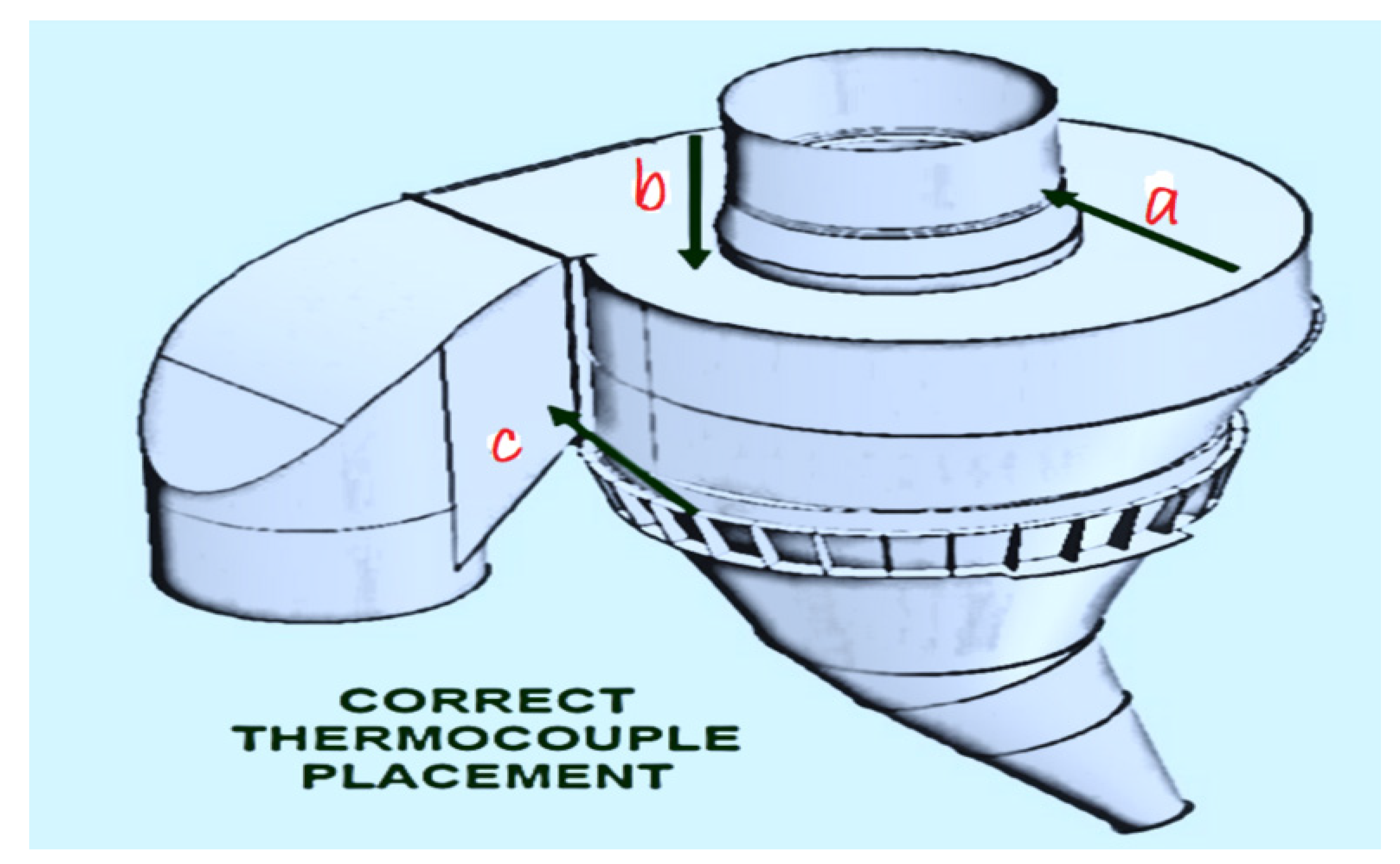
The thermocouple must be installed as close to the cyclone roof as safely possible, and measurement ports should be installed at equal heights above the cyclone roof to make manual temperature verifications of thermocouple values possible (Figure 7c).

2.7.5. Cyclone Roof

Pros:
  • Very accurate location for measurements of the last combustion that contributes towards calcination;
  • Low abrasion since dust concentration in the gas is already under the classification effect;
  • Typically, good, safe access to cyclone roofs.
Cons:
  • The risk of build-up on the cyclone’s roof could give a falsely low calciner exit temperature and result in the over-fueling of the calciner;
  • To best avoid thermocouple abrasion, it is important that the exact location is towards the inside radius, closer to the dip tube, and close to the end of the meal’s revolution around the cyclone (Figure 7b).

2.7.6. Cyclone Inlet

  • Very accurate location for measurements of the last combustion that contributes towards calcination;
  • Low abrasion since dust concentration in the gas is already under the classification effect of cyclone inlet geometry;
  • The risk of build-up on the cyclone inlet could give a falsely low calciner exit temperature and result in the over-fueling of the calciner;
  • Access to this area does not typically exist.
To best avoid thermocouple abrasion, it is important that the exact location is on the inside inlet wall and towards the bottom half of the inlet vertical opening (Figure 7).

2.8. Calcination Degree of Hot Meal

Each calciner must produce hot meal with a consistent level of calcination. Meal from the bottom of the cyclone must be sampled and tested to determine the degree of calcination. Some research papers advocate quick analytical techniques based on CO2 measurement since they are independent of meal chloride content, which can affect traditional lost on ignition (LOI) analysis [69,79].
We must keep in mind that sampled hot meal comprises not only “freshly calcined meal,” but also clinker and dust from the full calcination process, as well as fuel ash on occasion. The supplier’s kiln inlet design, gas velocity in the kiln, and other factors affect the amount of returning dust [80].
Because of this, the degree of calcination does not exhibit its genuine value but rather a perceived value that is higher than it should be based on the split of energy. Kiln dust has somewhat less of an impact on separate-line calciners, as not all kiln dust may be sent to the calciner string [81]. The proper calcination degree for a given kiln is calculated based on long-term observations of the kiln with the expected output using Equation (1). Kiln dimensions and maximum possible rotation speed are also taken under consideration. Dust circulation between the kiln and calciner might only be found based on long-term operations [82].
The target calcination degree (apparent) for most three-pier kilns is expected to be between 91% and 93% but not higher than 95%. Short two-pier kilns have a calcination degree around 95%. The pointed numbers refer to the standard fuel split between the kiln and the calciner, which is around 40/60 [83].
DoC   HM = ( LOI ( a ) 100     LOI ( a ) )     ( LOI ( b ) 100     LOI ( b ) ) ( LOI ( a ) 100     LOI ( a ) )
Equation (1): The calcination degree formula, where: a: kiln feed; b: hot meal [83,84].

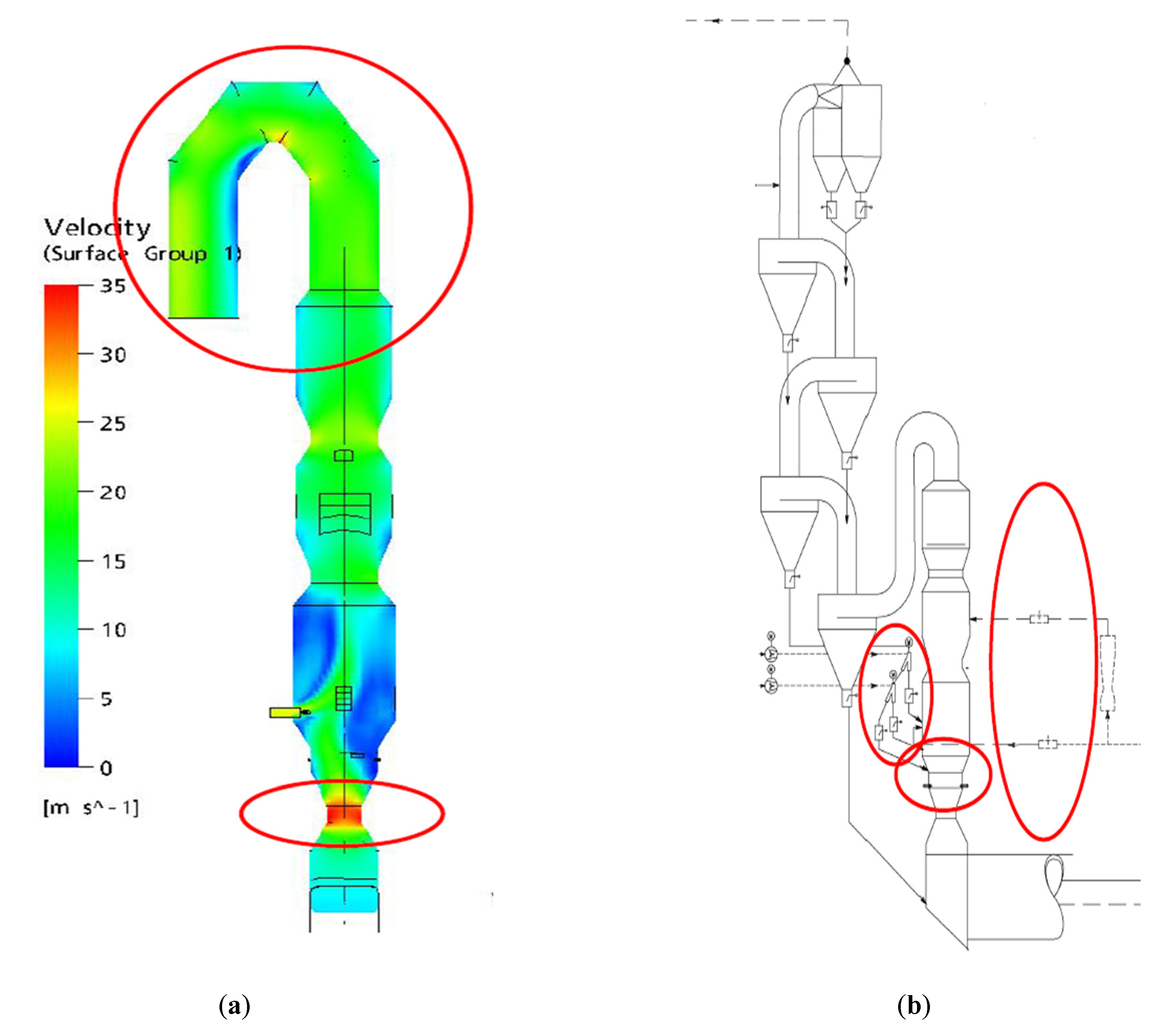
2.9. Computational Fluid Dynamics (CFD) Modeling for Calciner and Combustion

As a result of the ongoing increase in energy prices and other operational expenditures, all cement makers are required to adapt their operational processes to these problems. Additionally, the creation of an environmentally sustainable strategy to drive industrial growth has always been and remains the one major difficulty for cement producers. Manufacturers are motivated by this circumstance to look for various solutions and optimizations that can increase their level of competitiveness [84,85]. On the other hand, it is generally acknowledged that the cement business is technically extremely complicated, with several concurrently occurring time-dependent and interconnected processes [86].
Experienced plant engineers have always preferred more practical approaches than comprehensive mathematical modeling solutions since they were seen to be excessively complex [87]. Cement engineers, for instance, are often happy to choose the size of the calciner based on residence time criteria, which can be determined using a straightforward calculation including gas flow rate and ideal gas velocity [88]. This strategy, nevertheless, has several flaws that could be gravely misleading. The flow pattern can be affected by geometry (square or not square), aspect ratio (L/D), and even tertiary air orientation. Furthermore, fuel particles with significant shape irregularities, which are typically seen in alternative fuels, may follow distinct paths within the main gas stream [89].
The estimation of residence time, which regrettably cannot be encapsulated in a single formula, can undoubtedly be impacted by all these real-world physical events. Complicated problems can now be broken into smaller, more manageable ones thanks to advancements in digital technology, and these smaller, more manageable problems can then be solved using computational fluid dynamics (CFD). Such a development will undoubtedly encourage the use of CFD soon, which may eventually take the place of conventional methods and trial-and-error in optimization and design in the cement sector [90].
One of the subfields of fluid mechanics known as computational fluid dynamics (CFD) uses numerical techniques and algorithms to solve and analyze issues involving fluid flows. The mathematical model is created to closely resemble real-world occurrences around subjects of interest such as calciners, kilns, cyclones, etc. The countless computations needed to represent how fluids and gases interact with intricate fluid surfaces as well as how particles and dust move are then carried out by computers [91].
Numerous case studies, ranging from separation technology (cyclone and separator) to pyro-processing technology in the kiln and pre-calciner, illustrate the rapidly expanding interest in CFD applications in the cement sector. With the use of alternative fuels, interest in CFD or advanced mathematical models has grown dramatically, especially for pyro-processing. This is demonstrated in several pyro-processing-related publications from cement producers and cement technology providers, as well as academic and research institutions [92].
CFD-based analysis in pre-calciner operation has been used on an industrial scale to support several technological advancements, alterations, and modernizations.
The most notable actions within some research papers were started in the works/studies carried out in recent years, where the works resulted in successful calciner modification as well as comments and recommendations related to incomplete combustion in a hot-disc-equipped calciner. Additional actions have been carried out in a variety of applications, including the straightforward modification of the coal burner injection point [93].
Applications can also include challenging ones, such as the appraisal of a recently constructed natural-gas-fired pre-calciner that was developed by the Chinese company SINOMA.
Similar work has also been carried out at Holcim, where CFD has been heavily utilized in the optimization of the world’s largest biomass project, involving 400,000 tons annually, which replaces 65% of thermal consumption by burning rice husks and kernel palm shells in an 8000 tpd plant in Cilacap, Indonesia [94]. Holcim has used CFD to identify the best burner and calciner configurations as well as how to modify the kiln hood to avoid excessive CO and build-up in the kiln after switching fuels [95].
The major benefit of employing CFD is that it can be used to forecast how any optimization efforts would affect the processes inside the concerned equipment domains. Before any alterations are carried out in a real project, proper CFD simulations can vividly visualize and mimic the changes in process behaviors caused by any modifications or changes [96]. Since we previously dealt with invisible processes inside a vessel, this is especially significant [97]. Engineers can better comprehend phenomena and process behaviors that may occur inside the vessel because of CFD’s visualization power, which no other technique can match. With all these features, this technique is strong. In addition to being a tool for optimization, it also aids in determining the risk associated with any adjustments or optimization attempts. This method can also be used to assess whether a supplier’s supply of new technology is indeed good and offers a good value for the money. This is especially important given that suppliers frequently claim that their product is the best, and cement makers frequently hesitate to decline an offer out of ignorance or a lack of appropriate tools for evaluating it.
The biggest challenge in implementing this potent technique is the need for well-trained CFD engineers to representatively build and select the mathematical model of the relevant physical phenomena included in each case of simulation. This powerful technique does require several simplifications as well as limitations on some models’ validity, which is common in mathematical modeling. Additionally, the engineers need to be able to correctly understand the findings of the CFD simulations. However, quick advancements in commercial CFD software may help to partially overcome this challenge. Today’s commercially accessible software make it easy to employ CFD. Users no longer need to perform programming tasks, such as specifying AF-Fuel combustion, because the majority of CFD software already includes this functionality [89]. This development undoubtedly gives more practical engineers (in the cement industry) greater flexibility to use CFD for a wide range of applications and interests, even though the fundamental knowledge of combustion and other thermo-fluid science is still indispensable and important for choosing mathematical models and interpreting the results.
For the existing DOPOL pre-calciner, one interesting result was shown in CFD simulation results, where it appears that both meal and fuel particles (pet-coke) segregated inside the pre-calciner [98]. In this case, the asymmetric arrangement of tertiary air likely caused more of a certain size of the meal and pet-coke particles to be found in one side of the pre-calciner than the other. This would certainly create an unbalanced load for calcination and combustion, which may be reflected in a relatively low degree of calcination and poor combustion (CO ~ 0.35% or 1000 mg/m3).
CFD simulations have also been used to study the combustion behavior of three different types of fuels: pet coke, RDF (refuse-derived fuel), and TDF (tire-derived fuel).
It is clearly depicted that TDF requires more time for complete burnout. In TDF lines, the lines marked in yellow indicate a longer devolatilization stage compared to those for pet coke and RDF. The simulations clearly suggest that the residence time is not enough for TDF to reach a complete burnout level, since the TDF lines are still marked with red as the particles leave the pre-calciner (at the outlet) [89]. Meanwhile, both pet coke and RDF are shown to highly unbalance burnout at the outlet, which is strongly linked with segregation phenomena in the pre-calciner.
CFD remains an expert user’s tool, where both the CFD software and modeling engineer must be qualified to solve the problem of interest.

2.10. Minimize the Risk of Build-Up and Ring Formations in Preheater

2.10.1. Proper Balance of Sulfur and Alkalis

It is crucial to have alkalis and sulfur that are appropriately balanced. A well-known formula can be applied for this evaluation. When determining the sulfur–alkali ratio using this formula, the right period and regular operation must be kept in mind. Otherwise, incorrect findings may be obtained. All analyses resulting from excessive or insufficient burnings, irregular kiln feed rates, and irregular fuel feed mixtures must be eliminated from the calculation [99].
Use alkali–sulfur material corrections to balance the system. Bear in mind that in the case that the bypass is operated, some alkali material is removed, which can lead to an imbalance. Bypass dust handling should be considered during evaluation or measurement of volatiles and mass balance creation together with inputs (raw materials and fuels). An excess of alkali or sulfur leads to the undesirable formation of preheater build-up or, alternatively, kiln rings. Calculating the balance of volatiles is a starting point to eliminate the formation of build-up and rings during kiln operation. Ideally, the SO3 content in the clinker must be below 1.5% to avoid dusty clinker, which can reduce the recuperation efficiency of clinker cooler. Sulfur volatility should be monitored and should always be below 70% [84].

2.10.2. Proper Control of Chlorides

With a higher substitution of high-chloride alternative fuels, it is unavoidable to install and operate a chloride bypass. It is recommended to use it if the total input of chloride is higher than 0.3–0.4 kg of Cl/t of clinker. Nevertheless, the exact number depends on other factors too—especially sulfur volatility, tower cleaning tools, and the quality of their use—and in some cases, chloride inputs without operation of the bypass can be even higher [100].
In case there is no other source of chlorides, 0.3–0.4 kg of Cl/t of clinker corresponds to approximately 50% alternative fuel with an average chloride content of 0.5% and a net heat value (NHV) of 22–23 GJ/t [101]. In general, preheater kilns and calciner kilns can be operated safely (without kiln stoppage due to frequent cyclone blockage) by controlling the chloride in hot meal to below 1.0% and by controlling the SO3 in hot meal to below 5.0%. SO3 + 2Cl in hot meal should be calculated and monitored. The risk of cyclone blockage is increased in the case that this figure is higher than 3.5. In addition, maintaining high oxygen at the kiln inlet to decrease SO3 in the hot meal can minimize the risk of kiln stoppage due to cyclone blockage [100].

2.10.3. Proper and Well-Maintained Tower Cleaning Tools

Good maintenance is essential: the fast action of pilot valves, fast pressure release, tightness without air leakages, good quality of compressed air, and periodic operational checks for air cannons are required [102].
Air cannons with flexible control systems have the properties of grouping, time sequence adjustments, and time delays specific to certain areas. The Cardox system employs high-pressure CO2 (700–1200 pressures), is quick and very efficient, and can clean large areas and remove large lumps of coating with the requirement that all staff receive safety training, as the most perilous, medium- to high-pressure water cleaning requires regular training and the use of specialized safety equipment (high-temperature-resistant clothes) [103].

2.10.4. Moisture Input at Calciner Burner

Keep the fuel mix’s moisture levels low. The total moisture for a main burner should preferably be less than 20 kg H2O/ton of clinker (for example, clinker with 40 kg H2O/ton has a 400 °C lower flame temperature).
If there are no other ways to prevent high water input via the main burner fuels, think about ways to make the alternative fuels drier to prevent excessive specific water content in the main burner: AF quality selection, alternative supplies, low quality penalties for non-standard deliveries, etc. [104].

2.10.5. Ash Input at Main Burner

Avoid excessive fuel mix ash. The total ash for a main burner should ideally be below 30 kg ash/ton of clinker [105].

2.10.6. Booster Fuel

“Booster” fuel should ideally be alternative fuels: waste oils/solvents, or alternatively fossil, e.g., natural gas, heavy oil. Properly atomized liquid fuel spread into a calciner burner with a net heat value minimum of 27–28 GJ/t in the amount > 1–3% can help intensify and stabilize the flame (flame shortening) and help further increase total AF substitution. In such a case, it is even feasible to achieve very high solid fuel replacement rates (>95%) [100].

2.10.7. Fuel Mix Package in Calciner Burner [100]

  • Maintain a stable fuel mix package;
  • Avoid complexity in the fuel mix package to avoid a huge amount of fuel transport air at the main burner.

2.10.8. Oxygen Enrichment

Improve combustion under the oxygen-enriched primary air [100].
  • Typically used in the amount of 7–10 kg O2/MW;
  • Shortens the flame and fuels burnout;
  • Positive impact on sulfur volatilization;
  • Eliminates (at least partially) reducing conditions;
  • Fuel cost evaluation is also necessary in this case.

2.10.9. Variation in Inputs

Stability should be a standard for any kind of process; nevertheless, for high use of AF, it is even more essential. The process must be kept much more stable to allow for the feeding of lower-quality AF in comparison with fossil fuel combustion. This process needs more attention, cross-checks, and control of instrumentation to prevent its failure [102].
  • Stable feeding and weighing;
  • Fluctuation in kiln feed dosing ≤ 1.0% (10 min test);
  • Coefficient of variation for R90 micron of kiln feed ≤ 5.0%;
  • Fluctuation in traditional fuel dosing ≤ 1.0% (10 s test);
  • Coefficient of variation for R90 micron of traditional fuel ≤ 5.0%;
  • Stable clinker chemistry:
  • Short-term standard deviation of LSF ≤ 1.2 (daily basis);
  • Long-term standard deviation of LSF ≤ 1.0 (monthly basis);
  • Short-term standard deviation of silica ratio (SR) ≤ 0.04;
  • Short-term standard deviation of alumina ratio (AR) ≤ 0.04;
  • Standard deviation of free lime in clinker ≤ 0.2;
  • P2O5 ≤ 0.5.

2.10.10. Variation in Heat Input

Low heat input fluctuation is essential especially for main burner fuel mix. Fluctuations in calciner fuels are absorbed by proper control of the bottom-stage inlet/outlet temperature. The overall stability of heat flow is given by a combination of feeding accuracy and stability of the fuel mix average net heat value (NHV). The coefficients of variation for each part can be determined with the following formulas [102]:
  • Coefficient of variation (NHV) = standard deviation (NHV)/average (NHV) × 100%;
  • Coefficient of variation (weight) = standard deviation (fuel feeding)/average (fuel feed) × 100%.
Variations in fuel weighting should not be higher than 1.5%, while variations in fuel net heat value (NHV fluctuation) should be ideally below 3%. The overall variation in heat input is a multiplication of both numbers and should be less than 5%. In the case of more fuels fed into the kiln, we should analyze each fuel separately in addition to overall heat input variation. The overall heat input variation should be weighed as an average. High variation in one fuel input should not have great influence while its share in the heat input is much smaller than that of those with higher stability. The below example shows calculations for two fuels, but the same method should be applied to multifuel inputs.
In case we can keep the coefficient of variation for total heat input below the number mentioned above, extra excess air levels in the kiln and calciner are not required and have less negative impacts on specific heat consumption and clinker production after the maximizing of alternative fuels can be observed.
  • In case we have exceeded the previously mentioned limits, we can consider the following steps:
  • Ensure proper fuel weighting (provide good maintenance, right weighting equipment, proper weight device setting);
  • Provide proper fuel mixing (fuel proportioning, improve control of the fuel recipe);
  • Evaluate the use of new instrumentation tools to predict/supply information about incoming quality to the burner.
The NHV data set for fuels must include at least 24 results (on an hourly basis) per day to calculate the coefficient of variation (NHV). Many cement plants use alternate fuel for the main burner without having a complete understanding of how heat input varies. This is one of the variables that prevents the use of alternative fuel in the main burner from being maximized [100].

2.11. Kiln Burner and Use of Alternative Fuels

  • The use of satellite burners, when compared to burning via the main burner, cannot be stated to be a proven method based on the most recent information in cement technology. Alternative fuel delivery through satellite burners carries the danger of improper combustion, and some of the solid particles it delivers may fall into the clinker bed and affect the clinker’s quality [97];
  • The excessive burning-zone-specific heat input is caused by improper burning via satellite burners and/or main burners. This finding is based on a new kiln line in the Schelklingen facility, where firing solid alternative fuel via a satellite burner with incorrect POLFLAME burner combustion resulted in a more than 50% increase in heat input;
  • Alternative fuels must be injected through the main burner; satellite burners are merely an “option” [97].

2.11.1. Calciner Kiln Control

As a controlled parameter, use the NOx at the kiln inlet to reduce the possibility of meal flushing. Heat input via the main burner and the kiln ID-fan must be adjusted appropriately when NOx is being observed at the kiln intake beneath the target. When compared to kiln main drive current, employing NOx at the kiln entrance has the advantage of quicker control over kiln operation. A standard indicator for any kiln should be the main driving indications (amps, kW, etc.). Due to the short material retention time inside this type of kiln, NOx control as an early indicator is especially advised for calciner kilns [69].

2.11.2. Dimensions of Alternative Fuels

Proper fineness for alternative fuels (finer means better):
  • Light particles (foils, papers, thin 1D or 2D pieces) ≤ 40 mm;
  • Medium 2D weight particles (harder plastics) ≤ 15 mm (preferably < 10 mm);
  • Heavy or 3D particles (rubber chips, hard plastics) ≤ 10 mm (preferably < 5mm).
  • Avoid too-low average net heat values provided to main burners;
  • At least 21 GJ/t for AF replacement rate substitution of 0–65%;
  • At least 23 GJ/t for AF replacement rate of 65–90%;
  • The boundary depends on fuel type, as finer highly volatile fuels allow for operation with lower overall net heat value (animal meal/sewage sludge, liquid waste), while bigger moist particles demand higher burner average net heat value.

2.12. Calciner Kilns and Use of Alternative Fuels

Calciner kilns permit the use of significant quantities of inferior alternative fuels. When designing calciners, minimum temperature requirements relating to fuel quality must be considered. The fuel input inside the calciner should be at least 50% of the total heat input to the kiln system to achieve temperature requirements above limitations [103].
Stable calcination for hot meal enhances the overall stability of the kiln’s operation and raises the main burner’s air flow rate. Possessing effective control over the calciner’s exit temperature is essential for success [104].
To stabilize the calcination process, calciners should be outfitted with installations that can feed better-quality/finer fuel, which can also be an alternate fuel source, in addition to providing low-quality fuel. There are, hence, two calciner feeding installations needed.
The calciner must ensure that kiln gases are distributed evenly, have a modest oxygen surplus, and minimize CO emissions [105].
A well-constructed and managed calciner should be able to burn all the AF. Due to the shorter material retention time in the kiln, meal flushing (under burning) risk can be higher than in preheater kilns (even with high calcination degree). In some circumstances, the kiln must run with a material retention time of fewer than 20 min to maintain an adequate level of material filling and drive power. Therefore, operators must act more quickly to attain the NOx target at the kiln inlet. Based on the fuel mix package at the main burner, the target NOx at the kiln inlet must be modified. It should ideally fall between 1000 and 1500 ppm [103]. The same issues regarding fuel quality and stability of heat input from fuels, specific heat load in the burning zone of the kiln, and clinker cooler that are discussed in the preceding section apply to the calciner kiln as well. When using a complex fuel mix package at the main burner (more than two types of fuel), having a high percentage of primary air (>15%), having low secondary air (1000 °C), having poor combustion on the main burner and/or satellite burner, and having raw materials that are difficult to burn, it is difficult to achieve the ideal fuel split via the main burner (approximately 40%) [104].
The use of auxiliary units (reactors), such as Fire Bed Combustors (FBCs) or Step Combustors (SCs), plus efficient combustion in the main burner, should be taken into consideration to obtain the lowest specific fuel cost with the greatest amount of coarse alternative fuel [103]. Remember that the pneumatic portion of the transport line from the AFs to the main burner needs to be as short as possible (ideally, from the main burner platform), and that a straight transport line without any bends to the main burner is highly advised to reduce the amount of transport air and number of pulsation issues [105].
Due to their flexibility and efficiency in burning solid alternative fuels, in-line calciner kilns should be the default choice for any new kiln line project with a high alternative fuel utilization. Alternative fuel is not advised for kilns using separate-line calciners (SLCs) [105].

3. Methodology and Description

This study presents technical results on how AF-Fuel affects green industrial operation management [6]. The methodology for this case study is represented below and is similar to that described in [16]. A preliminary case study is presented on the substitution of coal with AF in a cement production plant in Togo. AF-Fuels affect the performance of plants due to their different characteristics compared to conventional fuels such as coal. Within the plant, two major injection points of AF-Fuel are available: at the kiln inlet ( segment one) and segment two. In terms of co-processing, the energy efficiency and performance of the CDC were evaluated as compared. Figure 3 describes the four main segments of an ILC calciner. This study concentrates on the performance of the plant in the two segments during AF-Fuel substitution.
The AF-Fuel was first injected into the kiln inlet. The fineness of the raw was %90 µm. In order to assess the performance, the following onsite parameters were measured: CO and O2. CO is an indication of incomplete combustion, while too little or too much O2 affects effective combustion of the fuel. During the substitution, various ratios of coal to AF were used to assess the performance of the plant under various substitution ratios. Finally, the quality of the clinker (final product) produced was assessed using XRF in the laboratory.

4. Results and Discussion

Table 1 shows the operation data and laboratory results of the CDC in the first feeding position. The raw meal is the material co-burned in the kiln and the lime saturation factor (LSF) is between 104 to 115. The silica module (SM) is about (2.36 to 2.5); the iron module (IM) is about (1.4 to 1.5); the fineness of the raw meal is about (7 to 10 µm); and alternative fuel feeding started at values from 0.85 t/h to 1.96 t/h.
The coal in the main burner (Coal Main b) was fed at values from 12.66 to 14Tt/h, while the coal in the pre-calciner (Coal prc) was fed at values from X to Y.
Table 2 shows the gas analyses, clinker analyses, and operational adjustments to keep the system stable. The pre-calciner gas analyses (Preca Gas Anal) consisted of O2 and CO%, with the same for kiln gas analyses (Kiln Gas Anal). The kiln operation parameters are as follows: inlet pressure (Mbar); kiln ampere (Amps); ID Fan parameter; damper opening percentage (Open%); and damper inlet pressure (Mbar).
The clinker quality analyses show the percentage of free-lime (F-CAO), the percentage of C3S, and the percentage of SO3.
Table 3 and Table 4 illustrate the same statement with different feeding positions of alternative fuels in a pyro system.
Figure 8 shows the impact of substitution on AF-Fuel injection points. In the original design of the CDC pre-calciner, the AF-Fuel was supposed to be injected next to the second tertiary air connection (low NOx reducing ducked) points on the same level. These positions were changed, with the first in the kiln inlet and the second moved to the same position as the meal and coal injections. In doing so, coal and AF-Fuel combustion was delayed for two reasons. Firstly, meal and released CO2 would act as the inert in the combustion process; hence, the flammability limit of burning coal and AF-Fuel volatiles was severely compromised, where combustion could only be stabilized in an oxygen-rich environment (requiring more excess air).
The second is associated with a slower/reduced combustion rate because of low temperatures in a meal-quenched zone. Such things finally motivated the plant to move the AF-Fuel injection points to segment three or the calciner vessel from their two previous positions. The result obtained from AF-Fuel entering from its second position (as illustrated in Figure 8) indicates that the AF-Fuel particles are partially combusted in the first 5–7 m of the initial injection points, leaving about 60% of uncombusted AF-Fuel to be combusted in the remaining length of kiln. This can also be seen by comparing the distance/length of the pre-calciner occupied by red particles, which are associated with unburnt fuel.
By moving the coal injection points, the CO levels at the lowest cyclone and kiln inlet were easily maintained at their maxima, 0.8% at the lower cyclone and 0.74% at the kiln inlet (0.5% was common in the modern kiln). This improvement is partially responsible for improving current production levels by 3–6 t/h and reducing CO values at the kiln inlet from 0.89% to 0.74% due to improved performance in terms of higher combustion efficiency and reduced production of unwanted gases such as CO. This plant was able to burn more fuels in this calciner without the associated problems.

5. Conclusions

Cement manufacturing demands advanced equipment such as different types of pre-calciners, a full knowledge of the operational principles of the plant, a comprehensive approach, and other factors. This report paper, which is based on other research papers, describes most of the steps used to extricate the impacts of alternative fuel feeding positions on co-processing.
Cement production is one of the most energy-intensive and heavily polluting processes, and it is also responsible for some heavy metal discharge from the pre-calciner kiln system as well as emissions of CO2, NOX, and SO2 in clinker. This can be worse if the pre-calciner operation procedure is not well designed, as shown in this research paper.
Numerous studies have been conducted over the last few decades to find ways to use alternative fuels and raw materials to lower energy costs while also protecting the environment. Due to its success in decreasing the need for thermal energy from fossil fuels and pollutant emissions, the use of alternative fuels in cement manufacturing has recently attracted a lot of attention in developing countries such as Togo. Due to the poor infrastructure and waste management practices in such countries, such alternative fuel sources may otherwise have been an environmental nuisance with high greenhouse emissions potential.
Rotating kilns may burn a variety of waste and hazardous materials due to their alkaline atmosphere, high temperature, and extended residence duration. This paper presents recent advancements in the use of alternative fuels in the cement industry and reviews and discusses numerous research publications that are pertinent to the topic. This research paper also includes studies on how alternative fuels affect environmental emissions. It additionally outlines the current state of alternative fuels, their application in the cement industry, and their favorable environmental effects. Finally, it recommends that cement industries adopt and incorporate the use of alternative fuels at the appropriate feeding points. Further research is also required in thermographic analysis of alternative fuels behaviors in low in-line calciners.

Author Contributions

Conceptualization: E.B., S.N., K.A., D.M.K., and E.A.A. Methodology: E.B., S.N., K.A., D.M.K., and E.A.A. Validation: E.B., S.N., K.A., D.M.K., and E.A.A. Formal analysis: E.B. and S.N. Investigation: E.B. and S.N. Resources: E.B. and S.N. Data curation: E.B. Writing—original draft preparation: E.B. Writing—review and editing: E.B., S.N., K.A., and E.A.A. Visualization: S.N., K.A. Supervision: S.N., K.A., D.M.K., and E.A.A. Project administration: S.N. All authors have read and agreed to the published version of the manuscript.

Funding

This research received no external funding.

Data Availability Statement

Not applicable.

Conflicts of Interest

The authors declare no conflict of interest.

References

  1. Criado, Y.A.; Arias, B.; Abanades, J.C. flexible CO2 capture system for backup power plants using Ca(OH)2/CaCO3 solid storage. Sustain. Energy Fuels 2023, 7, 122–130. [Google Scholar] [CrossRef]
  2. Nhuchhen, D.R.; Sit, S.P.; Layzell, D.B. Alternative fuels co-fired with natural gas in the pre-calciner of a cement plant: Energy and material flows. Fuel 2021, 295, 120544. [Google Scholar] [CrossRef]
  3. Sharma, P.; Sheth, P.N.; Mohapatra, B.N. Co-processing of petcoke and producer gas obtained from RDF gasification in a white cement plant: A techno-economic analysis. Energy 2023, 265, 126248. [Google Scholar] [CrossRef]
  4. Acharyya, P.; Rosario, S.D.; Flor, F.; Joshi, R.; Li, D.; Linares, R.; Zhang, H. Acharyya Autopilot of cement plants for reduction of fuel consumption and emissions. In Proceedings of the ICML Workshop on Climate Change, Long Beach, CA, USA, 14 June 2019. [Google Scholar]
  5. Valderrama, C.; Granados, R.; Cortina, J.L.; Gasol, C.M.; Guillem, M.; Josa, A. Valderrama Implementation of best available techniques in cement manufacturing: A life-cycle assessment study. J. Clean. Prod. 2012, 25, 60–67. [Google Scholar] [CrossRef]
  6. Mossie, A.T.; Wolde, M.G.; Beyene, G.B.; Palm, B.; Khatiwada, D. A Comparative Study of the Energy and Environmental Performance of Cement Industries in Ethiopia and Sweden. In Proceedings of the 2021 International Conference on Electrical, Computer, Communications and Mechatronics Engineering (ICECCME), Mauritius, 7–8 October 2021; pp. 1–5. [Google Scholar]
  7. Yao, Y.; Ding, S.; Chen, Y. Modeling of the thermal efficiency of a whole cement clinker calcination system and its application on a 5000 MT/D production line. Energies 2020, 13, 5257. [Google Scholar] [CrossRef]
  8. Chatziaras, N.; Psomopoulos, C.S.; Themelis, N.J. Use of waste derived fuels in cement industry: A review. Manag. Environ. Qual. Int. J. 2016, 27, 15045336. [Google Scholar] [CrossRef]
  9. Mikulčić, H.; Vujanović, M.; Duić, N. CFD Simulation of Pulverized Coal Combustion in a Cement Calciner. In Proceedings of the 8th Dubrovnik Conference on Sustainable Development of Energy, Water and Environment Systems, Dubrovnik, Croatia, 22–27 September 2013. [Google Scholar]
  10. Nakhaei, M.; Wu, H.; Grévain, D.; Jensen, L.S.; Glarborg, P.; Dam–Johansen, K. CPFD simulation of petcoke and SRF co–firing in a full–scale cement calciner. Fuel Process. Technol. 2019, 196, 106153. [Google Scholar] [CrossRef]
  11. Mikulčić, H.; Cerinski, D.; Baleta, J.; Wang, X. Improving Pulverized Coal and Biomass Co-Combustion in a Cement Rotary Kiln by Computational Fluid Dynamics. Chem. Eng. Technol. 2019, 42, 2539–2545. [Google Scholar] [CrossRef]
  12. Junjie, W.A.N.G.; Liang, Z.H.A.N.G.; Jingrui, F.A.N.G.; Lan, W.A.N.G. Analysis of combustion characteristics of RDF and coal in the cement calciner and suggestions for technical improvement. Chin. J. Environ. Eng. 2018, 12, 3483–3489. [Google Scholar]
  13. Nakhaei, M.; Hessel, C.E.; Wu, H.; Grévain, D.; Zakrzewski, S.; Jensen, L.S.; Dam-Johansen, K. Experimental and CPFD study of gas–solid flow in a cold pilot calciner. Powder Technol. 2018, 340, 99–115. [Google Scholar] [CrossRef]
  14. Magli, F.; Spinelli, M.; Fantini, M.; Romano, M.C.; Gatti, M. Techno-economic optimization and off-design analysis of CO2 purification units for cement plants with oxyfuel-based CO2 capture. Int. J. Greenh. Gas Control. 2022, 115, 103591. [Google Scholar] [CrossRef]
  15. Murray, A.; Price, L. Use of Alternative Fuels in Cement Manufacture: Analysis of Fuel Characteristics and Feasibility for Use in the Chinese Cement Sector. 2008. Available online: https://escholarship.org/uc/item/8sf9s522 (accessed on 21 May 2023).
  16. Alsop, P.A. Cement Plant Operations Handbook: For Dry Process Plants; Tradeship Publications Ltd.: Dorking, UK, 2007; (Cement Plant Operations Handbook: For Dry Process Plants—Philip A. Alsop—Google Livres). [Google Scholar]
  17. Rahman, A.; Rasul, M.G.; Khan, M.M.K.; Sharma, S. Recent development on the uses of alternative fuels in cement manufacturing process. Fuel 2015, 145, 84–99. [Google Scholar] [CrossRef]
  18. Nidheesh, P.V.; Kumar, M.S. An overview of environmental sustainability in cement and steel production. J. Clean. Prod. 2019, 231, 856–871. [Google Scholar] [CrossRef]
  19. Song, M.; Zeng, L.; Li, X.; Liu, Y.; Chen, Z.; Li, Z. Song Effects of tertiary air damper opening on flow, combustion and hopper near-wall temperature of a 600 MWe down-fired boiler with improved multiple-injection multiple-staging technology. J. Energy Inst. 2018, 91, 573–583. [Google Scholar] [CrossRef]
  20. Bramantiyo, R.; Lestianingrum, E.; Cahyono, R.B. Bramantiyo Industrial Application of Rice Husk as an Alternative Fuel in Cement Production for CO2 Reduction. ASEAN J. Chem. Eng. 2022, 22, 364–372. [Google Scholar] [CrossRef]
  21. Li, X.; Li, Z.; Wu, T.; Chen, J.; Fu, C.; Zhang, L.; Wang, Z. Atmospheric mercury emissions from two pre-calciner cement plants in Southwest China. Atmos. Environ. 2019, 199, 177–188. [Google Scholar] [CrossRef]
  22. Zheng, J.; Wang, Y.; Zhu, X. March Hydrodynamic modelling of gas and solid flows in the pre-calciner. In Proceedings of the 2012 Asia-Pacific Power and Energy Engineering Conference, Shanghai, China, 27–29 March 2012; pp. 1–4. [Google Scholar]
  23. Borsuk, G.; Wydrych, J.; Dobrowolski, B. Numerical calculation of tertiary air duct in the cement kiln installation. In Proceedings of the 8th International Conference on Inverse Problems in Engineering, Crakow, Poland, 12–15 May 2014. [Google Scholar]
  24. Kim, J.H.; Kim, J.H.; Kim, H.S.; Kim, H.J.; Kang, S.H.; Ryu, J.H.; Shim, S.S. Reduction of NOx emission from the cement industry in South Korea: A review. Atmosphere 2022, 13, 121. [Google Scholar] [CrossRef]
  25. Borsuk, G.; Wydrych, J.; Dobrowolski, B. Modification of the inlet to the tertiary air duct in the cement kiln installation. Chem. Process Eng. 2016, 37, 517–527. [Google Scholar] [CrossRef]
  26. Yan, R.; Chen, Z.C.; Guan, S.; Li, Z.Q. Influence of mass air flow ratio on gas-particle flow characteristics of a swirl burner in a 29 MW pulverized coal boiler. Front. Energy 2021, 15, 68–77. [Google Scholar] [CrossRef]
  27. Zeng, L.; Du, H.; Liu, W.; Yuan, Z.; Liu, S.; Xie, C.; Li, Z. Numerical research on the influence of declination angle on carrying capacity of tertiary air, ignition, and combustion characteristics of pulverized coal of 300 MW down-fired utility boiler with multi-injection and multi-staging combustion technology. J. Energy Eng. 2019, 145, 04019029. [Google Scholar] [CrossRef]
  28. Liu, H.; Zailani, R.; Gibbs, B.M. Comparisons of pulverized coal combustion in air and in mixtures of O2/CO2. Fuel 2005, 84, 833–840. [Google Scholar] [CrossRef]
  29. Murer, M.J.; Spliethoff, H.; Waal, C.M.D.; Wilpshaar, S.; Berkhout, B.; Berlo, M.A.V.; Martin, J. High efficient waste-to-energy in Amsterdam: Getting ready for the next steps. Waste Manag. Res. 2011, 29 (Suppl. S10), S20–S29. [Google Scholar] [CrossRef] [PubMed]
  30. Song, M.; Zeng, L.; Chen, Z.; Li, Z.; Zhu, Q.; Kuang, M. Industrial application of an improved multiple injection and multiple staging combustion technology in a 600 MWe supercritical down-fired boiler. Environ. Sci. Technol. 2016, 50, 1604–1610. [Google Scholar] [CrossRef] [PubMed]
  31. Li, X.; Zeng, L.; Zhang, N.; Chen, Z.; Li, Z.; Qin, Y. Effects of the air-staging degree on performances of a supercritical down-fired boiler at low loads: Air/particle flow, combustion, water wall temperature, energy conversion and NOx emission. Fuel 2022, 308, 121896. [Google Scholar] [CrossRef]
  32. Sengupta, P.; Sengupta, P. Selection of Refractory. In Refractories for the Cement Industry; Springer: Cham, Switzerland, 2020; pp. 77–97. Available online: https://link.springer.com/chapter/10.1007/978-3-030-21340-4_5 (accessed on 21 May 2023).
  33. Pomortseva, E.N.; Medvedev, V.A.; Zamyatin, S.R. Experience with the industrial use of refractory concrete. Refractories 1964, 5, 329–333. [Google Scholar] [CrossRef]
  34. Saidur, R.; Hossain, M.S.; Islam, M.R.; Fayaz, H.; Mohammed, H.A. A review on kiln system modeling. Renew. Sustain. Energy Rev. 2011, 15, 2487–2500. [Google Scholar] [CrossRef]
  35. Hurley, T.F. Symposium on CLEAN AIR: (A) The Reduction of Smoke Emission From Industrial Boilers. J. (R. Soc. Health) 1955, 76, 549–558. [Google Scholar] [CrossRef]
  36. Tenney, R.F.; Clendenin, J.D.; Sanner, W.S. Anthracite Gas-producer Tests at a Brick Plant; U.S. Department of the Interior, Bureau of Mines: Washington, DC, USA, 1960; Volume 5556. [Google Scholar]
  37. Rosencrants, F.H. Practice and progress in combustion of coal as applied to steam generation. J. Inst. Electr. Eng. 1928, 66, 1101–1122. [Google Scholar] [CrossRef]
  38. Anderson, J.N. Reverberatory Furnace Practice at Noranda. JOM 1954, 6, 745–758. [Google Scholar] [CrossRef]
  39. Hornberger, M.; Moreno, J.; Schmid, M.; Scheffknecht, G. Experimental investigation of the calcination reactor in a tail-end calcium looping configuration for CO2 capture from cement plants. Fuel 2021, 284, 118927. [Google Scholar] [CrossRef]
  40. Schneider, M.; Romer, M.; Tschudin, M.; Bolio, H. Sustainable cement production—Present and future. Cem. Concr. Res. 2011, 41, 642–650. [Google Scholar] [CrossRef]
  41. De Lena, E.; Arias, B.; Romano, M.C.; Abanades, J.C. Integrated calcium looping system with circulating fluidized bed reactors for low CO2 emission cement Plants. Int. J. Greenh. Gas Control. 2022, 114, 103555. [Google Scholar] [CrossRef]
  42. Li, X.; Zeng, L.; Zhang, X.; Fang, N.; Song, M.; Chen, Z.; Li, Z. Effects of the fuel-lean coal/air flow damper opening on combustion, energy conversion and emissions in a supercritical down-fired boiler. Fuel 2021, 292, 120319. [Google Scholar] [CrossRef]
  43. Jin, Y.; Tian, C.; Xing, Y.; Quan, M.; Cheng, J.; Yan, Y.; Guo, J. The Effect of Air Distribution Modes and Load Operations on Boiler Combustion. In Advances in Heat Transfer and Thermal Engineering: Proceedings of 16th UK Heat Transfer Conferene (UKHTC2019); Springer: Singapore, 2021; pp. 827–831. [Google Scholar]
  44. Sharma, P.; Sheth, P.N.; Mohapatra, B.N. Recent Progress in Refuse Derived Fuel (RDF) Co-processing in Cement Production: Direct Firing in Kiln/Calciner vs Process Integration of RDF Gasification. Waste Biomass Valorization 2022, 13, 4347–4374. [Google Scholar] [CrossRef]
  45. Orooji, Y.; Javadi, M.; Karimi-Maleh, H.; Aghaie, A.Z.; Shayan, K.; Sanati, A.L.; Darabi, R. Numerical and experimental investigation of natural gas injection effects on NOx reburning at the rotary cement kiln exhaust. Process Saf. Environ. Prot. 2021, 151, 290–298. [Google Scholar] [CrossRef]
  46. Shenk, R.E.; Jensen, L.S. Calciner Burner Design for Alternative Fuels. In Proceedings of the 2009 IEEE Cement Industry Technical Conference Record, Palm Springs, CA, USA, 29 May–9 June 2009; pp. 1–11. [Google Scholar]
  47. Mikulčić, H.; Von Berg, E.; Vujanović, M.; Duić, N. Numerical study of co-firing pulverized coal and biomass inside a cement calciner. Waste Manag. Res. 2014, 32, 661–669. [Google Scholar] [CrossRef]
  48. Marsh, C. CFD modelling of alumina calciner furnaces. In Proceedings of the Seventh International Conference on CFD in the Minerals and Process Industries, Melbourne, Australia, 7–9 December 2015; pp. 1–4. [Google Scholar]
  49. Abbas, T.; Bretz, J.; Garcia, F.; Fu, J. Abbas SO2, CO and NO x analysis of a SL calciner using a MI-CFD model. In Proceedings of the 2015 IEEE-IAS/PCA Cement Industry Conference (IAS/PCA CIC), Toronto, ON, Canada, 26–30 April 2015; pp. 1–9. [Google Scholar]
  50. Nance, G.; Abbas, T.; Lowes, T.; Bretz, J. Calciner design for lower CO and NOx using MI-CFD analysis to optimize “Hot-Reburn” conditions. In Proceedings of the 2011 IEEE-IAS/PCA 53rd Cement Industry Technical Conference, St. Louis, MO, USA, 22–26 May 2011; pp. 1–18. [Google Scholar]
  51. Zhao, M.; Jiang, W.; Han, J.; Song, Z.; Guo, S.; Liu, X.; Lu, S. Study on The Thermal Operation Characteristics of LNAB Swirl Burner. In Proceedings of the 2022 9th International Forum on Electrical Engineering and Automation (IFEEA), Zhuhai, China, 4–6 November 2022; pp. 137–140. [Google Scholar]
  52. Zroychikov, N.A.; Grigoriev, D.R.; Gamburg, M.; Pay, A.V. Introduction of Burners with In-Furnace Flue Gas Recirculation at a Power Boiler. Therm. Eng. 2021, 68, 865–872. [Google Scholar] [CrossRef]
  53. Akhtar, S.S.; Abbas, T.; Goetz, J.; Kandamby, N. A Calciner at its Best. In Proceedings of the 2019 IEEE-IAS/PCA Cement Industry Conference (IAS/PCA), St. Louis, MO, USA, 28 April–2 May 2019; pp. 1–8. [Google Scholar]
  54. Fenger, J.; Raahauge, B.E.; Wind, C.B. Experience with 3 x 4500 tpd gas suspension calciners (GSC) for alumina. In Essential Readings in Light Metals: Volume 1 Alumina and Bauxite; Springer: Berlin/Heidelberg, Germany, 2016; pp. 664–668. [Google Scholar]
  55. Syverud, T.; Thomassen, A.; Hoidalen, O. Reducing NO~ x at the Brevik cement works in Norway-trials with stepped fuel supply to the calciner. ZKG Int.-Ausg. B 1994, 47, 40–42. [Google Scholar]
  56. Masoero, M.C.; Gandiglio, M.; Attari, S. Water Sludge for Energy Recovery and Cement Production. Processing of Waste. 2021. Available online: https://webthesis.biblio.polito.it/secure/21556/1/tesi.pdf (accessed on 21 May 2023).
  57. Heidari, M.; Garnaik, P.P.; Dutta, A. The valorization of plastic via thermal means: Industrial scale combustion methods. Plast. Energy 2019, 295–312. [Google Scholar]
  58. Edland, R.; Normann, F.; Allgurén, T.; Fredriksson, C.; Andersson, K. Scaling of pulverized-fuel jet flames that apply large amounts of excess air—implications for nox formation. Energies 2019, 12, 2680. [Google Scholar] [CrossRef]
  59. Mateus, M.M.; Neuparth, T.; Cecílio, D.M. Modern Kiln Burner Technology in the Current Energy Climate: Pushing the Limits of Alternative Fuel Substitution. Fire 2023, 6, 74. [Google Scholar] [CrossRef]
  60. Pieper, C.; Wirtz, S.; Schaefer, S.; Scherer, V. Numerical investigation of the impact of coating layers on RDF combustion and clinker properties in rotary cement kilns. Fuel 2021, 283, 118951. [Google Scholar] [CrossRef]
  61. Dharmadhikari, A. Particulate Matter Emissions Characteristics, Dynamics and Control in Compression Ignitions Engines. Ph.D. Thesis, University of Birmingham, Birmingham, UK, 2020. [Google Scholar]
  62. Ruby, C.W. A new approach to expert kiln control. In Proceedings of the 1997 IEEE/PCA Cement Industry Technical Conference, Hershey, PA, USA, 20–24 April 1997; XXXIX Conference Record (Cat. No. 97CH36076). pp. 399–412. [Google Scholar]
  63. Febriardy, E.W.; Abimanyu, A. Development of PID-based furnace temperature control system for zirconium calcination. In Journal of Physics: Conference Series; IOP Publishing: Bristol, UK, 2020; Volume 1436, p. 012120. [Google Scholar]
  64. Li, Y.; Wang, H.; Zhang, J.; Wang, J. Disposal of obsolete pesticides including DDT in a Chinese cement plant as blueprint for future environmentally sound co-processing of hazardous waste including POPS in the cement industry. Procedia Environ. Sci. 2012, 16, 624–627. [Google Scholar] [CrossRef]
  65. Feng, Z.; Li, Y.; Sun, B.; Yang, C.; Zhu, H.; Chen, Z. A trend-based event-triggering fuzzy controller for the stabilizing control of a large-scale zinc roaster. J. Process Control. 2021, 97, 59–71. [Google Scholar] [CrossRef]
  66. Lux, S.; Baldauf-Sommerbauer, G.; Ottitsch, B.; Loder, A.; Siebenhofer, M. Iron carbonate beneficiation through reductive calcination–parameter optimization to maximize methane formation. Eur. J. Inorg. Chem. 2019, 2019, 1748–1758. [Google Scholar] [CrossRef]
  67. Rezaei, M.; Johnson, M.S. Airborne Nanoparticles: Control and Detection. In Air Pollution Sources, Statistics and Health Effects. Encyclopedia of Sustainability Science and Technology Series; Springer: New York, NY, USA, 2021; pp. 85–133. Available online: https://link.springer.com/referenceworkentry/10.1007/978-1-0716-0596-7_1099 (accessed on 21 May 2023).
  68. Mateus, M.M.; Neuparth, T.; Cecílio, D.M. Production of green jet fuel from furanics via hydroxyalkylation-alkylation over mesoporous MoO3-ZrO2 and hydrodeoxygenation over Co/γ-Al2O3: Role of calcination temperature and MoO3 content in MoO3-ZrO2. Fuel 2023, 332, 125977. [Google Scholar]
  69. Gómez Fuentes, J.V. Modern Approaches to Control of a Multiple Hearth Furnace in Kaolin Production. Production 2020, 125. Available online: https://aaltodoc.aalto.fi/handle/123456789/43154 (accessed on 21 May 2023).
  70. Haus, S.; Borges, A.; Almeida, N.; Duck, A. Results of Metso Outotec Calciner Optimizer Operation at CBA Alumina Calcination Plants. In Light Metals; Springer International Publishing: Cham, Switzerland, 2022; pp. 22–30. [Google Scholar]
  71. Ramasamy, V.; Kannan, R.; Muralidharan, G.; Sidharthan, R.K.; Veerasamy, G.; Venkatesh, S.; Amirtharajan, R. A comprehensive review on Advanced Process Control of cement kiln process with the focus on MPC tuning strategies. J. Process Control. 2023, 121, 85–102. [Google Scholar] [CrossRef]
  72. Xu, Q.; Hao, X.; Shi, X.; Zhang, Z.; Sun, Q.; Di, Y. Control of denitration system in cement calcination process: A Novel method of Deep Neural Network Model Predictive Control. J. Clean. Prod. 2022, 332, 129970. [Google Scholar] [CrossRef]
  73. Zheng, J.; Du, W.; Nascu, I.; Zhu, Y.; Zhong, W. An interval type-2 fuzzy controller based on data-driven parameters extraction for cement calciner process. IEEE Access 2020, 8, 61775–61789. [Google Scholar] [CrossRef]
  74. Ma, H.; Liu, Z.; Wang, X.; Ma, H. Optimization control of thermal efficiency for cement raw meal pre-decomposition based on two-layer structure model predictive control. IEEE Access 2022, 11, 4057–4065. Available online: https://ieeexplore.ieee.org/abstract/document/10004555/ (accessed on 21 May 2023). [CrossRef]
  75. Miller, F.M.; Tang, F.J. Investigation of energy efficiency strategies in production processes based on operational management. Int. J. Glob. Warm. 2023, 29, 139–158. [Google Scholar]
  76. Miller, F.M.; Tang, F.J. The distribution of sulfur in present-day clinkers of variable sulfur content. Cem. Concr. Res. 1996, 26, 1821–1829. [Google Scholar] [CrossRef]
  77. Hu, Z.; Lu, J.; Huang, L.; Wang, S. Numerical simulation study on gas–solid two-phase flow in pre-calciner. Commun. Nonlinear Sci. Numer. Simul. 2006, 11, 440–451. [Google Scholar] [CrossRef]
  78. Savaş, A.F.; Kolip, A. Comparative energy and exergy analyses of a serial and parallel flow four-stage cyclone pre-calciner cement plant. Int. J. Exergy 2015, 17, 492–512. [Google Scholar] [CrossRef]
  79. Desai, D.K.; King, K.D.; May, J.R. A modelling study of a cement plant pre-calciner. In Chemeca; Opportunities and Challenges for the Resource and Processing Industries: Barton, Australia, 2000; ACT: Institution of Engineers; pp. 575–581. Available online: https://search.informit.org/doi/abs/10.3316/informit.915524763329027 (accessed on 21 May 2023).
  80. Hajinezhad, A.; Halimehjani, E.Z.; Tahani, M. Utilization of Refuse-Derived Fuel (RDF) from urban waste as an alternative fuel for cement factory: A case study. Int. J. Renew. Energy Res. 2016, 6, 702–714. [Google Scholar]
  81. Christian, J.H.; Foley, B.J.; Ciprian, E.; Dick, D.D.; Said, M.; Darvin, J.; Villa-Aleman, E. Raman and infrared spectra of plutonium (IV) oxalate and its thermal degradation products. J. Nucl. Mater. 2022, 562, 153574. [Google Scholar] [CrossRef]
  82. Wang, X.; Jensen, P.A.; Pedersen, M.N.; Wu, H. Experimental Investigation of Mineral Particle Deposition in the Cement Production Process. ACS Omega 2022, 7, 36286–36299. [Google Scholar] [CrossRef]
  83. Amole, A.; Akinyele, D.; Aina, O.; Olabode, O. Modeling and Optimal Classical Control of Blending Tank Level System in Cement Plant. In Proceedings of the 2021 IEEE 2nd International Conference on Signal, Control and Communication (SCC), Hammamet, Tunisia, 20–22 December 2021; pp. 234–239. [Google Scholar]
  84. Utami, K.T.; Syafrudin, S. Pengelolaan Limbah Bahan Berbahaya Dan Beracun (B3) Studi Kasuspt. Holcim Indonesia, Tbk Narogong Plant. Jurnal Presipitasi. Dan Pengemb. Tek. Lingkung. 2018, 15, 127–132. [Google Scholar]
  85. Sampurno, S.; Muthohar, I. Analisis Rantai Distribusi Semen di Koridor Selatan Jawa: Studi Kasus PT Holcim Indonesia Tbk, Plant Cilacap.i. In Prosiding Forum Studi Transportasi Antar Perguruan Tinggi; FSTPT Indonesia: Padang, Indonesia, 2018. [Google Scholar]
  86. BARDANI, B.Z. Perancangan Sistem Kogenerasi Pada Pabrik Semen PT Holcim Indonesia Plant Cilacap. Ph.D. Thesis, Universitas Gadjah Mada, Yogyakarta, Indonesia, 2015. [Google Scholar]
  87. Cahyani, R.A.P. The influence of participative leadership style of community relations officer pt. holcim indonesia tbk. cilacap-plant on the performance of posdaya communities in sub-distric of north cilacap. Komuniti. J. Komun. Dan Teknol. Inf. 2016, 7, 8–12. [Google Scholar]
  88. Izoret, L.; Diliberto, C.; Mechling, J.M.; Lecomte, A.; Natin, P. Recycled concrete sand as alternative raw material for Portland clinker production. In Concrete Recycling; CRC Press: Boca Raton, FL, USA, 2019; pp. 63–81. [Google Scholar]
  89. Yamashita, M.; Tanaka, H.; Sakai, E.; Tsuchiya, K. Mineralogical study of high SO3 clinker produced using waste gypsum board in a cement kiln. Constr. Build. Mater. 2019, 217, 507–517. [Google Scholar] [CrossRef]
  90. Lanzerstorfer, C. Residue from the chloride bypass de-dusting of cement kilns: Reduction of the chloride content by air classification for improved utilisation. Process Saf. Environ. Prot. 2016, 104, 444–450. [Google Scholar] [CrossRef]
  91. Jawed, I.; Skalny, J. Alkalies in cement: A review I. Forms of Alkalies and their effect on clinker formation. Cem. Concr. Res. 1977, 7, 719–729. [Google Scholar] [CrossRef]
  92. Choi, G.S.; Glasser, F.P. The sulphur cycle in cement kilns: Vapour pressures and solid-phase stability of the sulphate phases. Cem. Concr. Res. 1988, 18, 367–374. [Google Scholar] [CrossRef]
  93. Peray, K.E.; Waddell, J.J. The Rotary Cement Kiln; Edward Arnold: New York, NY, USA, 1986; pp. 227–343. [Google Scholar]
  94. McQueen, A.T.; Bortz, S.J.; Hatch, M.S.; Leonard, R.L. Cement kiln NO x control. IEEE Trans. Ind. Appl. 1995, 31, 36–44. [Google Scholar] [CrossRef]
  95. Collins, R.J.; Emery, J. Kiln Dust-Fly Ash Systems for Highway Bases and Subbases (No. FHWA-RD-82-167). U.S. Federal Highway Administration, 1983. Available online: https://rosap.ntl.bts.gov/view/dot/41861 (accessed on 21 May 2023).
  96. Holmblad, L.P.; Ostergaard, J.J. Control of a cement kiln by fuzzy logic. In Readings in Fuzzy Sets for Intelligent Systems; Morgan Kaufmann: Burlington, MA, USA, 1993; pp. 337–347. [Google Scholar]
  97. Kaddatz, K.T.; Rasul, M.G.; Rahman, A. Alternative fuels for use in cement kilns: Process impact modelling. Procedia Eng. 2013, 56, 413–420. [Google Scholar] [CrossRef]
  98. Tscheng, S.H.; Watkinson, A. P Convective heat transfer in a rotary kiln. Can. J. Chem. Eng. 1979, 57, 433–443. [Google Scholar] [CrossRef]
  99. Sadighi, S.; Shirvani, M.; Ahmad, A. Rotary cement kiln coating estimator: Integrated modelling of kiln with shell temperature measurement. Can. J. Chem. Eng. 2011, 89, 116–125. [Google Scholar] [CrossRef]
  100. Kim, H.C.; Bae, C.; Bae, M.; Kim, O.; Kim, B.U.; Yoo, C.; Kim, S. Space-Borne Monitoring of NOx Emissions from Cement Kilns in South Korea. Atmosphere 2020, 11, 881. [Google Scholar] [CrossRef]
  101. Wang, X.; Mikulčić, H.; Dai, G.; Zhang, J.; Tan, H.; Vujanović, M. Decrease of high-carbon-ash landfilling by its Co-firing inside a cement calciner. J. Clean. Prod. 2021, 293, 126090. [Google Scholar] [CrossRef]
  102. Chinyama, M.P. Alternative Fuels in Cement Manufacturing. In Alternative Fuel; IntechOpen: London, UK, 2011; pp. 262–284. Available online: https://books.google.it/books?hl=fr&lr=&id=wHSfDwAAQBAJ&oi=fnd&pg=PA263&dq=Chinyama,+M.+P.Alternative+fuels+in+cement+manufacturing.+Altern.+Fuel+2011,+262%E2%80%93284.&ots=jUBO36WHzC&sig=aEmm76916vhAeNkoc7rtVjBIxTM&redir_esc=y#v=onepage&q&f=false (accessed on 21 May 2023).
  103. Edland, R. NO x Formation in Rotary Kilns for Iron Ore Pelletization; Chalmers Tekniska Hogskola: Gothenburg, Sweden, 2017. [Google Scholar]
  104. Cristea, D.; Cinti, G. Cement kilns. Ind. Combust. Test. 2010, 31, 615–669. [Google Scholar]
  105. Liedmann, B.; Wirtz, S.; Scherer, V.; Krüger, B. Numerical study on the influence of operational settings on refuse derived fuel co-firing in cement rotary kilns. Energy Procedia 2017, 120, 254–261. [Google Scholar] [CrossRef]
Figure 1. In-line calciners (ILCs).
Cleantechnol 05 00036 g001
Figure 2. Separate-line calciner (SLC).
Cleantechnol 05 00036 g002
Figure 3. The 4 main segments of ILC calciner.
Cleantechnol 05 00036 g003
Figure 4. CDC (Chengdu Design Calciner).
Cleantechnol 05 00036 g004
Figure 5. CDC design working principle. (a) CDC-Gooseneck top and high velocity throat. (b) CDC “hot spot” temperature control.
Cleantechnol 05 00036 g005
Figure 6. Generally recommended locations for fuel control temperature measurement.
Cleantechnol 05 00036 g006
Figure 7. Correct thermocouple placement on cyclone to control calciner; a—cyclone inlet; b—cyclone roof; c—cyclone outlet.
Cleantechnol 05 00036 g007
Figure 8. Different position feeding data analyses.
Cleantechnol 05 00036 g008
Table 1. CDC AF-Fuel and coal co-processing feeding quantity, alternative fuels at kiln inlet data.
Raw MealAFCoal Main bCoal Prc
Feeding t/hLSFSMIM Fineness %90 µmt/hFeeding
324111.362.421.57.700.8512.6629.66
306111.362.421.57.700.8512.8128.76
303114.032.361.57.000.8512.5428.66
365114.032.361.57.001.3212.9928.66
378110.322.471.4911.201.3213.427.79
374111.362.421.57.701.3213.5527.41
365114.032.361.57.001.3213.628.66
369104.652.381.5310.201.3213.7927.79
374114.032.361.57.001.9613.0827.41
371.1114.032.361.57.001.9613.3727.79
364.2111.712.411.4310.300.9613.327.41
Table 2. CDC AF-Fuel and coal co-processing parameter records, alternative fuels at kiln inlet data.
Preca Gas AnalKiln Gas AnalKiln Operation ParametersID FanClinker Quality
O2COO2COMbarAmpsOpen%MbarF-CAOC3SSO3
4.450.023.420.011−3.648879.9−4.43.9660.34
9.730.0253.290.02−3.642079.9−43.7650.33
10.000.034.120.01−4.741479.9−4.32.7680.21
7.190.042.80.01−4.353979.9−4.21.5670.56
7.040.032.460.01−5.348080−6.41.9660
6.960.042.360.01−4.746579.9−4.42.3650.41
7.480.022.440.01−4.357379.9−41.666
6.480.022.860.01−5.154980−4.31.5660.38
4.910.0251.720.04−4.747079.9−4.21.5660.4
4.600.031.220.06−4.343379.9−3.71.5680.4
5.080.043.070.019−5.145278−5.41.8680.28
Table 3. CDC AF-Fuel and coal co-processing feeding quantity; feeding segment one data.
Raw MealAFCoal Main bCoal Prc
Feeding (t/h)LSFSMIMFineness %90 µmt/hFeeding
379107.112.261.5512.42.9613.3128.5
385.6104.772.241.3411.22.9613.4128.75
377107.112.261.55112.9612.229.67
333.6110.932.351.54132.9612.527.69
347106.822.431.5312.12.9612.7227.34
371107.112.261.5512.43.213.6227.3
377.8104.772.241.3411.23.213.4428.11
376104.772.241.34123.213.2628.36
384.8109.682.251.47113.213.8427.82
365.9110.932.351.54133.213.0827.98
368.7106.822.431.5312.13.213.6726.99
Table 4. CDC AF-Fuel and coal co-processing parameter records from segment one.
Pre-Cal Gaz AnalKiln Gaz Anal Kiln op ParametersID FanClinker Quality
O2COO2COMbarAmpOpen%MbarF-CAOC3SSO3
4.090.0212.470.147−4.753676.9−4.41.3660.4
4.410.012.670.034−4.952879.9−21.1650.38
4.750.013.680.032−5.254179.9−3.81.2680.41
6.080.013.050.01−5.457880−5.41.367043
6.630.014.640.005−4.858778−21.3660.46
7.060.0150.007−5.262080−4.41.3650.47
4.490.013.670.006−5.251477.9−4.31.1600.5
4.040.013.50.006−5.453377.9−4.81620.3
5.180.014.920.005−6519786.21.1600.28
4.850.024.790.026−4.859576.9−2.11.9620.3
4.730.014.630.054−5.559877.9−2.71.5600.29
Disclaimer/Publisher’s Note: The statements, opinions and data contained in all publications are solely those of the individual author(s) and contributor(s) and not of MDPI and/or the editor(s). MDPI and/or the editor(s) disclaim responsibility for any injury to people or property resulting from any ideas, methods, instructions or products referred to in the content.

