Article

Influence of the Suspension Model in the Simulation of the Vertical Vibration Behavior of the Railway Vehicle Car Body

by
Mădălina Dumitriu
1,*,
Ioana Izabela Apostol
1 and
Dragoș Ionuț Stănică
2
1
Department of Railway Vehicles, University Politehnica of Bucharest, 060042 Bucharest, Romania
2
Doctoral School of Mechanical Engineering and Mechatronics, University Politehnica of Bucharest, 060042 Bucharest, Romania
*
Author to whom correspondence should be addressed.
Vibration 2023, 6(3), 512-535; https://doi.org/10.3390/vibration6030032
Submission received: 1 June 2023 / Revised: 24 June 2023 / Accepted: 30 June 2023 / Published: 4 July 2023

Abstract

:
The evaluation of the vibration behavior of railway vehicle car bodies based on the results of numerical simulations requires the adoption of an appropriate theoretical model of the suspension which considers the important factors that influence the vibration level of the car body. In this paper, the influence of the secondary suspension model on the vertical vibration behavior of the railway vehicle car body is investigated, based on the results of numerical simulations on the frequency response functions of the acceleration, the power spectral density of the acceleration and the root mean square of the acceleration of the car body. Numerical simulation applications are developed based on a rigid-flexible coupled vehicle model with seven degrees of freedom, corresponding to car body vibration modes: bounce, pitch, and first vertical bending mode, and bogie vibration modes: bounce and pitch. Four different models of secondary suspension are integrated into the vehicle model, namely a reference model and four analysis models. Analysis models include systems through which the pitch vibration of the bogies is transmitted to the car body, influencing its vibration behavior and, respectively, a system that takes the relative angular displacement between the car body and the bogie and a system that models the transmission system of the longitudinal forces between the bogie and the car body are analyzed. The effects of these two systems on the vibration behavior of the railway vehicle car body are analyzed both for each system separately and together. In the conclusions of the paper, the influence of the secondary suspension model on the vibration level at the resonance frequencies of the vertical bending of the car body and the pitch of the bogie is pointed out. It also highlights the important contribution of the transmission system of the longitudinal forces between the bogie and the car body in transmitting pitch vibrations of the bogies to the car body, with effects on the vibration level of the car body at high speeds.

1. Introduction

Considering the importance from the perspective of operation safety, ride quality and ride comfort, the problem of the vibration behavior of the railway vehicle has always represented a major concern of engineers and researchers in the field [1]. In the conditions in which the requirements for increasing the speed and the dynamic performance of railway vehicles are getting bigger, vibration behavior is maintained as a permanent current research topic.
Research on the vibration behavior of railway vehicles can be approached both theoretically and experimentally. Approached from a theoretical perspective, the research is based on the simulation of the vibration behavior of the railway vehicle. There are challenges in the modeling stage of the railway in the development of numerical simulation applications [2,3,4]. The railway vehicle is a complex oscillating system with a specific vibration regime, characterized by rigid vibration modes and structural vibration modes, which may develop as independent vibrations or may be coupled to each other. The vibration behavior depends both on the vehicle’s vibration characteristics and on the combined effect of the various excitation sources [5,6,7,8,9]. Irregularities of the rolling surfaces, corrugation and constructive discontinuities of the rail, and deviations from the circularity of the wheel (eccentricity, ovality, polygonization, flattening) represent sources of excitation of the vibrations of railway vehicles [10,11,12,13,14,15]. The representation of all these aspects that influence the vibration behavior of the railway vehicle in a theoretical model is a particularly difficult task which involves the development of complex software applications and very long simulation times.
Generally, the degree of complexity of the vehicle model is established in accordance with the specific aspects of the studied problem. Simple models are useful research tools for explaining some basic phenomena of the railway vehicle’s vibration behavior. To obtain results with a high degree of reliability, it is necessary to adopt complex models which consider several important factors that influence the vehicle’s vibration level. For example, in evaluating the ride comfort performance of high-speed vehicles, the accuracy of the model is highly dependent on the car body modeling. Studies have shown that the ride comfort performance of the railway vehicle at high speeds evaluated based on a “rigid car body” model is overestimated, compared to the results obtained with a “flexible car body” model [16,17].
The vibration behavior of the railway vehicle is greatly influenced by the suspension; therefore, the accuracy of the vehicle model and the simulation results will essentially depend on the suspension modeling [18,19,20]. The Kelvin–Voigt system is usually used to model the suspension consisting of a coil spring in parallel with a hydraulic damper. This model is frequently used for modeling the vertical suspension of railway vehicles. A Kelvin–Voigt system is used to model the primary suspension corresponding to an axle, and the secondary suspension corresponding to a bogie is also represented by a single Kelvin–Voigt system; both systems work on translation in the vertical direction. Such models are frequently found in studies on the reduction or control of vertical vibrations of the railway vehicle [21,22,23,24,25], particularly of high-speed railway vehicles [26,27,28,29,30,31,32,33], in studies aimed at improving ride comfort and ride quality [34,35,36,37,38,39], or in those regarding the influence of car body vibrations on the dynamic interaction in the pantograph–catenary system [40,41].
The vibration behavior of the vehicle car body depends both on its own vibration modes and on the vibrations of the bogies which are transmitted through the secondary suspension to the car body and coupled with its vibrations. The representation of the secondary suspension by a single Kelvin–Voigt system, which models the vertical stiffness and damping, has the disadvantage that it only ensures the transmission to the car body of the bounce vibrations of the bogies which couple with the bounce and vertical bending vibrations of the car body. Under these conditions, the pitch vibrations of the bogies develop as independent vibrations which are not transmitted to the car body. In reality, the pitch vibrations of the bogies are transmitted to the car body and coupled with its pitch and vertical bending vibrations. To consider the effects of bogie pitch vibrations on the vibration behavior of the car body in the secondary suspension model, system models that facilitate the transmission of bogie pitch vibrations to the car body must be introduced. One such system is the transmission system of the longitudinal forces between the bogie and the car body, which can be represented in the secondary suspension model by a Kelvin–Voigt system for longitudinal translation. In previous research, the authors introduced this system into the secondary suspension model in several studies that focused on railway vehicle vibrations and their effects on ride comfort [42,43,44]. The secondary suspension model consisting of the two Kelvin–Voigt systems for vertical and longitudinal translation, respectively, can be completed with a Kelvin–Voigt system for rotation that also contributes to the transmission of pitch vibrations of the bogies to the car body. Through this system, the relative angular displacement between the car body and bogie is represented. The secondary suspension model consisting of the three Kelvin–Voigt systems is an original model that can be found in several of the authors’ previously published papers [16,45,46,47].
In this paper, the problem of modeling the secondary suspension of the railway vehicle is approached in an original way, namely from the point of view of the influence on the evaluation of the vibration behavior of the railway vehicle car body based on numerical simulations. The problem is investigated with a rigid–flexible coupled vehicle model which considers the rigid vibration modes of the car body—bounce and pitch, the first vertical bending mode, and the rigid vibration modes of the bogies—bounce and pitch. Four different models of secondary suspension are integrated into the vehicle model. The first model is a simple model, considered as the reference model, consisting of a single Kelvin–Voigt system for vertical translation by which the stiffness and vertical damping of the secondary suspension are represented. The other three models are analysis models, obtained by composing in different variants the reference model with the Kelvin–Voigt systems described above, through which the pitch vibrations of the bogies are transmitted to the car body, respectively the Kelvin–Voigt system for longitudinal translation and the Kelvin–Voigt system for rotation. The first analysis model is an original model consisting of the reference model and the Kelvin–Voigt system for rotation. Another model consists of the reference model and the Kelvin–Voigt system for longitudinal translation. The third analysis model brings together all three Kelvin–Voigt systems as described above.
The evaluation of the influence of the secondary suspension model on the vertical vibration behavior of the railway vehicle car body is carried out based on the frequency response functions of the acceleration, the power spectral density of the acceleration, and the root mean square of the acceleration. In this context, the influence of the rigidity of the rotation system and the longitudinal system on the vibration regime of the vehicle car body is analyzed.

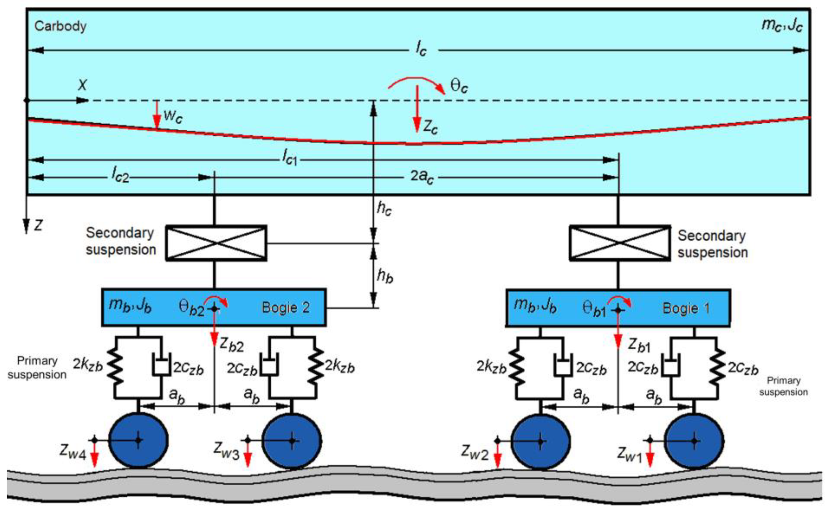
2. Railway Vehicle Model

2.1. Description of the Vehicle Model

Figure 1 shows the mechanical model for the study of vertical vibrations of a four-axle passenger railway vehicle with two suspension stages travelling at constant velocity on a track with vertical irregularities. The vehicle model is a rigid–flexible coupled type model. The vehicle car body is modeled by a free-free equivalent beam, with a constant section and uniformly distributed mass of Euler–Bernoulli type. The chassis of the two bogies and the four wheelsets are represented by rigid bodies.
The vertical vibration modes of the car body are bounce zc, pitch θc and the first vertical bending mode; and the vibration modes of the two bogies are bounce zb1,2 and pitch θb1,2. The car body has mass mc and inertia moment Jc. Each bogie has mass mb and inertia moment Jb.
The vertical irregularities of the track impose vertical displacements of the wheelsets, denoted by zw1...4. Since the eigenfrequencies of the considered vertical vehicle vibration modes are much lower than the frequencies of the wheelset–track system, the perfectly rigid track was considered.
The secondary suspension is represented by four different models: one reference model and three analysis models (Figure 2). The first model (model A) is a simple, reference model consisting of a Kelvin–Voigt system for translation in the vertical direction, with stiffness 2kzc and damping constant 2czc. The second model (model B) consists of model A and a Kelvin–Voigt system for rotation, with angular stiffness 2kθc and damping constant 2cθc, which takes the relative angular displacement between the car body and bogie. Model C results from the composition of model A with a Kelvin–Voigt system for longitudinal translation, which models the transmission system of the longitudinal forces between the bogie and the car body. This system is positioned at a distance hc from the medium fiber of the car body and at a distance hb from the center of gravity of the bogie and has the elastic constant 2kxc and the damping constant 2cxc. The fourth model (model D) is a complete model consisting of three Kelvin–Voigt systems for vertical translation, for rotation and for longitudinal translation.
The primary suspension corresponding to a wheelset is modeled by a Kelvin–Voigt system for vertical translation, with elastic constant 2kzb and damping constant 2czb.
The longitudinal base of the secondary suspension is 2ac, and the longitudinal base of the primary suspension is 2ab. Distances lc1,2 = lc/2 ± ac define the support points of the car body on the secondary suspension, where lc is the length of the car body.
The vertical displacement wc(x,t) of a section of the car body at a distance x from the origin of the reference system at time t is the result of the superposition of the three modes of vibration–bounce, pitch and the first vertical bending mode,
w c ( x , t ) = z c ( t ) + ( x l c 2 ) θ c ( t ) + X c ( x ) T c ( t )
where Tc(t) is the time coordinate and Xc(x) is its eigenfunction of the first vertical bending mode
X c ( x ) = sin β x + sinh β x sin β l c sinh β l c cos β l c cosh β l c ( cos β x + cosh β x )
with
β = ω c 2 ρ c / ( E c I c ) 4
which checks the characteristic equation,
cos β l c cosh β l c 1 = 0 ,
where: ωc is the natural angular frequency of the first vertical bending mode of the car body; ρ c = mc/lc represents the mass of the beam per unit length; EcIc is the bending stiffness, where Ec is the longitudinal modulus of elasticity, and Ic is the moment of inertia of the cross-section of the beam.

2.2. The Equations of Motion

The general form of the equation of motion of the car body is obtained using the Euler–Bernoulli beam theory, and the equations of motion for bounce, pitch and vertical bending are obtained by the method of modal analysis [48]. The bounce and pitch equations of the two bogies are deduced using the fundamental laws of mechanics.
Corresponding to each of the four models of the secondary suspension, a system of seven equations of motion of the vehicle results (see Appendix A, Appendix B, Appendix C and Appendix D), which can be written in the matrix of the form:
M q ¨ + C q ˙ + K q = P z ˙ ¨ w + R z ˙ w
where q represents the vector of displacement coordinates, zw is the vector of non-homogeneous terms. Matrices M, C and K are inertia, damping and stiffness matrices.
In the following subsections, the general forms of the equations of motion of the car body and bogies corresponding to each of the four models adopted for the secondary suspension are presented. It is specified that the form of the car body bounce and bogie bounce equations of motion (see Equations (8) and (12)) is not influenced by the secondary suspension model. To avoid a repetitive presentation, these equations are only presented in Section 2.2.1. Instead, the car body vertical bending equation and the pitch equations of the car body and bogies change depending on the secondary suspension model, as will be shown next.

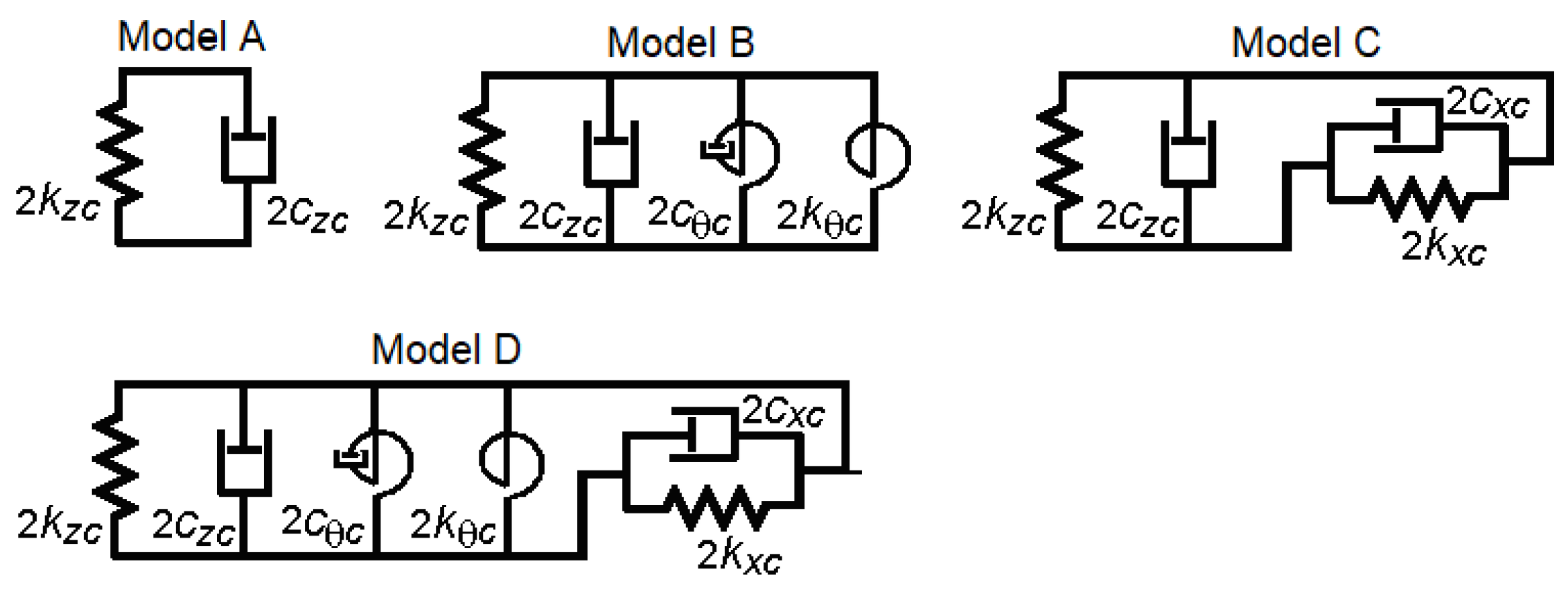
2.2.1. The Equations of Motion for Model A of the Secondary Suspension

The equation of motion of the car body has the general form
E I 4 w c ( x , t ) x 4 + μ I c 5 w c ( x , t ) x 4 t + ρ c 2 w c ( x , t ) t 2 = i = 1 2 F z c i δ ( x l c i )
where δ(.) is Dirac’s delta function, μ is the structural damping coefficient, and Fzc1,2 represents the vertical forces from the secondary suspension,
F z c 1 , 2 = 2 c z c [ w c ( l c 1 , 2 , t ) t z ˙ b 1 , 2 ] 2 k z c [ w c ( l c 1 , 2 , t ) z b 1 , 2 ]
Through the method of modal analysis, from Equation (6), the equations of motion of bounce, pitch and the vertical bending of the car body are obtained:
m c z ¨ c = i = 1 2 F z c i
J c θ ¨ c = i = 1 2 F z c i ( l c i l c 2 )
m m c T ¨ c + c m c T ˙ c + k m c T c = i = 1 2 F z c i X c ( l c i )
In Equation (10), mmc represents the modal mass of the car body, cmc is modal damping of the car body, and kmc is modal stiffness of the car body and is calculated with the relations:
m m c = ρ c 0 L X c 2 d x ,   c m c = μ I c 0 L ( d 2 X c d x 2 ) 2 d x , k m c = E c I c 0 L ( d 2 X c d x 2 ) 2 d x
The bounce and pitch equations of bogies are of the form:
m b z ¨ b 1 = j = 1 2 F z b j F z c 1 ,   m b z ¨ b 2 = j = 3 4 F z b j F z c 2
J b θ ¨ b 1 = a b j = 1 2 ( 1 ) j + 1 F z b j ,   J b θ ¨ b 2 = a b j = 3 4 ( 1 ) j + 1 F z b j
where Fzb1,2 and Fzb3,4 represent the forces from the primary suspension of the wheelsets 1 and 2, respectively wheelsets 3 and 4,
F z b 1 , 2 = 2 c z b ( z ˙ b 1 ± a b θ ˙ b 1 z ˙ w 1 , 2 ) 2 k z b ( z b 1 ± a b θ b 1 z w 1 , 2 )
F z b 3 , 4 = 2 c z b ( z ˙ b 2 ± a b θ ˙ b 2 z ˙ w 3 , 4 ) 2 k z b ( z b 2 ± a b θ b 2 z w 3 , 4 )
The final form of the equations of motion is shown in Appendix A. It is noted that, in the case of the secondary suspension model A, the pitch vibrations of the bogies are manifested as independent vibrations, and the bounce, pitch and vertical bending vibrations of the car body are coupled with the bounce vibrations of the bogies.

2.2.2. The Equations of Motion for Model B of the Secondary Suspension

The equation of motion of the car body has the general form:
E c I c 4 w c ( x , t ) x 4 + μ I c 5 w c ( x , t ) x 4 t + ρ c 2 w c ( x , t ) t 2 = i = 1 2 F z c i δ ( x l c i ) + i = 1 2 M c i d δ ( x l c i ) d x
where Mc1,2 represents the moments due to the secondary suspension,
M c 1 , 2 = 2 c θ c ( 2 w c ( l c i , t ) x t θ ˙ b 1 , 2 ) 2 k θ c [ w c ( l c i , t ) x θ b 1 , 2 ]
The equations of motion of the pitch and the vertical bending of the car body are
J c θ ¨ c = i = 1 2 F z c i ( l c i l c 2 ) i = 1 2 M c i
m m c T ¨ c + c m c T ˙ c + k m c T c = i = 1 2 F z c i X c ( l c i ) + i = 1 2 M c i d X c ( l c i ) d x
The equations of motion of the pitch of the bogies are
J b θ ¨ b 1 = a b j = 1 2 ( 1 ) j + 1 F z b j M c 1 ,   J b θ ¨ b 2 = a b j = 3 4 ( 1 ) j + 1 F z b j M c 2
The final form of the equations of motion is shown in Appendix B. By introducing the rotation system into the secondary suspension model, the pitch vibrations of the bogies are transmitted to the car body and coupled with the pitch and vertical bending vibrations of the car body. As the pitch and vertical bending vibrations of the car body are coupled to the bounce vibrations of the car body and bogies, a coupling also occurs between the pitch vibrations of the bogies and the bounce vibrations of the vehicle.

2.2.3. The Equations of Motion for Model C of the Secondary Suspension

The equation of motion of the car body has the general form:
E c I c 4 w c ( x , t ) x 4 + μ I c 5 w c ( x , t ) x 4 t + ρ c 2 w c ( x , t ) t 2 = i = 1 2 F z c i δ ( x l c i ) h c i = 1 2 F x c i d δ ( x l c i ) d x
where Fxc1,2 represents the longitudinal forces from the secondary suspension,
F x c 1 , 2 = 2 c x c ( h c 2 w c ( l c 1 , 2 , t ) x t + h b θ ˙ b 1 , 2 ) + 2 k x c ( h c w c ( l c 1 , 2 , t ) x + h b θ b 1 , 2 )
The pitch and vertical bending equations of the car body take the form:
J c θ ¨ c = i = 1 2 F z c i ( l c i l c 2 ) + h c i = 1 2 F x c i
m m c T ¨ c + c m c T ˙ c + k m c T c = i = 1 2 F z c i X c ( l c i ) h c i = 1 2 F x c i d X c ( l c i ) d x
The pitch equations of the bogies take the form:
J b θ ¨ b 1 = a b j = 1 2 ( 1 ) j + 1 F z b j h b F c x 1 ,   J b θ ¨ b 2 = a b j = 3 4 ( 1 ) j + 1 F z b j h b F c x 1
The final form of the equations of motion is shown in Appendix C. Through the longitudinal system contained in the C model of the secondary suspension, the pitch vibrations of the bogies are transmitted to the car body, resulting in the coupling of this vibration mode with the other vibration modes of the vehicle, as described in the previous section.

2.2.4. The Equations of Motion for Model D of the Secondary Suspension

The equation of motion of the car body corresponding to model D of the suspension has the general form:
E c I c 4 w c ( x , t ) x 4 + μ I c 5 w c ( x , t ) x 4 t + ρ c 2 w c ( x , t ) t 2 = i = 1 2 F z c i δ ( x l c i ) + i = 1 2 ( M c i h c F x c i ) d δ ( x l c i ) d x   ,
The pitch and vertical bending equations of the car body are the form:
J c θ ¨ c = i = 1 2 F z c i ( l c i l c 2 ) i = 1 2 ( M c i h c F x c i )
m m c T ¨ c + c m c T ˙ c + k m c T c = i = 1 2 F z c i X c ( l c i ) + i = 1 2 ( M c i h c F x c i ) d X c ( l c i ) d x
The pitch equations of the bogies are
J b θ ¨ b 1 = a b j = 1 2 ( 1 ) j + 1 F z b j M c 1 h b F c x 1 ,   J b θ ¨ b 2 = a b j = 3 4 ( 1 ) j + 1 F z b j M c 2 h b F c x 1
The final form of the equations of motion is shown in Appendix D. In these cases, the pitch vibrations of the bogies are transmitted to the car body through both systems included in the secondary suspension model—the rotation system and the longitudinal system.

3. Calculation of Frequency Response Functions of the Car Body

For the calculation of the frequency response functions of the car body, it is considered that the vertical irregularities of the track are of harmonic form with wavelength Λ and amplitude zw0. Next to each wheelset, the vertical irregularities of the track are described by the functions:
z w 1 , 2 ( x ) = z w 0 cos 2 π Λ ( x + a c ± a b ) ;   z w 3 , 4 ( x ) = z w 0 cos 2 π Λ ( x a c ± a b )
where x = V t is the coordinate of the center of the car body.
The functions zw1...4 is written as harmonic time functions of the form:
z w 1 , 2 ( t ) = z w 0 cos ω ( t + a c ± a b V ) ;   z w 3 , 4 ( t ) = z w 0 cos ω ( t a c a b   V )
where ω = 2πV/Λ represents the angular frequency induced by the vertical irregularities of the track.
It is assumed that the response of the vehicle is also harmonic with the same angular frequency as the frequency as that induced by the excitation by the vertical irregularities of the track. In this hypothesis, the coordinates describing the movements of the vehicle can be written in the general form:
q k ( t ) = Q k cos ( ω t + α k ) ,   cu k = 1 ÷ 7
where Qk is the displacement amplitude, and αk is the phase of the coordinate k compared to the vertical irregularities of the track respect to the vehicle center.
In the system of Equation (5), the complex value associated with the real ones are introduced (for i2 = −1):
z ¯ w 1...4 ( t ) = Z ¯ w 01 w 04 e i ω t
q ¯ k ( t ) = Q ¯ k e i ω t ,   for k = 1 ÷ 7
with
q ¯ 1 ( t ) = z ¯ c ( t ) = Z ¯ c 0 e i ω t ,   q ¯ 2 ( t ) = θ ¯ c ( t ) = Θ ¯ c 0 e i ω t ,   q ¯ 3 ( t ) = T ¯ c ( t ) = T ¯ c 0 e i ω t ,
q ¯ 4 ( t ) = z ¯ b 1 ( t ) = Z ¯ b 01 e i ω t ,   q ¯ 5 ( t ) = z ¯ b 2 ( t ) = Z ¯ b 02 e i ω t ,
q ¯ 6 ( t ) = θ ¯ b 1 ( t ) = Θ ¯ b 01 e i ω t ,   q ¯ 7 ( t ) = θ ¯ b 2 ( t ) = Θ ¯ b 02 e i ω t ,
where Z ¯ w 01 w 04 , Z ¯ c 0 , Θ ¯ c 0 , T ¯ c 0 , Z ¯ b 01 , b 02 , Θ ¯ b 01 , 02 are the complex amplitudes:
Z ¯ w 01 = Z w 0 e i ( 2 π / V ) ( a c + a b ) ,   Z ¯ w 02 = Z w 0 e i ( 2 π / V ) ( a c a b ) ,   Z ¯ w 03 = Z w 0 e i ( 2 π / V ) ( - a c + a b ) ,   Z ¯ w 04 = Z w 0 e i ( 2 π / V ) ( - a c a b )
Z ¯ c 0 = Z c e i α z c ,   Θ ¯ c 0 = Θ c 0 e i α θ c ,   T ¯ c 0 = T c e i α T c ,   Z ¯ b 01 , b 02 = Z b 01 , b 02 e i α z b 1 , z b 2 ,   Θ ¯ b 01 , b 02 = Θ b 01 , b 02 e i α θ 1 , θ 2 .
A linear system of non-homogeneous algebraic equations is thus obtained:
( ω 2 M + A ) Q ¯ = B
The following notations are introduced:
α z c = 2 ( i ω c z c + k z c ) ,   α x c = 2 ( i ω c x c + k x c ) ,   α θ c = 2 ( i ω c θ c + k θ c )
α m 2 = i ω c m 2 + k m 2 ,   α z b = 2 ( i ω c z b + k z b ) .
The vectors Q and B are of the form:
Q ¯ = [ Q ¯ 1 Q ¯ 2 .... Q ¯ 7 ] T
B = α z b [ 0 0 0 exp [ i ω ( a c + a b ) / V ] + exp [ i ω ( a c a b ) / V ] exp [ i ω ( a c + a b ) / V ] exp [ i ω ( a c a b ) / V ] exp [ i ω ( a c + a b ) / V ] + exp [ i ω ( a c a b ) / V ] exp [ i ω ( a c + a b ) / V ] exp [ i ω ( a c a b ) / V ] ]
The matrices M and A are of the form:
M = diag ( m c J c m m 2 m b m b J b J b )
A = [ 2 α z c 0 2 ε α z c α z c 0 α z c 0 0 A 1 0 a c α z c A 3 a c α z c A 3 2 ε α z c 0 A 2 ε α z c λ A 3 ε α z c λ A 3 α z c a c α z c ε α z c 2 α z b + α z c 0 0 0 α z c a c α z c ε α z c 0 2 α z b + α z c 0 0 0 A 3 λ A 3 0 0 A 4 0 0 A 3 λ A 3 0 0 0 A 4 ]
in which the terms A1…4 change depending on the model of the secondary suspension as follows:
-
for model A,
A 1 = 2 a c 2 α z c ,   A 2 = α m 2 + 2 ε 2 α z c ,   A 3 = 0 ,   A 4 = 2 a b 2 α z b .
-
for model B,
A 1 = 2 a c 2 α z c + 2 α θ c ,   A 2 = α m 2 + 2 ε 2 α z c + 2 λ 2 α θ c ,   A 3 = α θ c ,   A 4 = 2 a b 2 α z b + α θ c .
-
for model C,
A 1 = 2 a c 2 α z c + 2 h c 2 α x c , A 2 = α m 2 + 2 ε 2 α z c + 2 h c 2 λ 2 α x c ,   A 3 = h c h b α x c ,   A 4 = 2 a b 2 α z b + h b 2 α x c .
-
for model D,
A 1 = 2 a c 2 α z c + 2 h c 2 α x c + 2 α θ c ,   A 2 = α m 2 + 2 ε 2 α z c + 2 h c 2 λ 2 α x c + 2 λ 2 α θ c ,
A 3 = h c h b α x c α θ c ,   A 4 = 2 a b 2 α z b + h b 2 α x c + α θ c .
From the system of Equation (34), the frequency response functions of the acceleration of the vehicle car body corresponding to the three modes of vibration, bounce, pitch, and vertical bending are obtained:
H ¯ z c ( ω ) = ω 2 Z ¯ c o ( ω ) Z ¯ w o ,   H ¯ θ c ( ω ) = ω 2 Θ ¯ c 0 ( ω ) Z ¯ w o ,   H ¯ T c ( ω ) = ω 2 T ¯ c 0 ( ω ) Z ¯ w o
The response function of the acceleration of the car body at some point x located on the longitudinal axis of the car body that passes through its center of mass is calculated with the relation:
H ¯ c ( x , ω ) = H ¯ z c ( ω ) + ( l c 2 x ) H ¯ θ c ( ω ) + X c ( x ) H ¯ T c ( ω )
Relation (36) can be customized to calculate the acceleration response function at the middle of the car body (for x = lc/2) or above the supporting points of the car body on the secondary suspension corresponding to one of the two bogies (for x = lc1,2):
H ¯ c m ( ω ) = H ¯ c ( l c 2 , ω ) = H ¯ z c ( ω ) + X c ( l c 2 ) H ¯ T c ( ω )
H ¯ c b 1 , c b 2 ( ω ) = H ¯ c ( l c 1 , 2 , ω ) = H ¯ z c ( ω ) ± a c H ¯ θ c ( ω ) + X c ( l c 1 , 2 ) H ¯ T c ( ω )

4. Calculation of the Power Spectral Density of the Acceleration of the Car Body

The general calculation relation of the power spectral density of the acceleration of the car body is
G c ( x , ω ) = G ( ω ) | H ¯ c ( x , ω ) | 2
where the frequency response function of the acceleration of the car body H ¯ c ( x , ω ) was previously defined (see Equation (36)), and G(ω) is the power spectral density of the vertical track irregularities. For the average statistical properties of European railways, the power spectral density described by the relation [49]
G ( ω ) = A Ω c 2 V 3 [ ω 2 + ( V Ω c ) 2 ] [ ω 2 + ( V Ω r ) 2 ]
is considered representative. The notations in relation (36) have the following significance: Ω is the wavenumber, Ωc= 0.8246 rad/m, Ωr= 0.0206 rad/m; A is a constant that depends on the quality of the track (for a good-quality track A = 2119·10−7 radm and for a low-quality track A = 6124·10−7 radm).
Relation (39) can be adapted to calculate the power spectral density of the acceleration at the middle of the car body or above the support points of the car body on the secondary suspension corresponding to one of the two bogies, as follows:
G c m ( ω ) = G ( ω ) | H ¯ c m ( ω ) | 2
G c b 1 , 2 ( ω ) = G ( ω ) | H ¯ c b 1 , 2 ( ω ) | 2
Based on the dynamic response expressed in the form of the power spectral density of the car body acceleration, the root mean square of the acceleration can be calculated with the general relation
a c ( x ) = 1 π G c ( x , ω ) d ω
which can be customized to calculate the root mean square of the acceleration at the middle of the car body or above the support points of the car body on the secondary suspension,
a c m = 1 π G c m ( ω ) d ω
a c b 1 , 2 = 1 π G c b 1 , 2 ( ω ) d ω

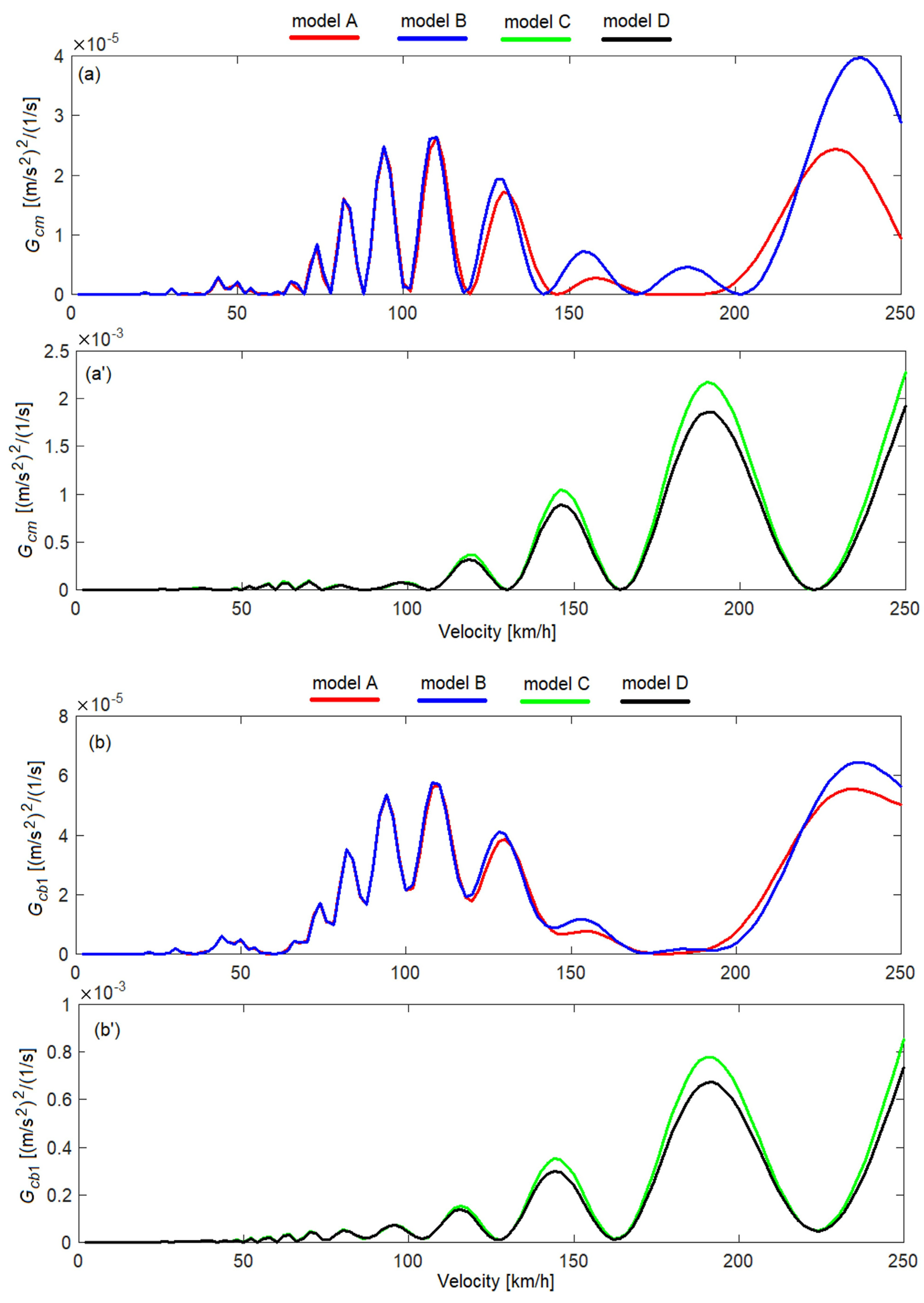
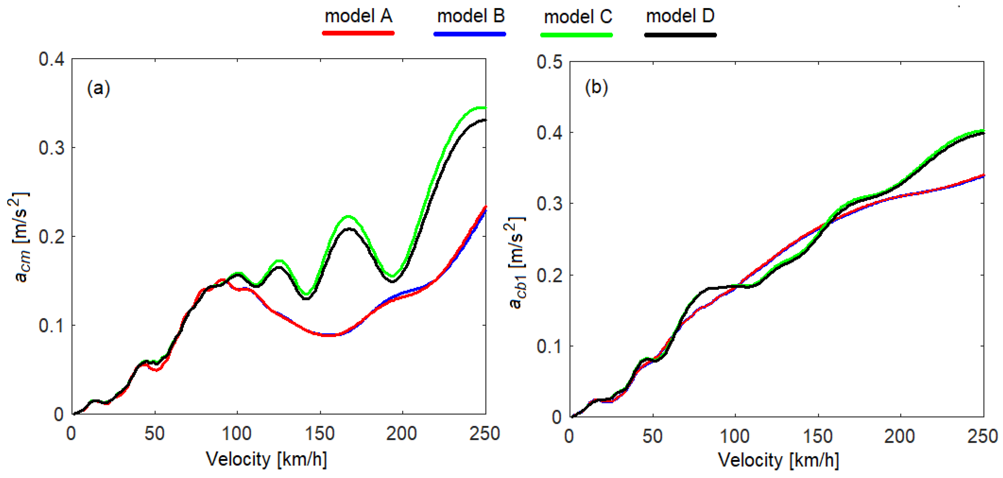
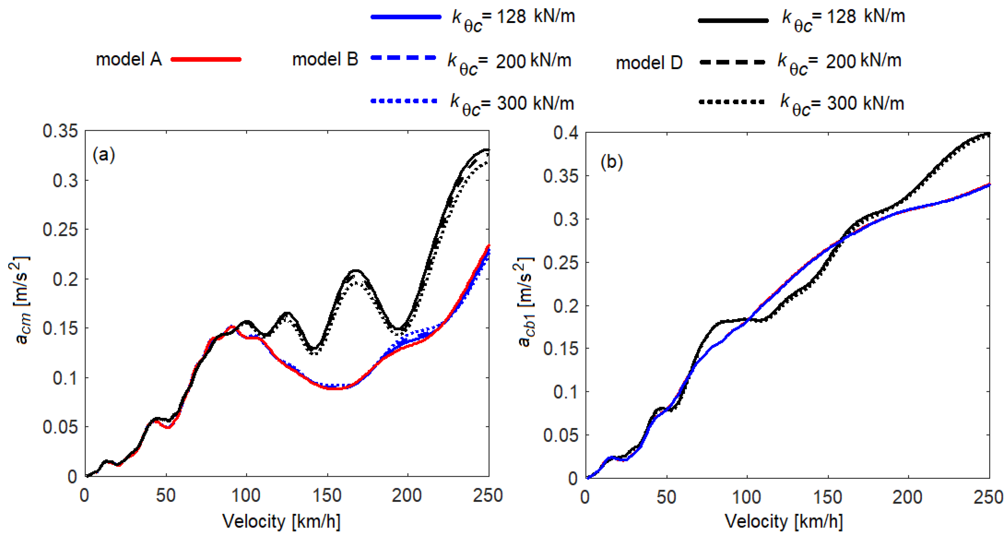
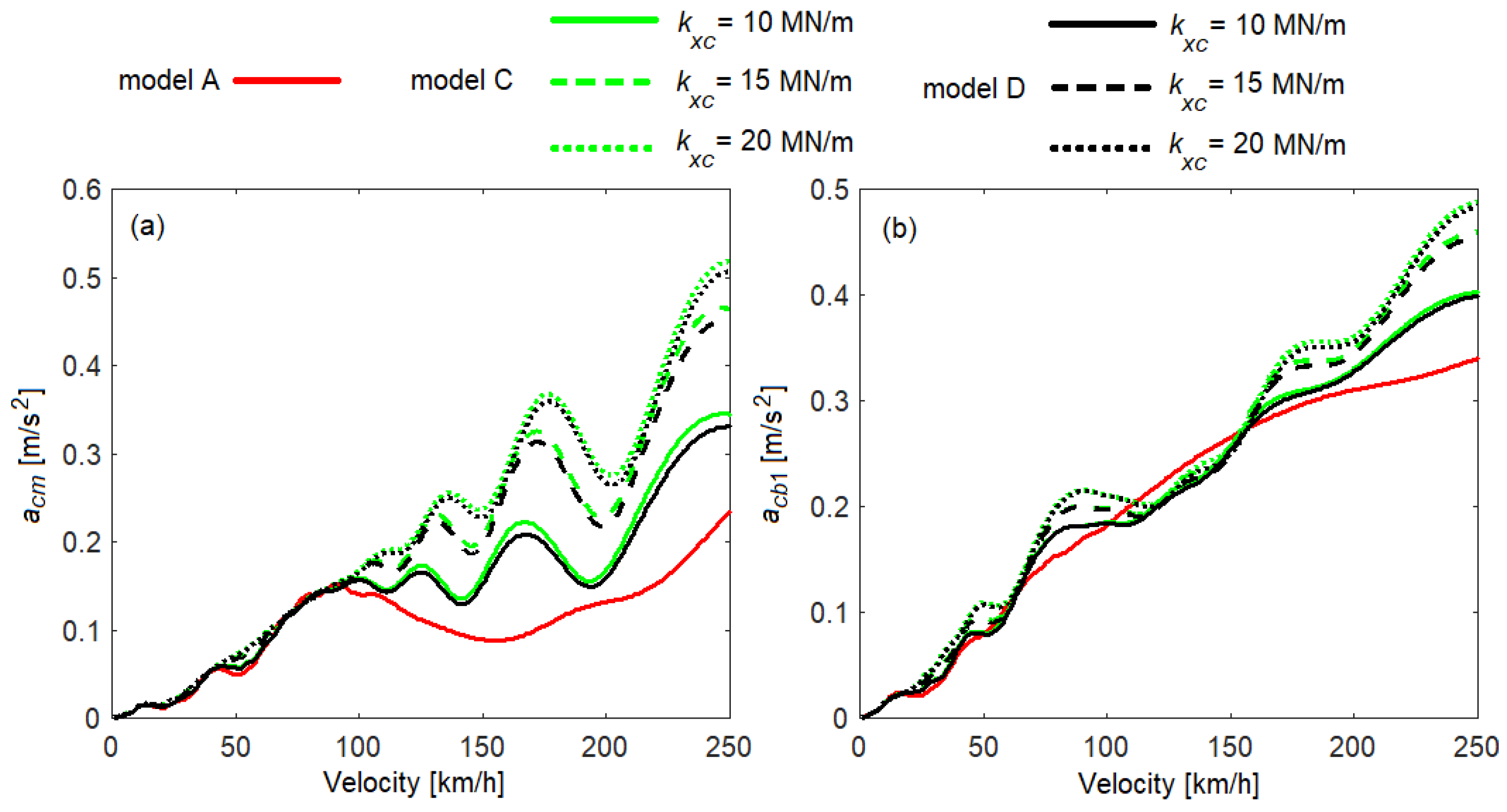
5. Evaluation of the Vertical Vibration Behavior of the Railway Vehicle Car Body Based on Numerical Simulations

5.1. Parameters of the Numerical Model of the Railway Vehicle

The reference parameters of the railway vehicle used in the numerical simulations are presented in Table 1.

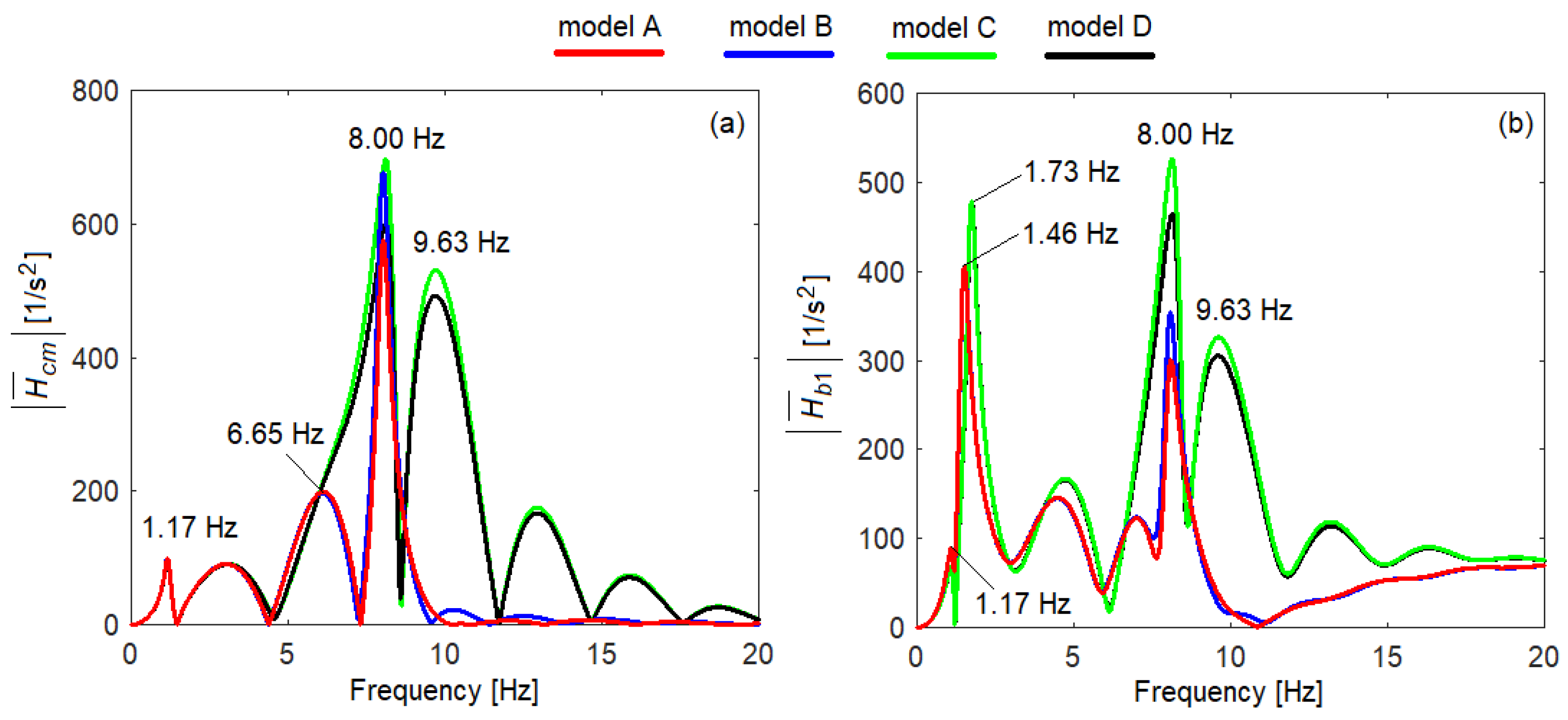
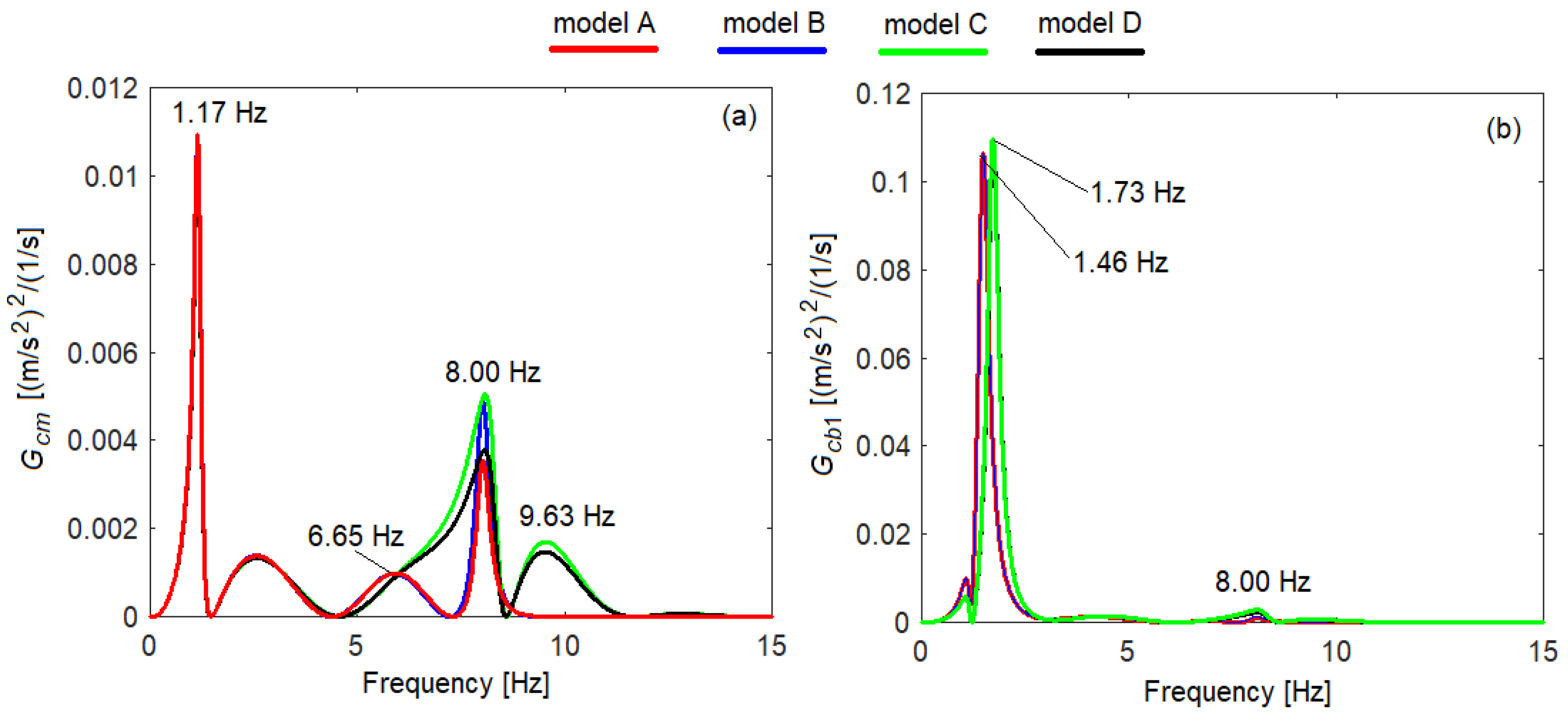
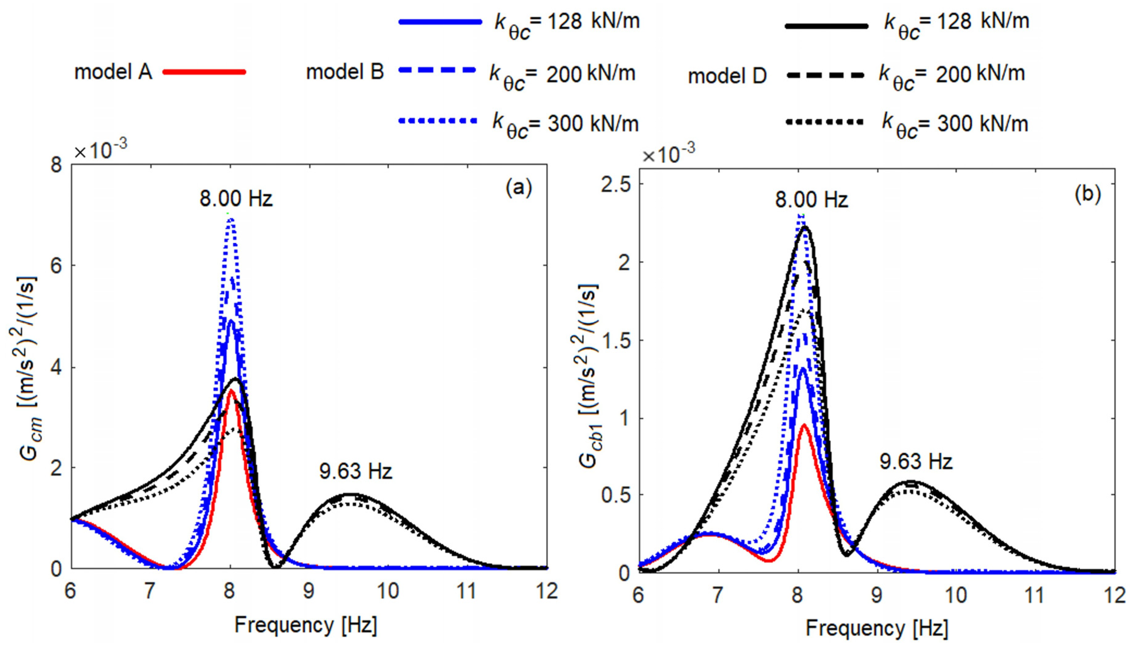
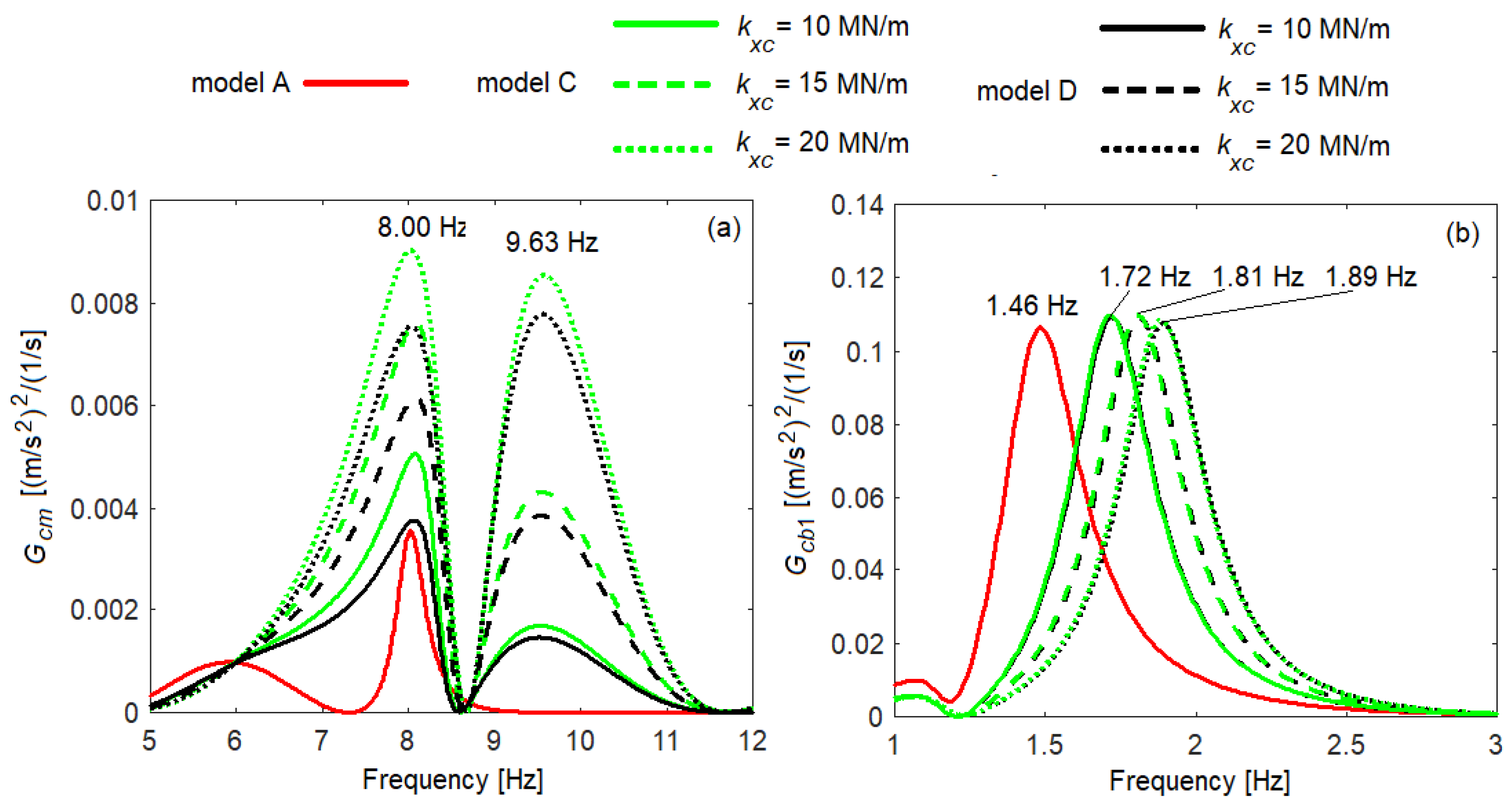
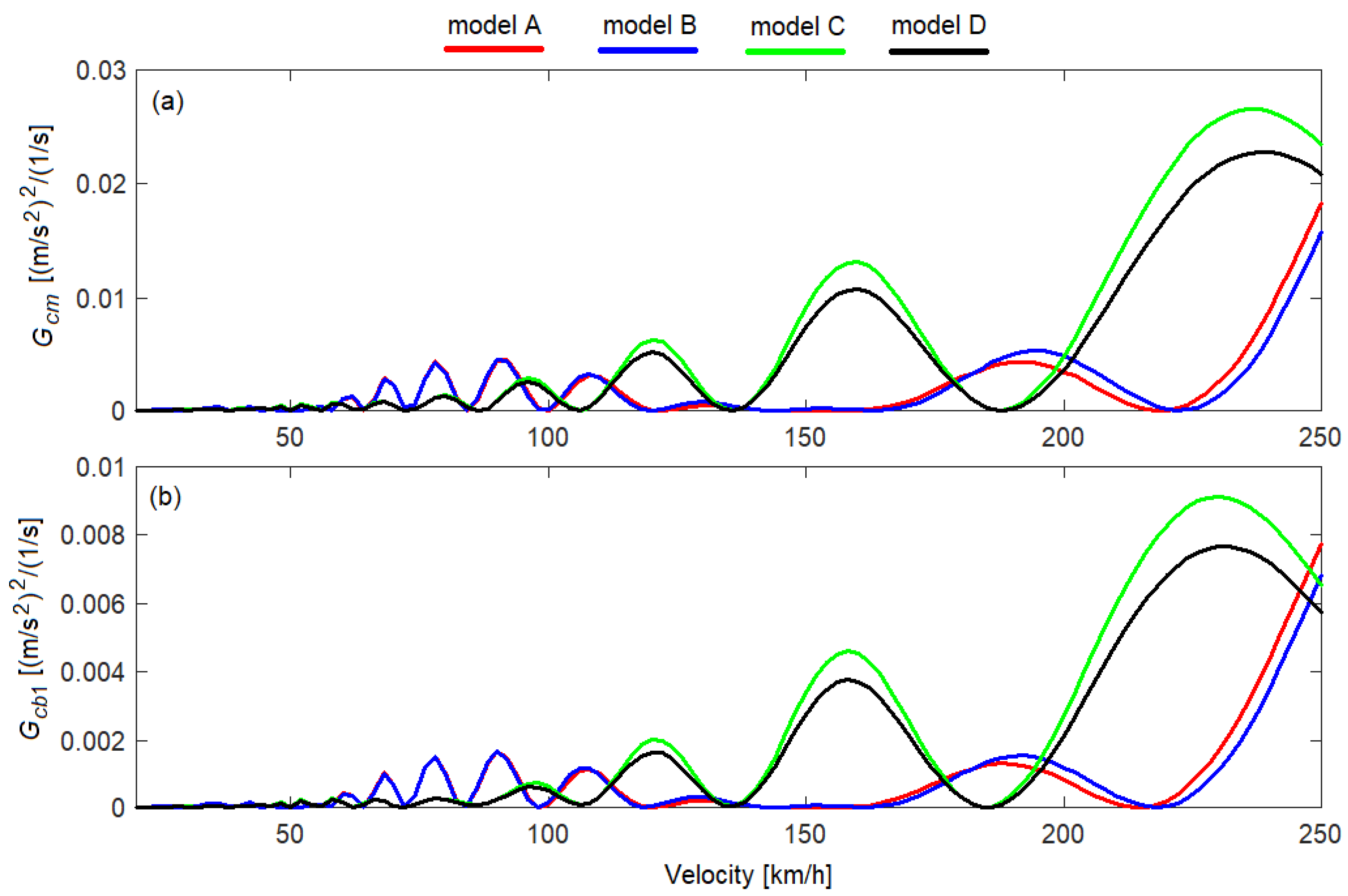
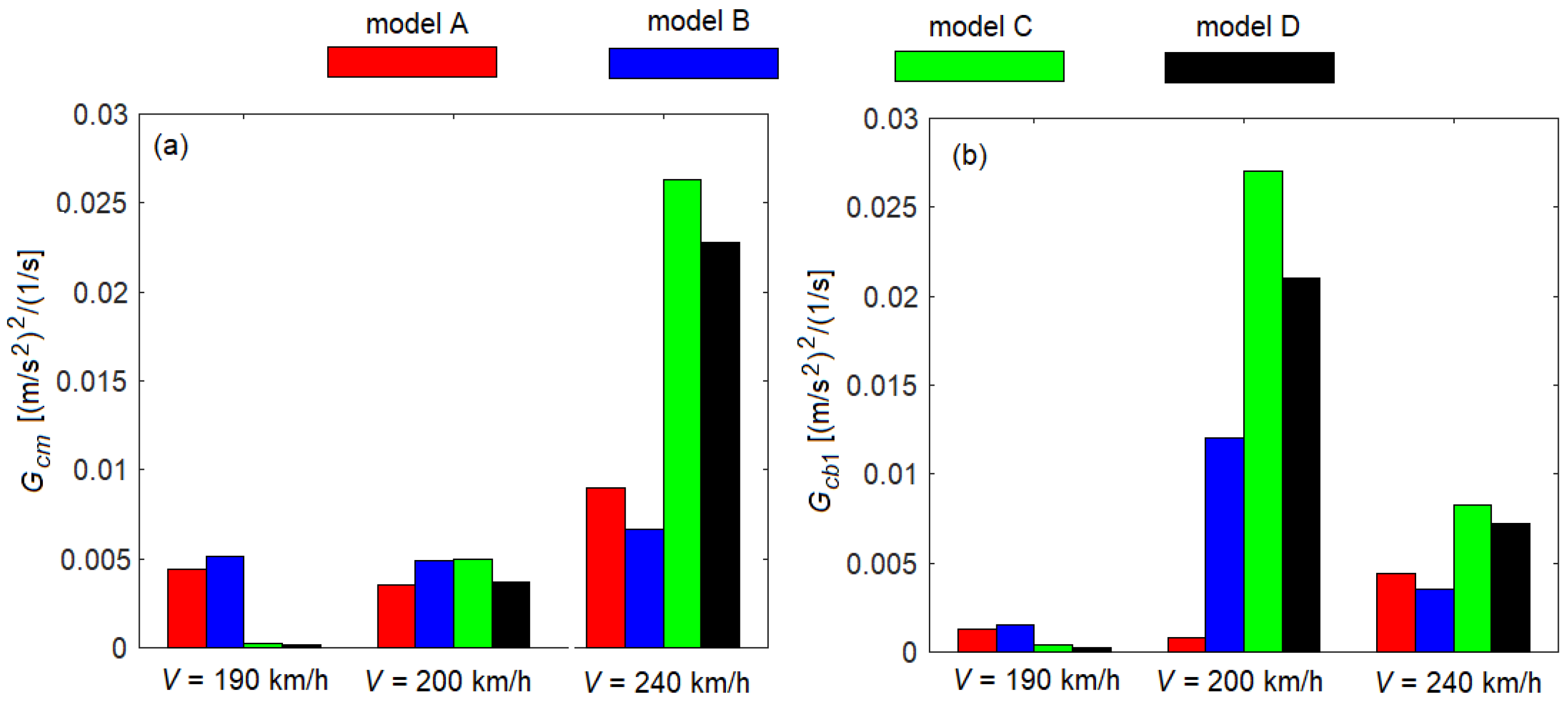
5.2. Numerical Simulation Results and Discussion

In this section, the results of the numerical simulations regarding the influence of the secondary suspension model on the vertical vibration behavior of the railway vehicle car body are presented. The numerical simulation applications were developed in the MATLAB software environment. The vibration behavior of the car body is evaluated based on the acceleration frequency response functions, the acceleration power spectral density and the root mean square acceleration of the car body, for the four models of the secondary suspension—model A, model B, model C and model D.
Figure 3 shows the frequency response functions of the acceleration of the car body at its middle (diagram a) and above the support point on the secondary suspension corresponding to bogie 1 (diagram b), at a velocity of 200 km/h, for the four secondary suspension models. The peaks corresponding to the eigenfrequencies of the vehicle’s vibration modes are highlighted on both diagrams. The values of the eigenfrequencies of the vibration modes of the car body and bogies are centralized in Table 2. It is observed that the eigenfrequencies of the bounce and vertical bending of the car body and the eigenfrequencies of the bounce and pitch of the bogie do not change for any of the three analysis models relative to the reference model A. The eigenfrequency of the pitch vibration of the car body is maintained at 1.46 Hz in the case of the B model. By introducing into the model of the secondary suspension of the longitudinal system in models C and D, the eigenfrequency of the car body pitch increases to 1.72 Hz.
In addition to the peaks corresponding to the eigenfrequencies of the vehicle’s vibration modes, a series of minima of the response functions corresponding to the geometric filtering effect are highlighted. The geometric filtering effect is an important characteristic of the vertical vibrations of railway vehicles, analyzed in several papers [7,39,50,51,52]. In short, the geometric filtering effect is the result of the phase shifts between the vertical movements of the wheelsets generated by track irregularities; these phase shifts are due to the distance between the wheelsets and the velocity of the vehicle. Geometric filtering has a selective character, depending on the velocity, and has a differentiated efficiency along the vehicle car body. Due to the geometric filtering effect, a sequence of maxima and minima appear in the response of the vehicle car body, depending on the distance between the wheelsets (the wheelbase of the car body and the wheelbase of the bogie) and the velocity. The maxima correspond to the situation in which geometric filtering does not work, and the minima appear in the form of anti-resonance frequencies corresponding to the geometric filtering frequencies. If the anti-resonance frequencies coincide with the eigenfrequencies of one of the vehicle’s vibration modes, its influence is greatly reduced. Thus, the change in the weights of the vehicle’s vibration modes depending on the velocity is explained. By this, the fact that the vibration regime does not intensify continuously with the increase of the velocity is also understood, as will be shown later (see Figures 7 and 8).
From the point of view of the vibration level of the car body, the influence of the suspension model is manifested, for all three analysis models, at the frequency of 8 Hz—the eigenfrequency of the vertical bending vibrations of the car body. The pitch vibration of the car body is, however, only influenced in the case of the C and D models of the secondary suspension. This can be explained by a weak coupling between the pitch vibration of the bogies and the pitch vibration of the car body in the case of the B model of the secondary suspension. It is also noted that the vibration level of the car body increases significantly at the frequency of 9.63 Hz—the eigenfrequency of the pitch vibration of the bogie, only in the case of the C and D models of the suspension. The conclusion is that the longitudinal system in the secondary suspension is the one that has an important contribution in transmitting the pitch vibrations of the bogies to the car body, while the rotation system contributes less. In model D, the contribution of the two systems does not add up, since the two systems work in antiphase. All these observations are also highlighted in the case of the acceleration power spectral density, presented in the diagrams in Figure 4.
According to diagram (a) of Figure 4, at the middle of the car body, the secondary suspension model influences the vibration level at the eigenfrequencies of the vertical bending of the car body and the bogie pitch. For the velocity of 200 km/h, at the frequency of vertical bending, at 8 Hz, all three analysis models—model B, model C and model D, lead to an increase in the vibration level of the car body compared to the reference model A. At the bogie pitch frequency of 9.63 Hz, only analysis models C and D significantly influence the vibration level of the car body, which increases compared to the vibration level corresponding to the reference model A. As shown, above the support point of the car body on the secondary suspension (diagram b), the C and D models of the secondary suspension influence the eigenfrequency of the car body pitch, which increases from 1.46 Hz to 1.73 Hz due to the longitudinal system.
Based on these last observations, it is interesting to analyze how the stiffness of the system for rotation and, respectively, the stiffness of the longitudinal system, influence the vibration regime of the car body at the eigenfrequencies of vertical bending of the car body, bogie pitch and car body pitch.
The diagrams in Figure 5 show the influence of the stiffness of the system for rotation contained in model B of the secondary suspension and on the vibration level of the car body in model D at the eigenfrequency of the vertical bending (8 Hz) and at the eigenfrequency of the bogie pitch (9.63 Hz) at a velocity of 200 km/h. The increased stiffness of the rotation system in model B leads to an increase in the vibration level of the car body at the frequency of 8 Hz. In model D, which also includes the longitudinal system (kxc = 10 MN/m), increasing the rotational stiffness of the system results in a reduction in the vibration level of the car body at both 8 Hz and 9.63 Hz, due to compensation effect as a result of the opposite action of the two systems working in antiphase.
Based on the diagram (a) in Figure 6, the influence of the stiffness of the longitudinal system, included in the C model of the secondary suspension, on the vibration level of the car body at the eigenfrequency of the vertical bending of the car body and at the eigenfrequency of the pitch vibration of the bogie is analyzed. When increasing the stiffness of the longitudinal system, important increases in the vibration level are obtained at both eigenfrequencies. For example, at the frequency of 8 Hz, compared to reference model A, the increase of the acceleration power spectral density is 43.34% for kxc = 10 MN/m, 115.29% for kxc = 15 MN/m and 154.95% for kxc = 15 MN/m. In the case of model D, for kθc = 128 kN/m, the increase of the vibration level is lower: 5.71% for kxc = 10 MN/m, 74.28% for kxc = 15 MN/m and 114.28% for kxc = 20 MN/m. Diagram (b) of Figure 6 highlights the increase of the eigenfrequency of the car body pitch when the stiffness of the longitudinal system in the C model of the secondary suspension increases from 1.72 Hz (for kxc = 10 MN/m) to 1.81 Hz (for kxc = 15 MN/m) and at 1.89 Hz (for kxc = 20 MN/m) without significant changes in the vibration level.
The results presented in Figure 4, Figure 5 and Figure 6 regarding the increase the vertical bending vibration level of the car body at 200 km/h for suspension analysis models B, C and D relative to reference model A are not generally valid for any velocity due to geometric filtering effect, and this is highlighted in Figure 7.
In Figure 7, the power spectral density of the acceleration for the four models is represented over a speed range between 10 km/h and 250 km/h, at the eigenfrequency of the vertical bending of the car body. As previously mentioned, it is also observed here that the vibration level of the car body does not increase continuously with velocity. Over the entire speed range, the power spectral density alternately has maxima and minima corresponding to the geometric filtering velocities. It is interesting to note that the geometric filtering velocities change depending on the suspension model. Compared to the suspension reference model A, model B does not introduce significant changes of the geometric filtering velocities. In contrast, in the case of model C, the geometric filtering velocities change significantly, and this trend is also preserved in the case of model D. Under these conditions, since the vibration level of the car body changes according to the geometric filtering velocities, and they change according to the secondary suspension model, it is difficult to establish a clear trend regarding the influence of the suspension model on the vertical bending vibration level of the vehicle car body. The general trend is that the level of vertical bending vibration of the car body increases for models B, C and D of the secondary suspension compared to model A, as at the velocity of 200 km/h (see Figure 8). However, at some velocities, the vibration level of the car body is higher in the A model than in the other three models. For example, according to Figure 8 in which the power spectral density of the car body at the frequency of 8 Hz is represented, at the velocity of 190 km/h, the vibration level of the car body is higher for model A than for models C and D; at 240 km/h, it is higher than for the B model.
Figure 9 shows the power spectral density of the acceleration for the four models at the bogie pitch frequency. It is also noted here that for models C and D, the geometric filtering velocities change significantly compared to the reference model A. As previously shown, the vibration level of the car body at the eigenfrequency of the bogie pitch vibration increases significantly for C and D suspension models.
The root mean square of acceleration is an important quantity from the point of view of evaluating the vibration behavior of the railway vehicle. Based on the root mean square of acceleration, the dynamic performance of the railway vehicle can be evaluated in terms of ride quality and ride comfort.
Figure 10 shows the root mean square of the acceleration of the car body for the velocity range of 10 to 250 km/h for the reference numerical parameters of the railway vehicle model. The effects of geometric filtering on the root mean square of the car body acceleration, which does not increase continuously with velocity, can also be observed here. The geometric filtering effect is more pronounced in the middle of the car body, where the geometric filtering effect due to the bogie wheelbase and the geometric filtering effect produced by the car body wheelbase are combined. Above the secondary suspension, the geometric filtering effect is less effective because it is exclusively due to the geometric filtering effect given by the bogie wheelbase.
Regarding the influence of the secondary suspension model on the vibration behavior of the car body, it is highlighted that the rotation system included in the B suspension model does not significantly affect the vertical vibration level of the car body. The influence of the longitudinal system included in the C model of the suspension on the vibration level of the car body is more pronounced in the middle of the car body at velocities above 100 km/h. Above the secondary suspension, the influence of the C model of the suspension on the vibration level is noticeable at velocities above 200 km/h. For example, at the middle of the car body (diagram a), at a velocity of 165 km/h, the acceleration for model C is 139.98% higher than the acceleration obtained for the reference model A; At a velocity of 250 km/h, it is 47.22% greater. Above the supporting point of the car body on the secondary suspension (diagram b), at a velocity of 165 km/h, the root mean square of acceleration for model C is 4.87% higher than for model A, and at a velocity of 250 km/h by 18.46%. The values of the root mean square of the acceleration for the model D are not significantly different from those corresponding to model C.
As can be seen in Figure 11, increasing the stiffness of the rotating system does not significantly affect the root mean square of acceleration values of model B; for model D, the reduction in vibration level is modest. For example, in the middle of the car body, when increasing the stiffness kθc from 128 kN/m to 300 kN/m, the root mean square of the acceleration for model D decreases from 0.20 m/s2 to 0.19 m/s2 at a velocity of 165 km/h, and from 0.33 m/s2 to 0.32 m/s2 for a velocity of 250 km/h.
The influence of the stiffness of the longitudinal system, included in models C and D of the secondary suspension, on the root mean square of acceleration is highlighted in Figure 12. As previously shown, the influence of the longitudinal system on the vibration level of the car body is manifested especially at high speeds, and the increase in the stiffness of this system increases this effect even more. In the middle of the car body, when the stiffness kxc increases from 10 MN/m to 20 MN/m at a velocity of 165 km/h, the acceleration increases from 0.22 m/s2 to 0.32 m/s2; at 250 km/h, the acceleration increases from 0.34 m/s2 to 0.52 m/s2. Above the secondary suspension, at a velocity of 165 km/h, the acceleration of the car body increases from 0.29 m/s2 to 0.32 m/s2, and at 250 km/h, it increases from 0.40 m/s2 to 0.79 m/s2.
Finally, it should be mentioned that the theoretical results obtained with the D model of the secondary suspension were previously validated experimentally [53,54].

6. Conclusions

In the paper, the influence of the secondary suspension model in the evaluation of the vertical vibration behavior of the railway vehicle car body was analyzed based on numerical simulations. For this, a rigid–flexible coupled vehicle model was used, in which four different models of secondary suspension were integrated–a reference model (model A) and three analysis models (model B, model C and model D). The three analysis models include systems through which the pitch vibrations of the bogies are transmitted to the car body; a system that takes the relative angular displacement between the car body and the bogie and a system that models the transmission system of the longitudinal forces between the bogie and the car body were also studied. Under these conditions, the pitch vibrations of the bogies couple to the pitch and vertical bending vibrations of the car body and through them with the bounce vibrations of the car body and bogies. The effects of these two systems on the vibration behavior of the railway vehicle car body were analyzed both for each system separately, for model B and model C, and studied together with model D.
Based on the results of the numerical simulations regarding the frequency response functions of the acceleration and the power spectral density of the acceleration, the following relevant conclusions can be synthesized:
1.
The influence of the model of the secondary suspension is especially manifested on the vertical bending vibrations of the car body. For all three suspension analysis models, there is a general tendency to increase the level of vertical bending vibration compared to the reference suspension model. This trend may be affected by the geometric filtering effect and by the geometric filtering velocities that change according to the suspension model.
2.
The pitch vibrations of the car body are influenced only by the transmission system of the longitudinal forces between the bogie and the car body and are included in models C and D of the secondary suspension. It manifests itself by increasing the eigenfrequency of the pitch vibration without important changes in vibration level.
3.
The vibration level of the car body increases significantly at the eigenfrequency of the pitch vibrations of the bogie for models C and D of the suspension. Under these conditions, it can be concluded that the longitudinal system in the secondary suspension has an important contribution in transmitting the pitch vibrations of the bogies to the car body, while the rotation system contributes less.
From the point of view of the influence of the model of the secondary suspension on the vibration behavior of the car body, evaluated based on the root mean square of the car body acceleration, it is noted that the longitudinal system, introduced in the model C and model D of the secondary suspension, significantly changes the vertical vibration level of the car body, especially in the middle of it. At high speeds, there are significant increases of the car body acceleration, which can reach up to about 140% and can increase more depending on the stiffness of the longitudinal system.
These conclusions are useful in future research in which problems of evaluating the dynamic performance of the railway vehicle are addressed in terms of ride quality and ride comfort.

Author Contributions

Conceptualization, M.D.; methodology, M.D.; software, M.D. and I.I.A.; validation, M.D., I.I.A. and D.I.S.; formal analysis, M.D., I.I.A. and D.I.S.; investigation, M.D. and I.I.A.; resources, M.D., I.I.A. and D.I.S.; writing—original draft preparation, M.D.; writing—review and editing, M.D., I.I.A. and D.I.S.; supervision, M.D.; project administration, M.D. All authors have read and agreed to the published version of the manuscript.

Funding

Contribution of the authors Mădălina Dumitriu and Ioana Izabela Apostol to this work was supported by a grant of the Ministry of Research, Innovation and Digitization, CCCDI–UEFISCDI, project number PN-III-P2-2.1-PED-2021-0319, within PNCDI III. Contribution of the author Dragoș Ionuț Stănică to this work has been funded by the European Social Fund from the Sectorial Operational Programme Human Capital 2014–2020, through the Financial Agreement with title ‘‘Training of PhD students and postdoctoral researchers in order to acquire applied research skills–SMART’’, Contract no. 13530/2022, SMIS Code 153734.

Data Availability Statement

Not applicable.

Conflicts of Interest

The authors declare no conflict of interest.

Appendix A

Final form of the equations of motion for model A of the secondary suspension:
-
the equations of motion of the car body,
m c z ¨ c + 2 c z c [ 2 z ˙ c + 2 ε T ˙ c ( z ˙ b 1 + z ˙ b 2 ) ] + 2 k z c [ 2 z c + 2 ε T c ( z b 1 + z b 2 ) ] = 0
J c θ ¨ c + 2 c z c a c [ 2 a c θ ˙ c ( z ˙ b 1 z ˙ b 2 ) ] + 2 k z c a c [ 2 a c θ c ( z b 1 z b 2 ) ] = 0  
m m c T ¨ c + c m c T ˙ c + k m c T c + 2 c z c ε [ 2 z ˙ c + 2 ε T ˙ c ( z ˙ b 1 + z ˙ b 2 ) ] + 2 k z c ε [ 2 z c + 2 ε T c ( z b 1 + z b 2 ) ] = 0
-
the equations of motion of the bogies,
m b z ¨ b 1 + 4 c z b z ˙ b 1 + 4 k z b z b 1 + 2 c z c ( z ˙ b 1 z ˙ c a c θ ˙ c ε T ˙ c ) + 2 k z c ( z b 1 z c a c θ c ε T c ) = 2 c z b ( z ˙ w 1 + z ˙ w 2 ) + 2 k z b ( z w 1 + z w 2 )
m b z ¨ b 2 + 4 c z b z ˙ b 2 + 4 k z b z b 2 + 2 c z c ( z ˙ b 2 z ˙ c + a c θ ˙ c ε T ˙ c ) + 2 k z c ( z b i z c + a c θ c ε T c ) = 2 c z b ( z ˙ w 3 + z ˙ w 4 ) + 2 k z b ( z w 3 + z w 4 )
J b θ ¨ b 1 + 4 c z b a b 2 θ ˙ b 1 + 2 k z b a b [ 2 a b θ b 1 ( z w 1 z w 2 ) ] = 4 c z b a b ( z ˙ w 1 z ˙ w 2 ) + 4 k z b a b ( z w 1 z w 2 )
J b θ ¨ b 2 + 4 c z b a b 2 θ ˙ b 2 + 4 k z b a b 2 θ b 2 = 2 c z b a b ( z ˙ w 3 z ˙ w 4 ) + 2 k z b a b ( z w 3 z w 4 )
The notation ε was introduced based on the symmetry properties of the eigenfunction Xc(x),
X c ( l c 1 ) = X c ( l c 2 ) = ε .

Appendix B

For model B of the secondary suspension, the final forms of the motion equations are
-
the equations of motion of the car body,
m c z ¨ c + 2 c z c [ 2 z ˙ c + 2 ε T ˙ c ( z ˙ b 1 + z ˙ b 2 ) ] + 2 k z c [ 2 z c + 2 ε T c ( z b 1 + z b 2 ) ] = 0
J c θ ¨ c + 2 c z c a c [ 2 a c θ ˙ c ( z ˙ b 1 z ˙ b 2 ) ] + 2 k z c a c [ 2 a c θ c ( z b 1 z b 2 ) ] + 2 c θ c [ 2 θ ˙ c ( θ ˙ b 1 + θ ˙ b 2 ) ] + 2 k θ c [ 2 θ c ( θ b 1 + θ b 2 ) ] = 0
m m c T ¨ c + c m c T ˙ c + k m c T c + 2 c z c ε [ 2 z ˙ c + 2 ε T ˙ c ( z ˙ b 1 + z ˙ b 2 ) ] + 2 k z c ε [ 2 z c + 2 ε T c ( z b 1 + z b 2 ) ] + 2 c θ c λ [ 2 λ T ˙ c ( θ ˙ b 1 θ ˙ b 2 ) ] + 2 k θ c λ [ 2 λ T c ( θ b 1 θ b 2 ) ] = 0
-
the equations of motion of the bogies,
m b z ¨ b 1 + 4 c z b z ˙ b 1 + 4 k z b z b 1 + 2 c z c ( z ˙ b 1 z ˙ c a c θ ˙ c ε T ˙ c ) + 2 k z c ( z b 1 z c a c θ c ε T c ) = 2 c z b ( z ˙ w 1 + z ˙ w 2 ) + 2 k z b ( z w 1 + z w 2 )
m b z ¨ b 2 + 4 c z b z ˙ b 2 + 4 k z b z b 2 + 2 c z c ( z ˙ b 2 z ˙ c + a c θ ˙ c ε T ˙ c ) + 2 k z c ( z b i z c + a c θ c ε T c ) = 2 c z b ( z ˙ w 3 + z ˙ w 4 ) + 2 k z b ( z w 3 + z w 4 )
J b θ ¨ b 1 + 4 c z b a b 2 θ ˙ b 1 + 4 k z b a b 2 θ b 1 + 2 c θ c ( θ ˙ b 1 θ ˙ c λ T ˙ c ) + 2 k θ c ( θ b 1 θ c λ T c ) = 2 c z b a b ( z ˙ w 1 z ˙ w 2 ) + 2 k z b a b ( z w 1 z w 2 )
J b θ ¨ b 2 + 4 c z b a b 2 θ ˙ b 2 + 4 k z b a b 2 θ b 2 + 2 c θ c ( θ ˙ b 2 θ ˙ c + λ T ˙ c ) + 2 k θ c ( θ b 2 θ c + λ T c ) = 2 c z b ( z ˙ w 3 z ˙ w 4 ) + 2 k z b a b ( z w 3 z w 4 )
The notation λ was introduced based on the symmetry properties of the eigenfunction Xc(x),
d X c ( l c 1 ) d x = d X c ( l c 2 ) d x = λ

Appendix C

For model C of the secondary suspension, the final forms of the motion equations are
-
the equations of motion of the car body,
m c z ¨ c + 2 c z c [ 2 z ˙ c + 2 ε T ˙ c ( z ˙ b 1 + z ˙ b 2 ) ] + 2 k z c [ 2 z c + 2 ε T c ( z b 1 + z b 2 ) ] = 0
J c θ ¨ c + 2 c z c a c [ 2 a c θ ˙ c ( z ˙ b 1 z ˙ b 2 ) ] + 2 k z c a c [ 2 a c θ c ( z b 1 z b 2 ) ] + 2 c x c h c [ 2 h c θ ˙ c + h b ( θ ˙ b 1 + θ ˙ b 2 ) ] + 2 k x c h c [ 2 h c θ c + h b ( θ b 1 + θ b 2 ) ] = 0
m m c T ¨ c + c m c T ˙ c + k m c T c + 2 c z c ε [ 2 z ˙ c + 2 ε T ˙ c ( z ˙ b 1 + z ˙ b 2 ) ] + 2 k z c ε [ 2 z c + 2 ε T c ( z b 1 + z b 2 ) ] + 2 c x c h c λ [ 2 h c λ T ˙ c + h b ( θ ˙ b 1 θ ˙ b 2 ) ] + 2 k x c h c λ [ 2 h c λ T c + h b 2 ( θ b 1 θ b 2 ) ] = 0
-
the equations of motion of the bogies,
m b z ¨ b 1 + 4 c z b z ˙ b 1 + 4 k z b z b 1 + 2 c z c ( z ˙ b 1 z ˙ c a c θ ˙ c ε T ˙ c ) + 2 k z c ( z b 1 z c a c θ c ε T c ) = 2 c z b ( z ˙ w 1 + z ˙ w 2 ) + 2 k z b ( z w 1 + z w 2 )
m b z ¨ b 2 + 4 c z b z ˙ b 2 + 4 k z b z b 2 + 2 c z c ( z ˙ b 2 z ˙ c + a c θ ˙ c ε T ˙ c ) + 2 k z c ( z b i z c + a c θ c ε T c ) = 2 c z b ( z ˙ w 3 + z ˙ w 4 ) + 2 k z b ( z w 3 + z w 4 )
J b θ ¨ b 1 + 4 c z b a b 2 θ ˙ b 1 + 4 k z b a b 2 θ b 1 + 2 c x c h b [ h b θ ˙ b 1 + h c ( θ ˙ c + λ T ˙ c ) ] + 2 k x c h b [ h b θ b c + h c ( θ c + λ T c ) ] = 2 c z b a b ( z ˙ w 1 z ˙ w 2 ) + 2 k z b a b ( z w 1 z w 2 ) .
J b θ ¨ b 2 + 4 c z b a b 2 θ ˙ b 2 + 4 k z b a b 2 θ b 2 + 2 c x c h b [ h b θ ˙ b 2 + h c ( θ ˙ c λ T ˙ c ) ] + 2 k x c h b [ h b θ b c + h c ( θ c λ T c ) ] = 2 c z b a b ( z ˙ w 3 z ˙ w 4 ) + 2 k z b a b ( z w 3 z w 4 )

Appendix D

For the D model of the secondary suspension, the equations of motion are of the form:
-
the equations of motion of the car body,
m c z ¨ c + 2 c z c [ 2 z ˙ c + 2 ε T ˙ c ( z ˙ b 1 + z ˙ b 2 ) ] + 2 k z c [ 2 z c + 2 ε T c ( z b 1 + z b 2 ) ] = 0
J c θ ¨ c + 2 c z c a c [ 2 a c θ ˙ c ( z ˙ b 1 z ˙ b 2 ) ] + 2 k z c a c [ 2 a c θ c ( z b 1 z b 2 ) ] + 2 c x c h c [ 2 h c θ ˙ c + h b ( θ ˙ b 1 + θ ˙ b 2 ) ] + 2 k x c h c [ 2 h c θ c + h b ( θ b 1 + θ b 2 ) ] + 2 c θ c [ 2 θ ˙ c ( θ ˙ b 1 + θ ˙ b 2 ) ] + 2 k θ c [ 2 θ c ( θ b 1 + θ b 2 ) ] = 0
m m c T ¨ c + c m c T ˙ c + k m c T c + 2 c z c ε [ 2 z ˙ c + 2 ε T ˙ c ( z ˙ b 1 + z ˙ b 2 ) ] + 2 k z c ε [ 2 z c + 2 ε T c ( z b 1 + z b 2 ) ] + 2 c x c h c λ [ 2 h c λ T ˙ c + h b ( θ ˙ b 1 θ ˙ b 2 ) ] + 2 k x c h c λ [ 2 h c λ T c + h b 2 ( θ b 1 θ b 2 ) ] + 2 c θ c λ [ 2 λ T ˙ c ( θ ˙ b 1 θ ˙ b 2 ) ] + 2 k θ c λ [ 2 λ T c ( θ b 1 θ b 2 ) ] = 0
-
the equations of motion of the bogies,
m b z ¨ b 1 + 4 c z b z ˙ b 1 + 4 k z b z b 1 + 2 c z c ( z ˙ b 1 z ˙ c a c θ ˙ c ε T ˙ c ) + 2 k z c ( z b 1 z c a c θ c ε T c ) = 2 c z b ( z ˙ w 1 + z ˙ w 2 ) + 2 k z b ( z w 1 + z w 2 )
m b z ¨ b 2 + 4 c z b z ˙ b 2 + 4 k z b z b 2 + 2 c z c ( z ˙ b 2 z ˙ c + a c θ ˙ c ε T ˙ c ) + 2 k z c ( z b i z c + a c θ c ε T c ) = 2 c z b ( z ˙ w 3 + z ˙ w 4 ) + 2 k z b ( z w 3 + z w 4 )
J b θ ¨ b 1 + 4 c z b a b 2 θ ˙ b 1 + 4 k z b a b 2 θ b 1 + 2 c x c h b [ h b θ ˙ b 1 + h c ( θ ˙ c + λ T ˙ c ) ] + 2 k x c h b [ h b θ b 2 + h c ( θ c + λ T c ) ] + 2 c θ c ( θ ˙ b 1 θ ˙ c λ T ˙ c ) + 2 k θ c ( θ b 1 θ c λ T c ) = 2 c z b a b ( z ˙ w 1 z ˙ w 2 ) + 2 k z b a b ( z w 1 z w 2 )
J b θ ¨ b 2 + 4 c z b a b 2 θ ˙ b 2 + 4 k z b a b 2 θ b 2 + 2 c x c h b [ h b θ ˙ b 2 + h c ( θ ˙ c λ T ˙ c ) ] + 2 k x c h b [ h b θ b c + h c ( θ c λ T c ) ] + 2 c θ c ( θ ˙ b 2 θ ˙ c + λ T ˙ c ) + 2 k θ c ( θ b 2 θ c + λ T c ) = 2 c z b a b ( z ˙ w 3 z ˙ w 4 ) + 2 k z b a b ( z w 3 z w 4 )

References

  1. Jing, L.; Wang, K.; Zhai, W. Impact vibration behavior of railway vehicles: A state-of-the-art overview. Acta Mech. Sin. 2021, 37, 1193–1221. [Google Scholar] [CrossRef]
  2. Uehan, F. Recent research and development on numerical simulation techniques in railway dynamics, Quarterly. Rep. RTRI 2020, 61, 86–89. [Google Scholar] [CrossRef] [PubMed]
  3. Polach, O.; Berg, M.; Iwnicki, S. Simulation. In Handbook of Railway Vehicle Dynamics; CRC Taylor & Francis Group: London, UK, 2006; pp. 359–421. [Google Scholar]
  4. Evans, J.; Berg, M. Challenges in simulation of rail vehicle dynamics. Veh. Syst. Dyn. 2009, 47, 1023–1048. [Google Scholar] [CrossRef]
  5. Xu, L.; Zhai, W.; Gao, J.; Meacci, M.; Chen, X. On effects of track random irregularities on random vibrations of vehicle–track interactions. Probab. Eng. Mech. 2017, 50, 25–35. [Google Scholar] [CrossRef]
  6. Cheli, F.; Corradi, R. On rail vehicle vibrations induced by track unevenness: Analysis of the excitation mechanism. J. Sound Vib. 2011, 330, 3744–3765. [Google Scholar] [CrossRef]
  7. Dumitriu, M. Analysis of the dynamic response in the railway vehicles to the track vertical irregularities. Part II: The numerical analysis. J. Eng. Sci. Technol. Rev. 2015, 8, 32–39. [Google Scholar] [CrossRef]
  8. Dumitriu, M.; Cruceanu, I.C. Effect of vertical track irregularities on the vibration of railway bogie. UPB Sci. Bull. Ser. D Mech. Eng. 2019, 81, 67–78. [Google Scholar]
  9. Lei, X.; Noda, N.A. Analyses of dynamic response of vehicle and track coupling system with random irregularity of track vertical profile. J. Sound Vib. 2002, 258, 147–165. [Google Scholar] [CrossRef]
  10. Shan, W.; Wu, P.; Wu, X.; Zhang, F.; Shi, H. Effect of wheel polygonization on the axle box vibrating and bolt self-loosening of high-speed trains. IOP Conf. Ser. J. Phys. Conf. Ser. 2019, 1213, 052044. [Google Scholar] [CrossRef] [Green Version]
  11. Peng, B.; Iwnicki, S.; Shackletona, P.; Crosbee, D.; Zhao, Y. The influence of wheelset flexibility on polygonal wear of locomotive wheels. Wear 2019, 432–433, 102917. [Google Scholar] [CrossRef]
  12. Liu, K.; Jing, L. A finite element analysis-based study on the dynamic wheel-rail contact behaviour caused by wheel polygonization. Proc. Inst. Mech. Eng. 2020, 234, 1285–1298. [Google Scholar] [CrossRef]
  13. Mazilu, T.; Dumitriu, M.; Tudorache, C.; Sebesan, M. Wheel/rail interaction due to the polygonal wheel. UPB Sci. Bull. Ser. D Mech. Eng. 2011, 3, 95–108. [Google Scholar]
  14. Mazilu, T. A dynamic model for the impact between the wheel flat and rail. UPB Sci. Bull. Ser. D Mech. Eng. 2007, 69, 45–58. [Google Scholar]
  15. Mazilu, T. Geometric model of a railway wheel with irregular contour. Adv. Intell. Syst. Comput. 2016, 356, 155–166. [Google Scholar]
  16. Dumitriu, M.; Dihoru, I.I. Influence of bending vibration on the vertical vibration behaviour of railway vehicles carbody. Appl. Sci. 2021, 11, 8502. [Google Scholar] [CrossRef]
  17. Dumitriu, M. On the critical points of vertical vibration in a railway vehicle. Arch. Mech. Eng. 2014, 61, 115–140. [Google Scholar] [CrossRef]
  18. Bruni, S.; Vinolas, J.; Berg, M.; Polach, O.; Stichel, S. Modelling of suspension components in a rail vehicle dynamics context. Veh. Syst. Dyn. 2011, 49, 1021–1072. [Google Scholar] [CrossRef]
  19. Eickhoff, B.M.; Evans, J.R.; Minnis, A.J. A review of modelling methods for railway vehicle suspension components. Veh. Syst. Dyn. 1995, 24, 469–496. [Google Scholar] [CrossRef]
  20. Graa, M.; Nejlaoui, M.; Houidi, A.; Affi, Z.; Romdhane., L. Modeling and control of rail vehicle suspensions: A comparative study based on the passenger comfort. Proc. Inst. Mech. Eng. Part C J. Mech. Eng. Sci. 2018, 232, 260–274. [Google Scholar] [CrossRef]
  21. Li, F.; Yang, S.; Yang, Z.; Shi, H.; Zeng, J.; Ye, Y. A novel vertical elastic vibration reduction for railway vehicle carbody based on minimum generalized force principle. Mech. Syst. Signal Process. 2023, 189, 110035. [Google Scholar] [CrossRef]
  22. Wen, Y.; Sun, Q.; Zou, Y.; You, H. Study on the vibration suppression of a flexible carbody for urban railway vehicles with amagnetorheological elastomer-based dynamic vibration absorber. Proc. Inst. Mech. Eng. Part F J. Rail Rapid Transit 2020, 234, 749–764. [Google Scholar] [CrossRef]
  23. Sun, Y.; Gong, D.; Zhou, J.; Sun, W.; Xia, Z. Low frequency vibration control of railway vehicles based on a high static low dynamic stiffness dynamic vibration absorber. Sci. China Technol. Sci. 2019, 62, 60–69. [Google Scholar] [CrossRef]
  24. Gong, D.; Zhou, J.; Sun, W. Passive control of railway vehicle car body flexural vibration by means of under frame dampers. J. Mech. Sci. Technol. 2017, 31, 555–564. [Google Scholar] [CrossRef]
  25. Gong, D.; Zhou, J.S.; Sun, W.J. On the resonant vibration of a flexible railway car body and its suppression with a dynamic vibration absorber. J. Vib. Control 2013, 19, 649–657. [Google Scholar] [CrossRef]
  26. Sharma, S.K.; Sharma, R.C.; Lee, J.; Jang, H.L. Numerical and experimental analysis of DVA on the flexible-rigid rail vehicle carbody resonant vibration. Sensors 2022, 22, 1922. [Google Scholar] [CrossRef]
  27. Li, B.; Zhou, J.; Gong, D.; You, T. Research on the influence of under-chassis equipment parameters and distribution on car body vibration of high-speed railway vehicle. IEEE Access 2021, 9, 163151–163164. [Google Scholar] [CrossRef]
  28. Gong, D.; Wang, K.; Duan, Y.; Zhou, J. Car body floor vibration of high-speed railway vehicles and its reduction. J. Low Freq. Noise Vib. Act. Control 2020, 39, 925–938. [Google Scholar] [CrossRef] [Green Version]
  29. Chen, J.; Wu, Y.; Zhang, L.; He, X.; Dong, S. Dynamic optimization design of the suspension parameters of car body mounted equipment via analytical target cascading. J. Mech. Sci. Technol. 2020, 34, 1957–1969. [Google Scholar] [CrossRef]
  30. Guo, J.; Shi, H.; Luo, R.; Wu, P. Parametric analysis of the car body suspended equipment for railway vehicles vibration reduction. IEEE Access 2019, 7, 88116–88125. [Google Scholar] [CrossRef]
  31. Bokaeian, V.; Rezvani, M.A.; Arcos, R. The coupled effects of bending and torsional flexural modes of a high-speed train car body on its vertical ride quality. Proc. Inst. Mech. Eng. Part K J. Multi-Body Dyn. 2019, 233, 979–993. [Google Scholar] [CrossRef]
  32. Huang, C.; Zeng, J.; Luo, G.; Shi, H. Numerical and experimental studies on the car body flexible vibration reduction due to the effect of car body-mounted equipment. Proc. Inst. Mech. Eng. Part F J. Rail Rapid Transit 2018, 232, 103–120. [Google Scholar] [CrossRef]
  33. Dumitriu, M. Influence of suspended equipment on the carbody vertical vibration behavior of high-speed railway vehicles. Arch. Mech. Eng. 2016, 63, 145–162. [Google Scholar] [CrossRef] [Green Version]
  34. Dumitriu, M. Effect of the asymmetry of suspension damping on the ride comfort of railway vehicles. Aust. J. Mech. Eng. 2022, 20, 1379–1391. [Google Scholar] [CrossRef]
  35. Wu, J.; Qiu, Y. Analysis of ride comfort of high-speed train based on a train-seat-human model in the vertical direction. Veh. Syst. Dyn. 2021, 59, 1867–1893. [Google Scholar] [CrossRef]
  36. Dumitriu, M. Numerical study on the influence of suspended equipments on the ride comfort in high speed railway vehicles. Sci. Iran. 2020, 27, 1897–1915. [Google Scholar] [CrossRef] [Green Version]
  37. Dumitriu, M.; Stănică, D.I. Effect of the anti-yaw damper on carbody vertical vibration and ride comfort of railway vehicle. Appl. Sci. 2020, 10, 8167. [Google Scholar] [CrossRef]
  38. Dumitriu, M. Numerical analysis on the influence of suspended equipment on the ride comfort in railway vehicles. Arch. Mech. Eng. 2018, 65, 477–496. [Google Scholar]
  39. Zhou, J.; Goodall, R.; Ren, L.; Zhang, H. Influences of car body vertical flexibility on ride quality of passenger railway vehicles. Proc. Inst. Mech. Eng. Part F J. Rail Rapid Transit 2009, 223, 461–471. [Google Scholar] [CrossRef]
  40. Song, Y.; Wang, Z.; Liu, Z.; Wang, R. A spatial coupling model to study dynamic performance of pantograph-catenary with vehicle-track excitation. Mech. Syst. Signal Process. 2021, 151, 107336. [Google Scholar] [CrossRef]
  41. Yao, Y.; Zou, D.; Zhou, N.; Mei, G.; Wang, J.; Zhang, W. A study on the mechanism of vehicle body vibration affecting the dynamic interaction in the pantograph–catenary system. Veh. Syst. Dyn. 2021, 59, 1335–1354. [Google Scholar] [CrossRef]
  42. Dumitriu, M. A new approach to reducing the carbody vertical bending vibration of railway vehicles. Veh. Syst. Dyn. 2017, 55, 1787–1806. [Google Scholar] [CrossRef]
  43. Dumitriu, M.; Stănică, D.I. Vertical bending vibration analysis of the car body of railway vehicle. In Proceedings of the 23rd Edition of Innovative Manufacturing Engineering & Energy International Conference, Pitești, Romania, 22–24 May 2019; IOP Conference Series: Materials Science and Engineering. IOP: Bristol, UK, 2019; Volume 564, p. 012104. [Google Scholar]
  44. Dumitriu, M. Study on improving the ride comfort in railway vehicles using anti-bending dampers. Appl. Mech. Mater. 2018, 880, 207–212. [Google Scholar] [CrossRef]
  45. Dumitriu, M.; Stănică, D.I. Study on the evaluation methods of the vertical ride comfort of railway vehicle—Mean comfort method and Sperling’s method. Appl. Sci. 2021, 11, 3953. [Google Scholar] [CrossRef]
  46. Dumitriu, M.; Stănică, D.I. An approach to improving the ride comfort of the railway vehicles. UPB Sci. Bull. Ser. D Mech. Eng. 2020, 82, 81–98. [Google Scholar]
  47. Dumitriu, M.; Cruceanu, C. Influences of carbody vertical flexibility on ride comfort of railway vehicles. Arch. Mech. Eng. 2017, 64, 119–238. [Google Scholar] [CrossRef]
  48. Meirovitch, L. Elements of Vibration Analysis; McGraw-Hill International Edition: New York, NY, USA, 1986; pp. 235–238. [Google Scholar]
  49. International Union of Railways. Interaction between Vehicles and Track, RP 1, Power Spectral Density of Track Irregularities, Part 1: Definitions, Conventions and Available Data; No. C116; UIC: Utrecht, The Netherlands, 1971. [Google Scholar]
  50. Gong, D.; Gu, Y.J.; Song, Y.J.; Zhou, J. Study on geometry filtering phenomenon and flexible car body resonant vibration of articulated trains. Adv. Mater. Res. 2013, 787, 542–547. [Google Scholar] [CrossRef]
  51. Zhou, J.; Wenjing, S. Analysis on geometric filtering phenomenon and flexible car body resonant vibration of railway vehicles. J. Tongji Univ. 2009, 37, 1653–1657. [Google Scholar]
  52. Stănică, D.I.; Dumitriu, M.; Leu, M. The geometric filtering effect on ride comfort of the railway vehicles. UPB Sci. Bull. Ser. D Mech. Eng. 2021, 83, 137–154. [Google Scholar]
  53. Sebeşan, I.; Dumitriu, M. Validation of the theoretical model for the study of dynamic behavior on vertical direction for railway vehicles. Ann. Fac. Eng. Hunedoara Int. J. Eng. 2014, 12, 153–160. [Google Scholar]
  54. Dumitriu, M. On-line running tests for validating the numerical simulations of the vertical dynamic behavior in railway vehicles. Appl. Mech. Mater. 2014, 657, 609–613. [Google Scholar] [CrossRef]
Figure 1. The mechanical model of the vehicle for vertical vibrations study.
Vibration 06 00032 g001
Figure 2. The secondary suspension model.
Vibration 06 00032 g002
Figure 3. The acceleration frequency response function at 200 km/h: (a) at the middle of the car- body; (b) above the support points of the car body on the secondary suspension of bogie 1.
Vibration 06 00032 g003
Figure 4. Power spectral density of acceleration at 200 km/h: (a) at the middle of the car body; (b) above the support points of the car body on the secondary suspension of bogie 1.
Vibration 06 00032 g004
Figure 5. The influence of the angular stiffness of the secondary suspension on the power spectral density of acceleration: (a) at the middle of the car body; (b) above the support points of the car body on the secondary suspension of bogie 1.
Vibration 06 00032 g005
Figure 6. The influence of the longitudinal stiffness of the secondary suspension on the power spectral density of acceleration: (a) at the middle of the car body; (b) above the support points of the car body on the secondary suspension of bogie 1.
Vibration 06 00032 g006
Figure 7. Power spectral density of acceleration at the eigenfrequency of the car body vertical bending (8 Hz): (a) at the middle of the car body; (b) above the support points of the car body on the secondary suspension of bogie 1.
Vibration 06 00032 g007
Figure 8. Example regarding the vibration level of the car body depending on the secondary suspension model and velocity at the eigenfrequency of the car body vertical bending (8 Hz): (a) at the middle of the car body; (b) above the support points of the car body on the secondary suspension of bogie 1.
Vibration 06 00032 g008
Figure 9. Power spectral density of acceleration at the natural frequency of the bogie pitch (9.63 Hz): (a,a’) at the middle of the car body; (b,b’) above the support points of the car body on the secondary suspension of bogie 1.
Vibration 06 00032 g009
Figure 10. The root mean square of acceleration: (a) at the middle of the car body; (b) above the support points of the car body on the secondary suspension of bogie 1.
Vibration 06 00032 g010
Figure 11. The influence of the angular stiffness of the secondary suspension on the root mean square of acceleration: (a) at the middle of the car body; (b) above the support points of the car body on the secondary suspension of bogie 1.
Vibration 06 00032 g011
Figure 12. The influence of the longitudinal stiffness of the secondary suspension on the root mean square of acceleration: (a) at the middle of the car body; (b) above the support points of the car body on the secondary suspension of bogie 1.
Vibration 06 00032 g012
Table 1. Parameters of the numerical model of the railway vehicle.
The Parameters of the Car Body and the Bogies
Car body massmc = 34,000 kg
Bogie massmb = 3200 kg
Car body inertia momentJc = 1,963,840 kg·m2
Bogie inertia momentJb = 2048 kg·m2
Car body lengthlc = 26.4 m
Car body wheelbase/bogie wheelbase 2ac = 19 m; 2ab = 2.56 m
The elevations of the transmission system of the longitudinal forces between the bogie and the car bodyhc = 1.3 m; hb = 0.2 m
Bending stiffnessEcIc = 3158 × 109 Nm2
Modal parameters of the car body
Modal massmmc = 35,224 kg
Modal stiffnesskmc = 88.998 MN/m
Modal dampingcmc = 53.117 kNs/m
Primary suspension parameters
Vertical stiffness of the primary suspension kzb = 1.1 MN/m
Vertical damping of the primary suspensionczb = 13.05 kNs/m
Secondary suspension parameters
Vertical stiffness of the secondary suspension kzc = 0.6 MN/m
Vertical damping of the secondary suspensionczc = 17.22 kNs/m
Pitch stiffness of secondary suspensionkθc = 128 kN/m
Damping stiffness of secondary suspensioncθc = 1 kNm
Stiffness of the transmission system of the longitudinal forces between the bogie and the car bodykxc = 10 MN/m
Damping of the transmission system of the longitudinal forces between the bogie and the car bodycxc = 25 kNs/m
Table 2. Eigenfrequencies of the vibration modes of the vehicle car body and bogies.
Vibration ModeSuspension ModelFrequency [Hz]
Carbody bounce Model A, Model B, Model C, Model D1.17 Hz
Carbody pitchModel A, Model B1.46 Hz
Model C, Model D1.72 Hz
Carbody vertical bendingModel A, Model B, Model C, Model D8 Hz
Bogie bounce Model A, Model B, Model C, Model D6.65 Hz
Bogie pitchModel A, Model B, Model C, Model D9.63 Hz
Disclaimer/Publisher’s Note: The statements, opinions and data contained in all publications are solely those of the individual author(s) and contributor(s) and not of MDPI and/or the editor(s). MDPI and/or the editor(s) disclaim responsibility for any injury to people or property resulting from any ideas, methods, instructions or products referred to in the content.

