1. Introduction
Informal settlements (ISs) can be found all over the world. Nearly one billion people, most of them belonging to lower income bracket, live in these areas [
1]. These settlements are usually unplanned, are built over unoccupied lands [
2] and the informal settlement dwellings (ISDs) are predominantly make-shift enclosures constructed from thermally thin steel (corrugated) sheets, timber materials, masonry, plastic sheets, or any readily available materials [
3,
4].
Fires in ISDs are largely underestimated despite being a frequently occurring event. ISs have a wide range of potential ignition sources such as open flames, faulty electrical installations, candles, arson, “other” and “undetermined” causes [
4] (the latter two are typically for when the fire services are unable to identify the cause). Fires primarily spread through three main processes: radiation, direct flame impingement, and fire branding [
5]. The mitigation of the consequences of fire spread in these settlements demands good understanding of fire development and spread between the dwellings. Fire spread through informal settlement dwellings (ISDs) is a complex process that involves various parameters such as ISD density, fuel load, topography, wind, materials between dwellings, firefighting operations, and construction materials. Thus, it becomes expensive and time consuming to perform a large-scale experimental study on fire spread between ISDs. As a result, reduced-scale experiments (RSEs) need to be developed to simulate fire spread on large-scale ISDs.
In recent years, multiple full-scale fire experiments (FSEs) have been conducted on ISDs. The experimental study on single IS fires has focussed on fire development, and the influence of combustibles on the fire spread in the dwellings [
4,
6]. Studies on multiple ISs have focussed on the influence of various cladding materials, type of fuel, effect of heat fluxes and building layouts on fire spread between the dwellings [
7,
8,
9,
10,
11,
12]. In addition, various numerical simulations have been developed especially with steel-clad models. A preliminary FDS model was developed to understand the fire dynamics of ISD (with temperature, flame behaviour, and air velocity near the door) and found good agreement with experimental results [
13]. Numerical modelling for ISDs was further developed to predict the fire parameter (such as temperatures, heat fluxes, etc) using FDS and OZone [
6]. The paper discusses challenges in addressing compartment fires and its impact in estimating heat fluxes. The OZone model showed good agreement with gas temperatures but failed to predict heat fluxes. A FDS model developed by Cicione et al. [
14] to predict fire spread between multiple full-scale ISDs showed good correlation with experimental works, but fire spread rates were seen to be extremely sensitive to the input parameters (such as ignition temperature, specific heat, conductivity, emissivity of the lining material, emissivity of the compartment boundaries, soot yield and radiative fraction). Numerical modelling for combustible cladding was a challenging task because of continuously changing ventilation conditions (i.e., as the side cladding burnt through). Predicting large scale informal settlement fires spread using numerical simulations needs significant research to develop a simple and practical approach. A fire spread analysis was simulated using B-Risk that resulted in good correlation in baseline scenario with the experimental results however, the software overestimated the fire spread rate for model for real informal settlement [
15]. A study on fire spread rate has been briefly discussed by Flores Quiroz et al. [
16] where lateral fire spread in large urban fires and ISs has been analysed and the average fire spread rate were between 1.2 to 3.6 m/min. Hence, based on the aforementioned discussions, it can be noted that studying fire spread using FSEs and numerical models still pose a challenge and significant variations can be obtained in results.
Reduced scaled dwelling (RSD) fire experiments have been developed to mitigate various challenges linked with full scale ISDs fire experiments and to gain wider understanding of various factors. Scaling of fire behaviour is a complex task as phenomena such as temperature, heat release rates, heat fluxes, convection, mass flows and geometry interact in a non-linear manner. An article from the primary author, investigated the application of scaling methods for thermally thin compartment fires, such as ISDs, through RSEs and Fire Dynamics Simulator (FDS) modelling [
17]. Different sizes, namely: 1/4 scale, 1/5 scale, 1/7.5 scale, 1/10 scale, 1/15 scale of reduced scale dwellings were used to assess the behaviour of the RSEs. The results from this study indicated that reduced-scale modelling with RSE models of 1/4 scale and 1/5 scale can be used to replicate an ISD fire with a reasonable level of certainty, depending on the parameter being studied. The results from FDS model predicted the general trend in experimental results and larger RSD models had better agreement with RSE results than smaller RSD model. Another study on reduced scale informal settlement dwelling by Beshir et al. [
18], discussed the effect of horizontal opening in the fire dynamics and fire spread of the reduced scale compartment. In addition, a FDS model was developed. The Beshir study concludes that the horizontal opening in the centre of the roof reduces the heat flux from the door opening by a substantial degree. The FDS results reproduced the main trends and fire dynamics of the compartments, but the combustion efficiency and gas temperatures were not effectively captured.
In this paper, 19 RSEs were performed on 1/4th scale dwellings involving multiple ISDs that ranged between two and six dwellings in each experiment. The RSE series aimed to replicate or model previous FSEs in the literature that studied the effect of separation distance on fire spread, fire spread between multiple ISDs, and large-scale fire spread. The experiment series was conducted to investigate the effect of the following parameters: (a) number of dwellings, (b) orientation of dwellings, (c) cladding material, (d) wind effects, and (e) the distance between dwellings. The data from RSEs are analysed and compared with previous full-scale experiments (FSE) on fire spread and based on the comparative results fire spread mechanisms in RSEs are identified and quantified. Initially the paper introduces previous FSEs upon which the work was based. Thereafter an overview of the experimental regime and methodology is given. Results from the different RSEs are presented by comparing time-temperature curves and spread behaviour. The results of the FSEs and RSEs are compared, followed finally with recommendations and conclusions. An extensive database of experimental results and associated analysis are presented below. These have not been split into multiple papers as it is important to compare results between the different experiments such that the influence of parameters and associated trends can be more clearly identified.
2. Overview of the Literature on Full-Scale Experiments Used as Benchmarks
The RSDs and related experiments in this study are based on various FSEs conducted in the past. A brief discussion on each full-scale ISD experiments, namely double and triple dwelling experiments by Cicione et al. [
7,
9] and a 20-dwelling large scale experiment by de Koker et al. [
10] are described in the following sections.
2.1. Double Dwelling FSE Focussing on Separation Distance
Two double dwelling FSEs were conducted by Cicione et al. [
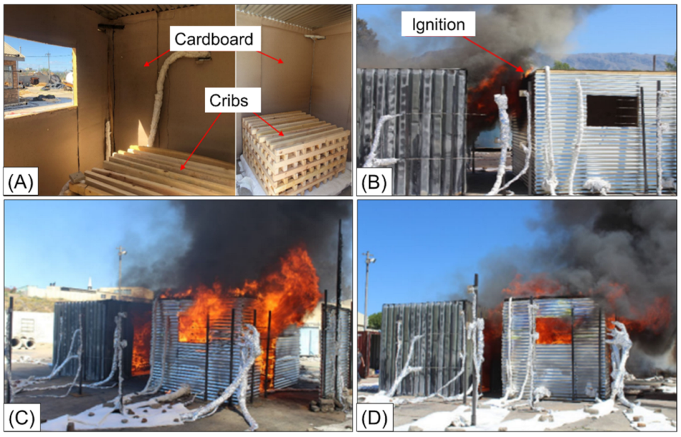
9] to investigate the effect of separation distance on fire spread rates between the dwellings. In the experiments two dwellings were placed adjacent to each other and the separating distances between them were varied as shown in
Figure 1, along with the varying of parameters such as window position and wall lining material. The full-scale steel-clad dwellings [
9] had a floor area identical to the ISO 9705 room of 3.6 m × 2.4 m, but with a height of 2.3 m (rather than 2.4 m). The dwelling of fire origin, denoted as ISD1, had a single door opening of 2.05 m (height) × 0.85 m (width) on the longer side. The other dwelling denoted as ISD2 had two openings, a door of 2.05 m (height) × 0.85 m (width) on the 3.6 m long side and a window of 0.6 m (height) and 0.85 m (width) on the 2.4 m long side 1.25 m from the ground level (sill height). The ISDs were positioned in such a way that the door of ISD-1 was facing the backwall of ISD-2, and the dwellings during these experiments were separated by 1 m and 1.75 m, and the same can be seen in
Figure 1.
During the experiments, the ignition wood crib in ISD-1 was ignited, and the impact of flame and heat flux emanating from ISD-1 on ISD-2 was analysed. Parameters such as heat release rate (HRR), gas temperatures inside the compartment at various levels using thermocouple (TC) trees, surface temperatures on the claddings, velocity and temperatures at the openings, and incident heat flux were measured. Each dwelling was loaded with approximately 130 kg of fuel consisting of wood cribs and cardboard lining contributing to a surface-controlled heat release rate of approximately 6.7 MW. The maximum recorded HRR for ISD-1 and ISD-2, based on mass loss data, were 6.5 MW and 8.4 MW, respectively. It was found, as expected, that an increase in separation distance from 1 m to 1.75 m decreased the incident heat flux from ISD-1 onto ISD-2 from 33 kW/m2 to 27 kW/m2. Consequently, the ignition time of ISD-2 also increased exponentially as the separating distance increased, consistent with fundamental radiation equations.
Figure 1.
The effect of separation distance between informal dwellings on fire spread rates (
A) Interior and wood crib arrangement; (
B) ignition from ISD1 to ISD2; (
C,
D) fire spread between dwellings at 1 m and 1.75 m [
9].
Figure 1.
The effect of separation distance between informal dwellings on fire spread rates (
A) Interior and wood crib arrangement; (
B) ignition from ISD1 to ISD2; (
C,
D) fire spread between dwellings at 1 m and 1.75 m [
9].
2.2. Triple Dwelling FSE Focussing on Separation Distance
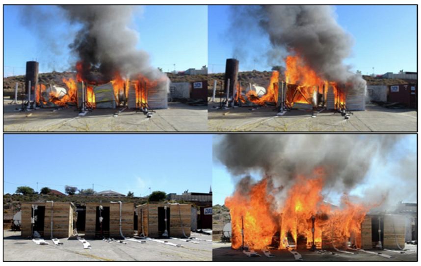
Similar large-scale studies on ISDs were conducted to understand the fire spread between multiple steel and timber-clad informal settlement dwellings (ISDs) [
7] as shown in
Figure 2. Two full-scale ISD burn experiments were conducted with (a) three ISDs clad with steel sheeting and (b) three ISDs clad with timber. The heat fluxes and temperatures of both experiments were compared (steel-clad vs. timber-clad) to understand the effect of cladding materials on fire spread. The dwelling size used was 3 m × 3 m × 2.3 m with a door of 0.86 m × 2.03 m and a window of 0.6 m × 0.6 m. To limit the amount of setup variability and number of parameters studied in this paper the RSEs developed below are based on the rectangular 2.4 m × 3.6 m floor plan rather than the 3 m × 3 m floor plan. The paper addressed fire spread behaviour in between different ISDs and primarily focused providing a technical basis with regards to experienced temperatures, fire spread rate, heat fluxes, etc. steel-clad and timber-clad dwellings had similar internal temperature profile. The heat fluxes from timber-clad dwellings ranges from 140 kW/m
2 to 240 kW/m
2 which approximately 1.5 times higher than steel-clad dwellings. The cardboard linings for timber-clad dwellings had reduced effect on fire spread because of combustibility of cladding itself. During full developed phase, the HRR in the steel-clad dwellings was ventilation controlled, whereas for timber-clad dwelling, HRR was limited by the fuel availability. Fire spread times (from the start of flashover in the first dwelling to the end of flashover in the last dwelling) for both experiments (timber and steel) ranged between 4 and 9 min. The paper concludes that the timber-clad dwellings are clearly a higher risk to fire spread defines a critical separation of 3–5 m, based on the studied geometry and fuel specifications, to prevent fire spread between dwellings.
2.3. Twenty Dwelling Large-Scale Experiment
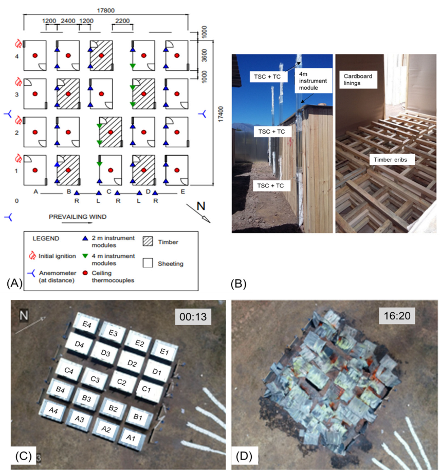
This experiment aimed at understanding the settlement-scale fire spread behaviour of informal settlement dwellings (ISDs) [
10], using a mock twenty dwelling test settlement. The dwellings were built as simple timber cross member assembled from 48 × 48 mm square pine sections and cladding was attached to these cross members. There were fourteen steel-clad dwellings of 0.5 mm galvanised steel sheets, and the remaining six dwellings were clad with 14 mm thick timber planks. The roof panels of all dwellings were provided with 0.5 mm galvanised steel sheeting. A video of the experiment can be viewed at
https://youtu.be/kkXr6ueakAU (accessed on 1 May 2021).
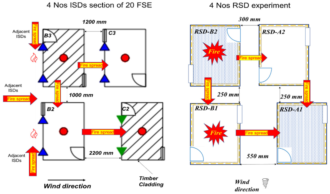
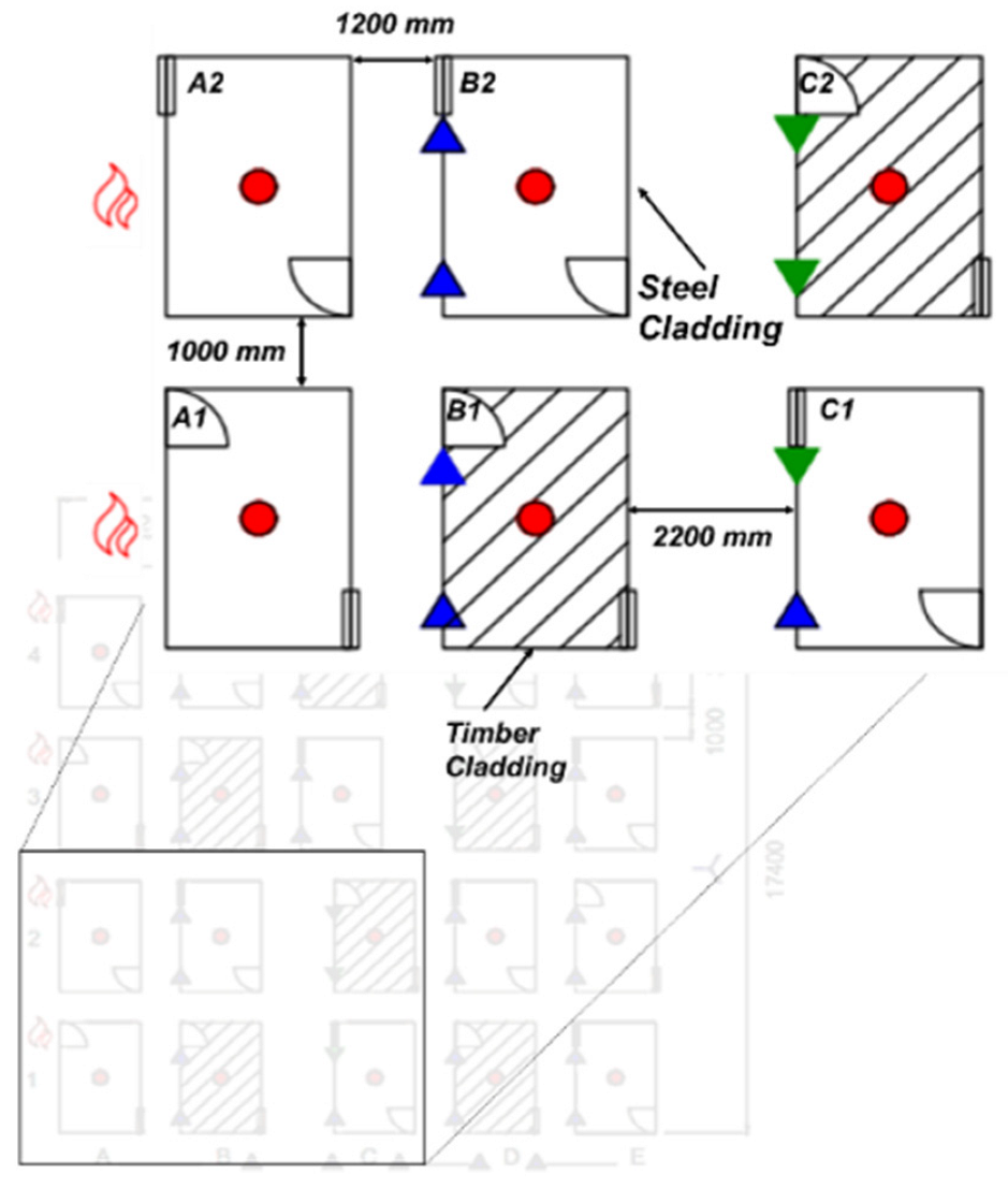
All dwellings were constructed with a floor area of 3.6 m × 2.4 m (length × width) and a height of 2.2 m. The mock settlement consists of four dwellings spaced 1.0 m apart in a row and there were five rows of dwellings spaced 1.2 m apart, except for four instances where the spacing was 2.2 m. Doors or windows were located on the left-hand or right-hand side of each longitudinal dwelling wall (i.e., not on the short edge), and alternated to cover door–door, window–window, window–door, and door–window facing wall configurations across transverse alleyways as in
Figure 3. Interiors of the dwellings were covered with a cardboard lining to represent insulation of ISDs.
Cribs from South African pine were chosen as the primary fuel. Each dwelling was loaded with 450 MJ/m2 of fuel consisting of 1.0 m lengths of the same 48 mm × 48 mm timber arranged into six cribs per dwelling, each stacked as seven alternating transverse layers of four timber lengths.
A ‘‘fire line’’ scenario was created by simultaneously igniting four dwellings in a row, and then allowing the fire to propagate through the settlement to replicate fire disasters involving large numbers of homes. Results highlight the critical hazard posed by the proximity of neighbouring dwellings (1–2 m), with the wind playing a primary role in directing and driving the spread process. Even with a mild wind speed of 15–25 km/h, the fire spread through the entire mock settlement within a short 5 min period. Following ignition of a given dwelling, flashover is reached very quickly, with the temperatures reaching more than 1000 °C within 1 min, and downwind neighbour structures igniting in less than a minute thereafter. The results suggest that multi-dwelling effects are not dominant in these types of fires but may become meaningful at a larger scale when branding and topography play a role.
Figure 3.
Full-scale fire test on 20 informal dwellings. (
A) Experiment layout, (
B) instrumentation and fuel load arrangement, (
C) aerial image of fire experiment soon after ignition, (
D) image of fire experiment at 16 min 20 s [
10].
Figure 3.
Full-scale fire test on 20 informal dwellings. (
A) Experiment layout, (
B) instrumentation and fuel load arrangement, (
C) aerial image of fire experiment soon after ignition, (
D) image of fire experiment at 16 min 20 s [
10].
3. Reduced Scaled Modelling Methodology
3.1. Scaling Considerations for Ignition
When developing RSEs it must be considered what parameter and behaviour should be captured through an experiment, as discussed above. For informal settlements the occurrence of fire spread between dwellings is of primary concern such that interventions for reducing spread, improving home layouts or enhancing construction materials used can be identified, whilst also enhancing data available for the development of numerical models. Ignition of dwellings typically occurs due to (1) radiation onto target dwellings exceeding critical heat fluxes (or flux-time products for time-variable fluxes), or (2) flame impingement where flames are able to impart sufficient flux to cause ignition. The two mechanisms cannot easily be separated and always occur simultaneously. The first item ignited is typically a material such as cardboard, curtains, plastic linings, and timber cross members in its vicinity due the energy emitted by the flames above openings, cladding, and from fire within a dwelling (i.e., openings).
In terms of quantifying fluxes: (1) the total radiative flux received by a dwelling is based on the summation of the radiative flux emitted from a burning dwelling’s flames (i.e., above openings), openings and sidewall cladding (especially for heated steel or burning timber): . The radiation received from each is a function of the view/configuration factor, , temperature difference of the emitter and receiver to the fourth power, , and emissivity of each component, . (2) For localised flame impingement there is convective and radiative transfer to the target surface responsible for piloted ignition of already pyrolysing combustibles, which is dependent upon flame length and flame height.
From the equations above, it can be observed that even if the only criterion that one seeks to match in RSEs is whether ignition occurs, it is a task involving multiple parameters that interact in a non-linear manner. In some ways scaling radiation is easier, provided that temperatures of emitting items are known, as equations can be more readily applied. The scaling of flame length and height, along with the flux that a smaller flame imparts, is a greater challenge. Hence, this work seeks to identify what can, and cannot, be accomplished through scaling methodologies to capture spread behaviour.
3.2. Wind Considerations
Following discussions that flame behaviour and impingement is important, in real informal settlement incidents wind plays a significant role in directing fire spread. Due to climatic conditions, local terrain, densely packed dwellings and even vegetation there is often significant turbulence and gusting of winds. Furthermore, wind movements around dwellings can lead to localised changes in wind direction and speed. This leads to wind causing flames to pulse from dwelling to dwelling and fluctuate from side to side. Ignition can occur at any time, even during a short-lived wind direction reversal. Such behaviour is extremely difficult to capture. In the tests conducted wind effects were included by testing outside and measuring the average wind speed. However, increased wind speeds may not always lead to increased spread as they can also lead to convective cooling of dwellings, thereby causing increased times to ignition, rather than more rapid ignition, even under favourable wind direction conditions.
3.3. Reduced Scale Dwelling Design and Methodology
The RSEs designed in this paper were based on Froude scaling technique. The scaling correlations of dimensional groups from the conservation equations are based on Quintiere [
19]. In this work, the geometry of the Reduced-Scale Dwellings (RSDs) is based on the full-scale ISD experiment introduced above. The RSDs are geometrically scaled according to respective geometric ratios and the vents (doors and windows) are scaled based on ventilation factor scaling according to
as used by Bryner et al. [
20] where ‘s’ represents the scaling ratio (i.e., ¼ as discussed below). For the RSEs, the HRRs were scaled according to
and subsequently the average burning times were scaled according to
. Wood cribs were used as fuel to represent the anticipated fire load. The design details of the wood cribs for RSEs are discussed in the sections that follow. The steel sheets are considered a thermally thin material (Biot number in order of 10
−2 < 0.1), with a thickness of 0.6–0.8 mm, and the thermal properties can be assumed to be homogeneous. This property allows the thickness of steel sheets to be scaled geometrically and the influence of thermal inertia (κρc) to be neglected.
In this research informal settlement dwellings (ISDs) at ¼
th scale of the full-scale experiment (FSE) were constructed for the reduced scale experiments (RSEs). The scaling principles, methodology, and scaling correlations are described in [
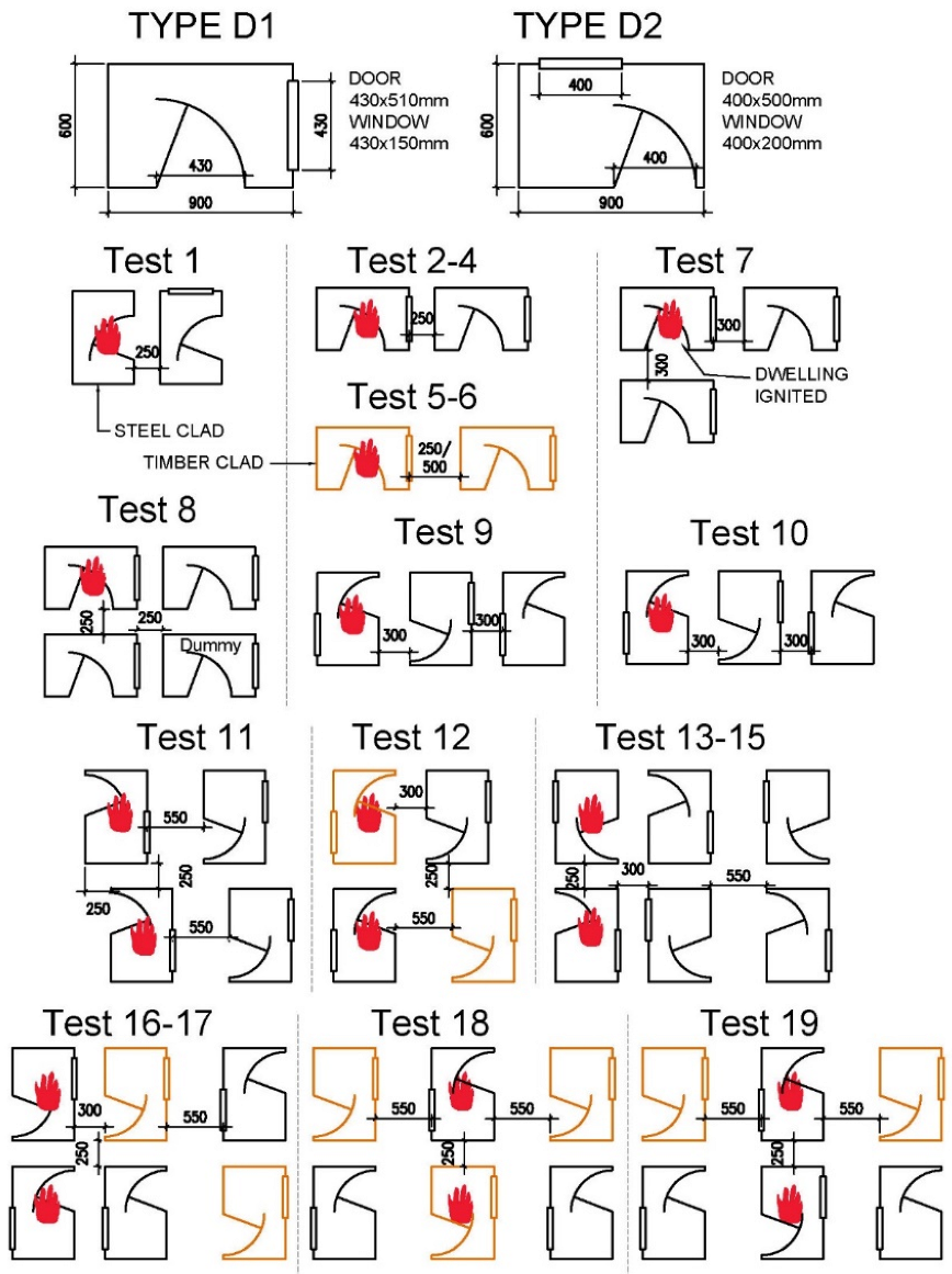
17]. In this experiment series, two types of reduced-scale dwellings (RSDs) were constructed: (a) Type “D1” with internal dimensions of 0.9 m (length) × 0.6 m (width) × 0.58 m (height) to replicate the double dwelling setup of Cicione et al., and (b) Type “D2” with internal dimensions of 0.9 m × 0.6 m × 0.55 m but also with different ventilation details to represent the 20-dwelling setup of de Koker et al. Each RSD had a door and a window opening which is shown in
Figure 4. The dimensions of the openings of full-scale dwellings and RSD along with their associated ventilation condition are provided in
Table 1.
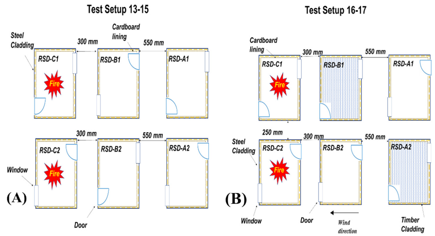
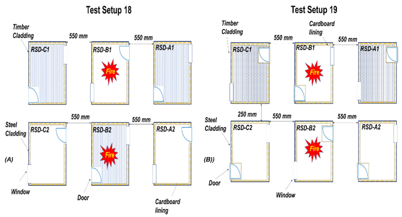
Figure 4.
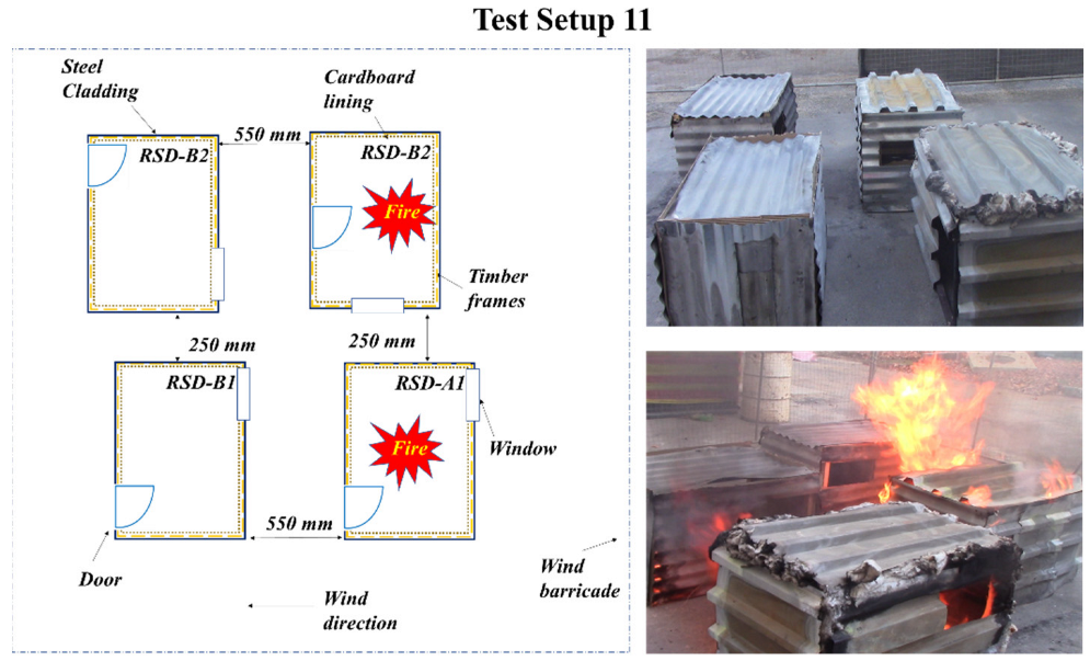
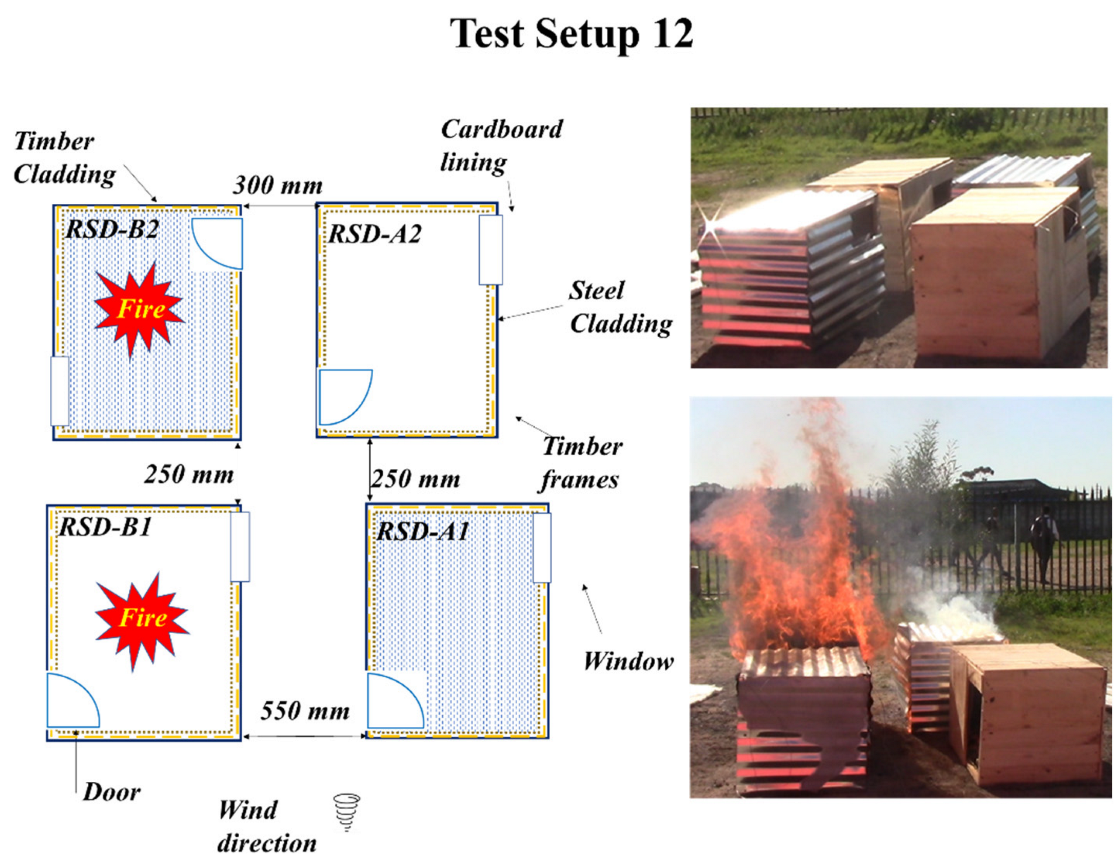
Pictorial representation of 19 test setups showing dwelling layouts (top) and test setups. Steel-clad dwellings are shown in black, timber-clad dwellings in brown and ignited dwellings with the fire symbol.
Figure 4.
Pictorial representation of 19 test setups showing dwelling layouts (top) and test setups. Steel-clad dwellings are shown in black, timber-clad dwellings in brown and ignited dwellings with the fire symbol.
Table 1.
Dimensions of ¼th scale reduced scale dwellings.
Table 1.
Dimensions of ¼th scale reduced scale dwellings.
| Scale | Parameter | Dimensions (m) | Total Opening Area
(m2) | Total Opening Height
(m) | Total Ventilation Factor
(m3/2) | Ventilation-Controlled HRR
(kW) |
|---|
| Room | Door | Windows |
|---|
| Full Scale-1 | Length | 3.60 | - | - | 2.253 | 1.722 | 2.956 | 6029 |
| Width | 2.40 | 0.85 | 0.85 |
| Height | 2.30 | 2.05 | 0.60 |
| “D1”—RSD Type-1 | Length | 0.90 | - | - | 0.282 | 0.430 | 0.185 | 498 |
| Width | 0.60 | 0.43 | 0.43 |
| Height | 0.58 | 0.51 | 0.15 |
| Full Scale-2 | Length | 3.60 | - | - | 2.240 | 1.657 | 2.884 | 7785 |
| Width | 2.40 | 0.80 | 0.80 |
| Height | 2.20 | 2.00 | 0.80 |
| “D2”—RSD Type-2 | Length | 0.90 | - | - | 0.280 | 0.471 | 0.192 | 519 |
| Width | 0.60 | 0.40 | 0.40 |
| Height | 0.55 | 0.50 | 0.20 |
3.4. Reduced Scale Experiment Configurations
The RSDs in these experiments were varied in terms of the cladding materials (14 mm timber strips or 0.5 mm galvanised steel sheet), type of cross member (25 mm × 25 mm timber or steel angles), and positions of windows and doors. All the RSDs were provided with a 1.5 mm thick cardboard layer on the inner side to replicate combustible thermal insulation often used for ISDs. The presence of cardboard significantly influences fire dynamics within dwellings.
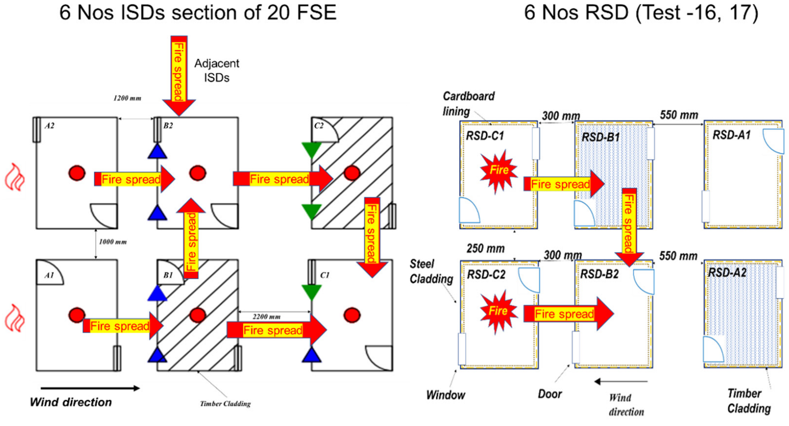
An RSD configuration in which the fire spread is observed from the side i.e., from left RSD to right RSD, it is defined as “lateral” and if fire spread is observed from the front door to backwall of a RSD, then it is considered as “longitudinal. The wind directions during experiments were: (1) “favourable” meaning wind that aids fire spread, (2) “opposing” refers to a wind direction that opposes fire spread, (3) “cross wind” means a wind direction that is approximately perpendicular to fire spread, and (4) “circular” refers to a fluctuating wind does not have a specific direction, or which changes its direction all the time. Experiments were conducted outside meaning that it was not possible to control the wind speed and direction. The flashover time during the test was determined by the ceiling temperature of RSDs exceeding 600 °C or the time when the flames were visible through the openings, whichever was observed first. The experimental fire time of an RSD was considered to be a duration between ignition until collapse or until fuel burn out. Ignition is defined based on either observations or a distinct increase in temperature above ambient evidenced by thermocouple data.
Table 2 lists the testing regime which includes all experiments, relevant variable factors that can affect the fire spread in-between the dwellings, and a unique test identification number consisting of all the data provided in the table. The experiment ID is unique for all test setups to identify dwellings arrangement to assist the reader in sections that follow. For example, “1-2D-S-250-F” represents the test number (e.g., 1); number of ‘D’wellings involved (2D to 6D); type of cladding (‘S’teel or ‘T’imber); spacing of RSDs (e.g., 250 mm); and wind condition (‘F’avourable, ‘O’pposing, Crosswind ‘K’, ‘C’ircular, not applicable or negligible ‘/’).
Figure 4 provides the pictorial representation of the 19 setups with unique RSD ID that are provided on the top of each test setups. In Experiment 8, a dummy dwelling was included which had no fuel load or cladding, and simply served as a flame barrier.
3.5. Fuel Source
From the previous work on ISDs, it was seen that the fuel load in an informal dwelling range between 400 MJ/m
2 to 2000 MJ/m
2 [
4]. Although the fuel load range varies significantly, fires in these dwellings are typically ventilation controlled and they collapse before the fuel burns out, indicating the role of other factors that could play a substantial effect on fire dynamics inside an ISD. For all RSEs, the cross-sectional (
) dimension, number of stick levels (
) of wood cribs were obtained by scaling according to
and
, respectively, whereas the length of each stick and number of sticks per level were changed to obtain the desired HRR. The HRR (Q) of the cribs were calculated as per [
21].
In this work, untreated and kiln dried wood cribs from South African pine were used as the fuel. The density of wood used for the cribs was approximately 580 kg/m
3, the heat of combustion was Δ
Hc = 22.5 MJ/kg as measured in a bomb calorimeter, and the moisture content was less than 12%. There were three different fuel loads based on the different sizes of the wood cribs used in the experiment that are listed in the respective sections. The maximum surface-controlled heat release rate of wood cribs used in this experiment series was 520 kW (21 mm × 21 mm × 450 mm × 48 Nos), 402 kW (25 mm × 25 mm × 500 mm × 30 Nos), and 536 kW (25 mm × 25 mm × 500 mm × 40 Nos). Due to the limited availability of timber fuel the member sizes slightly vary between tests (21 mm vs. 25 mm). The ventilation controlled HRR for each RSD is provided in
Table 1. A timber cladding of thickness 14 mm was used in the experiment, which had a density of 542 kg/m
3 and the heat of combustion of 18.1 MJ/kg as measured in a bomb calorimeter.
3.6. Instrumentation
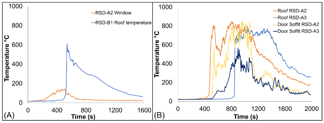
K-type (1.5 mm tip diameter) thermocouples were used as the primary device for measuring temperature. Each RSD had four thermocouples, two placed at 5 mm below ceiling, one at window and door soffit. The measurements of the experiments were recorded with a data logger at every 1 Hz. The instrumentation layout of the experiment is depicted in
Figure 5. Videography and photography were primary evidence to trace the fire spread patterns. The video cameras were placed at multiple angles to capture all moments of fire spread.
5. Conclusions
This paper investigated fire spread using reduced scale dwellings at 1/4th of full-scale informal settlement experiments. The objective of the study was to identify the impact of factors such as cladding material, wind current and separation distance. The study also investigated the relevance of previous multiple-dwelling full-scale experiments in reduced scaling of informal settlement dwellings. The study involved fire spread between two, three, four, and six sets of reduced scaled dwellings with various orientations, separation distances, and cladding materials. Although primarily flame impingement, and secondarily heat flux, are responsible for fire spread to a greater extent, burning remnants from a collapsed dwelling have potential to ignite a new dwelling.
The direction of wind current plays a crucial role in directing flames and driving heat fluxes in both FSEs and RSEs. An optimum wind speed can aid in faster fire spread between the dwellings. However, a strong favourable wind current may also increase the heat losses in the burning RSDs, leading to no effective fire spread to adjacent rows (Test 14), as discussed in
Section 3.2. In some instances, the flames were also seen going over the RSDs instead of hitting the roof panel. Wind can become a dominant factor to fire spread for inter dwelling spacing above 300 mm. Although, wind direction and speed measured at the beginning of each test fluctuations in wind current during most of the test was visible. Since this factor is so dominant, it will be beneficial to conduct such experiments in a wind tunnel in the future where the wind speed can be regulated. Additionally, capturing localised wind effects in between rows of dwellings can support the predication of fire spread and the pulsating behaviour of flame length and flame heights emerging from the openings.
The possibility of ignition is further increased due to the availability of timber cross members (Test 8) and combustible lining inside the dwelling walls. The exposed combustible cross members in the event of fire become involved in fire in the early stage, and they also contribute to fire spread to other combustibles inside the dwelling. The dwelling with higher fuel tends to have longer burning time. A dwelling is likely to be ignited as the increased burning time enhances the devolatilisation process and flame impingement due to longer exposure time. In addition, timber-cladded dwellings increase the risk of ignition in the vicinity to substantial level (Tests 5–6). The timber-clad RSDs have a significant impact on spread fire in ISs. They have the potential to ignite all the combustibles in its vicinity even at 550 mm (2.2 m in FSE) and can alter the dynamics of fire spreading despite having opposing wind currents.
The time to flashover in each case was different and deviated up to 100% from the full-scale experimental results, with RSEs typically ranging between 30 s and 180 s depending upon type of test and location of the RSD. The fire spread time between the dwellings increased with an increase in their separation distances, as would be expected. It was seen from the test that the fire spread due to flame impingement through the door opening contributes more than the window openings. The dwelling with windows on shorter side walls has greater fire spread prospects than the dwelling windows on longer back wall. The addition of an opening has negligible impact on fire spread to the adjacent dwelling, but fire spread in type-1,2 RSDs provided different results under the same environmental conditions, proving the influence of the location of openings in a dwelling (test 11).
The average fire spread rate from all 19 RSEs was 0.092 m/min, ranging from 0.007 m/min in Test 3 to 0.27 m/min in Test 17 (FSE—0.137 m/min), which is significantly lower than the range of 1.2–3.6 m/min as found for real incidents and large-scale experiments. The scaled spread rates varied between 0.14 m/min and 0.55 m/min between rows of dwellings, in comparison to FSEs where spread times ranged between 0.167 m/min and 3.6 m/min. This highlights that even though trends, temperatures, and general fire dynamic behaviour can be captured, RSEs cannot currently be used for quantifying spread rates for informal settlement fires, although the occurrence of spread can be captured to a certain degree.
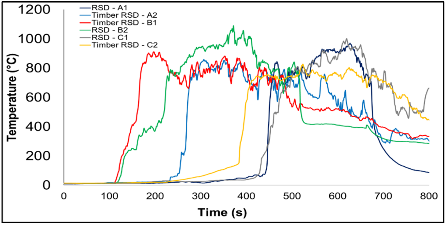
It was observed that the temperature profile for both FSE and RSEs were comparable with similar profiles, but the peak temperature was lower in RSEs than FSE, by around 10–20%. The experiment time from ignition to collapse in all wind conditions and for all RSDs was similar to FSE, but the flashover time in each case was different and deviated from the full-scale experimental results. The time variable in the RSEs was predominantly influenced by wind currents that affected the scaling of experimental time, flashover time, and fire spread rate. However, in few instances where wind current was similar to FSE, time variable was scaled well. Heat flux data in RSEs were not captured which would have further provided details to understand the FSEs and RSEs quantitatively. The results from individual RSEs (test-1–6) provided more comparable results with FSEs than the test with multiple rows, as greater numbers of steps in the flame paths leads to higher levels of uncertainty. It was observed that thermal influence from adjacent section with burning ISDs had great impact on the fire spread, and the same was missing in RSEs. In the experiments with six RSDs, each dwelling was involved in the fire individually and there was no clear distinction of fire spread in different rows.
To sum up, (a) wind, combustible cladding, and separation distance between dwellings significantly influence results. However, (b) the influence of cross member, fuel load inside the dwelling, and type of dwellings also had an impact on fire spread. (c) The comparative results from FSEs and RSEs demonstrate good fire dynamic correlations within the dwellings and in between the dwellings with comparable profiles but (d) have limited correlation to the fire spread rate. The database presented in this work provides a useful basis for enhancing scaling methodologies, but further data are needed before the results can be consistently applied due to the variability encountered. A study on the flame length and flame height emerging from the RSDs with various wind conditions would be beneficial to understand the impact of these parameters on fire spread. By quantifying flame length and height, and developing analytical equations for scaled dwellings, it is hypothesised that the behaviour observed in this paper can be more accurately defined, especially if equations can account for (albeit approximate) wind conditions. It is envisaged that separation distances between dwellings could be specified based on FSEs and RSEs causing the same level of flame impingement on the target dwellings.
Based on the results above, and observations of real informal settlement incidents, more research and testing are needed before large-scale multi-dwelling spread will be predicted accurately. Nevertheless, in future, these experiments can further be extended by changing selected parameters and studying the relative change in the test results using an initial test as a validated benchmark (i.e., all tests conducted at ¼ scale but the relative change in spread rate can be readily quantified by adjusting parameters). Such results can assist in quantifying empirical correlations to predict fire spread mechanisms in relation to multiple informal dwellings with reduced scale experiments considering various parameters. In addition, a numerical simulation can be developed that can predict the influence of numerous variables that can influence fire spread involving a large number of dwellings. As noted above, tests in a wind tunnel would be ideal for more accurately quantifying spread rates and comparing the influence of parameters. This work would serve as preliminary guidance for such a study.


