1. Introduction
The new frontiers of Additive Manufacturing (AM) involve several emerging printing techniques that promise to revolutionize the manufacturing processes in many industrial fields. Indeed, the “additive” approach allows us to create objects with geometries and shapes which are unobtainable by using the classic “subtractive” one. This increased attention toward 3D printing techniques attracts great interest in the development of new printing materials, from polymers and resins to metals and ceramics [
1,
2,
3,
4].
Nowadays, available production technologies make it possible to produce a large variety of powders capable of meeting the requirements of the applications, and generally, to favor the distribution of the beds and the coalescence of the surfaces, powders with a high sphericity are required.
The production of metal powders follows different processes depending on the raw materials used and the properties to be achieved. Atomization is perhaps the most versatile method for producing metal powders. By using atomization, 10 to 105 tons of powders are produced per year, with a size range that can vary from 10 to 1000 µm. The atomization process includes a wide range of technologies used both industrially and experimentally, but the most important ones are certainly gas or water atomization (which alone represent 95% of atomization plants worldwide), and more recently, atomization with plasma.
Plasma atomization is a relatively new process, developed to produce high-purity powders from reactive metals and high-melting-point alloys such as titanium, zirconium, and tantalum [
5,
6]. Plasma atomization allows us to produce fine particles with a highly spherical shape and a low oxygen content. Indeed, the high-temperature plasma (up to 10,000 °C) facilitates the melting of the powder particles, which then turn into little drops that, under the action of their surface tension, can be collected as smaller size particles, often in one-step treatments.
Thermal plasma technologies were already present in the 1990s as high temperature synthesis techniques, in which spheroidization was a secondary effect. For example, Bhattacharjee et al. [
7] used a Direct Current (DC)-transferred arc plasma (20 kW) for the synthesis of Calcia-stabilized Zirconia, demonstrating the suitability of plasma as a high-power source for the synthesis of high-temperature compounds, but at the same time producing spherical powders. Likewise, Rao et al. [
8] used a plant based on DC thermal plasma technology to obtain SiC nanopowders starting from gaseous precursors (SiCl
4 and CH
4). A breakthrough in the application of the technology occurred with the work of Boulos [
9] on the use of Radio Frequency (RF) technology for the synthesis of nanostructured materials but also for the spheroidization of powders.
The production of spherical powders has only recently had a boost towards the fabrication of materials for 3D printing; following the growing interest in AM applications, existing processes and solutions have been directed towards this specific application [
10,
11].
DC technology has not had the same pulse type as RF technology: the use of DC torches finds widespread application in plasma spray, but there are no commercial systems dedicated to spheroidization-like applications on the market. This is because RF flames, while being less energetic than analogous DC solutions, are slower and allow internal axial injection; this determines higher residence times for the powder inside the plasma. The classic DC systems, despite having a higher efficiency and energy density, have much faster flames and external injection of the powders. However, thanks to the recent progress made in the torch manufacturing technique, interest in the new DC-based torches is becoming concrete. In fact, DC plasma systems offer, apart from higher energy densities than RF systems, greater “scalability”. For the purposes of scale-up of processes, the power of modern DC arc plasma torches reaches 3–5 MW with a duration of up to 103 h, while the power from existing RF plasmatrons does not exceed 1 MW. Finally, producing 1 kW of power with RF and MW systems costs about three-times the price spent using DC arc torches. These new DC systems, therefore, appear to be interesting due to their high energy efficiency and can be used for the realization of high-temperature processes on an industrial scale.
Indeed, there are few scientific papers on the production of spherical particles using DC plasma in the literature, particularly for metals [
12,
13,
14,
15,
16]. Itagaki et al. [
17] had a good degree of spheroidization in SS316L steel (commercial powder with irregular shape, average diameter 38 microns, obtained by water atomization) with experimental tests using DC plasma between 9 and 17 kW. A good spherical powder (>80%) was already obtained at 9 kW, even if higher powers were needed to treat the powder fraction with a diameter larger than 50 μm. At a higher power (17 kW), however, the greatest presence of nano particles was recorded.
Products made of SS316L are widely used in industry and everyday life, and 3D-printed SS316L pieces will, therefore, find a wide range of applications. Micron-sized spherical stainless steel powders (SSPs) have specific characteristics such as a low melting point, good toughness, high corrosion resistance, high density, and low cost. SSPs are considered to be one of the best candidates for AM systems [
18,
19].
Within this framework, the present paper will describe the results obtained from plasma processing SS316L powders, conducted in a DC thermal plasma plant with the aim of obtaining spherical powder particles, thus demonstrating the feasibility of using DC plasma treatments to produce high-grade powders from irregularly shaped mixtures. The effect of the plasma power and the powder feed rate on the characteristics of the obtained particles were investigated. The powders were characterized in terms of morphology, crystalline phases, elemental composition, particle size distribution, and flow properties both before and after the plasma processing.
2. Materials and Methods
Two sets of commercial SS316L powders provided by Thermo Fisher Scientific GmbH, (Kandel, Germany) were used for the experimental work: SS316L < 325 mesh (44 microns), referred as A, and SS316L < 100 mesh (149 microns), referred as B.
The raw powders were processed in a DC thermal plasma plant, which was designed and installed at the ENEA Research Centre of Portici (Italy).
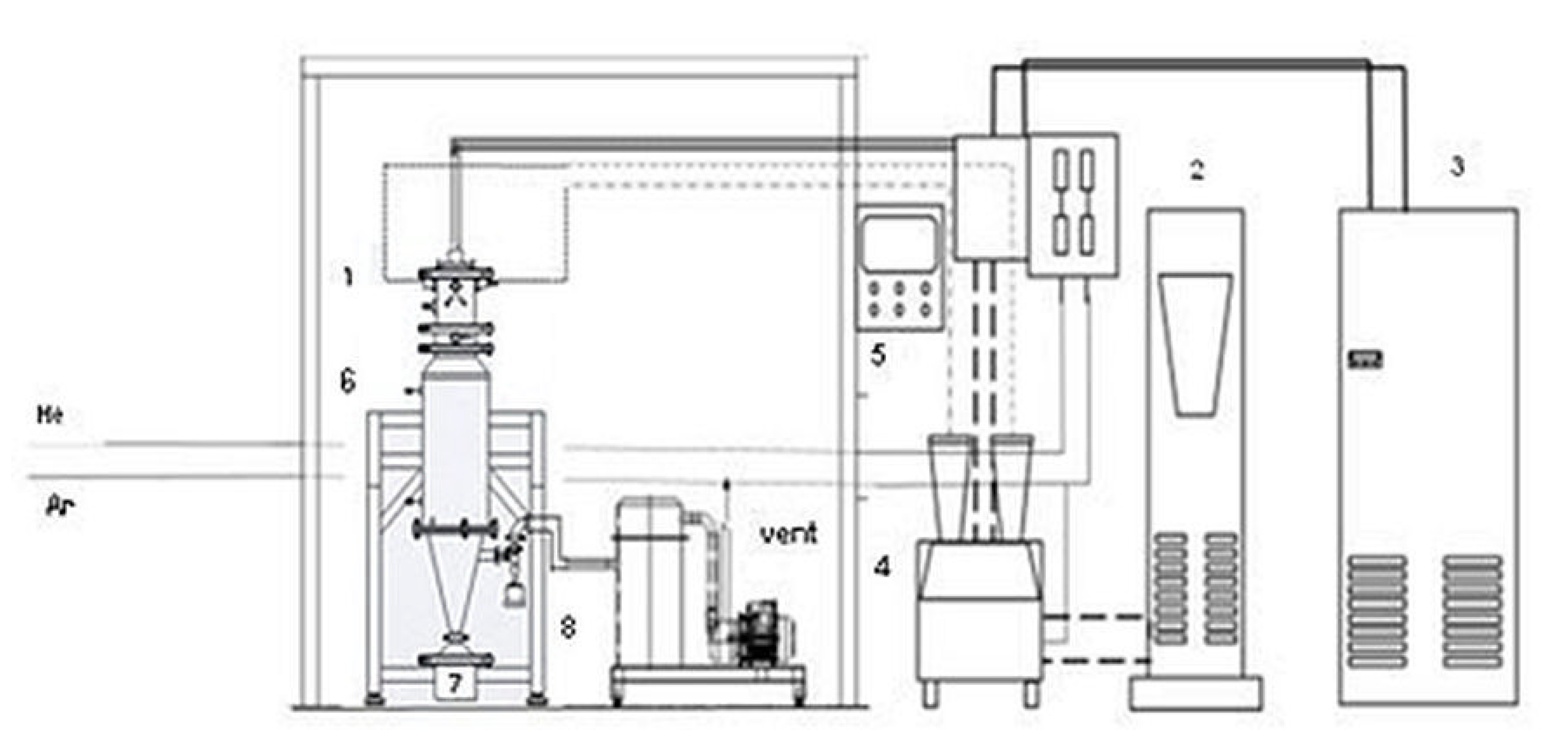
Figure 1 shows a flow sheet of the plant.
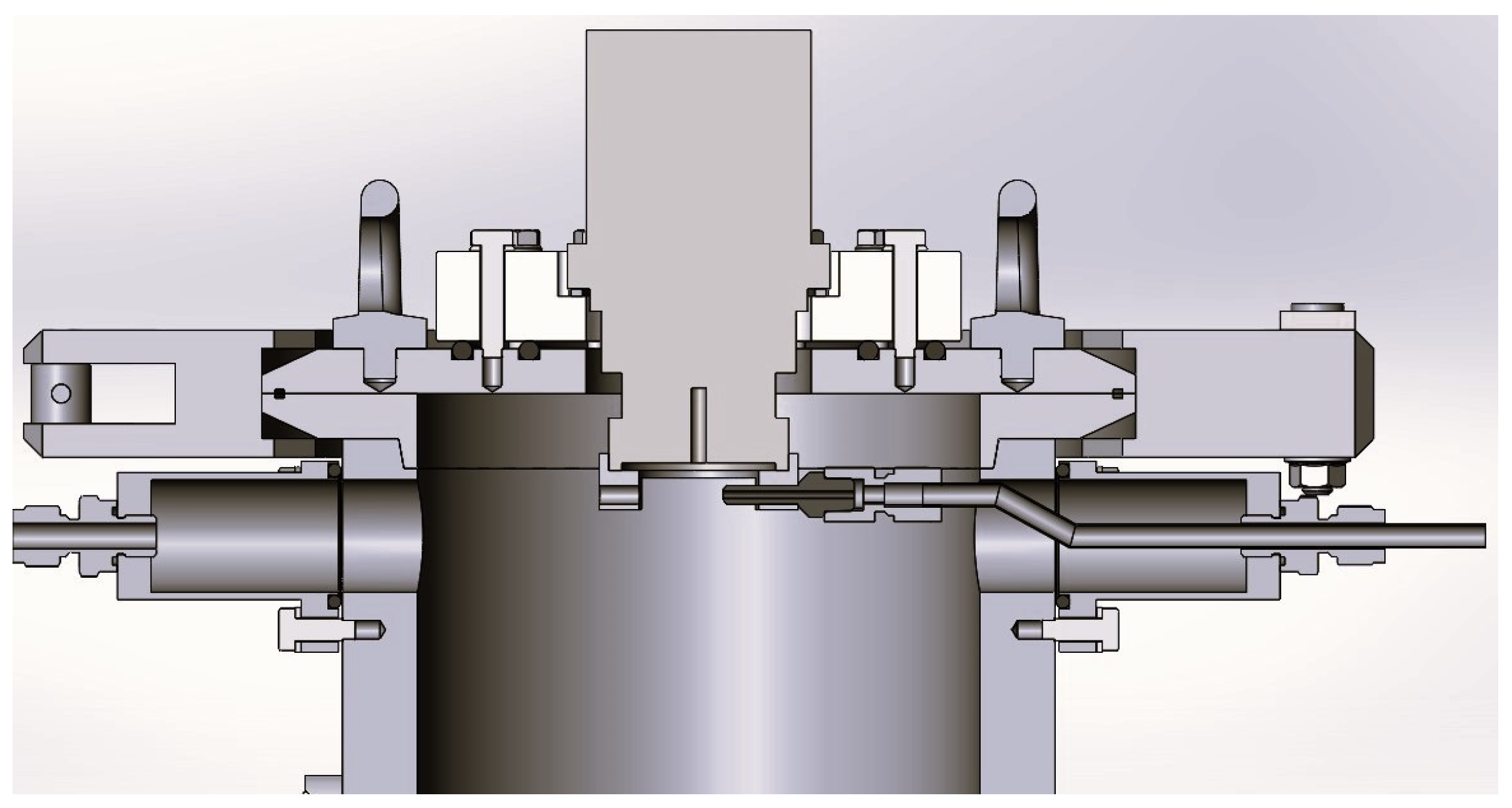
The system comprises a powder feeder system, a DC non-transferred plasma torch (Praxair Surface Technologies F4 model, Fornovo di Taro (Parma, Italy), a power supply (GTV 800 A), a cyclone/bag filter, and a dry scroll pump for vacuum. The plasma operates under a light vacuum (up to 80 kPa). The torch consists of a standard water-cooled tungsten v-shaped cathode and a copper/tungsten 8 mm anode nozzle provided by Praxair Surface Technologies, and it is fitted in the upper part of a jacketed, cylindrical stainless steel reactor of 13 cm inner diameter and 185 cm length, cooled with circulating cold water. The reactor is equipped with a collection tank, where the produced powders are collected along with the unreacted materials. At the top of the reactor, one nozzle feeds the powder directly into the plasma flame (
Figure 2). The nozzle has a diameter of 2.4 mm; it is approximately 2 cm away from the center of the flame. A positioning ring at the base of the torch allows the right line up and defines the injection angle (75° in all tests).
The tests were conducted by varying the current value (in the range of 300–654 A) on the PLC to reach the required power; the voltage value was adjusted by the generator accordingly and it is in the range of 31–33 V.
The test was conducted using argon (Ar) as the main gas to light the plasma and helium (He) as secondary gas to improve the flame conditions. Argon was also used as a carrier for injecting the powders. Gas flow rates used for the tests are reported in the tables describing the plasma process parameters (Tables 1 and 4).
After entering the plasma flame, the powders melt at a temperature higher than 10,000 °C; during the process, the smallest particles can evaporate resulting in the formation of fine deposits after cooling. The final products were collected both at the bottom (collection tank) and at the cold wall of the reactor chamber.
Morphological analyses of the samples were carried out using a scanning electron microscope (SEM, Thermo Fisher Scientific “Phenom Pure” with upgrade to Phenom ProX). Energy-dispersive X-ray (EDX) spectral analysis was also used to determine the overall chemical composition of the samples with the Phenom (15 kV). The SEM pictures were used and further processed to measure the particles’ dimensions. Image processing and calculation were carried out in the image editor “ImageJ” (Software version 1.54g, NIH and LOCI, Wisconsin, WI, USA).
The particle size distribution was calculated using a Laser Diffraction MICROTAC MRB SYNC 3R equipped with system dry dispersion TURBOSYNC.
Phase identification of the samples was performed by X-ray diffraction (XRD) analysis with a X’Pert MPD diffractometer using nickel-filtered Cu Kα radiation in the range of 2θ = 20°–80° with a 0.050° step width and a 5 s counting time for each step. Powder phase identification was obtained comparing the diffraction pattern with SS316L Joint Committee on Powder Diffraction Standards (JCPDS) cards No. 33-397 and 34-396 [
20].
The flowability of the powders was evaluated by applying the ISO 4490-2018 standard, which is based on the Hall and Carney flowmeter method. The measurements were conducted using the POWDERFLOW kit from Carpenter Additive. According to the standard protocol (ASTM B213), 50 g of powder was timed passing through the funnel and the result is given as seconds/50 g.
3. Results
The experimental tests for powder A were conducted by varying the plasma power in the range 9–17 kW and keeping the other parameters constant (pressure, gas flow rate, and powder feeding rate), as shown in
Table 1. The last column of the table refers to the process yield, calculated as the weight percentage of the input powder/collected powder ratio.
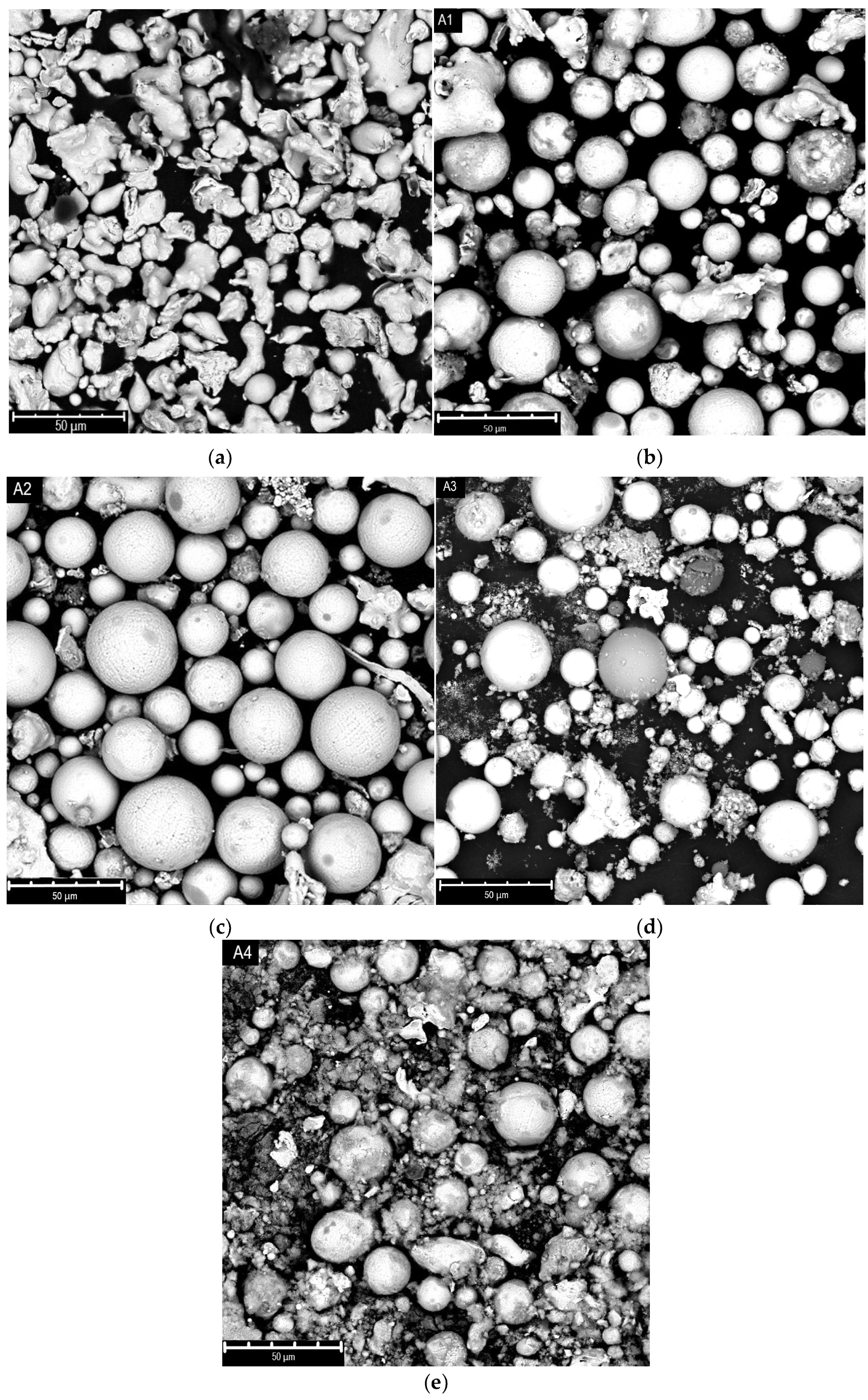
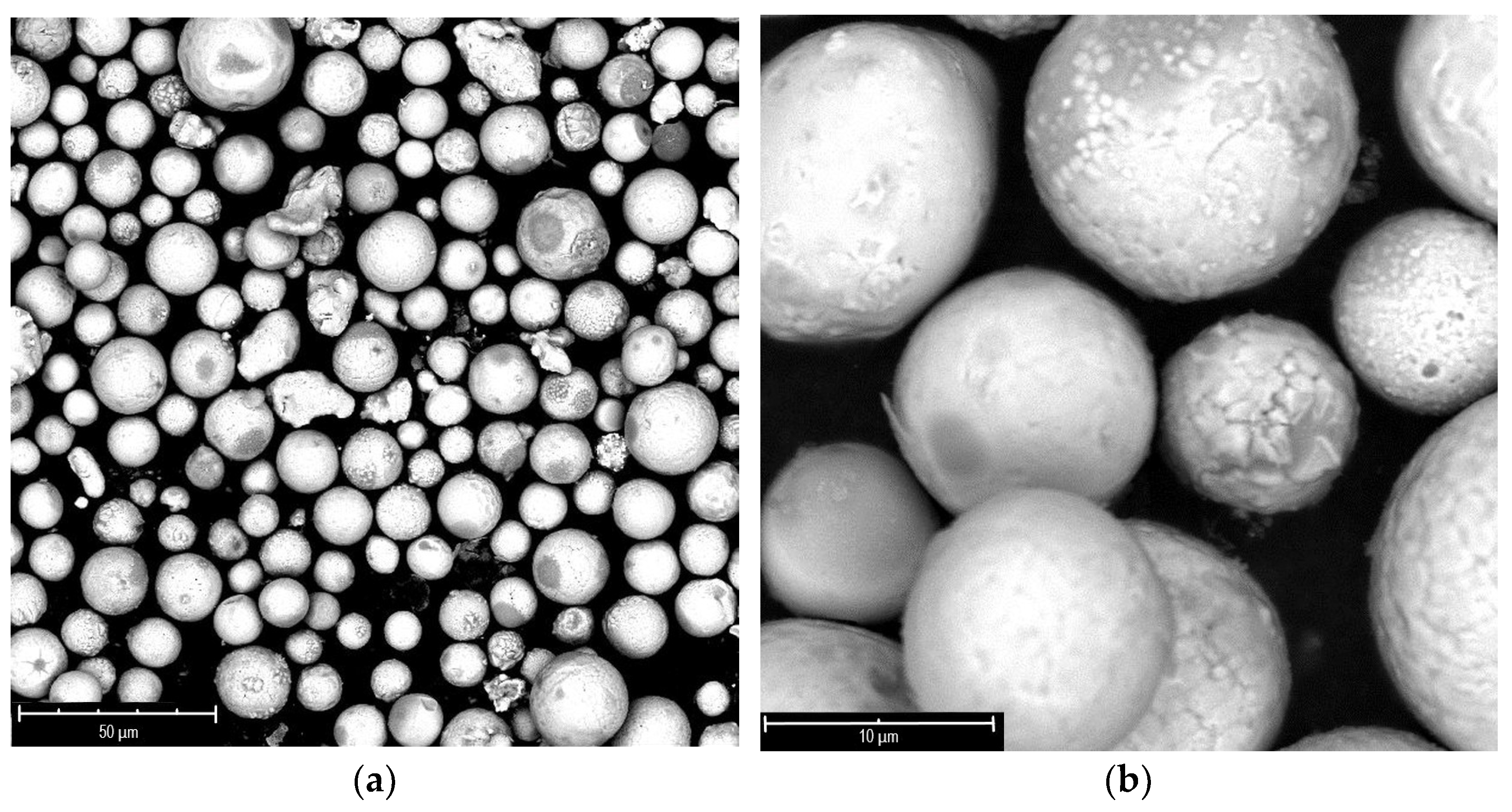
Figure 3 shows the SEM images of the “A” samples, both raw (a) and after plasma treatment (b–e). The raw powder presents irregular shaped particles, with a quite broad dimensional distribution centered at 44 microns. Alongside aggregates of higher diameters, up to over 60 microns, very small particles of only a few microns are present.
The SEM images show that, already at 9 kW of power, a large number of spheres are visible; the spheroidization rises at higher power up to 12 kW. In the meantime, the formation of nanoparticles together with spheroidization appears at 15 kW. Nevertheless, at the maximum power (17 kW), the formation of a huge quantity of nanoparticles is evident, probably due to the extensive evaporation of the material.
This evidence can be explained considering that, during the process, the injected particles absorb energy from the plasma, and if the energy is enough, they melt; once out of the plume, the particles start to cool down, and due to the action of surface tension forces, their shape becomes spherical. If the absorbed energy exceeds that required for melting, the particles evaporate; in this case the rapid quenching of the reactor determines their recondensation in the form of nanoparticles [
17].
In the A-type trials, all the powders were collected on the reactor wall.
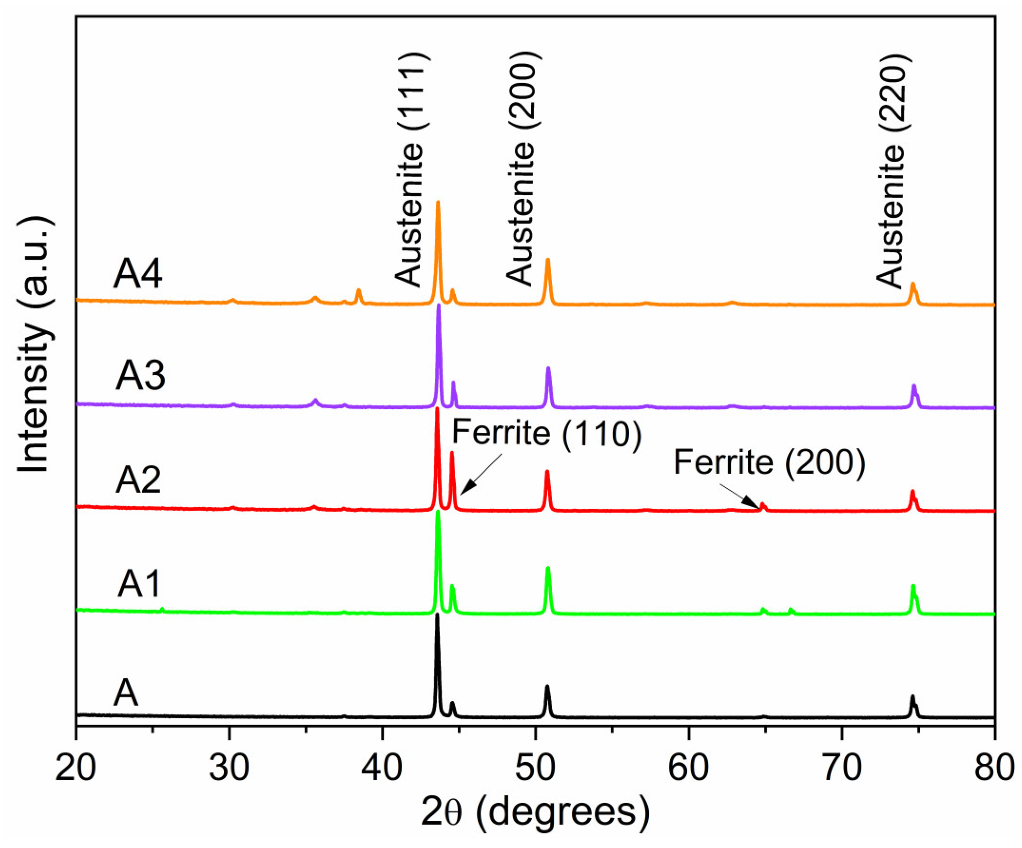
The XRD patterns of the samples before and after the plasma treatment are reported in
Figure 4.
The raw A powder mainly exhibits fully austenitic structures (face-centered cubic structure) with peaks at 2θ values of 43.6°, 50.8°, 74.8° corresponding to (111), (200), (200) reflections, respectively. The ferrite phase (body-centered cubic structure) is present in small quantities at 2θ values of 44.6° and 64.8° due to (110) and (220) reflections, respectively.
Also, the processed powders show an austenitic structure in the main phase, alongside an appreciable amount of ferrite. The transformation between austenite and ferrite takes place during the cooling phase (rapid quenching) of the particles. The maximum conversion is evident in the powder treated at 12.4 kW (test A2 in
Table 1).
Other diffraction peaks of minor intensity are also observed at 2θ of 30°, 35°, 38°, 57°, and 63°, attributable to oxides formed during the annealing of the commercial steel or more generally due to the oxidation of the products (mainly Fe
2O
3, Fe
3O
4, or FeCr
2O
4 [
21,
22]).
Generally, the oxides’ formation, which can result during the cooling phase, is attributed to the presence of nanoparticles, which tend to oxidize [
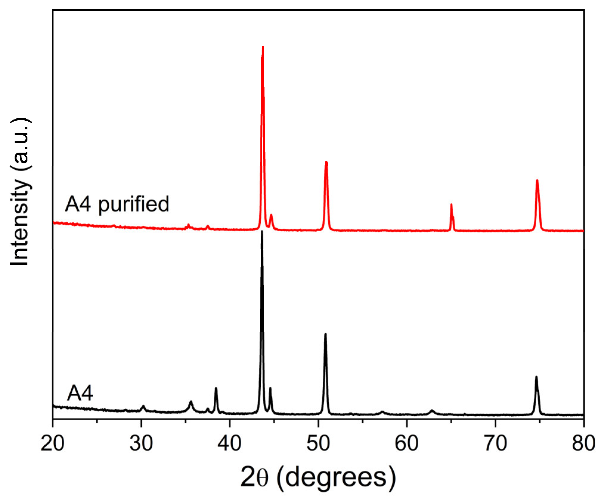
23]. Indeed, the powder processed at 17 kW (test A4) exhibits higher diffraction peaks corresponding to oxide structures than the other powders, confirming the relevant nanoparticles content. A further purification treatment was applied to the powder through a sonication step, at room temperature, in ethanol, which greatly improved the purity of the material by removing most of the nanometric deposits, as shown in
Figure 5.
As further confirmation of the effectiveness of the purification step for the nanoparticles, the comparison between the XRD patterns of the A4 powder before and after the treatment shows that the diffraction peaks at 30°, 35°, 38°, 57°, and 63° of 2θ, which occur in presence of Fe
3O
4 or FeCr
2O
4 oxides, are massively reduced after the treatment (
Figure 6).
Table 2 shows a list of the main elements of 316L stainless steel and the weight % composition of powders A, A4, and A4 purified and obtained by EDX analysis. The EDX results show a detectable amount of oxygen in the starting A powder. As expected, sample A4 contains a major percentage of oxygen, due to the presence of nanopowders; after purification, the oxygen content is reduced, reaching a weight percentage similar to that of the starting material.
Although EDX analysis has a higher qualitative value and additional investigations should be performed using quantitative techniques which are not currently available, the results obtained agree with the XRD evidence.
The particle size distributions of the powders before and after the plasma treatment are reported in
Table 3.
The data show that the spheroidized powders’ particle distributions, whatever the processing power, are narrower than that of raw powder, and that, particularly at a processing power of 15 kW, the powder distribution is shifted towards smaller particle size. This trend is equally confirmed by the span, which is an additional parameter used to quantify the distribution width and defined by Equation (1):
where d90 represents the point that the cumulative (from 0 to 100%) undersize particle size distribution reaches 90%, as for d50 and d10. In fact,
Table 3 shows that the minimum span value is registered at 0.9.
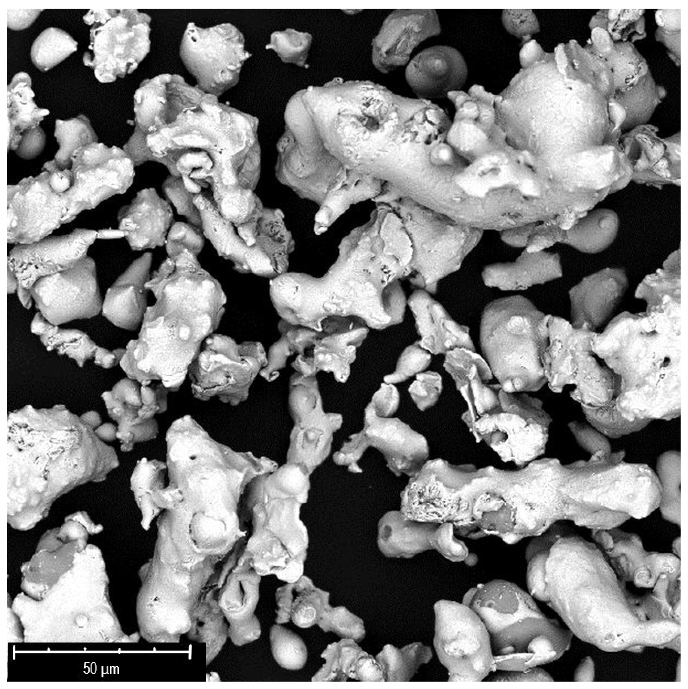
A second experimental test set was conducted on SS316L < 100 mesh (149 microns) powder, called B. This sample, according to the SEM image (
Figure 7), shows irregular-shaped particles and a rather wide distribution of dimensions, with major aggregates of 100 microns along with small particles around 10 microns.
Such a large distribution of dimensions, unlike the previously analyzed powder (SS316L < 325 mesh), suggested the utilization of higher plasma powers.
Table 4 shows the process parameters used for the plasma processing of the B powders.
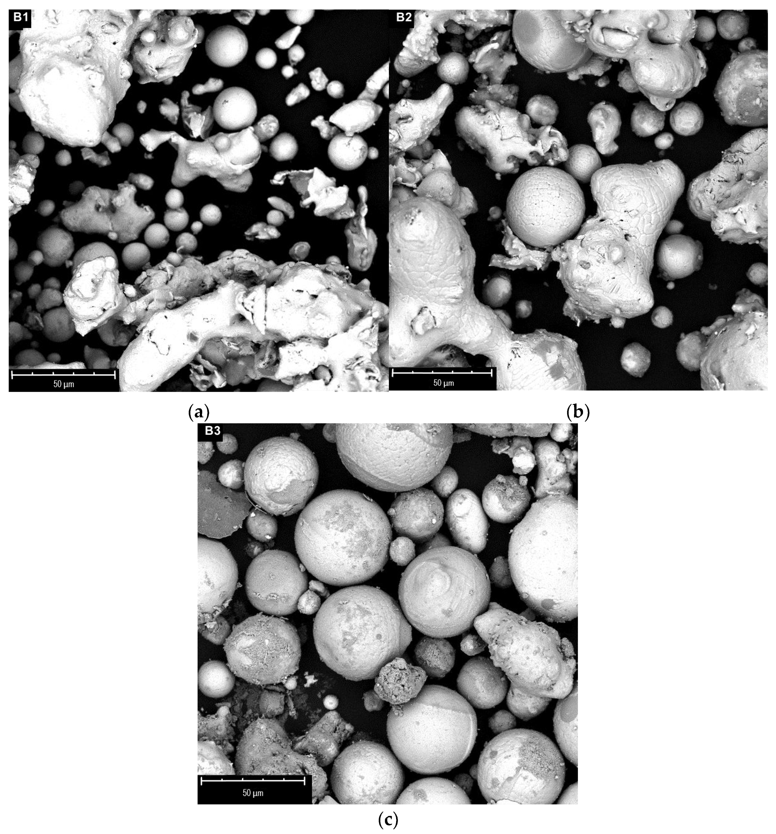
The SEM images of samples B treated under different plasma powers (range 12.5–21 kW) are reported in
Figure 8.
The spheroidization process begins at the lowest power, with the formation of spheres with small sizes (below 30 microns), but the larger particles appear to be only slightly touched by the flame (rounding). The spheroidization degree increases at higher powers, already involving most of the material at 21 kW. By further increasing the power, the formation of an appreciable quantity of nanoparticles is generally observed alongside the spheres, probably due to the vaporization of the smaller size material. This phenomenon is mostly evident in the fraction of material deposited on the cold walls of the reactor. For this reason, higher plasma powers do not seem to be particularly advantageous for the process.
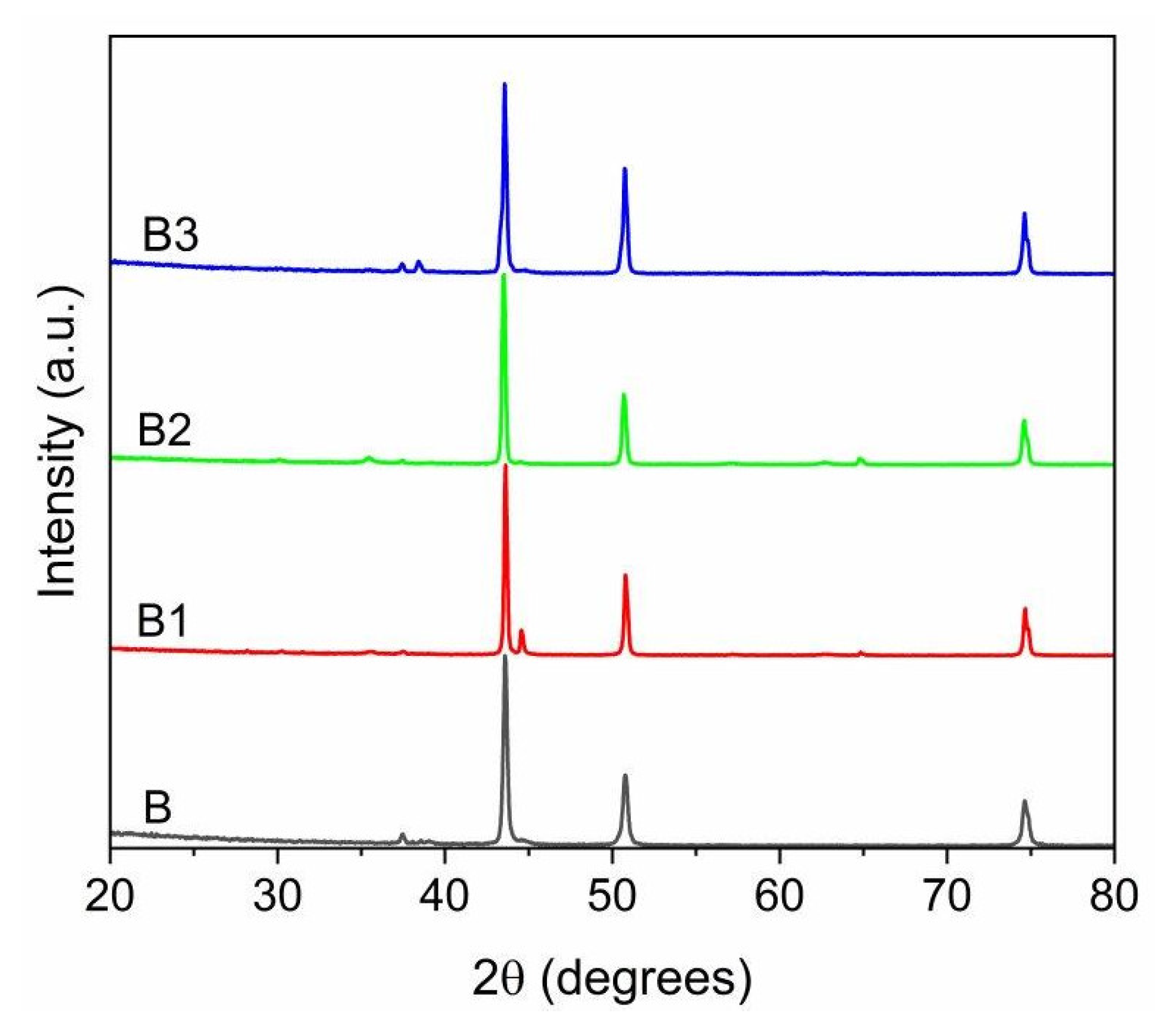
The XRD patterns of the B samples, before and after the plasma treatment, are depicted in
Figure 9.
The B powders, after plasma treatment, exhibit an XRD spectrum which is almost identical to the starting powder. The main phase of the raw powder is austenite, with the corresponding peaks at 2θ values of 43.6°, 50.8°, 74.8°, which turns out to be the most abundant phase in the products. The ferritic phase is nearly absent, and it is only found in notable quantities in the spectrum of the powder treated at 12.5 kW (test B1), the lowest power used in this set of tests. Similarly, as in the case of powder A, it is worth mentioning the formation of oxides: the diffraction peaks related to oxide signals grow at higher power and consequently with the production of nanoparticulate material, more susceptible to oxidation.
The particle size distribution of the powders before and after the plasma treatment are reported in
Table 5. Furthermore, the same table shows the differences between the particles collected at the walls and the bottom of the reactor, which is remarkable. It is worth noting that, in the case of plasma treated A-type powders, most of the particles were collected on the reactor walls after the treatment, with a negligible contribution from the bottom collector. Indeed, in the case of plasma treated B-type powders, the particles exiting the reactor are distributed between the walls and the collector. Generally, the deposition of in-flight-melted and then re-solidified powders takes place mostly on the walls, due to them being cold surfaces, while larger particles settle in the bottom tank. In any case, even in the case of B-type samples, at a higher plasma power, the span decreases and the particle size distribution becomes narrower.
The SEM pictures were used and further processed to measure the particles’ dimensions and, particularly, the degree of spheroidization. Image processing and calculation were carried out with the image editor ImageJ. The circularity (Circ) calculated according to Equation (2) was assumed to be the main reference parameter for the shape factor:
where P and A are particle perimeter and particle area, respectively. The value of circularity varies from 0 to 1, with a perfectly spherical particle having a circularity equal to 1. The tests show that the mean circularity value of the produced particles is always higher than 0.8 (see
Table 6), indicating an extensive spheroidization of the powders whatever the raw powder processed (where as spheroidization is meant the percentage of particles whose circularity is over 0.8). According to the literature [
24,
25], it is recommended that the circularity factor required for powders to be considered for further reuse in AM would be as close to 1 as possible, or at least ≥0.7. Indeed, it is worth noting that, for example, for the A3 test, a spheroidization degree of 85% means that more than 85% of the particles can be used for AM application. Itagaki et al. [
17] also obtained powders with high sphericity and uniform size distribution by performing a DC arc plasma spheroidization under appropriate processing conditions, but nanoparticle-modified spherical particles were already obtained at 17 kW when starting with a raw powder with an averaged diameter of 38 µm. In our work, the spheroidization process was conducted on powders of wider averaged diameter (till to 149 µm) with encouraging results both in terms of sphericity and nanoparticles formation; furthermore, these results are particularly representative due to the relevant dimensions of our experimental set-up, which could be easily scaled up.
An improvement in powder sphericity has the effect of enhancing the flowability and the corresponding apparent density (see
Table 7). Such parameters were calculated for the samples which were washed and purified by dispersing the powders in ethanol and by treating them in an ultrasonic bath.
The A-type powder showed a cohesive behavior during the test, obstructing the exit holes of both Hall and Carney funnels, and therefore not providing any flowability values. The same powder after plasma treatment shows a good flowability. With respect to the B-type powder, we registered an improvement in flowability, passing from a value of about 38.5 s/50 g to 20.5 s/50 g. The goodness of these values is even more remarkable if they are compared with the flowability values obtained for a commercial powder (MARS 316L) in the same experimental conditions (see
Table 8)
To explore the effects of the flow rate and select a production window for our system, several tests have been conducted to find the best process parameters. Due to the large commercial application of the powders in the dimensional range of 15–45 microns, the A-type powder was considered for additional tests. In particular, the A3 powder’s parameters showed the best compromise in terms of spheroidization, distribution, and the production of nanoparticles. On the basis of the results collected, we performed a series of tests at different flow rate values, setting the process power at 15 kW with respect to sample A3 (see
Table 9).
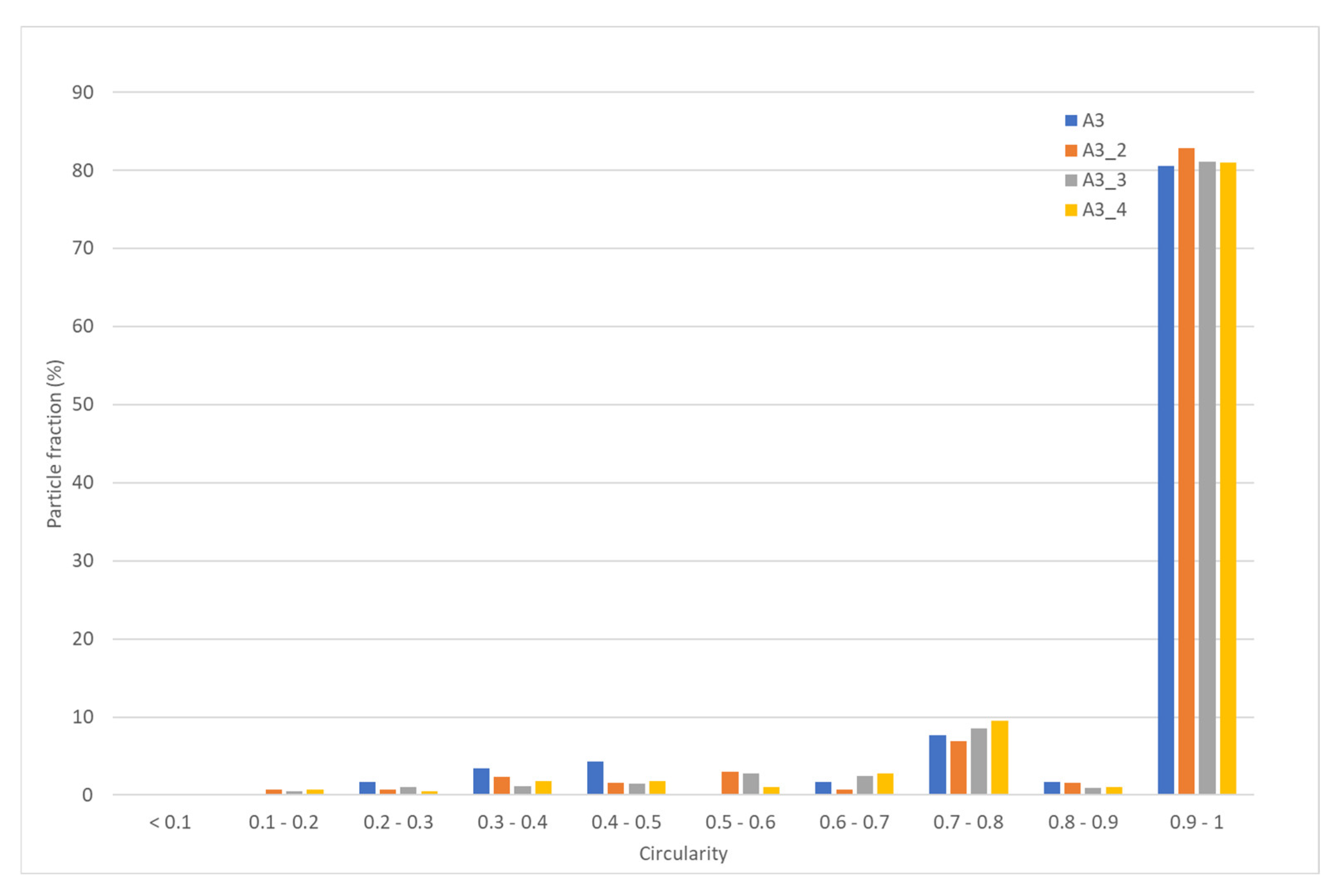
The resulting powders were investigated in terms of their circularity, flowability, and density. With respect to circularity, the data reported in
Figure 10 show that, for the A samples processed at 15 kW, at higher flow rates, the fraction of particles with a circularity higher than 0.9 is more than 80%.
With respect to the particle size distribution, there are no remarkable changes resulting from varying the flow rate (see
Table 10), and in any case, even at the highest tested value, the distribution is similar to that of the commercial powder (see
Table 8), together with the flowability and the density (
Table 11). These results confirm that, in the range of explored flow rates (3–46 g/min), it is possible to raise the productivity of the process without affecting the quality of the product. More tests are indeed necessary to thoroughly explore the system’s limitations and extend the possible applications.

 ,
, 


