Review

A Tutorial on the One-Dimensional Theory of Electron-Beam Space-Charge Effect and Steady-State Virtual Cathode

by
Weihua Jiang
Extreme Energy-Density Research Institute, Nagaoka University of Technology, Nagaoka, Niigata 940-2188, Japan
Plasma 2024, 7(1), 29-48; https://doi.org/10.3390/plasma7010003
Submission received: 27 November 2023 / Revised: 20 December 2023 / Accepted: 2 January 2024 / Published: 5 January 2024
(This article belongs to the Special Issue Latest Review Papers in Plasma Science 2023)

Abstract

:
The space-charge effects of pulsed high-current electron beams are very important to high-power particle beam accelerators and high-power microwave devices. The related physical phenomena have been studied for decades, and a large number of informative publications can be found in numerous scientific journals over many years. This review article is aimed at systematically summarizing most of the previous findings in a logical manner. Using a normalized one-dimensional mathematical model, analytical solutions have been obtained for the space-charge-limited current of both planar diode and drifting space. In addition, in the case of a beam current higher than the space-charge-limited current, the virtual cathode behavior and beam current reflection are quantitively studied. Furthermore, the criteria of steady-state virtual cathode formation are investigated, which leads to the physical understanding of the unstable nature of the virtual cathode. This review article is expected to serve as an integrated source of related information for young researchers and students working on high-power microwaves and pulsed particle beams.

1. Introduction

The space-charge effect of charged particle beams is an important phenomenon for many engineering efforts, such as high-power electron- or ion-beam acceleration, high-current beam transportation, and high-power microwave generation [1,2,3,4,5,6,7,8]. Of particular interest is the high-power microwave device called a virtual cathode oscillator, where the space-charge effect reaches the point in which a virtual cathode is formed [4,5,6,7,8].
The most fundamental basis of space-charge physics has been understood for more than 100 years [1,9,10]. During this time, building blocks have been added by many researchers to make the theory more solid and broad [11,12,13,14,15,16,17,18,19,20,21,22,23,24,25,26]. Most studies, in fact, were carried out since the 1970s when high-power particle beam diodes and high-power microwave devices were intensively studied [22,23,24,25,26,27,28,29,30,31,32,33]. This subject has been investigated for so long and in so much detail that there nearly exists at least one publication on every physically interesting issue that some of us may still be dealing with today. However, many of these publications are so old that they are not easy to acquire, especially for those who have limited access to the huge platforms of the scientific archive. In addition, different papers may have been written in different contexts, for different purposes, and use different mathematical methods with different sets of symbols to represent the same physical quantities. These factors may bring additional difficulties to an already complicated problem, especially for students and young engineers who have just entered this field.
This review article serves as a tutorial for guiding the readers along the general path that our field has walked through over the last decades, starting from the Child–Langmuir law. The aim is to provide a unified description of a series of physical phenomena using a consistent mathematical language. The idea is to put together many smaller pieces that have been scattered over a long period and in a variety of journals so that a clearer picture can be seen by those who are new to this subject. Therefore, the purpose of this article is not to publish any novel findings, nor is it aimed at experienced researchers who are familiar with every physical detail.
This article only deals with steady-state issues without considering any transient effects. The reason is that the space-charge effect is primarily a matter of space, where time becomes important only when instability develops. Therefore, although time-dependent events frequently occur in real devices, the steady states often serve as a backbone that lies at the center of the fluctuation or oscillation. In addition, the steady-state approach is much easier and straightforward in most cases, with which we can better grasp the physical relations between different quantities and phenomena.
In the next section, we first deal with a one-dimensional acceleration gap in which electrons with zero initial kinetic energy are accelerated, for which the space-charge-limited current is obtained. Then, in Section 3, we consider the situation where an electron beam with the initial electron kinetic energy is injected into a drifting space for cases of beam current below or above the space-charge-limited current. These two situations are put together in Section 4, where electrons accelerated by the acceleration gap are injected into the drifting space. Stability analysis has been carried out from which we have concluded that there exists a parameter range where no stable steady-state solutions can be obtained.

2. Space-Charge Limited Current in an Acceleration Gap

Consider an electron beam being accelerated by a voltage applied between two planar electrodes facing each other in parallel, as shown conceptually in Figure 1. In a steady state, if the cross-sectional size of the electron beam is much larger than the distance between the electrodes, all parameters can be considered as functions of the only spatial variable, which is in the direction of the acceleration. This is the classic model for studying one-dimensional space-charge-limited current, assuming the electrons have zero initial kinetic energy.

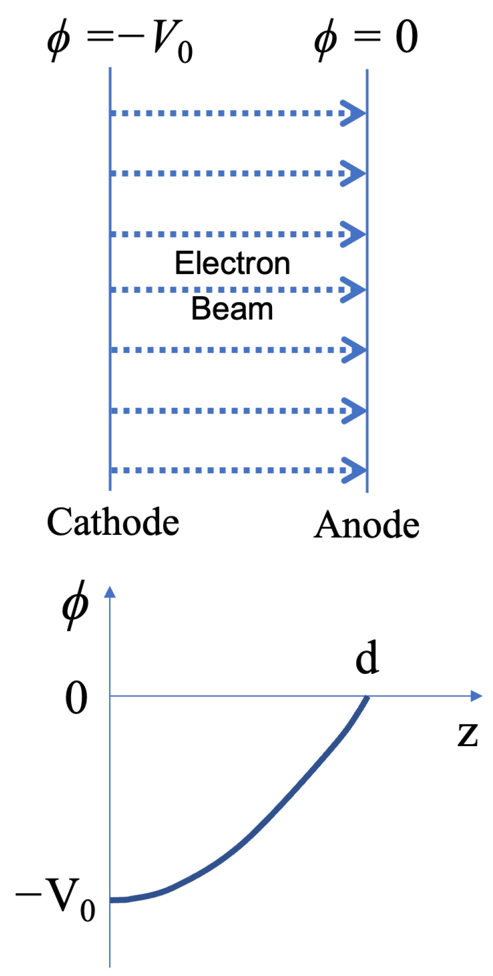
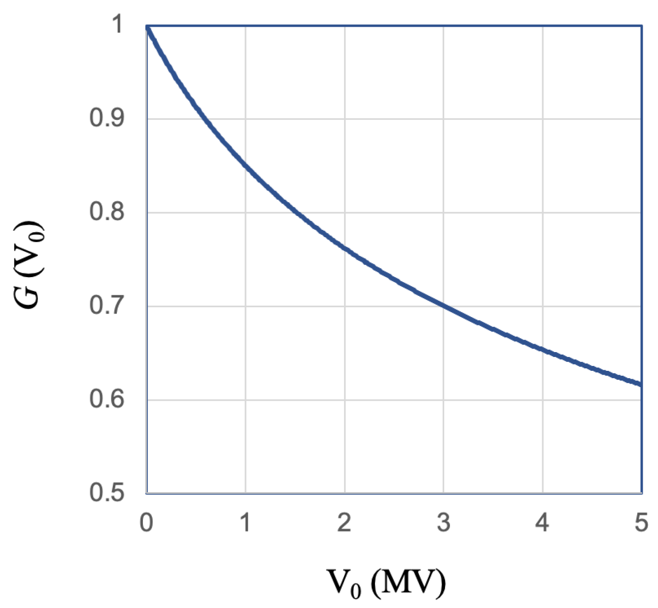
2.1. Non-Relativistic Space Charge Limited Current

In case the relativistic effect is not important, the physical parameters are related to each other via the following equations.
d E d z = e n ε 0
E = d ϕ d z
J = e n v
1 2 m v 2 = e V 0 + ϕ
where E(z), ϕ(z), n(z), and v(z) are functions of coordinate z, and they represent the electric field, the electric potential, the electron density, and the electron velocity, respectively. J is the electron beam current density, which does not change with z in a steady state. In addition, the constants e, m, ε0, and V0 represent the unit charge, electron mass, vacuum permittivity, and the applied acceleration voltage, respectively.
In order to normalize the parameters, we define the following normalization constants.
E 0 = V 0 d
ϕ 0 = V 0
n 0 = ε 0 V 0 e d 2
v 0 = 2 e V 0 m 1 / 2
J 0 = ε 0 2 e m 1 / 2 V 0 3 / 2 d 2
z 0 = d
where d is the distance between the electrodes, namely the acceleration gap width. Using the above constants, we can define the dimensionless quantities E′, ϕ′, n′, v′, J′, and z′ by using
E = E E 0
ϕ = ϕ ϕ 0
n = n n 0
v = v v 0
J = J J 0
z = z z 0
and obtain the following equations by inputting them into Equations (1)–(4).
d E d z = n
E = d ϕ d z
J = n v
v 2 = 1 + ϕ
The relations of Equations (5)–(10) are important for nondimensionalizing the parameters and simplifying the equations. They are used throughout this article.
Since E′, ϕ′, n′, and v′ are all monotonic functions of z′ in case of zero initial velocity, they can be considered as functions of each other. Therefore, by submitting Equations (17)–(20) into each other, we obtain
d E = n d z = n E d ϕ = J E v d ϕ = J E d ϕ 1 + ϕ
from which we can solve E’ as a function of ϕ’ and yield the following relation.
1 2 E 2 = 2 J 1 + ϕ + C
where C is an integration constant, which is determined by the boundary condition. The above relation reveals a very important physical phenomenon of the so-called space-charge effect. Since the negatively charged electrons are accelerated in the positive z direction, the beam current density J′ is always negative. Therefore, the electric field intensity |E′| always increases as the potential varies from the cathode to the anode, i.e., when ϕ′ increases from −1 to 0. In other words, the weakest electric field is observed on the surface of the cathode, where the electrons have zero kinetic energy.
From Equation (22), we can see that the space-charge effect described above depends on the value of J′. The higher |J′| is, the lower the field strength on the cathode surface becomes because the integration of the electric field over the gap, which is the gap voltage, is constant. Therefore, we can perceive that the maximum value of |J′| is reached when the cathode electric field diminishes to zero or
E ϕ = 1 = 0             C = 0
The maximum value of |J′|, denoted as |JSCL|, is called the space-charge-limited current. From Equations (22) and (23), we obtain
E ( ϕ ) = 4 J S C L 1 + ϕ 1 / 2
This is a well-defined relation between E′ and ϕ′, which does not depend on z′ in appearance. However, to find out JSCL, we have to calculate the spatial integration as follows:
0 1 d z = 1 0 d ϕ E = 1 4 J S C L 1 2 1 0 d ϕ 1 + ϕ 1 / 4 = 4 3 1 4 J S C L 1 2
Using the fact that the above integration equals unity, we obtain
J S C L = 4 9
With Equations (9) and (15), we arrive at the well-known expression for the one-dimensional, non-relativistic space-charge-limited (SCL) current density
J S C L = 4 ε 0 9 2 e m 1 / 2 V 0 3 / 2 d 2
which is also called the Child–Langmuir law. When the beam current reaches this value, the electron space charge completely shields the cathode surface from the electric field, and we consider the gap to be in a space-charge-limited state. In this state, we can use Equation (24) to calculate the electric field on the anode surface (ϕ′ = 0).
E ϕ = 0 = 4 J S C L 1 2 = 4 3
Therefore, although the space-charge effect reduced the cathode surface (ϕ′ = −1) field to zero, it enhanced the anode surface field by a factor of 4/3, compared with the average value (E0).
By using Gauss’ law, we can calculate the total charge (per unit area) between two electrodes.
Q = ε 0   E ϕ = 0 E 0 = 4 ε 0 3   V 0 d
Furthermore, by dividing this charge with the current, we can obtain the transit time of the electrons, which is the time of flight from cathode to anode.
t T O F = Q J S C L = 3 d m 2 e V 0 1 2 = 3 d v 0
where v0 is defined by Equation (8). It is the electron velocity when it arrives at the anode.

2.2. Relativistic Space Charge Limited Current

In case the relativistic effect has to be taken into account, Equation (4) is replaced by
v = c 1 γ 2 1 / 2 ,                 w h e r e       γ = 1 + e ( V 0 + ϕ ) m c 2
while Equations (1)–(3) remain unchanged. By defining a new dimensionless constant
x 0 = e V 0 m c 2
we can derive
γ = 1 + x 0 1 + ϕ
v = v m 2 e V 0 = 1 2 x 0 1 1 + x 0 1 + ϕ 2 1 / 2
As in Equation (21), we can derive
d E = J E v d ϕ = J E 2 x 0 1 1 + x 0 1 + ϕ 2 1 / 2 d ϕ
and obtain
1 2 E 2 = J 2 x 0 1 + x 0 1 + ϕ 2 1 + C
This is the relativistic form of Equation (22). However, regarding the space-charge effect, Equations (36) and (22) are similar in understanding the fact that the electric field intensity |E′| keeps increasing when ϕ′ increases from −1 to 0. As in the non-relativistic case, the maximum current density, here denoted as |JRSCL|, corresponds to the condition of E′(ϕ′ = −1) = 0, with which the following relation is obtained.
E ϕ = 2 J R S C L 2 / x 0 1 + x 0 1 + ϕ 2 1 1 2
To find out JRSCL, we have to calculate the spatial integration which, unfortunately, is not as easy as in the non-relativistic case.
0 1 d z = 1 2 J R S C L x 0 / 2 1 2 1 0 1 + x 0 1 + ϕ 2 1 1 / 4   d ϕ
By defining x = x 0 1 + ϕ , we can rewrite the above equation as
1 2 J R S C L x 0 / 2 1 2 1 x 0 0 x 0 x + 1 2 1 1 4   d x = 1
using which we can express JRSCL as
J R S C L = 1 2 2 1 x 0 3 / 2 0 x 0 x + 1 2 1 1 4   d x 2 J S C L G x 0
The above equation tells us that the relativistic space-charge-limited (RSCL) current density can be expressed as a product of the nonrelativistic space-charge-limited current density (JSCL) and function G(x0), which is defined as
G x 0 = 9 8 2   1 x 0 3 / 2 0 x 0 x + 1 2 1 1 4   d x 2
Although it is not easy to calculate the value of G(x0) analytically, the above integration can be solved numerically without much difficulty. Figure 2 shows the computation results, with x0 replaced by V0 using Equation (32). The curve of Figure 2 tells us how much we should care about the relativistic effect on the space-charge-limited current. For example, when the acceleration voltage is lower than 500 kV, the difference between JSCL and JRSCL is less than 10%. In any case, we can obtain the exact relativistic value by applying Equation (27) with the value of G, as shown in Figure 2 for V0 < 5 MV.

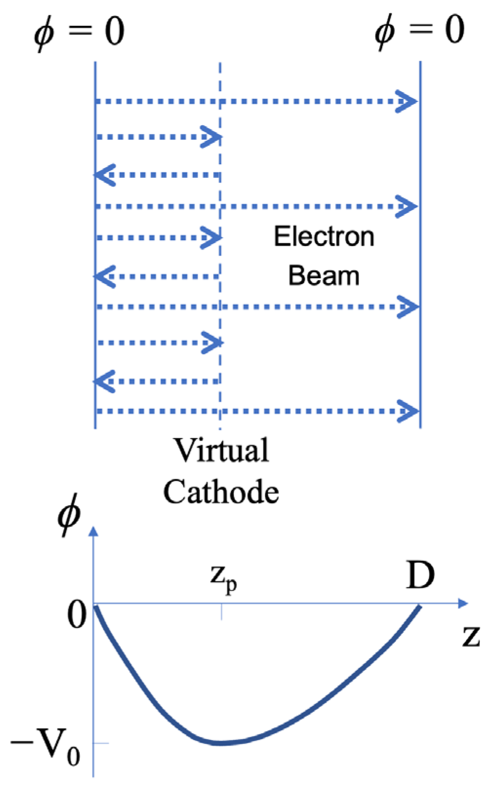
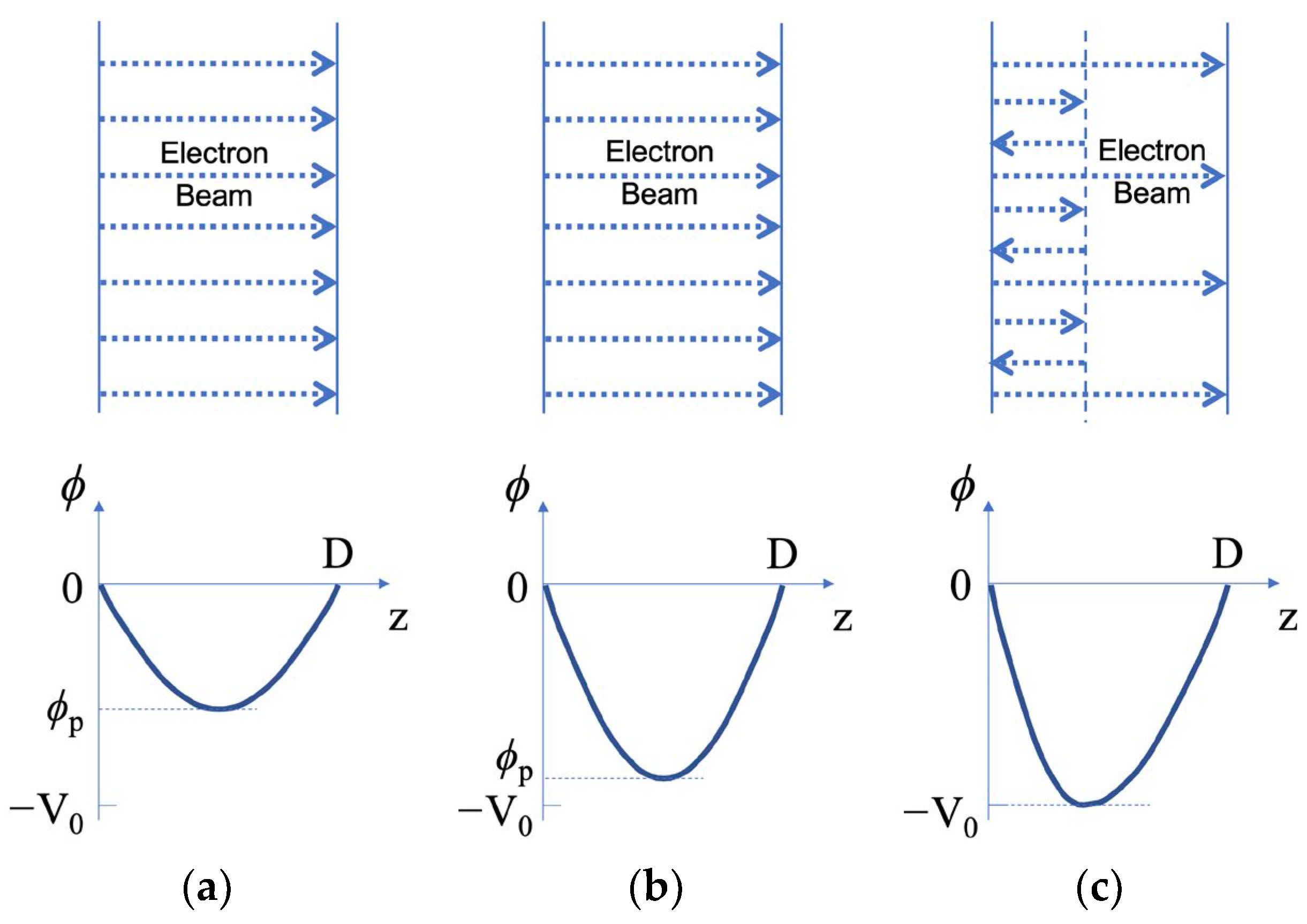
3. Electron Beam Injection into a Drifting Space

In the last section, we have considered the situation where an electron beam with zero initial electron kinetic energy is accelerated by a gap with constant voltage. Next, we consider a different case where an electron beam with a certain initial electron kinetic energy is injected into a drifting space with zero voltage applied between two boundaries, as shown in Figure 3.

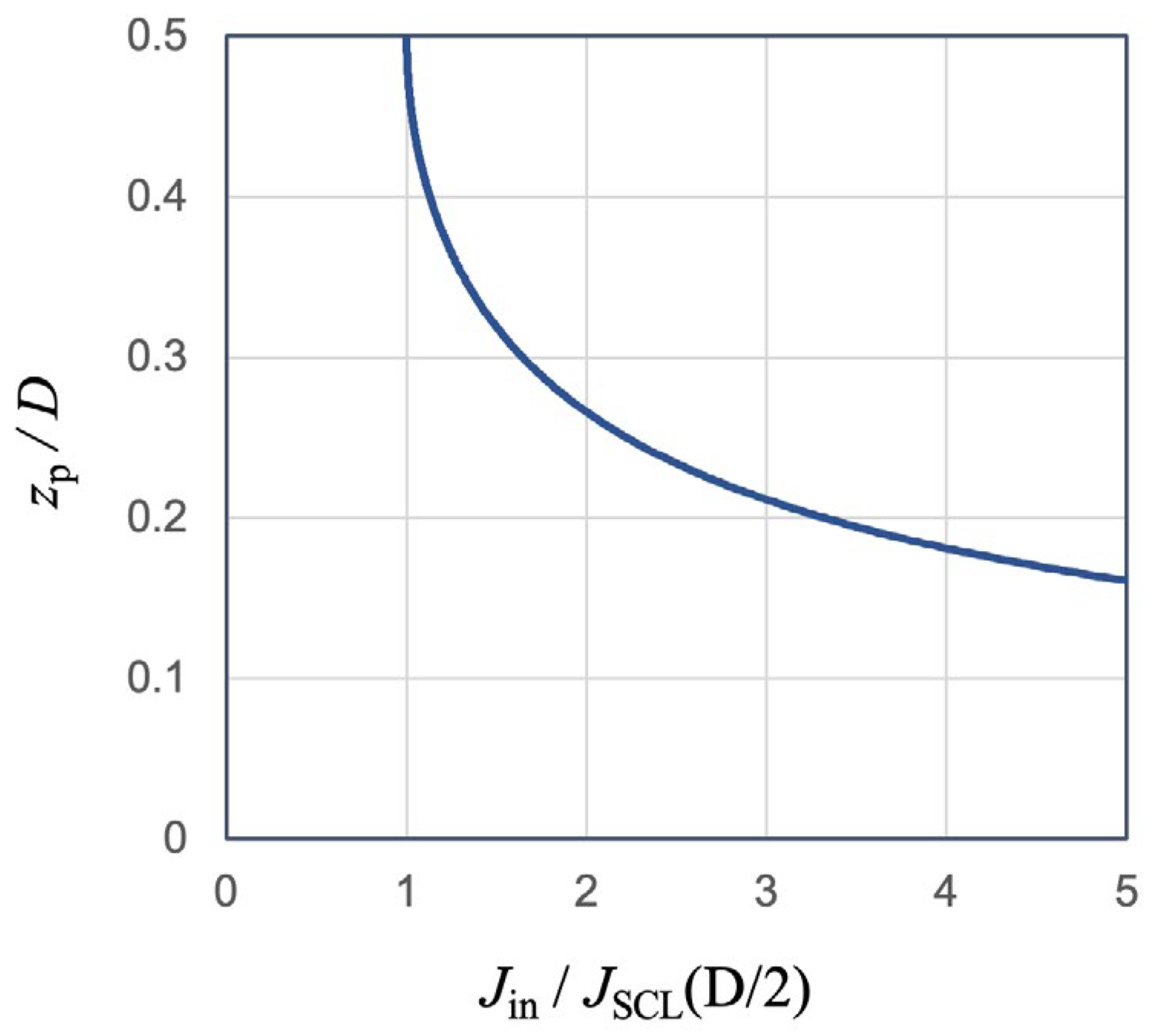
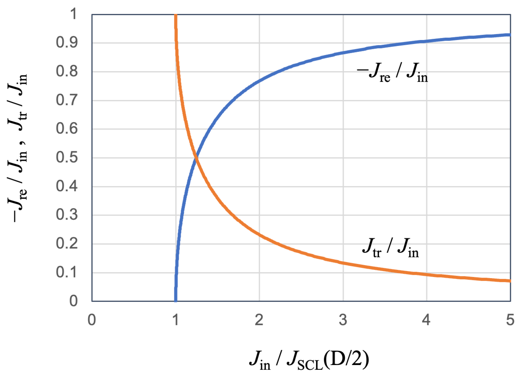
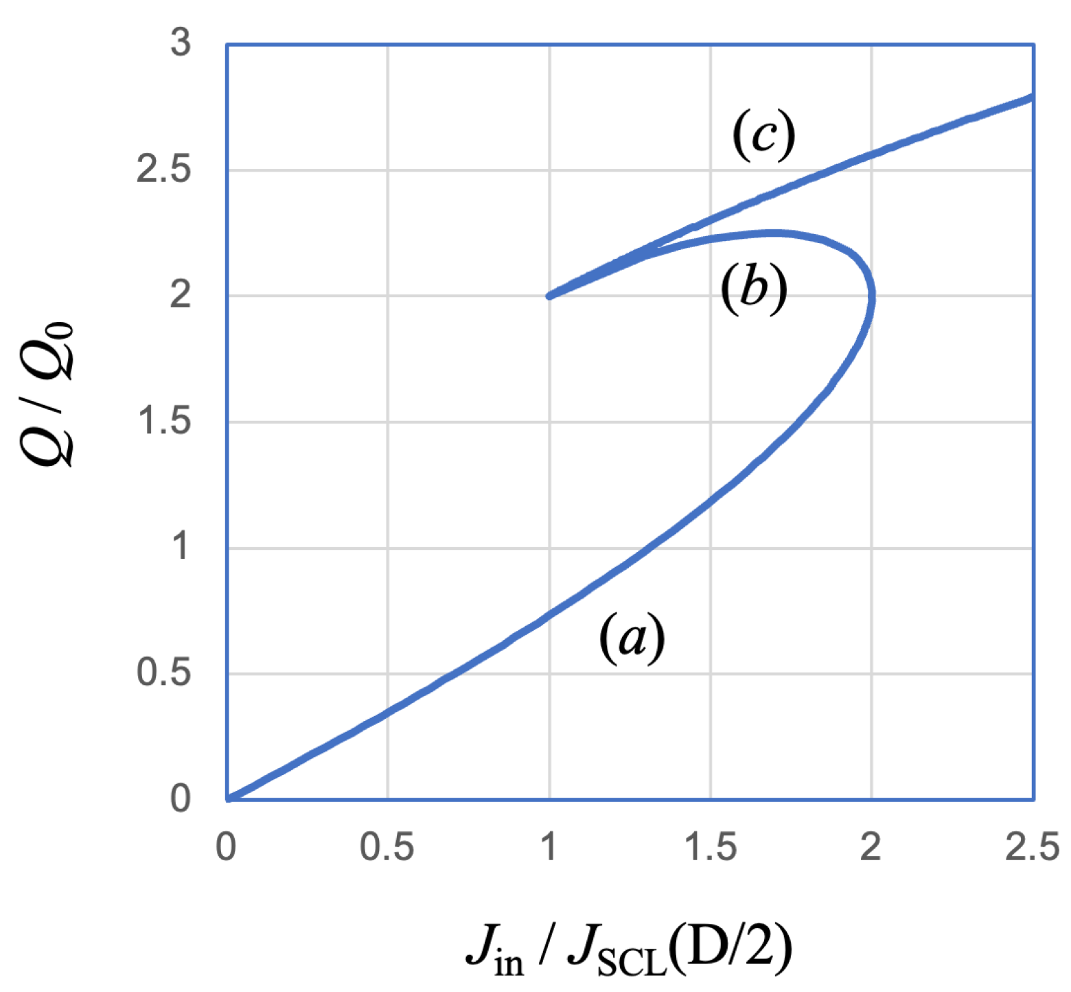
3.1. When Beam Current Density Is Relatively Low

When the beam current density is relatively low, we can assume that all electrons can go through the gap and arrive at the opposite electrode, which is different from the situation described in the next subsection (Section 3.2).
We assume that the initial electron kinetic energy is eV0, the injected beam current density is Jin, and the gap length of the drifting space is D. The basic equations are the same as Equations (17)–(20). To continue using the normalization relations of Equations (11)–(16), we define the spatial normalization constant
d = 4 ε 0 9 2 e m 1 / 2 V 0 3 / 2 J i n
with which the drifting space gap is normalized as
D = D d
and the normalized injected beam current density becomes
J i n = J i n J 0 = 4 9
where J0 is the same as defined by Equation (9). The physical meaning of d will be seen more clearly in Section 4.
Since the electron beam passes through the gap entirely, in steady state, the electric potential must have a symmetric distribution relative to its center at z = D/2. The potential minimum (ϕp) appears at the center where the electric field is zero, namely
E ϕ p = 0                     ϕ p = ϕ p V 0
Substituting Equation (45) into Equation (22), we obtain
C = 2 J i n 1 + ϕ p = 8 9 1 + ϕ p
and then
E ϕ = ± 4 3 1 + ϕ 1 + ϕ p 1 2
If we only look at the left half of the gap, where 0 < z < D/2, we have positive E′ in the above equation.
As in the last section, the integration of 1/E′(ϕ′) gives spatial information such that
D 2 = 0 ϕ p d ϕ E ( ϕ ) = 3 4 0 ϕ p d ϕ 1 + ϕ 1 + ϕ p 1 2 = 1 1 + ϕ p 1 / 2 1 + 2 1 + ϕ p
Using the above relation, we can express the following current ratio as a function of ϕp.
J i n J S C L ( D / 2 ) = J i n J S C L ( D / 2 ) = D 2 2 = 1 1 + ϕ p 1 + 2 1 + ϕ p 2 f ϕ p
where JSCL(D/2) is the space-charge-limited current density defined by
J S C L D / 2 = 4 ε 0 9 2 e m 1 2 V 0 3 / 2 D / 2 2               o r           J S C L D / 2 = 4 9 D 2 2
It is, according to the previous section, the maximum current density that can be obtained by acceleration voltage V0 with a gap of D/2. It is important that, for a given V0 and D, JSCL(D/2) is constant. Therefore, Equation (49) actually shows the relation between the injected current density and the value of the minimum potential. This relation is plotted in Figure 4 with ϕp on the vertical axis and Jin/JSCL(D/2) on the horizontal, although the following four points can be easily identified by using Equation (49).
f 0 = 0 ,       f 1 / 4 = 1 ,       f 3 / 4 = 2 ,       f 1 = 1
When the amplitude of the injected current density (|Jin|) is increased, the minimum potential decreases monotonically until |Jin| reaches its maximum value at
J m a x = 2 J S C L D / 2
Since there is no solution of ϕp for Jin/Jmax > 1, this maximum value |Jmax| is, therefore, the maximum current density that can be carried by the electron beam through the gap. It is referred to as the space-charge-limited current of an electron beam in a drifting space, for initial electron energy of V0 and gap width of D. Therefore, only when the condition
J i n J S C L ( D / 2 ) 2
is satisfied, the electron beam can drift across the gap in its entirety.
From Figure 4, one can see that, for the region of −0.75 < ϕp < 0, we have Jin/JSCL(D/2) < 2. For ϕp = −0.75, we have Jin/JSCL(D/2) = 2. Furthermore, for the region of −1 < ϕp < −0.75, we have 1 < Jin/JSCL(D/2) < 2. In other words, the maximum beam current appears when the minimum potential reaches −0.75V0. If the potential dips more than this value, the corresponding current amplitude actually becomes smaller. As a result, in the region of 1 < Jin/JSCL(D/2) < 2, two solutions of ϕp exist for any given value of Jin. This can be generally explained by the fact that a small number of electrons moving at a relatively high speed can carry the same current as that of a large number of electrons moving at a relatively low speed. Therefore, too many electrons may create a space-charge effect that leads to significantly reduced electron velocity. The highest flux is reached only when a modest number of particles are traveling at a reasonable speed.
To calculate the electric field at the boundaries (ϕ′ = 0), we use Equation (47),
E ϕ = 0 = ± 4 3 1 1 + ϕ p 1 2
from which we can further calculate the total charge (per unit area) between two boundaries.
Q = 2 ε 0   E ϕ = 0 = 8 ε 0 3   V 0 d 1 1 + ϕ p 1 2 = 8 ε 0 3 V 0 D / 2 D 2 1 1 + ϕ p 1 2
Combined with Equation (48), we obtain
Q Q 0 = 2 1 1 + ϕ p 1 + 2 1 + ϕ p
where Q0 is defined as
Q 0 = 4 ε 0 3 V 0 D / 2
By comparing Equation (56) with Equation (29), we can tell that Q0 corresponds to the charge in a space-charge-limited gap having a width of D/2. So, if we define
t 0 = 3 D / 2 v 0
following Equation (30), we can obtain the transit time (time of flight) of electrons through the drifting space by dividing the total charge with the current density and using Equations (55), (30) and (49).
t T O F = Q J i n = Q Q 0 Q 0 J S C L D / 2 J S C L D / 2 J i n = 2 t 0 1 + 2 1 + ϕ p
Using this relation, we can calculate the following results as examples:
t T O F ϕ p = 0 = 2 t 0 3 = D v 0
t T O F ϕ p = 3 4 = t 0
t T O F ϕ p = 1 = 2 t 0
They correspond to the cases of constant velocity (zero beam current), maximum beam current, and lowest minimum potential, respectively.

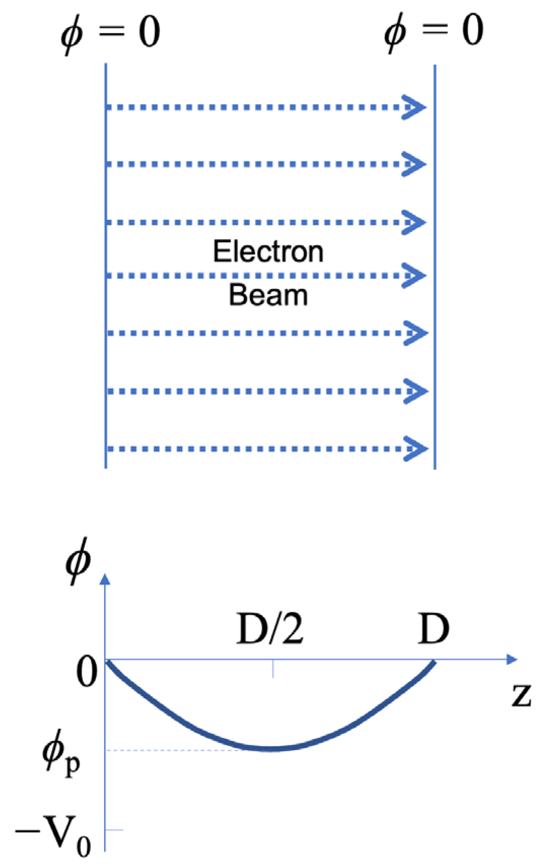
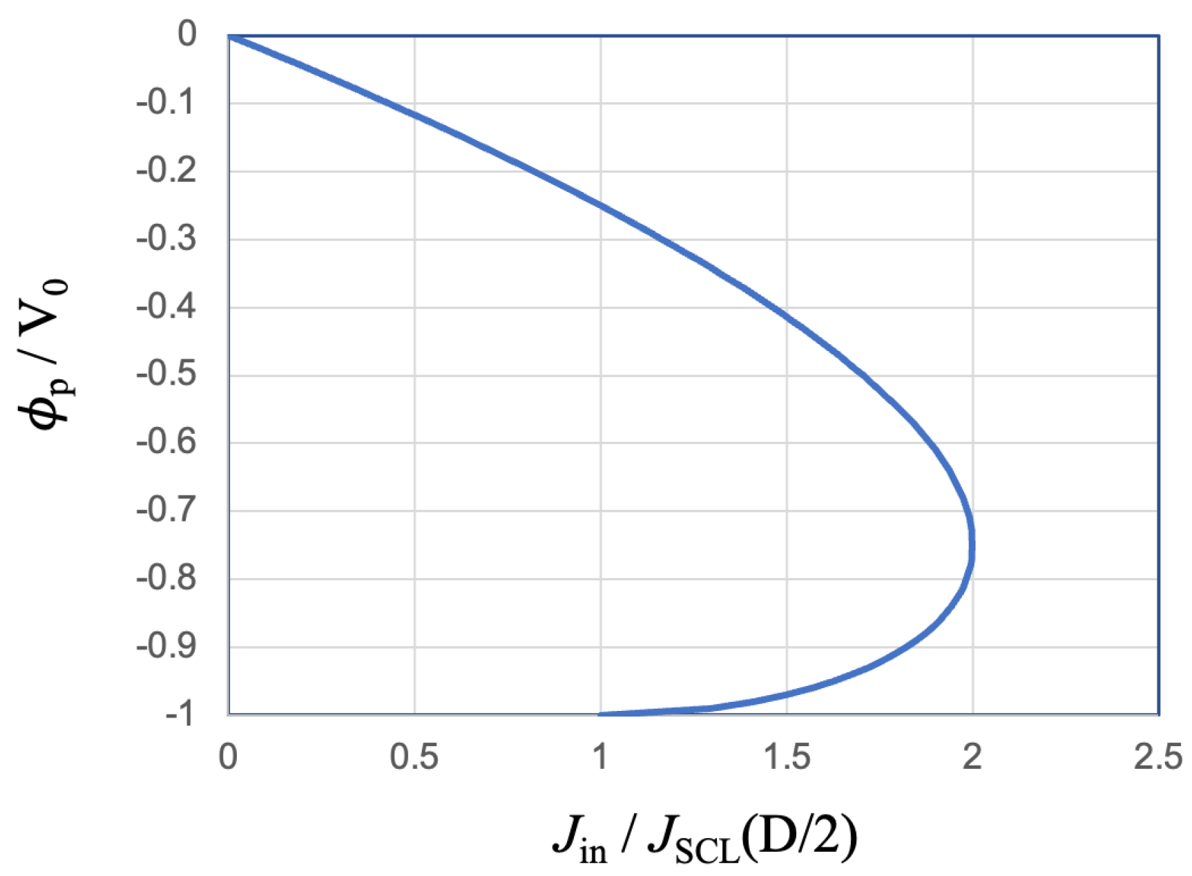
3.2. When Beam Current Density Is Higher Than the Limiting Value

When the amplitude of the injected beam current density (|Jin|) is higher than the limiting value, which is defined by Equation (51), one thing we know for sure is that not all electrons can pass through the gap to the other side because such steady-state solution does not exist. In this case, the only physically feasible situation is that some of the electrons turn around at a certain point and move back toward the injection plane while the others continue moving forward. In other words, the space charge of the electron beam partially reflects the electron beam at a certain position somewhere in the gap, as depicted in Figure 5. The position of electron beam reflection is denoted as zp.
In a steady state, at the location of zp, the electron kinetic energy drops to zero, and, according to the law of energy conservation, the electric potential must be −V0. Assuming the injected electron beam has been accelerated by a gap like that shown in Figure 1 where the cathode has a potential of −V0, since the potential at zp has the same value as that of the cathode, this position is called a virtual cathode.
On the right-hand side of zp, the transmitted electron beam passes through with a current density of Jtr. In the space between the injection plane and zp, however, there are two electron beams: the incoming beam with the current density of Jin and the reflected beam with the current density of Jre. Since electrons are carrying negative charges, we should have Jin < 0, Jtr < 0, and Jre > 0. In addition, they have the following relation with each other:
J i n = J r e J t r
after normalization by J0.
It is important to note that, although the injected beam and the reflected beam cancel each other partially in current, they enhance each other in the space-charge effect because it does not matter which direction the electrons are moving when we take their space charge into account. Therefore, in terms of space charge, the beam current amplitude is −Jin + Jre on the left-hand side of zp and −Jtr on the right-hand side. Since we have
E z p = 0 and ϕ z p = V 0
the beam current amplitude on both sides of zp should satisfy the space-charge-limited conditions described in Section 2.1. Thus, we have
J i n + J r e = 4 9 1 z p 2
J t r = 4 9 1 D z p 2
where zp = zp/d and d are defined in Equation (42). From the above relations, we can further obtain
2 J i n = J i n + J r e J t r = 4 9 1 z p 2 + 1 D z p 2
and by using Equation (50), we find
J i n J S C L ( D / 2 ) = 1 8 1 ( z p / D ) 2 + 1 ( 1 z p / D ) 2
Since all quantities are expressed in ratios of the same physical parameter, we can remove the apostrophe (‘), which is used to indicate a parameter after normalization. In other words, the equation for the parameters before normalization should have the same form as Equation (64), namely,
J i n J S C L ( D / 2 ) = 1 8 1 ( z p / D ) 2 + 1 ( 1 z p / D ) 2
The above equation gives the relation between the injected beam current density (Jin) and the position of the virtual cathode (zp). This relation is plotted in Figure 6 from which we can see that, as Jin increases, the virtual cathode moves closer to the injection position and that, as Jin decreases toward JSCL(D/2), zp approaches D/2.
Using Equations (61), (62) and (64), we can obtain the following relations, after removing the apostrophes.
J r e J i n = 1 z p / D 2 z p / D 2 1 z p / D 2 + z p / D 2
J t r J i n = 2 ( z p / D ) 2 ( 1 z p / D ) 2 + ( z p / D ) 2
With Equation (65), the above relations are plotted in Figure 7. As shown in Figure 7, when Jin = JSCL(D/2), we have Jre = 0 and Jtr = Jin, indicating 100% beam transmission. As |Jin| increases, however, we see a drastic increase in Jre and a decrease in |Jtr|. For example, when Jin = 2JSCL(D/2), we have approximately −Jre/Jtr ≈ 3:1, indicating a situation that most of the electron beam is reflected.
Although the title of this subsection suggests that we are only investigating the situation for Jin > 2JSCL(D/2), we did find the steady-state solutions for the region of 1 < Jin/JSCL(D/2) < 2 under the assumption that a virtual cathode is formed. Therefore, together with what we have obtained in the last subsection, there are totally three possible states for each value of Jin in the region of 1 < Jin/JSCL(D/2) < 2. They are marked by (a), (b), and (c), respectively, in Figure 8, which is a replot of Figure 4 by adding the fact that the potential of the virtual cathode is always −V0 for steady states. These three states (a, b, and c) will be considered in more detail in the next subsection.
As we have shown in the last subsection, we can use the electric field to calculate the total charge (per unit area) in the gap based on Gauss’ law. Since the current amplitudes on both sides of zp satisfy the space-charge-limited conditions, using Equations (24), (61) and (62), we can write
Q = 4 3 V 0 d 1 z p + 1 D z p = 4 3 V 0 D / 2 D 2 1 z p + 1 D z p = Q 0 2 1 z p / D + 1 1 z p / D
where Q0 is defined by Equation (56). As to the transit times, the satisfaction of space-charge-limited condition in both regions allows us to use Equation (30) for the transmitted and reflected electrons, respectively,
t T O F t r a n s m i t t e d = 3 D v 0
t T O F r e f l e c t e d = 6 z p v 0
It is seen from Equation (69) that the transit time of the transmitted electrons does not depend on where the virtual cathode is.

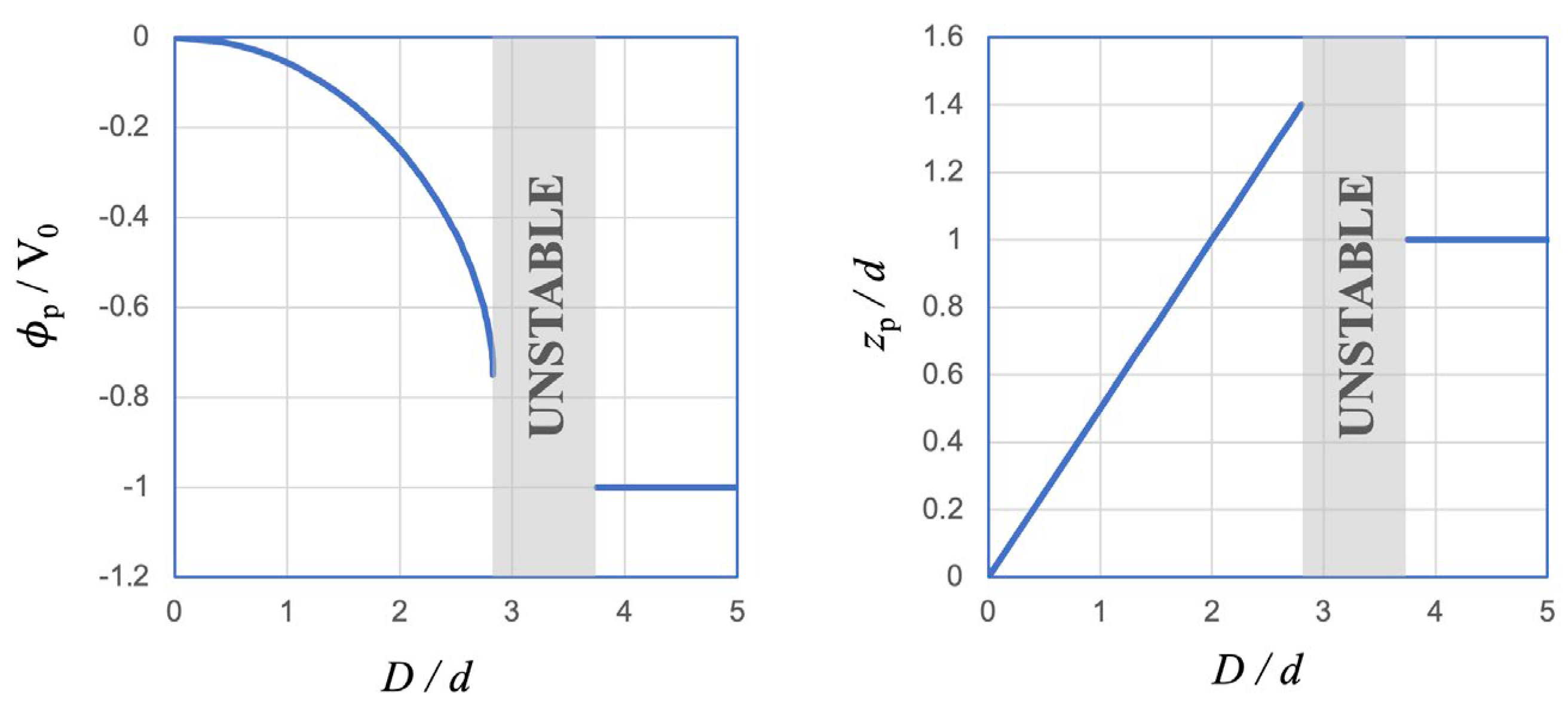
3.3. Stable State and Unstable State

To compare the different states marked by (a), (b), and (c) in Figure 8, we consider the situation that the amplitude of the injected beam current density (|Jin|) increases slowly from zero. Here, “slowly” means that a steady state is always maintained in the process. Then, as |Jin| is increased, the value of the minimum potential in the gap (ϕp) decreases continuously until it reaches −0.75V0 at Jin = 2JSCL(D/2), along the pass marked by (a) in Figure 8. Up to this point, no virtual cathode appeared in the gap, and the electron beam was 100% transmitted. From here, however, if the injected beam current is further increased, there exists only one solution, as can be seen in Figure 8 for Jin/JSCL(D/2) > 2, which is marked by (d). This is the state we have described in Section 3.2.
The above description implies a significant phenomenon, which leads to the following parameter jumps (discontinuous variations) when the injected beam current crosses the line of Jin = 2JSCL(D/2), represented by the thick line in Figure 8:
  • Minimum potential (ϕp/V0): −0.75 → −1 (Figure 8);
  • Position of minimum potential (zp/D): 0.5 → ~ 0.26 (Figure 6);
  • Reflected beam current ratio (Jre/Jin): 0 → ~ 0.77 (Figure 7);
  • Transmitted beam current ratio (Jtr/Jin): 1 → ~ 0.23 (Figure 7).
Therefore, when the injected beam current exceeds the space-charge-limited current of the drifting space, the virtual cathode formation is accompanied by sudden changes in the major parameters, at least from the steady-state point of view.
As for the states marked by (b) and (c) in Figure 8, they are just different mathematical solutions that satisfy the model described in Section 3.1 and Section 3.2. These states are never reached in the process of the current rise, as seen above. In addition, these states are physically different from those marked by (a) as explained below.
The three states, represented by (a), (b), and (c) in Figure 8, are schematically illustrated in Figure 9.
In state (a), the electron beam is 100% transmitted. The potential is higher than that of state (b), indicating a relatively high electron velocity and low electron number density. In this state, a slight increase in the beam current leads to a lower minimum potential (higher in the absolute value of its amplitude). The enhancement of the space-charge effect tends to suppress the beam current and hence stabilize the system. Therefore, state (a) is a stable state.
In state (b), the electron beam is also 100% transmitted. However, compared with state (a) for the same value of Jin, the potential minimum ϕp is lower, which leads to relatively low electron kinetic energy and high electron number density. In this state, a slight increase in the beam current leads to a higher minimum potential (lower in the absolute value of its amplitude). The weakening of the space-charge effect tends to further enhance the beam current and hence destabilize the system. Therefore, stage (b) is an unstable state.
In state (c), a virtual cathode is formed where a fraction of the electron beam is reflected. The ratio of the reflected beam current to the injected beam current can be found mathematically, as described in Section 3.2, by using the condition that the minimum potential equals −V0. However, there is no physical mechanism that enforces this balance between the current ratio and the potential distribution. For example, a slight increase in the minimum potential (decrease in its absolute amplitude) may cause an increase in the electron kinetic energy, which leads to a higher ratio of the transmitted beam current. As a result, the number of electrons, the space charge of which forms the virtual cathode, decreases, leading to a further decrease in the virtual cathode amplitude. Therefore, state (c) is not a stable state either. In fact, from this point of view, no virtual cathode is stable, including those in the region of Jin/JSLC(D/2) > 2. This is the physical explanation for the so-called virtual cathode oscillation [27,28,29,30,31,32,33], which is beyond the scope of this article.
Finally, we compare the total charge (per unit area) in the gap. Equations (55) and (68) are plotted in Figure 10, where ϕp and zp/D have been replaced by Jin/JSCL(D/2) using (49) and (65), respectively. From Figure 10, we can see that state (c) has the highest total electron number, and state (a) has the lowest one. Based on the fact that, in a steady state, all electrons enter or exit the gap with exactly the same kinetic energy, we can tell that state (c) possesses the highest internal energy and state (a) has the lowest value. Since the electrical potential is formed by the electron beam itself, it is natural to imagine that the electrons may rearrange themselves so that they possess less total energy, while it is difficult to anticipate that the opposite behavior might occur. Therefore, even if, for some reason, state (b) or state (c) is temporarily observed, it tends to decay by lowering its potential barrier and releasing some of the stagnated electrons and shift to state (a).
Therefore, the conclusion is that, although we have found three possible states (a), (b), and (c) in the parameter range of 1 < Jin/JSLC(D/2) < 2, only state (a) is stable. Although the discontinuity between state (a) and state (d) mains a problem, which can only be dealt with by using transient theories, they cover the whole axis of Jin. In other words, for any injected beam current density, we can find a steady-state solution for the electron beam, whether it can pass through the gap completely or it is partially reflected by the virtual cathode.

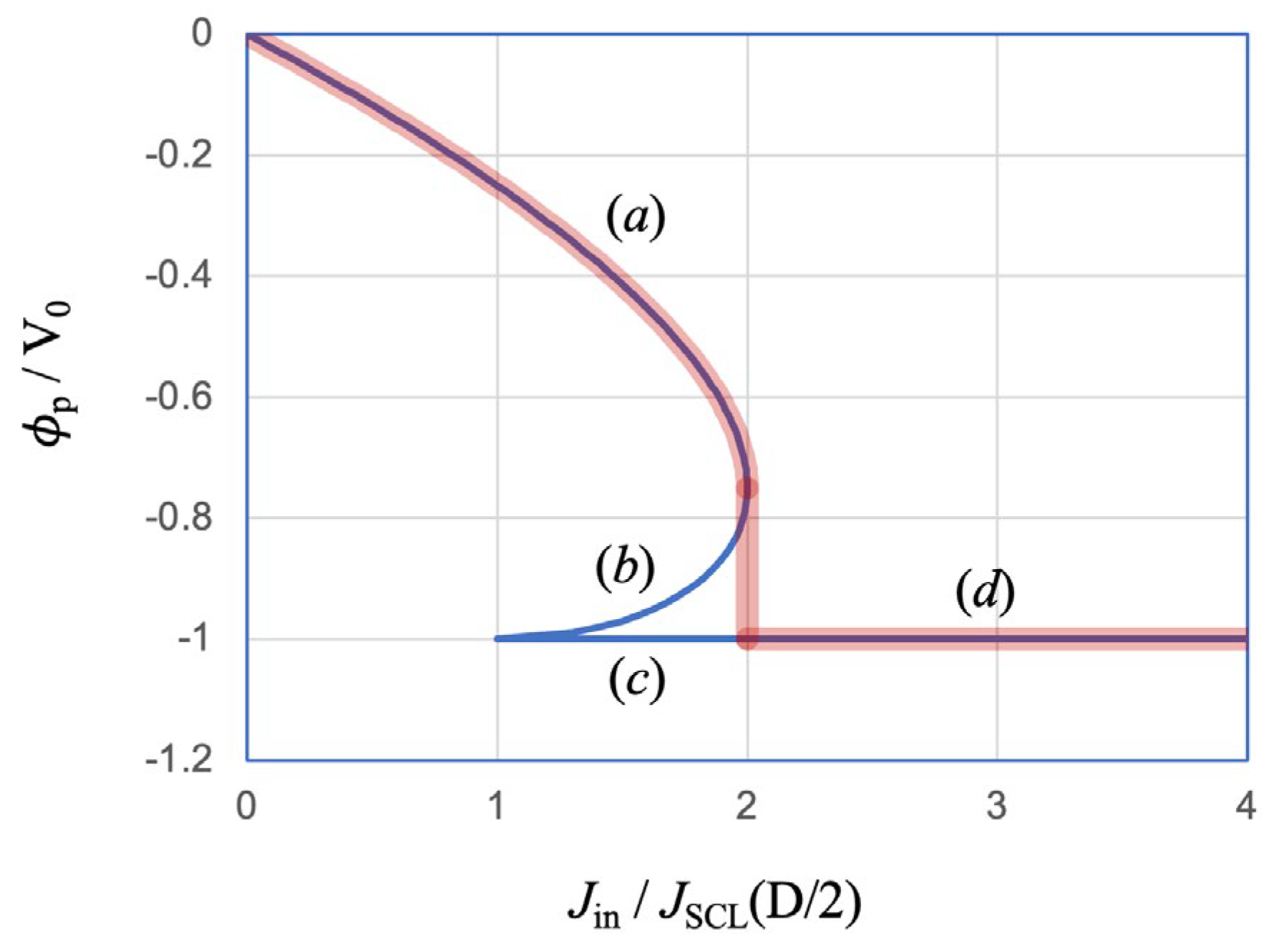
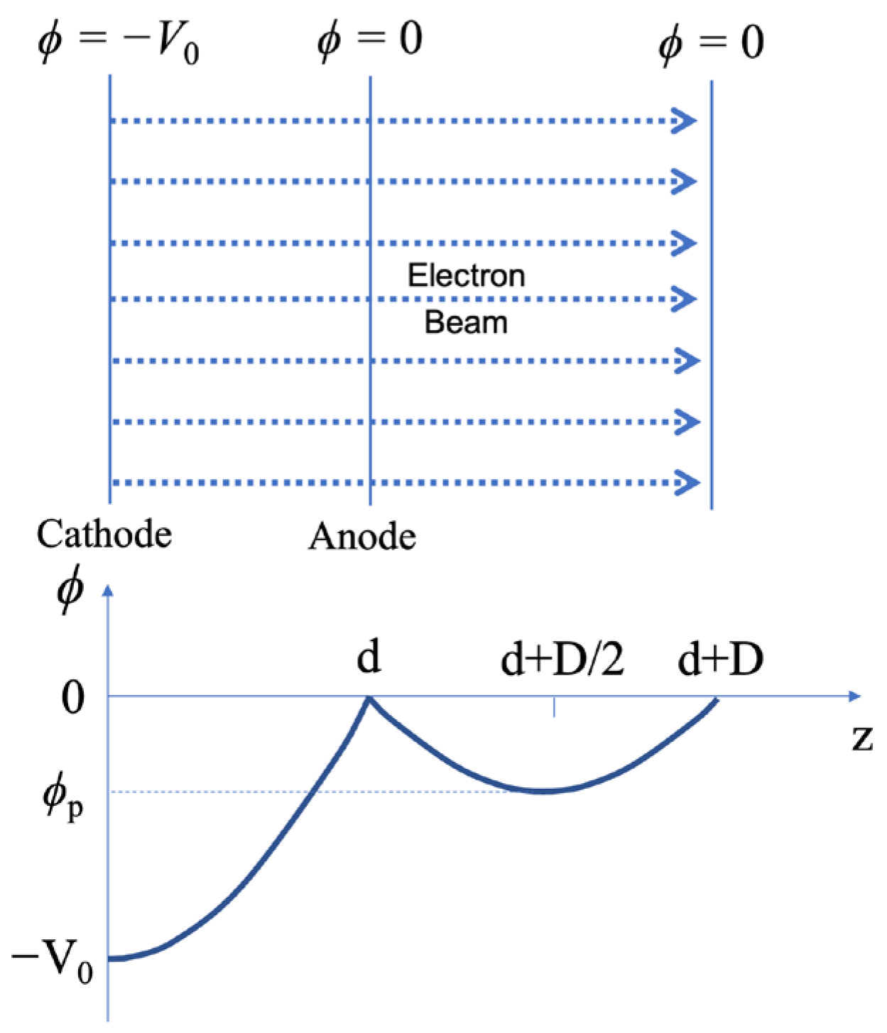
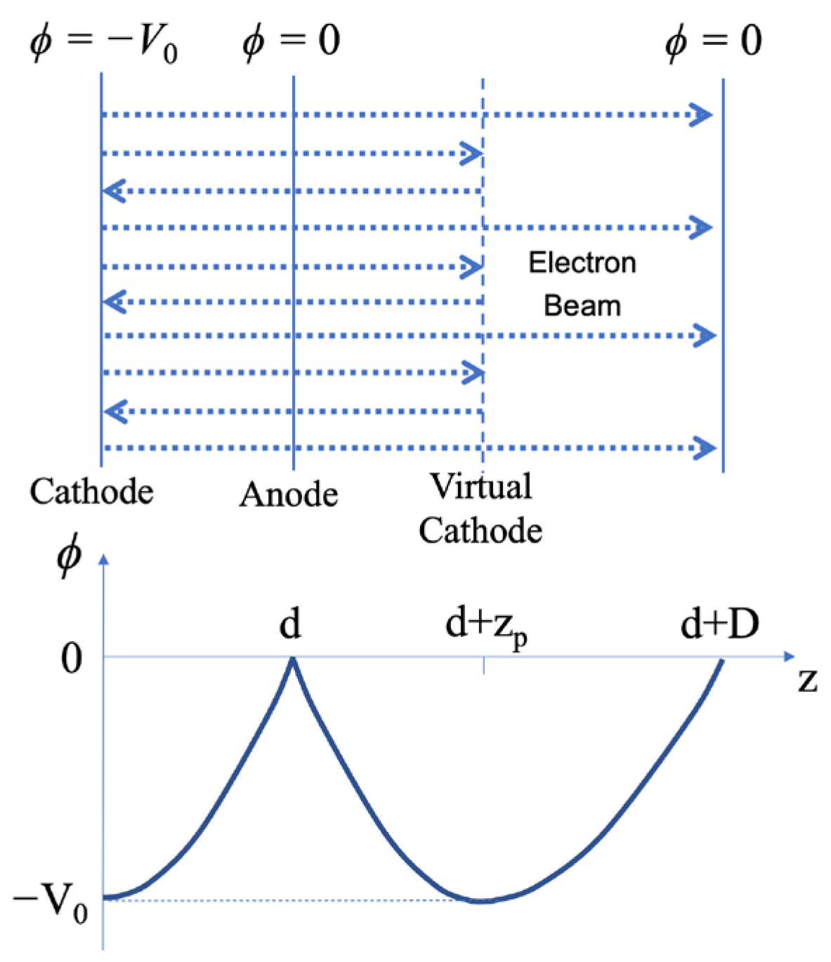
4. An Acceleration Gap and a Drifting Space

We have considered an acceleration gap in Section 2 and a drifting space in Section 3. In this section, we put them next to each other. We consider only the ideal case, where the boundary between two regions is assumed to be 100% transparent to the electrons, which means the beam electrons neither lose their number nor their energy when crossing the boundary.

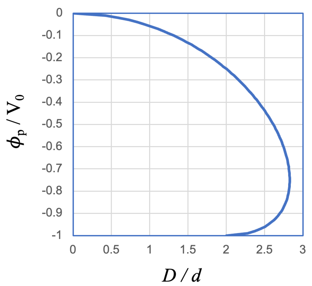
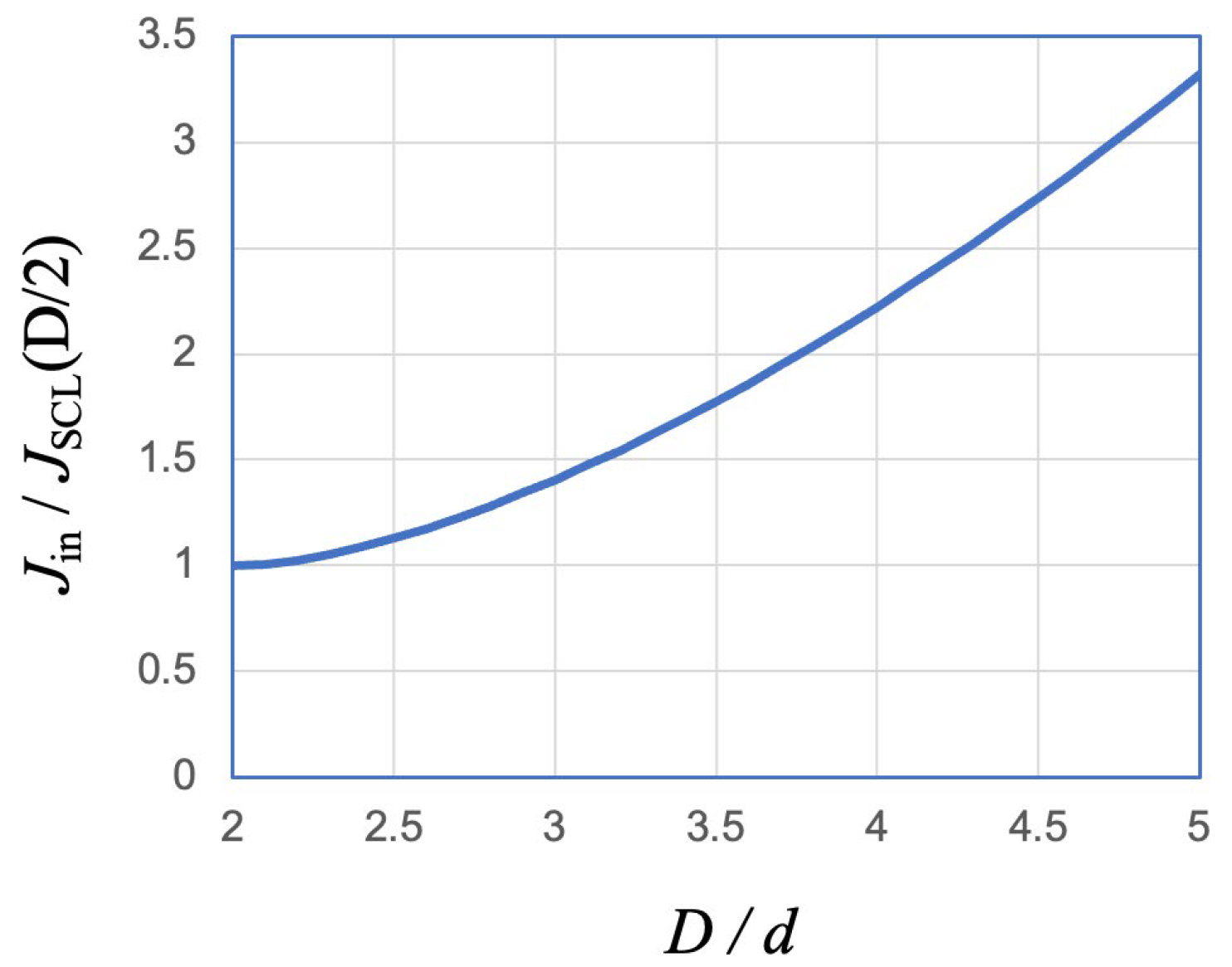
4.1. When the Drifting Space Is Relatively Narrow

In case the width of the drifting space is relatively small so that all electrons injected from the acceleration gap can pass through the drifting space and arrive at the other side, as shown schematically in Figure 11, nothing has changed from the explanations in Section 2.1 and Section 3.1. According to Equation (52), the limit on the width of the drifting space is
J i n J S C L ( D / 2 ) = D 2 d 2 2
or
D 2 2 d 2.83 d
Using Equation (71), Figure 4 is plotted again in Figure 12 in order to show the dependence of the minimum potential on the width of the drifting space. Based on the discussions of Section 3.3, we understand that only the region of −3/4 < ϕp/V0 < 0 is practically meaningful, in which we have 0 < D < 2.83d.

4.2. When the Drifting Space Is Wider Than the Critical Limit

In case the width of the drifting space is wider than the critical limit, which is given by Equation (72), a virtual cathode is formed in the drifting space, which reflects part of the electron beam back to the acceleration gap, as shown in Figure 13. Here, the acceleration gap is no longer an independent electron beam source because the space charge of the reflected electron beam will affect the current of the injected beam.
Under the assumption that the boundary plane (anode) separating two regions is 100% transparent, the sum of the current amplitudes of leftward-going and rightward-going beams is expected to be the same on both sides of the anode between the cathode and virtual cathode. Therefore, since both regions satisfy space-charge-limited condition, we have
z p = d or z p = 1
Namely, the virtual cathode–anode distance equals the cathode–anode distance. Substituting the above relation into Equations (61) and (62), we obtain
J i n + J r e = 4 9
J t r = 4 9 1 D 1 2
and then
2 J i n = J i n + J r e J t r = 4 9 1 + 1 D 1 2
Hence, we can express the following current ratio using distance ratio D/d:
J i n J S C L ( D / 2 ) = 1 8 D d 2 1 + 1 ( D / d 1 ) 2
This relation is plotted in Figure 14. For any given value of d, when D increases, the current ratio Jin/JSCL(D/2) also increases. It is mostly due to the decrease in |JSCL(D/2)|, although the increase in Jre contributes to a mild decrease in |Jin|, according to Equation (74).
According to Equation (70), for the reflected electrons, it takes a total time of 6d/v0 to reach the virtual cathode and then come back to the anode. Therefore, if an electron is moving back and forth between the cathode and the virtual cathode, the period of this oscillatory movement (which is also called reflexing) is given by
t o s c r e f l e x i n g = 12 d v 0
which corresponds to an angular frequency of
ω o s c r e f l e x i n g = π v 0 6 d = π 2 2 ω p
Equations (3), (8) and (27) have been used to derive the above relation. Here, ωp is the so-call beam plasma frequency,
ω p = n b e 2 m ε 0 1 / 2
for electron density at the anode (nb).
Looking again at Figure 14, when Jin/JSCL(D/2) = 2, we have D/d ≈ 3.75. Consequently, for D/d < 3.75, we should have Jin/JSCL(D/2) < 2, which means that, according to Equation (51), the injected current density is lower than the space-charge-limited current of the drifting space. In other words, when D/d < 3.75, the state of the virtual cathode is represented by (c) in Figure 8, which is an unstable state as discussed in Section 3.3.
Therefore, for D ≤ 2.83d, we have steady-state electron flow without reflection, which is represented by state (a) in Figure 8. For D > 3.75d, on the other hand, we have a steady-state solution for the virtual cathode formation in the drifting space, which is represented by state (d) in Figure 8. There is a gap in between which is expressed by
2 2 < D / d < 3.75
For any value of D/d that falls into this gap, there is no possible steady state for complete beam transmission because, in that case, the current would be above the space-charge-limited current of the drifting space. However, in the steady-state virtual cathode model shown in Figure 13, a reflected beam is returned to the acceleration gap, which reduces the injected beam current to a level beneath the space-charge-limited current of the drifting space. This reduced incoming beam tends to pass the drifting space through the transition from state (c) to state (a) of Figure 8, which would cease electron beam reflection in the drifting space. Without the reflected beam, the acceleration gap would inject an electron beam of current amplitude higher than the space-charge-limited current of the drifting space. The above description is clearly a time-dependent process, of which the details are out of the scope of this article. However, it has been made clear that, from the steady-state point of view, we cannot find a stable virtual cathode in the parameter range of Equation (81).
Therefore, when D/d increases slowly from zero, all electrons pass through the drifting space at the beginning. As shown in Figure 15, the minimum potential decreases while staying at the center of the drifting space until D/d reaches ~ 2.83, which is the critical value for complete beam transmission. After this point, a virtual cathode tries to appear somewhere in the drifting space and reflect part of the electron beam back to the acceleration gap. But this situation is not sustainable, as explained above unless D/d exceeds 3.75, which, according to Figure 14, is the condition for Jin/JSCL(D/2) > 2 even when the effect of the reflected beam on the acceleration gap is taken into account.

5. Summary

In this review article, the space-charge effect of electron beams is studied by using one-dimensional steady-state models. Starting from an acceleration gap where electrons with zero initial kinetic energy are accelerated by a constant voltage, the space-charge-limited current has been obtained for both non-relativistic and relativistic cases.
The electron beam transportation through a drifting space is studied for situations with and without virtual cathode formation. An overlap is observed for these two situations of which the one without a virtual cathode is considered to be stable. The virtual cathode formation with injected beam current under space-charge-limited current is considered to be unstable from the steady-state point of view.
When an acceleration gap and a drifting space are connected with each other so that electrons can freely move from one region to another, the electron beam reflected by the virtual cathode in the drifting space can enter the acceleration gap, resulting in reduced injected-beam current due to its space-charge effect. In this situation, there exists a parameter range in which neither can the electron beam injected by the acceleration gap pass the drifting space without reflection, nor can it sustain a stable virtual cathode by exceeding the space-charge-limited current of the drifting space even when reflection occurs.

Funding

This research received no external funding.

Institutional Review Board Statement

Not applicable.

Informed Consent Statement

Not applicable.

Data Availability Statement

No new data was created or analyzed in this study. Data sharing is not applicable to this article.

Conflicts of Interest

The author declares no conflict of interest.

References

  1. Zhang, P.; Valfells, A.; Ang, L.K.; Luginsland, J.W.; Lau, Y.Y. 100 years of the physics of diodes. Appl. Phys. Rev. 2017, 4, 011304. [Google Scholar] [CrossRef]
  2. Harris, J.R.; O’Shea, P.G. Gridded Electron Guns and Modulation of Intense Beams. IEEE Trans. Electron Devices 2006, 53, 2824–2829. [Google Scholar] [CrossRef]
  3. Siman-Tov, M.; Leopold, J.G.; Krasik, Y.E. Self-oscillations in an over-injected electron diode–Experiment and analysis. Phys. Plasmas 2019, 26, 033113. [Google Scholar] [CrossRef]
  4. Humphries, S., Jr. Chapter 5 Introduction to Beam-Generated Forces. In Charged Particle Beams; John Wiley and Sons: Hoboken, NJ, USA, 1990. [Google Scholar]
  5. Miller, R.B. Chapter 3 Propagation of Intense Beams in Vacuum. In An Introduction to the Physics of Intense Charged Particle Beams; Plenum Press: New York, NY, USA, 1982. [Google Scholar]
  6. Sullivan, D.J.; Walsh, J.E.; Coutsias, E.A. Chapter 13 Virtual Cathode Oscillator–(Vircator) Theory. In High-Power Microwave Sources; Granatstein, V.L., Alexeff, I.A., Eds.; Artech House: Boston, MA, USA; London, UK, 1987. [Google Scholar]
  7. Benford, J.; Swegle, J.A.; Schamiloglu, E. Chapter 10 Vircators. In High Power Microwaves, 3rd ed.; CRC Press: Boca Raton, FL, USA, 2016. [Google Scholar]
  8. Valfells, A.; Feldman, D.W.; Virgo, M.; O’Shea, P.G. Effects of pulse-length and emitter area on virtual cathode formation in electron guns. Phys. Plasmas 2002, 9, 2377–2382. [Google Scholar] [CrossRef]
  9. Child, C.D. Discharge from Hot CaO. J. Phys. Rev. Ser. I 1911, 32, 492–511. [Google Scholar] [CrossRef]
  10. Lungmuir, I. The Effect of Space Charge and Initial Velocities on the Potential Distribution and Thermionic Current between Parallel Plane Electrodes. Phys. Rev. 1923, 21, 419–435. [Google Scholar] [CrossRef]
  11. Fay, C.E.; Samuel, A.L.; Shockley, W. On the Theory of Space Charge Between Parallel Plane Electrodes. Bell Syst. Tech. J. 1938, 17, 705–717. [Google Scholar] [CrossRef]
  12. Strutt, M.J.; van der Ziel, A. On Electronic Space-Charge with Homogeneous Initial Electron Velocity between Plane Electrodes. Physica 1938, 5, 705–717. [Google Scholar] [CrossRef]
  13. Jaffe, G. On the Currents Carried by Elections of Uniform Initial Velocity. Phys. Rev. 1944, 65, 91–98. [Google Scholar] [CrossRef]
  14. Bull, C.S.; Birdsall, C.K. Space-Charge Effects in Beam Tetrodes and Other Valves. J. Inst. Electr. Eng.-Part III 1948, 95, 17–24. [Google Scholar]
  15. Page, L.; Adams, N.I. Diode Space Charge for Any Initial Velocity and Current. Phys. Rev. 1949, 76, 381–388. [Google Scholar] [CrossRef]
  16. Klemperer, O. Chapter 8 Electron Optics and Space Charge. In Electron Optics, 2nd ed.; Cambridge University Press: London, UK; New York, NY, USA, 1953. [Google Scholar]
  17. Birdsall, C.K.; Bridges, W.B. Space-Charge Instabilities in Electron Diodes and Plasma Converters. J. Appl. Phys. 1961, 32, 2611–2618. [Google Scholar] [CrossRef]
  18. Bridges, W.B.; Birdsall, C.K. Space-Charge Instabilities in Electron Diodes, II. J. Appl. Phys. 1963, 34, 2946–2955. [Google Scholar] [CrossRef]
  19. Birdsall, C.K.; Bridges, W.B. Chapter 3 Stability of Flow; Nonlinear Solution of Multiparticle Model. In Electron Dynamics of Diode Regions; Academic Press: New York, NY, USA, 1966. [Google Scholar]
  20. Bridges, W.B.; Frey, J.I.; Birdsall, C.K. Limiting Stable Currents in Bounded Electron and Ion Streams. IEEE Trans. Electron Devices 1965, 12, 264–272. [Google Scholar] [CrossRef]
  21. Jory, H.R.; Trivelpiece, A.W. Exact Relativistic Solution for the One-Dimensional Diode. J. Appl. Phys. 1969, 40, 3924–3926. [Google Scholar] [CrossRef]
  22. Prono, D.S.; Creedon, J.M.; Smith, I.; Bergstrom, N. Multiple reflections of electrons and the possibility of intense positive-ion flow in high v/γ diodes. J. Appl. Phys. 1975, 46, 3310–3319. [Google Scholar] [CrossRef]
  23. Miller, P.A.; Halbleib, J.A.; Poukey, J.W. Inverse ion diode experiment. J. Appl. Phys. 1981, 52, 593–598. [Google Scholar] [CrossRef]
  24. Neumann, J.G.; Harris, J.R.; O’Shea, P.G. Production of photoemission-modulated beams in a thermionic electron gun. Rev. Sci. Instrum. 2005, 76, 033303. [Google Scholar] [CrossRef]
  25. González, G.; González, F.J. A novel approach to the Child-Langmuir law. Rev. Mex. Fís. E. 2017, 63, 83–86. [Google Scholar]
  26. Leopold, J.G.; Siman-Tov, M.; Goldman, A.; Krasik, Y.E. Over-injection and self-oscillations in an electron vacuum diode. Phys. Plasmas 2017, 24, 073136. [Google Scholar] [CrossRef]
  27. Mahaffey, R.A.; Sprangle, P.; Golden, J.; Kapetanakos, C.A. High-Power Microwave from a Nonisochronic Reflecting Electron System. Phys. Rev. Lett. 1977, 39, 843–846. [Google Scholar] [CrossRef]
  28. Kwan, T.J.T. High-Efficiency, Magnetized, Virtual-Cathode Microwave Generator. Phys. Rev. Lett. 1986, 57, 1895–1898. [Google Scholar] [CrossRef] [PubMed]
  29. Benford, J.; Price, D.; Sze, H.; Bromley, D. Interaction of a Vircator Microwave Generator with an Enclosing Resonant Cavity. J. Appl. Phys. 1987, 61, 2098–2100. [Google Scholar] [CrossRef]
  30. Jiang, W.; Masugata, K.; Yatsui, K. Mechanism of Microwave Generation by Virtual Cathode Oscillation. Phys. Plasmas 1995, 2, 982–986. [Google Scholar] [CrossRef]
  31. Jiang, W.; Woolverton, K.; Dickens, J.; Kristiansen, M. High Power Microwave Generation by a Coaxial Virtual Cathode Oscillator. IEEE Trans. Plasma Sci. 1999, 27, 1538–1542. [Google Scholar] [CrossRef]
  32. Jiang, W.; Kristiansen, M. Theory of the Virtual Cathode Oscillator. Phys. Plasmas 2001, 8, 3781–3787. [Google Scholar] [CrossRef]
  33. Selemir, V.D.; Dubinov, A.E.; Voronin, V.V.; Zhdanov, V.S. Key Ideas and Main Milestones of Research and Development of Microwave Generators With Virtual Cathode in RFNC-VNIIEF. IEEE Trans. Plasma Sci. 2020, 48, 1860–1867. [Google Scholar] [CrossRef]
Figure 1. One-dimensional model of an acceleration gap where electrons, with certain space charge, are accelerated by the gap voltage from zero initial kinetic energy. The lower graph is a conceptual illustration of the electric-potential distribution.
Plasma 07 00003 g001
Figure 2. Numerically calculated values of G using Equation (41).
Plasma 07 00003 g002
Figure 3. One-dimensional model of a drifting space where an electron beam is injected with initial electron kinetic energy of eV0. Here, the beam current density is relatively low.
Plasma 07 00003 g003
Figure 4. Dependence of ϕp on Jin/JSCL(D/2), as expressed in Equation (49).
Plasma 07 00003 g004
Figure 5. One-dimensional steady-state model of a drifting space where an electron beam is injected with initial electron kinetic energy of eV0. Here, the beam current density is higher than the critical value given by Equation (51).
Plasma 07 00003 g005
Figure 6. Relation between the injected beam current density (Jin) and the position of the virtual cathode (zp), as expressed by Equation (65).
Plasma 07 00003 g006
Figure 7. Dependence of Jre/Jin and Jtr/Jin on Jin, given by Equations (66) and (67).
Plasma 07 00003 g007
Figure 8. Replot of Figure 4 by adding the constant virtual cathode potential at −V0.
Plasma 07 00003 g008
Figure 9. Schematic illustration of electron beam states marked by (ac) in Figure 8.
Plasma 07 00003 g009
Figure 10. Total charge (per unit area) of electrons in the drifting space, calculated by using Equations (55) and (68), for states (a), (b), and (c) of Figure 8.
Plasma 07 00003 g010
Figure 11. One-dimensional model of an acceleration gap in conjunction with a drifting space. Here, the drifting space is relatively narrow.
Plasma 07 00003 g011
Figure 12. Dependence of ϕp on D/d, which is physically equivalent to that shown in Figure 4.
Plasma 07 00003 g012
Figure 13. One-dimensional model of an acceleration gap in conjunction with a drifting space. Here, the drifting space is wide enough that a virtual cathode is formed in it.
Plasma 07 00003 g013
Figure 14. Dependence of Jin/JSCL(D/2) on D/d, obtained using Equation (77).
Plasma 07 00003 g014
Figure 15. Dependence of ϕp/V0 and zp/d on D/d obtained using the model shown in Figure 13. In the region marked “UNSTABLE”, the virtual cathode is in the state represented by (c) in Figure 8.
Plasma 07 00003 g015
Disclaimer/Publisher’s Note: The statements, opinions and data contained in all publications are solely those of the individual author(s) and contributor(s) and not of MDPI and/or the editor(s). MDPI and/or the editor(s) disclaim responsibility for any injury to people or property resulting from any ideas, methods, instructions or products referred to in the content.

