Article

Penetration of a Pulsed Guided Streamer Discharge into Micrometer-Sized Capillary Tubes

Department of Mechanical Engineering, University of Minnesota, Minneapolis, MN 55455, USA
*
Author to whom correspondence should be addressed.
Plasma 2023, 6(4), 663-679; https://doi.org/10.3390/plasma6040046
Submission received: 20 August 2023 / Revised: 16 October 2023 / Accepted: 30 October 2023 / Published: 1 November 2023
(This article belongs to the Special Issue Feature Papers in Plasma Sciences 2023)

Abstract

:
The penetration and propagation of streamers in capillary tubes is critical for applications involving the plasma-enabled disinfection of medical devices like catheters and plasma catalysis. In this study, a guided streamer is generated in a pulsed plasma jet operating in helium and impinged downstream onto a capillary tube with an inner diameter between 75 and 500 µm. The threshold voltage required to start the penetration of the guided streamer into the capillary was determined for both positive and negative polarities, and we observed a time delay between the streamer striking the top of the capillary and its penetration, which was found to be larger for the positive than the negative streamer. The observed differences can be explained by the need to sustain an electric field large enough to generate a sufficient seed electron density in the capillary to launch the streamer. The reported results suggest that the electric field at the capillary inlet is likely reduced by the formation of strong surface ionization waves for positive streamers. Nonetheless, in the case of positive streamers, the formation of surface streamers along the outside of the capillary wall can enhance streamer penetration into the capillary and the streamer propagation speed.

Graphical Abstract

1. Introduction

Atmospheric pressure plasma jets (APPJs) have been extensively studied in the last two decades due to their large range of possible applications in decontamination [1], health care [2,3], and material synthesis and processing [4,5]. Plasma generation in APPJs typically occurs in a capillary tube through which a noble gas such as helium is flown. The helium effluent of the jet enables the generation of guided streamers or plasma effluents that can propagate into an open-air surrounding [6] and generate a large flux of reactive species onto a variety of substrates which enables the above applications [7]. The resulting guided streamers can also propagate in capillary tubes with large aspect ratios, which enable the decontamination of endoscopes, catheters, and root canals of teeth [8,9,10]. In addition, the penetration of plasmas into high aspect ratio pores of catalysts is believed to be important for synergy reported in plasma catalysis [11]. One approach in catalysis is the use of monoliths to support catalysts, and in this case, the penetration of plasma in micrometer-sized channels is critical [12]. A better understanding of the penetration of streamers into capillaries with submillimeter diameters and subsequent streamer propagation has the potential to advance both decontamination applications in high aspect ratio capillaries and enhance the conversion of chemicals in plasma catalysis applications.
The penetration and propagation of plasma discharges in capillaries with a submillimeter diameter benefit from high electric fields and small plasma dimensions, as found in streamer discharges. Streamer discharges are plasma filaments that can propagate in an electric field lower than the electrical breakdown field due to the electric field enhancement by the streamer head. The electric field produced by the streamer can be much higher than the breakdown field due to the small dimensions of the plasma channel (typically ~100 µm in air) [13]. In most situations, streamer channels branch and produce seemingly random structures [14]. However, streamers generated in plasma jets can form highly repeatable and reproducible “guided streamers” or plasma bullets due to their “confinement” in noble gas jets. This confinement is enabled by the significantly larger Townsend ionization coefficient in helium and argon compared to the surrounding air, which localizes the discharge in the gas channel [6,15,16]. The guided streamers are formed in two stages. First, an ionization wave is formed in a strong electric field region inside the dielectric tube, and it propagates along the tube walls. In the second stage, the gas channel acts as an extension of the capillary tube in which the streamer is generated in the jet [15]. This “confinement effect” is further enhanced by the formation of negative ions from O2 in the air that surrounds the noble gas channel. As these anions have much lower mobility than the electrons and the electric field produced by these anions focuses the movement of the electrons on the axis of the helium jet, a guided streamer can be sustained at larger distances from the jet nozzle in the air compared to an N2 surrounding [17].
The characteristics of streamers significantly depend on the polarity of the applied voltage to the high-voltage electrode generating the streamer [14]. This difference is mainly due to the direction of electron motion compared to the streamer propagation direction. For a positive streamer (generated by a positive high-voltage pulse at the high-voltage electrode), the electrons produced by the high electric field in front of the streamer head are driven into the streamer by the electric field. However, for a negative streamer (generated by a negative high-voltage pulse at the high-voltage electrode), the electron motion is in the same direction as the streamer propagation. This leads to a broader radial spread of the electrons for negative compared to positive streamers and a tendency to increase the radius of the streamer head and hence reduce the local electric field. While positive streamers often rely on photoionization to generate electrons in front of the streamer head, the stronger electric field in positive streamers compared to negative streamers enhances the production of “seed electrons” and facilitates streamer propagation [18]. The above differences can, for example, explain the 3 cm long positive streamer compared to the 1 cm long negative streamer generated by plasma jets, as reported by Jiang et al. [19].
The generation and propagation of streamers and ionization waves in a micrometer-sized capillary have also been extensively studied. Ning et al. [20] and Wu et al. [21] reported that the voltage at which streamers are generated in capillary tubes can significantly increase with reducing capillary diameters (below 1 mm). While most modeling studies of the penetration of pulsed plasmas enable penetration in submillimeter capillary tubes on timescales of the streamer propagation in ambient conditions [11,12], an experimental study for an RF-driven plasma jet penetrating into capillaries reports significant time delays before plasma penetration into the capillary was observed [9]. It was shown that it may take several RF cycles before penetration is observed after argon and helium RF-driven plasma jets impinge on capillaries with a diameter of ~500 µm. This finding was explained by the lower electrical field in RF discharges compared to pulsed plasma jets and the requirement to build up sufficient metastable species and electron densities to enable the increase in the ionization rate by Penning and stepwise ionization [9]. These findings further underline the importance of sufficient seed electrons for discharge initiation, particularly in capillaries with small diameters in which the radial electron loss to the wall can become important compared to the volume losses, as highlighted in modeling studies [22].
The characteristics of a streamer propagating through a capillary tube are similarly highly influenced by the formation of seed electrons in the capillary. Kruszelnicki et al. [23] reported that for humid air APPJs, the ions produced by photoionization are an important factor in producing seed electrons and are required to facilitate streamer propagation in a high aspect ratio pore in a catalyst pellet. Ning et al. [22] concluded that the rapid diffusion of the electrons to the dielectric walls, particularly for smaller capillary diameters, not only reduces the electron density but can also ultimately inhibit streamer propagation. Nonetheless, Jánský et al. [24,25] reported that the average velocity of the streamer propagating through a capillary increases with decreasing capillary diameter. This suggests an enhancement of the streamer due to surface charges, similar to the negative ion density surrounding the helium gas channel of the jet in open air, as mentioned above.
While modeling studies have provided significant insights into plasma penetration in high aspect ratio pores and capillaries, few detailed experimental studies have been reported on this topic to date. In this work, we report a systematic study of the penetration of a 500 ns pulsed helium plasma jet into a capillary tube with submillimeter diameters, including the subsequent propagation of the streamer through the capillary. We report not only the constraints on the capillary diameter for penetration and propagation of the streamer but also explore the impact of discharge polarity in detail. The observed trends for the different plasma jet conditions allow us to explore in more detail the underpinning mechanisms and identify key parameters that impact the observed phenomenon.

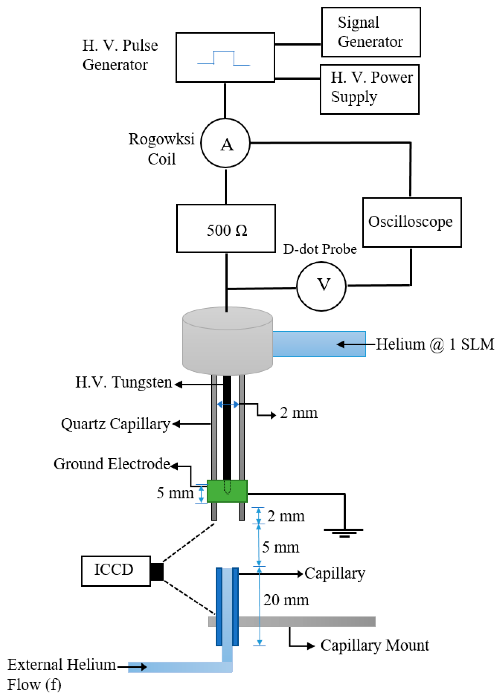
2. Materials and Methods

The plasma jet used for the experiments reported in this work is schematically shown in Figure 1. The plasma jet consists of a quartz tube with an inner diameter of 2 mm, a tungsten electrode with a diameter of 1 mm, and a cylindrical grounded electrode with a height of 5 mm on the outside of the quartz tube. The distance between the lower edge of the cylindrical electrode and the quartz tube nozzle was 2 mm. The tip of the high-voltage electrode is in the center of the cylindrical grounded electrode. A continuous helium gas flow at 1 standard liter per minute (slm) was maintained via the quartz tube using a mass flow controller (MKS GE50, USA).
The plasma was generated by applying high-voltage pulses to the tungsten needle electrode. The applied voltage pulses had a pulse width of 500 ns, a voltage amplitude between 1.5 kV and 5.5 kV, and a fixed pulse repetition rate of 1 kHz. The rise time of the high-voltage pulse is approximately 25 ns, although it can be larger in certain cases due to the observed oscillations. Both positive and negative polarity voltages were investigated. The high-voltage pulses were generated using a high-voltage pulser (DEI PVX 4110, USA). A signal generator (Tektronix AFG2021, USA) enabled voltage pulse generation. A DC high-voltage power supply (Glassman PS/FJ10P12 and PS/FJ10N12, USA) was used as input for the high-voltage pulser. The current and voltage waveforms were measured by a Rogowski coil (Pearson Electronics 2877) and a homemade d-dot using an oscilloscope (Berkeley Nucleonics Corp. Model P2025, USA). The d-dot was calibrated using a high-voltage probe (Tektronix P6015A, USA), measuring the voltage of applied voltage pulses without plasma generation at the same location as the d-dot in the setup. The time delay between the voltage and current probe was measured and corrected.
The study focused on the penetration and propagation of the plasma jet into Pyrex glass capillary tubes with a diameter ranging from 500 μm to 75 μm. The length of the capillaries was kept constant at 20 mm. The jet impinged on capillaries mounted on a support structure to allow for the alignment of the capillary with the jet via translation stages in 3 dimensions with a spatial resolution of 0.1 mm. The distance between the jet nozzle and the capillary was kept at 5.5 mm, 7 mm, and 10 mm. An external helium flow was applied from the bottom of the capillaries. The helium flow in this external capillary tube was fixed at 30 standard cubic centimeters per minute (sccm) by a mass flow controller (MKS GE50) unless otherwise mentioned. This gas flow enhanced the reproducibility of the measurements by providing a well-defined gas composition in the capillary.
The plasma dynamics were imaged using an intensely charged coupled device (ICCD, Andor Technology iStar DH340T, USA) with a lens (Navitar, Zoom 7000, USA). The ICCD camera was triggered using the TTL output connected to the signal generator, which was used to trigger the high-voltage pulser to synchronize imaging with the voltage pulse generation. The gate width was kept constant at 10 ns throughout the work, and each image consisted of 15 accumulations.

3. Results

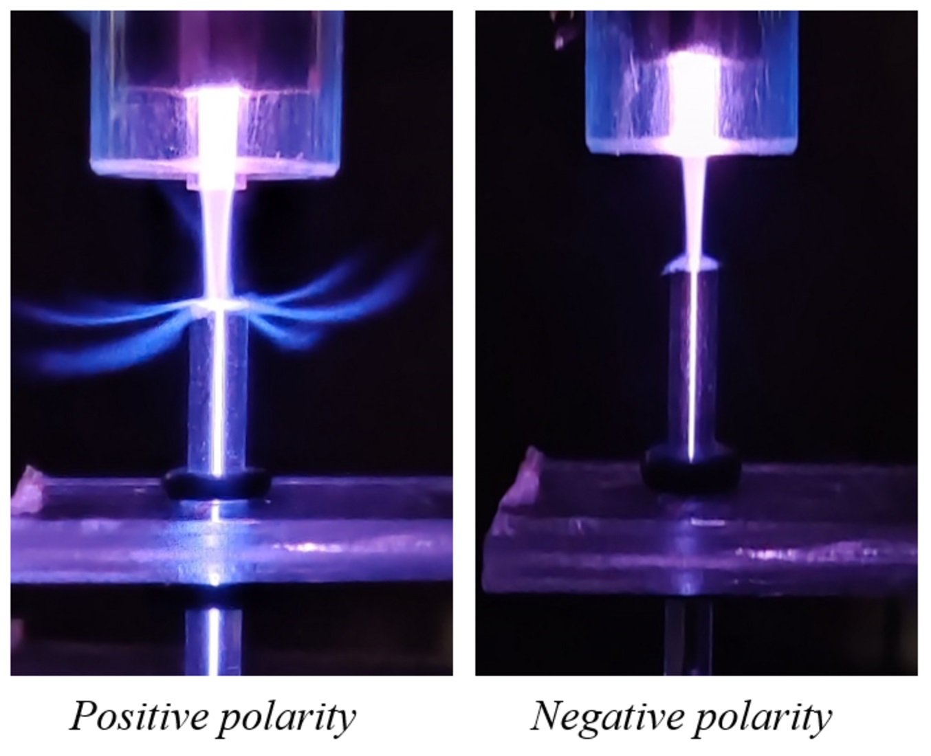
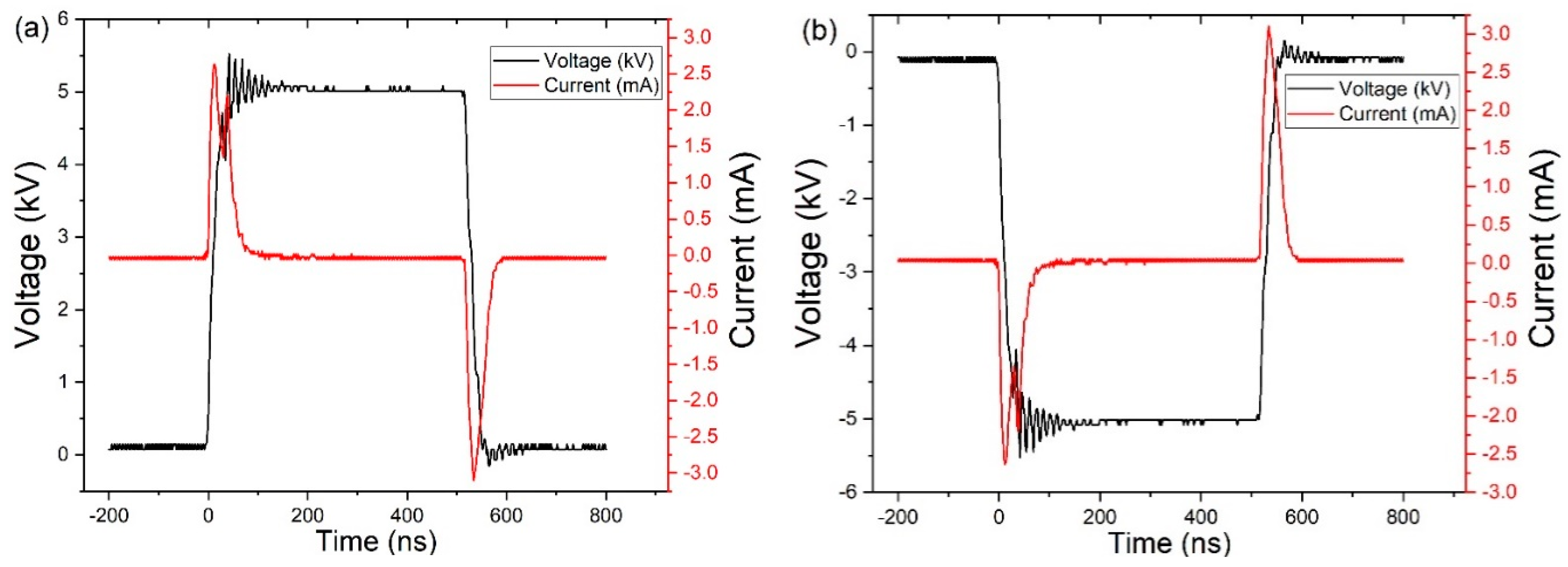
3.1. Plasma Characteristics

The current and voltage waveforms of the free plasma jet, as shown in Figure 2, suggest that the current is dominated by displacement current, indicating that the plasma jet is highly capacitive. The energy per pulse is calculated by integrating the product of the voltage and current waveforms and is E = 41.7 ± 1.8 μJ and E = 27.5 ± 1.2 μJ for the positive and negative polarity streamer in the free jet case, respectively. A larger energy deposition for the positive polarity is consistent with previous observations by van Doremaele et al. [26], who suggested a larger charge deposition on a dielectric substrate for positive polarity jets.
The energy per pulse for a voltage amplitude of 5 kV (both positive and negative polarity) and three different nozzle-to-capillary distances is shown in Figure 3. In the case of positive polarity, the deposited energy in the plasma is smaller for the 5 and 7 mm distance compared to the free jet. This could suggest that it requires less energy to generate a discharge on the surface or inside of the capillary than sustaining a guided streamer in the free jet. Nonetheless, a significant increase of 13 ± 1.2 μJ in deposited energy was observed when increasing the distance between the quartz tube nozzle and the capillary tube from 7 mm to 10 mm, at which we approach an energy per pulse more consistent with the free jet. In the case of negative polarity, the energy deposited by the streamer increases in the presence of a capillary compared to the free jet but seems not strongly dependent on the distance between the nozzle and capillary tube for the investigated distance range. Table 1 reports typical plasma parameters for a helium-pulsed free plasma jet as reported in the literature. The gas temperature remains in good approximation at room temperature. The electron temperature in the guided streamer was reported to be in the range of 0.9–1.5 eV, as obtained by Thomson scattering measurements [27]. Typical electron densities for both positive and negative polarity-free jets were taken from the simulation results and are very similar [28]. Based on these data, the Debye length for the guided streamers can be estimated to be <3 μm. A sheath thickness will typically be an order of magnitude larger than the Debye length and hence will be of the same order of magnitude as the minimum capillary diameter of 75 μm used in this study. This suggests that we anticipate finding conditions for which streamers are able to penetrate into the capillary tubes and, at least for the smaller capillary diameters, a significant impact on the streamer propagation.

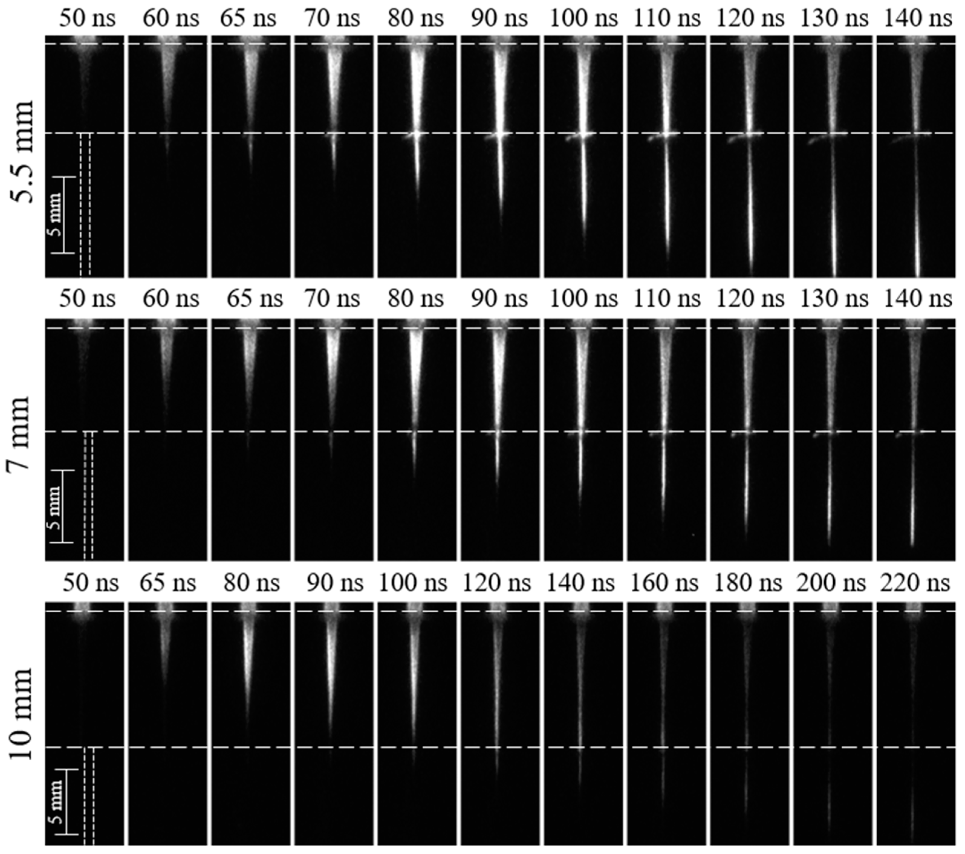
3.2. Overview of the Streamer Penetration and Propagation through the Capillary

Figure 4 shows the vertical position of the streamer head as a function of time when it passes through capillaries with an internal diameter of 150 μm, 250 μm, and 500 μm. The distance traveled by the streamer inside the capillary is considered after the streamer has traversed 1 mm to reduce the uncertainty induced by the strong emission near the top of the capillary. The streamer propagation speed calculated from the slope of the curves in Figure 4 is shown in Table 2. The delays in streamer penetration in the capillaries are also included in Table 2. The uncertainty on the delay is due to the 10 ns resolution of the ICCD gate, and the uncertainty on the propagation speed is determined from the linear fit shown in Figure 2.
The obtained results shown in Table 2 suggest a strong impact on the polarity of the applied voltage and the capillary diameter on the streamer penetration and propagation in capillaries. We report a detailed and systematic analysis of the impact of the operational parameters on the streamer penetration delays and propagation speeds in the next section with the goal of explaining the observed phenomena.

3.3. Guided Streamer Penetration into Capillary Tubes

Figure 5 shows the threshold voltages for guided streamer penetration into capillary tubes as a function of the capillary diameter for different jet nozzle–capillary tube distances. The results show that the impact of helium flow through the capillary is negligible for flow rates between 10 and 30 sccm. Key differences in the threshold voltages between positive and negative guided streamers were observed. Positive streamer penetration is strongly dependent on the capillary diameter but is in good approximation independent of the distance between the jet nozzle and capillary tube for the investigated range up to a distance of 10 mm. On the other hand, the voltage threshold of penetration of negative streamers into the capillary has a significant dependence on distance, while the dependence on the capillary diameter is less pronounced.
Modeling studies have shown that the key factor that prevents the discharge from penetrating into microchannels is insufficient seed electrons [11]. Jánský et al. [24] reported that a higher electron density is required to develop a streamer in the capillary compared to conditions without the capillary. The electrons produced in the gas tend to migrate to the capillary wall, which will increase the electric field and reduce electron losses to the wall over time. This will allow the building up of sufficient electron density to enable the formation of an ionization wave in the capillary channel. The observed delay between impinging of the streamer on the capillary surface and penetration, as shown in Table 2 and Figure 5 and Figure 6, is consistent with this process and the requirement for a critical density of seed electrons to form a streamer in the capillary. Such a delay has already been reported for RF plasma jets. It was argued in this case that for the low electric fields (~3 kV cm−1) in RF-driven jets, Penning and/or stepwise ionization are likely dominant [9] and require a build-up of electrons and metastable species to increase the ionization rate coefficient in the capillary as already mentioned in the introduction. Here, we show that a similar delay is present for pulsed guided streamers that are expected to have higher electric fields in the streamer head, as shown in Table 2.
The characteristic diffusion time of the electron loss to the wall before a space charge layer is built up can be estimated as
τ d i f f = ( R 2.4 ) 2 D e
where R is the radius of the capillary and De is the electron diffusion coefficient. The values for the electron diffusion coefficient were calculated for the electron temperature range mentioned in Table 1 using BOLSIG+ [29]. For a capillary of diameter of 150 μm, the diffusion time scale was estimated to be between 28 and 37 ns. Drift transport timescales are highly dependent on the electric field but could be even faster for electric field amplitudes reported in the streamer head. These timescales are similar to the observed delay times, suggesting that surface charge build-up is likely an important factor for the smaller diameter capillaries investigated in this study.
The observed delays on a timescale between 10 and 70 ns reported in Table 2 and Figure 5 and Figure 6 require that the electric field at the capillary inlet is sustained for such duration after impingement of the plasma jet. The delay in streamer penetration is larger for positive polarity as compared to negative polarity, with a delay of 66 ns for a capillary of 150 μm in the case of positive polarity. The impact of capillary diameter on the delay time seems minimal in the case of negative streamers, as delays remain around 15 ns.
The different penetration behavior for positive and negative streamers finds its origin in the different dynamics and morphology of the positive and negative streamers and the resulting differences in electric fields. The positive streamer head in the helium gas channel between the jet nozzle and the capillary has the shape of a bullet, as shown in Figure 6, while the negative streamer resembles the shape of a sword, as shown in Figure 7. The positive streamer leads to the formation of strong surface ionization waves that are formed without observable delay and hence on a faster timescale than the observed penetration. The radial propagation of the surface ionization waves/streamers will cause a fast reduction in the electric field on the axis of symmetry [30], which will reduce the electric field values near the capillary entrance and slow down the formation of a new ionization wave in the capillary.
The negative streamer results in weaker surface streamer formation on the capillary surface consistent with the lower electric field in the streamer head (Naidis et al. [28], Table 1) and the smaller energy deposition of the free jet. This suggests a smaller amount of surface charge deposition by the negative streamer compared to the positive streamer [26]. This seems, at first sight, inconsistent with the shorter delay in penetration found for negative compared to positive streamers (Table 2). However, the likely larger sustained electric field after streamer impingement is consistent with the higher reported electric field in the streamer channel for negative compared to positive streamers in free jets [28]. Another key difference between positive and negative streamers is that the positive streamer head attracts electrons, while the negative streamer repels electrons [31]. This likely leads to less diffusion of seed electrons into the capillary channel for positive streamers and is consistent with larger penetration delays found for positive streamers than for negative streamers.
The increase in the voltage threshold for penetration with decreasing capillary diameter for positive streamers is consistent with increased radial losses requiring an increase in the applied voltage to produce the streamer in the capillary (Figure 5a). The increase in energy for longer nozzle–capillary distances for positive polarity might compensate for losses during the streamer propagation in the jet effluent, which might explain the limited dependence of the voltage threshold on the penetration in the capillary tube. The increased voltage threshold for penetration for increasing distances between the jet nozzle and capillary for the negative streamer (Figure 5b) is consistent with a decreasing charge and electric field for increasing streamer length and is consistent with the smaller amount of charge transfer in negative streamers [32]. However, when radial electron losses increase for the smaller diameters, the limiting factor becomes the sustainment of a sufficiently high electric field during the delay of penetration, which is, as described above, favored in negative streamers. The increased voltage threshold for penetration for increasing distances between the jet nozzle and capillary for the negative streamer (Figure 5b) is consistent with a decreasing charge and electric field for increasing streamer length when the overall deposited energy is constant, as has been found in the modeling of the free jet [28].

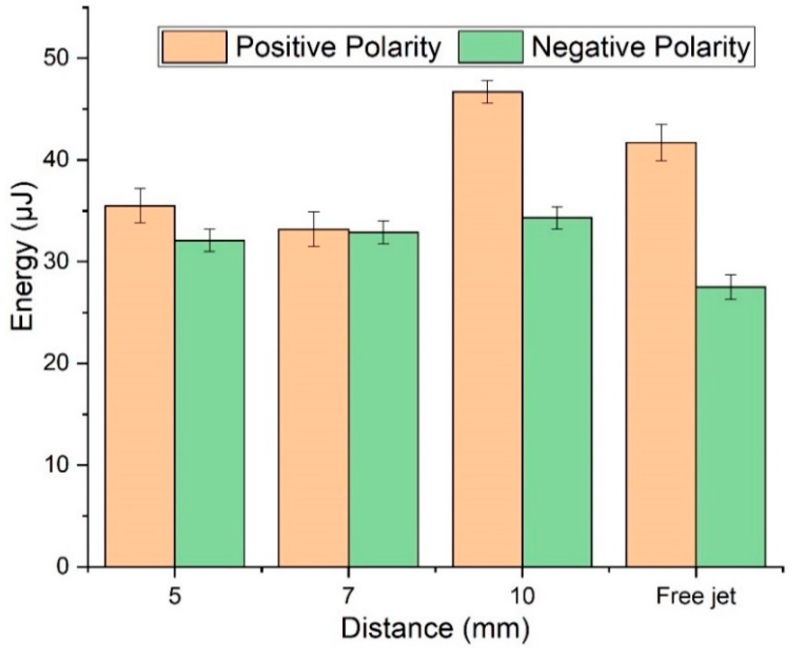
3.4. Streamer Propagation in Capillary Tubes

Some key trends in the speed of the streamer propagation can be readily deduced from Figure 4 and Table 2. A positive streamer propagates faster than the negative streamer in the free jet case, consistent with the higher electric field in the positive streamer head compared to the negative streamer head (Table 1). At a constant voltage, the streamer propagation decreases with decreasing capillary diameter for both polarities. In the case of positive polarity, the speed of the streamer is almost one-third of the speed of the free jet for a capillary diameter of 150 μm. The speed reduction is almost half the streamer propagation speed in the free jet in case of negative polarity. While the streamer propagation for positive streamers is typically larger than for negative streamers, this difference in propagation speed dependence on capillary diameters causes the streamer propagation speed for positive polarity streamers to be smaller than for negative polarity streamers for a 150 μm capillary diameter.
Jánský et al. [25] reported that the streamer head profile for the large capillaries is tubular, but it becomes uniform for smaller capillaries. They also found that for streamers in air, the propagation speed increases with decreasing capillary diameter, opposite to what is found in this work. However, while no Abel inversion was performed on the data, we have not observed a tubular streamer structure and hence the transition from tubular to homogeneous discharge in the capillary tube, which likely caused their reported trend in propagation speed, does not seem to occur for the investigated conditions in our work. Nonetheless, other differences between the model and experiment exist, including different electrode geometries, which could contribute to the discrepancy in the results.
Scaling laws between streamer propagation velocities and streamer diameters have been reported for streamers in the air by Naidis [33], yielding a linear relationship. Given that the capillary diameter is a good estimate of the streamer radius, this relationship seems to hold (see Table 2). A simple correlation between streamer diameter (lp) and propagation speed (vs) has been proposed by Loeb [34],
v s = l p   ν ¯ i ln ( n h / n i d )
where ν ¯ i is the mean ionization frequency in the ionization region near the streamer head, n i d is the number density of seed electrons, and n h is the electron density in the streamer channel. Neglecting small variations in densities because of the logarithmic dependence suggests that the streamer propagation speed scales with the product of capillary diameter and   ν ¯ i . As for the positive streamer case (Table 2), the ratio of v s over l p is constant, and the electric field in the streamer head should be in good approximation constant. Wu et al. [35] previously found that the electric field does not vary much for a capillary diameter of 600 µm and 1 mm. Our findings suggest that this finding might be valid for even smaller capillary diameters. While this scaling law is based on a simplified picture of streamers, it has been previously shown to be able to describe guided streamers in helium rather well [36].
What remains to be explained is the smaller dependence of the streamer speed on the capillary diameter for negative streamers than for positive streamers. A key difference between positive and negative streamers is related to surface charging on the dielectric inner wall of the capillary. When a positive streamer propagates through the capillary channel, it attracts electrons, leading to a positive surface charge on the capillary walls [24]. This positive surface charge is not conducive to streamer propagation, and the streamer will need to fully rely on its own electric field to sustain propagation. This is also likely the reason why the above scaling law can describe our findings. However, negative streamers repel electrons and cause the generation of a negatively charged sheath layer near the capillary walls [24]. This surface charge reduces the radial electron losses and helps focus the electrons in the propagation direction consistent with a smaller impact of the tube radius on the negative streamer propagation speed.
Figure 8 shows that the streamer propagation speed decreases with increasing distance from the jet nozzle to the capillary, consistent with the smaller electric field for increasing distance. The propagation speed for positive streamers is less dependent on the distance between the jet nozzle and capillary, consistent with the smaller impact of this distance on the penetration threshold voltage.

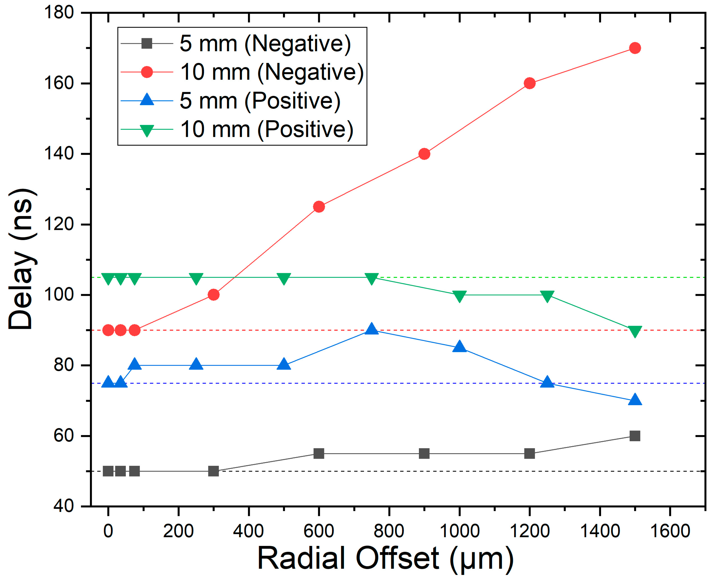
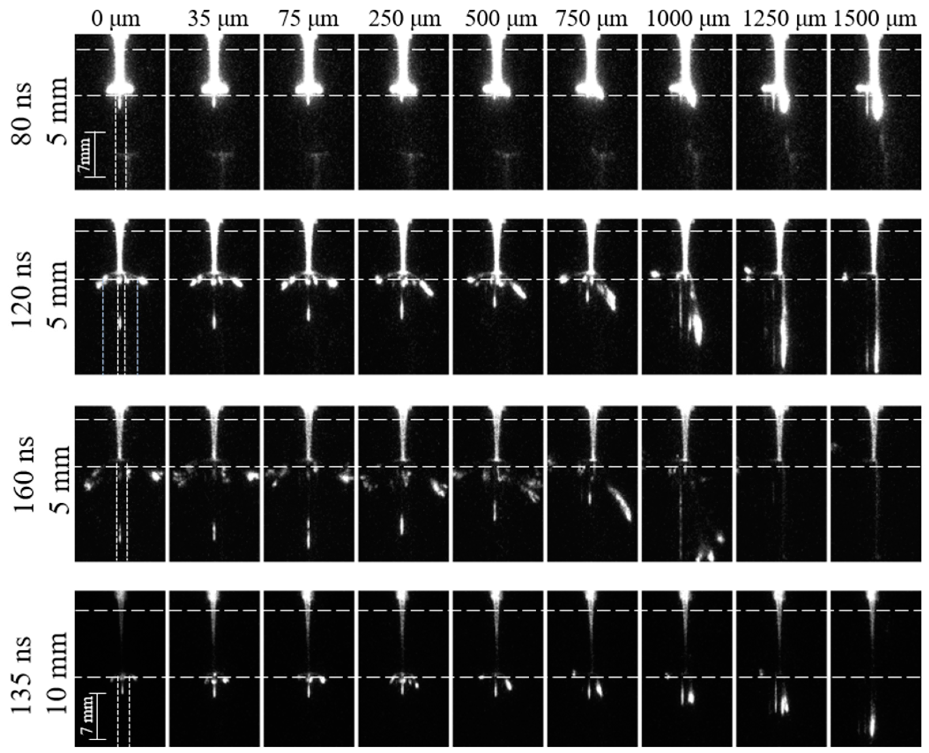
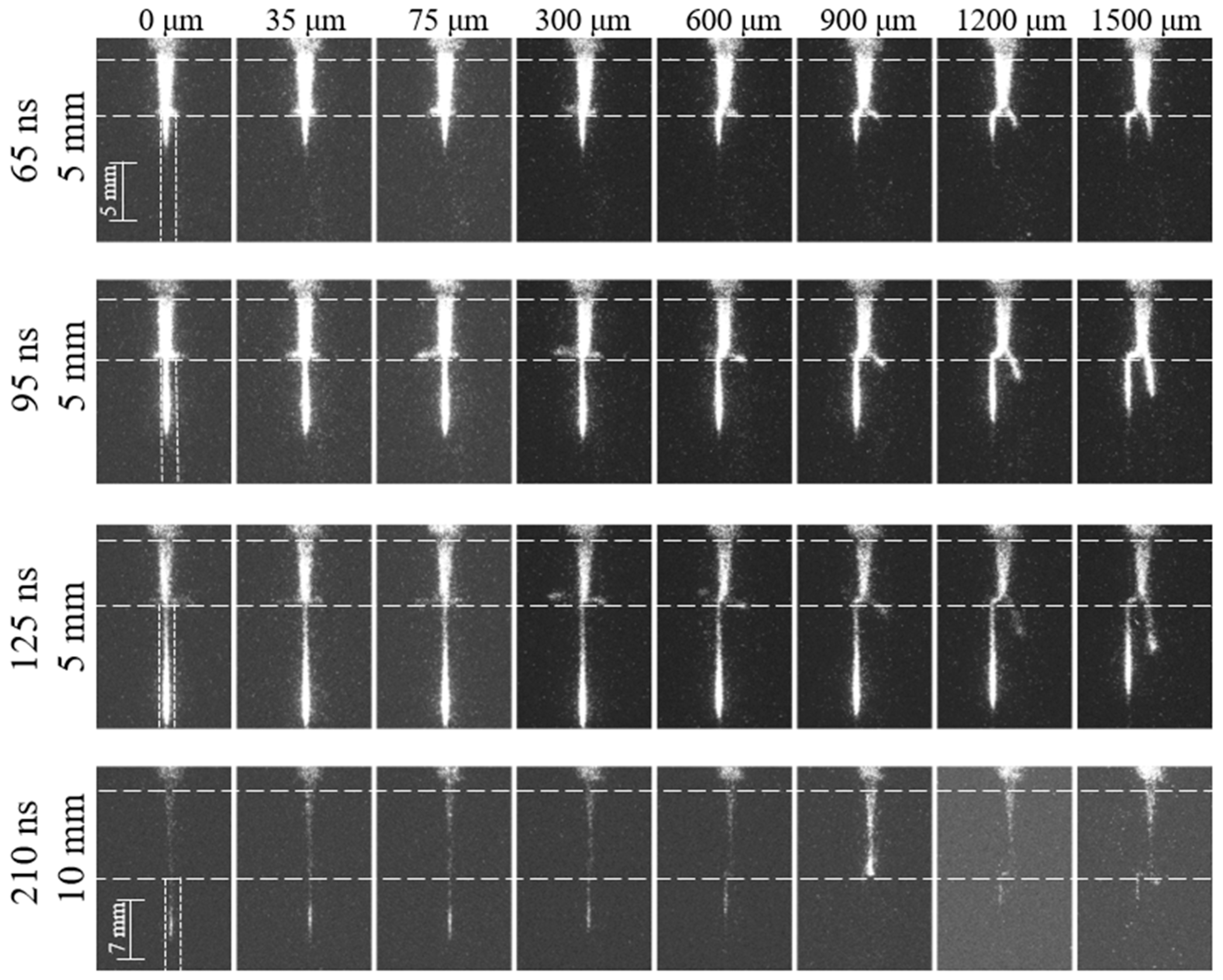
3.5. Radial Offset Study

As the morphology of the positive and negative streamer in the free jet is very different [28], the radial variation in the electron density and electric field is anticipated to significantly impact the streamer penetration in the capillary tube and subsequent propagation. To assess these effects, we investigated the impact of radial offsets of the streamer impingement location with the capillary tube inlet on the penetration and propagation of the streamer in the capillary tube.
Figure 9 shows the impact of the radial offset on the penetration delay for the penetration of positive and negative guided streamers in the capillary tube at a distance between the jet and the capillary tube of 5 and 10 mm. While a monotonous decrease in penetration delay is found for the 10 mm distance positive polarity case, the 5 mm case shows a local maximum in penetration delay of 90 ns for an offset of 750 μm. A monotonous increase in penetration delay is found for negative streamers for both 5 mm and 10 mm, with an increase in delay of almost a factor two for a 1.5 mm radial offset for the 10 mm case, as shown in Figure 9.
The electron density distribution for a positive polarity streamer has a donut shape, particularly near the jet nozzle [27,28]. This led us to anticipate an enhancement and hence a decrease in the penetration delay for increasing offsets, which was not found for the 5 mm positive polarity case. This finding suggests that the formation of strong surface ionization waves is a more determining factor for penetration into the capillary. The maximum penetration delay corresponds to the minimum radial offset at which a streamer is formed along the outside wall of the capillary, as shown in Figure 10. This suggests that surface charge deposition on the outside capillary wall enhances the electric field and decreases the penetration delay. This result has similarities with the generation of guided streamers in closed capillary tubes upon the impingement of a pulsed plasma jet on the capillary outside wall [37]. A monotonous increase in penetration delay is found for negative polarity streamers, as shown in Figure 11. This is consistent with a weaker surface ionization wave and smaller charge deposition on the outside capillary wall compared to positive polarity streamers.
The variation in the streamer propagation speed in the capillary tube as a function of the radial offset is shown in Figure 12. The speed of the positive streamer in the capillary tube increases with increasing radial offset for radial offsets in excess of 750 μm. The speed of the negative streamer inside the capillary decreases with increasing offset in this range. The negative streamer propagation speed is consistent with the increase in penetration delay, which reflects the reduced electric field and seed electron densities at the capillary surface for this case. The enhancement of the propagation of the positive streamer inside the capillary is linked with the generation of a surface ionization wave on the outside capillary wall, as shown in Figure 10. As the capillaries are made of Pyrex glass, this enhancement cannot be due to photoionization by photons generated by the streamer along the outside wall. The charge deposition resulting in an enhancement of electric fields inside the capillary, as found by Xiong et al. [37], can explain this phenomenon. This result further stresses the importance of surface charging both on the outside and inside the capillary wall on the streamer propagation in capillary tubes with a diameter of the order of 100 µm. This enhancement effect is not observed for negative streamers, likely because the streamer propagation inside the capillary is much faster than the surface ionization wave on the outside of the capillary wall (Figure 11). This causes the ionization waves on the outside of the capillary tube to be delayed compared to the streamer inside the capillary tube, which minimizes its impact on the streamer in the capillary tube.
The results were obtained for Pyrex glass capillaries and will likely be impacted by the material, in particular the dielectric constant of the material, as surface charging and surface ionization waves play a key role in the observed phenomena reported in this work.

4. Conclusions

We reported an experimental investigation of the penetration and propagation of a guided streamer generated by a helium-pulsed jet in capillary tubes with diameters between 75 and 500 μm. The penetration of streamers in capillary tubes was observed in the range of the explored conditions in this work, although significantly different trends for positive and negative streamers were found. This includes different dependences of the threshold voltage for penetration and streamer propagation velocity on the capillary diameter and jet nozzle–capillary distance. These trends can be explained by the need for a critical seed electron density and the difference in electron motion and surface charging between positive and negative streamers.
The velocity of the streamer propagating through the capillary decreases for both negative and positive polarities for decreasing capillary diameter, as expected from scaling laws for free streamers with small variations in the electric field. The decrease in streamer propagation speed with decreasing capillary diameter is less pronounced for negative compared to positive streamers, likely due to the negative charging of the capillary walls, which focuses the electrons on the axial direction.
The radial offset of the plasma jet compared to the capillary tube inlet yielded highly different trends for positive and negative streamers. The major impact on the penetration and streamer propagation speed is due to the formation of surface streamers along the outside wall of the capillary. This is, however, only critical for the positive streamer as for the negative streamer, the streamer propagation speed is faster in the capillary tube compared to outside of the capillary tube.

Author Contributions

Conceptualization, S.J. and P.J.B.; Formal analysis, S.J. and P.J.B.; Funding acquisition, P.J.B.; Investigation, S.J. and P.J.B.; Methodology, P.J.B.; Project administration, P.J.B.; Resources, P.J.B.; Supervision, P.J.B.; Visualization, S.J.; Writing—original draft, S.J.; Writing—review and editing, S.J. and P.J.B. All authors have read and agreed to the published version of the manuscript.

Funding

The research has been supported by the US Department of Energy, Office of Fusion Energy Sciences (DE-SC0016053 and DE-SC0020232).

Institutional Review Board Statement

Not applicable.

Informed Consent Statement

Not applicable.

Data Availability Statement

The data that support the findings of this study are available from the corresponding author upon reasonable request.

Conflicts of Interest

The authors declare no conflict of interest.

References

  1. Sakudo, A.; Yagyu, Y.; Onodera, T. Disinfection and Sterilization Using Plasma Technology: Fundamentals and Future Perspectives for Biological Applications. Int. J. Mol. Sci. 2019, 20, 5216. [Google Scholar] [CrossRef] [PubMed]
  2. Laroussi, M. Cold plasma in medicine and healthcare: The new frontier in low temperature plasma applications. Front. Phys. 2020, 8, 74. [Google Scholar] [CrossRef]
  3. Kim, J.Y.; Wei, Y.; Li, J.; Kim, S.-O. 15-μm-sized single-cellular-level and cell-manipulatable microplasma jet in cancer therapies. Biosens. Bioelectron. 2010, 26, 555–559. [Google Scholar] [CrossRef] [PubMed]
  4. Wang, R.; Li, W.; Zhang, C.; Ren, C.; Ostrikov, K.; Shao, T. Thin insulating film deposition on copper by atmospheric-pressure plasmas. Plasma Process. Polym. 2017, 14, 1600248. [Google Scholar] [CrossRef]
  5. Kondeti, V.S.S.K.; Gangal, U.; Yatom, S.; Bruggeman, P.J. Ag+ reduction and silver nanoparticle synthesis at the plasma–liquid interface by an RF driven atmospheric pressure plasma jet: Mechanisms and the effect of surfactant. J. Vac. Sci. Technol. A 2017, 35, 061302. [Google Scholar] [CrossRef]
  6. Naidis, G.V. Modelling of plasma bullet propagation along a helium jet in ambient air. J. Phys. D Appl. Phys. 2011, 44, 215203. [Google Scholar] [CrossRef]
  7. Lu, X.; Naidis, G.V.; Laroussi, M.; Reuter, S.; Graves, D.B.; Ostrikov, K. Reactive species in non-equilibrium atmospheric-pressure plasmas: Generation, transport, and biological effects. Phys. Rep. 2016, 630, 1–84. [Google Scholar] [CrossRef]
  8. Babaeva, N.Y.; Naidis, G.V. Universal nature and specific features of streamers in various dielectric media. J. Phys. D Appl. Phys. 2021, 54, 223002. [Google Scholar] [CrossRef]
  9. Brahme, A.; Chang, Z.; Zhao, N.; Kondeti, V.S.S.K.; Bruggeman, P.J. Penetration of Ar and He RF-driven plasma jets into micrometer-sized capillary tubes. J. Phys. D Appl. Phys. 2018, 51, 414002. [Google Scholar] [CrossRef]
  10. Weltmann, K.D.; Kindel, E.; Woedtke, T.; Hähnel, M.; Stieber, M.; Brandenburg, R. Atmospheric-pressure plasma sources: Prospective tools for plasma medicine. Pure Appl. Chem. 2010, 82, 1223–1237. [Google Scholar] [CrossRef]
  11. Zhang, Q.; Bogaerts, A. Propagation of a plasma streamer in catalyst pores. Plasma Sources Sci. Technol. 2018, 27, 035009. [Google Scholar] [CrossRef]
  12. Hensel, K.; Martišovitš, V.; Machala, Z.; Janda, M.; Leštinský, M.; Tardiveau, P.; Mizuno, A. Electrical and Optical Properties of AC Microdischarges in Porous Ceramics. Plasma Process. Polym. 2007, 4, 682–693. [Google Scholar] [CrossRef]
  13. Shashurin, A.; Shneider, M.N.; Keidar, M. Measurements of streamer head potential and conductivity of streamer column in the cold non-equilibrium atmospheric plasmas. Plasma Sources Sci Technol. 2012, 21, 034006. [Google Scholar] [CrossRef]
  14. Nijdam, S.; Teunissen, J.; Ebert, U. The physics of streamer discharge phenomena. Plasma Sources Sci. Technol. 2020, 29, 103001. [Google Scholar] [CrossRef]
  15. Lu, X.; Ostrikov, K. Guided ionization waves: The physics of repeatability. Appl. Phys. Rev. 2018, 5, 031102. [Google Scholar] [CrossRef]
  16. Ran, J.; Luo, H.; Yue, Y.; Wang, X. Measurement of the First Townsend’s Ionization Coefficients in Helium, Air, and Nitrogen at Atmospheric Pressure. J. Phys. Soc. Jpn. 2014, 83, 074503. [Google Scholar] [CrossRef]
  17. Schmidt-Bleker, A.; Norberg, S.A.; Winter, J.; Johnsen, E.; Reuter, S.; Weltmann, K.D.; Kushner, M.J. Propagation Mechanisms of Guided Streamers in Plasma Jets: The Influence of Electronegativity of the Surrounding Gas. Plasma Sources Sci. Technol. 2015, 24, 035022. [Google Scholar] [CrossRef]
  18. Pinchuk, M.; Nikiforov, A.; Snetov, V.; Chen, Z.; Leys, C.; Stepanova, O. Role of charge accumulation in guided streamer evolution in helium DBD plasma jets. Sci. Rep. 2021, 11, 17286. [Google Scholar] [CrossRef]
  19. Jiang, C.; Chen, M.T.; Gundersen, M.A. Polarity-induced asymmetric effects of nanosecond pulsed plasma jets. J. Phys. D Appl. Phys. 2009, 42, 232002. [Google Scholar] [CrossRef]
  20. Ning, W.; Dai, D.; Li, L. Ignition properties of helium discharges in dielectric tubes with radius from 50 µm to 3 mm. Plasma Process. Polym. 2018, 15, 1800010. [Google Scholar] [CrossRef]
  21. Wu, S.; Wu, F.; Lui, C.; Lui, X.; Chen, Y.; Shao, T.; Zhang, C. The effects of the tube diameter on the discharge ignition and the plasma properties of atmospheric-pressure microplasma confined inside capillary. Plasma Process. Polym. 2019, 16, 1800176. [Google Scholar] [CrossRef]
  22. Ning, W.; Dai, D.; Zhang, Y. Inducing discharges in a micrometer catalyst channel by a helium atmospheric pressure plasma jet. Appl. Phys. Lett. 2019, 114, 054104. [Google Scholar] [CrossRef]
  23. Kruszelnicki, J.; Ma, R.; Kushner, M.J. Propagation of atmospheric pressure plasmas through interconnected pores in dielectric materials. J. Appl. Phys. 2021, 129, 143302. [Google Scholar] [CrossRef]
  24. Jánský, J.; Bourdon, A. Surface charge deposition inside a capillary glass tube by an atmospheric pressure discharge in air. Eur. Phys. J. Appl. Phys. 2011, 55, 13810. [Google Scholar] [CrossRef]
  25. Jánský, J.; Delliou, P.; Tholin, F.; Tardiveau, P.; Bourdon, A.; Pasquiers, S. Experimental and numerical study of the propagation of a discharge in a capillary tube in air at atmospheric pressure. J. Phys. D Appl. Phys. 2011, 44, 335201. [Google Scholar] [CrossRef]
  26. Van Doremaele, E.R.W.; Kondeti, V.S.S.K.; Bruggeman, P.J. Effect of plasma on gas flow and air concentration in the effluent of a pulsed cold atmospheric pressure helium plasma jet. Plasma Sources Sci. Technol. 2018, 27, 095006. [Google Scholar] [CrossRef]
  27. Klarenaar, B.L.M.; Guaitella, O.; Engeln, R.; Sobota, A. How dielectric, metallic and liquid targets influence the evolution of electron properties in a pulsed He jet measured by Thomson and Raman scattering. Plasma Sources Sci. Technol. 2018, 27, 085004. [Google Scholar] [CrossRef]
  28. Naidis, G.V. Simulation of streamers propagating along helium jets in ambient air: Polarity-induced effects. Appl. Phys. Lett. 2011, 98, 141501. [Google Scholar] [CrossRef]
  29. Hagelaar, G.J.M.; Pitchford, L.C. Solving the Boltzmann equation to obtain electron transport coefficients and rate coefficients for fluid models. Plasma Sources Sci. Technol. 2005, 14, 722–733. [Google Scholar] [CrossRef]
  30. Viegas, P.; Slikboer, E.; Obrusník, A.; Bonaventura, X.; Sobota, A.; Garcia-Caurel, E.; Guaitella, O.; Bourdon, A. Investigation of a plasma–target interaction through electric field characterization examining surface and volume charge contributions: Modeling and experiment. Plasma Sources Sci. Technol. 2018, 27, 094002. [Google Scholar] [CrossRef]
  31. Lu, X.; Naidis, G.V.; Laroussi, M.; Ostrikov, K. Guided ionization waves: Theory and experiments. Phys. Rep. 2014, 540, 123–166. [Google Scholar] [CrossRef]
  32. Pechereau, F.; Bourdon, A. Influence of the polarity of the applied voltage on the reignition of a discharge below a dielectric layer in air at atmospheric pressure. J. Phys. D Appl. Phys. 2014, 47, 445206. [Google Scholar] [CrossRef]
  33. Naidis, G.V. Positive and negative streamers in air: Velocity-diameter relation. Phys. Rev. E 2009, 79, 057401. [Google Scholar] [CrossRef] [PubMed]
  34. Loeb, L.B. Ionization waves of potential gradient. Science 1965, 148, 1417–1426. [Google Scholar] [CrossRef]
  35. Wu, S.; Lu, X.; Yue, Y.; Dong, X.; Pei, X. Effects of the tube diameter on the propagation of helium plasma plume via electric field measurement. Phys. Plasmas 2016, 23, 103506. [Google Scholar] [CrossRef]
  36. Sretenović, G.B.; Krstić, I.B.; Kovačević, V.V.; Obradović, B.M.; Kuraica, M.M. The isolated head model of the plasma bullet/streamer propagation: Electric field-velocity relation. J. Phys. D Appl. Phys. 2014, 47, 355201. [Google Scholar] [CrossRef]
  37. Xiong, Z.; Robert, E.; Sarron, V.; Pouvesle, J.M.; Kushner, M.J. Atmospheric-pressure plasma transfer across dielectric channels and tubes. J. Phys. D Appl. Phys. 2013, 46, 155203. [Google Scholar] [CrossRef]
Figure 1. A schematic of the DC pulsed plasma jet and capillary tube used to perform the measurements reported in this work.
Plasma 06 00046 g001
Figure 2. Examples of current and voltage waveforms for (a) positive and (b) negative applied voltage pulse for the free jet case (no capillary tube present in the jet effluent).
Plasma 06 00046 g002
Figure 3. Measured energy per pulse for the plasma jet impinging on a capillary with a diameter of 250 μm mounted at 5, 7, and 10 mm from the jet nozzle. The voltage amplitude was 5 kV. The external helium flow through the capillary was 30 sccm. The error bar is the standard deviation for 3 measurements.
Plasma 06 00046 g003
Figure 4. Comparison of the distance travelled by a guided streamer inside the capillary tubes as a function of time for 3 different capillary diameters. Measured energy per pulse for the plasma jet impinging on a capillary with a diameter of 250 μm mounted at 5, 7, and 10 mm from the jet nozzle. The distance between the quartz tube nozzle and capillary was fixed at 7 mm. The voltage amplitude was 5 kV. The external helium flow through the capillary was 30 sccm. The blue dashed region depicts the time at which the guided streamer reaches the capillary’s top surface. A comparison with the free jet case is also shown. The time axis is the same as in Figure 2.
Plasma 06 00046 g004
Figure 5. Threshold voltages for guided streamer penetration into capillary tubes as a function of capillary diameter for different helium external flow rates and distances between jet nozzle and capillary. (a) Positive polarity guided streamer and (b) negative polarity guided streamer.
Plasma 06 00046 g005
Figure 6. Positive polarity guided streamer propagation through capillary tubes with a diameter of 150 μm, 250 μm, and 500 μm upon the application of a 5 kV voltage pulse with the capillary tubes at a fixed distance of 7 mm. The indicated times correspond to the time axis defined in Figure 2.
Plasma 06 00046 g006
Figure 7. Negative polarity guided streamer propagation through capillary tubes with a diameter of 150 μm, 250 μm, and 500 μm upon the application of a 5 kV voltage pulse with the capillary tubes at a fixed distance of 7 mm. The indicated times correspond to the time axis defined in Figure 2.
Plasma 06 00046 g007
Figure 8. Negative polarity guided streamer propagation through the capillary tubes positioned at different distances upon the application of a 5 kV voltage pulse. The capillary diameter is fixed at 250 μm. The indicated times correspond to the time axis defined in Figure 2.
Plasma 06 00046 g008
Figure 9. Delay in the penetration of ionization waves in capillary tubes for different radial offsets for both positive and negative applied voltages. The capillary tube used has a diameter of 150 μm. The distance between the quartz tube nozzle and the capillary tube is 5 mm and 10 mm. The applied voltage is 5 kV, and the applied external helium flow is 30 sccm. The horizontal dotted lines indicate the propagation speed corresponding to a zero offset.
Plasma 06 00046 g009
Figure 10. Images of the penetration of guided streamers into capillary tubes for different radial offsets for a positive applied voltage. The capillary tube used has a diameter of 150 μm. Three different time points (80 ns, 120 ns, and 160 ns) are shown when the distance between the quartz tube nozzle and the capillary is 5 mm, and a single time point (135 ns) is shown when the distance between the quartz tube nozzle and the capillary is 10 mm (with a different length scale). The applied voltage is 5 kV, and the applied external helium flow is 30 sccm. The time labels are identical to the time axis defined in Figure 2.
Plasma 06 00046 g010
Figure 11. Images of the penetration of guided streamers into capillary tubes for different radial offsets for a negative applied voltage. The capillary tube used has a diameter of 150 μm. Three different time points (65 ns, 95 ns, and 125 ns) are shown when the distance between the quartz tube nozzle and the capillary is 5 mm, and a single time point (210 ns) is shown when the distance between the quartz tube nozzle and the capillary is 10 mm (with a different length scale). The applied voltage is 5 kV, and the applied external helium flow is 30 sccm. The time labels are identical to the time axis defined in Figure 2.
Plasma 06 00046 g011
Figure 12. Propagation speed of guided streamers in capillary tubes for different radial offsets for both positive and negative applied voltages. The capillary tube used has a diameter of 150 μm, and the distance between the quartz tube nozzle and the capillary tube is 5 mm and 10 mm. The applied voltage is 5 kV, and the applied external helium flow is 30 sccm. The horizontal dotted lines indicate the propagation speed corresponding to a zero offset.
Plasma 06 00046 g012
Table 1. Typical gas temperature, electron temperature and density, and electric field in the guided streamer head and streamer channel for a free helium pulsed plasma jet as obtained from the literature [26,27,28]. The Debye length was calculated based on these data.
Plasma ParametersPositive PolarityNegative Polarity
Gas Temperature (Tgas) (K)300 ± 15295 ± 15
Electron Temperature (Te) (eV)0.9–1.5-
Electron Density (ne) (cm−3)(3.3–5.1) × 1013(3.1–3.8) × 1013
Streamer Head Electric Field (kV/cm)4515
Streamer Channel Electric Field (kV/cm)13
Debye Length (λD) (μm)1–2.51.3–2.7 *
* Estimated using the same electron temperature as for the positive polarity.
Table 2. Streamer propagation speed and delay in the penetration for a guided streamer through capillaries with different diameters.
Capillary DiameterPropagation Speed (mm/ns)Penetration Delay (ns)
Positive PolarityNegative PolarityPositive PolarityNegative Polarity
Free jet0.231 ± 0.0020.196 ± 0.008--
500 μm0.186 ± 0.0090.131 ± 0.00224 ± 715 ± 7
250 μm0.142 ± 0.0040.126 ± 0.00424 ± 715 ± 7
150 μm0.072 ± 0.0020.085 ± 0.00166 ± 712 ± 7
Disclaimer/Publisher’s Note: The statements, opinions and data contained in all publications are solely those of the individual author(s) and contributor(s) and not of MDPI and/or the editor(s). MDPI and/or the editor(s) disclaim responsibility for any injury to people or property resulting from any ideas, methods, instructions or products referred to in the content.

