Article

2D Fluid-PIC Simulations of Hall Thrusters with Self-Consistent Resolution of the Space-Charge Regions

by
Alejandro Lopez Ortega
* and
Ioannis G. Mikellides
Jet Propulsion Laboratory, California Institute of Technology, Pasadena, CA 91109, USA
*
Author to whom correspondence should be addressed.
Plasma 2023, 6(3), 550-562; https://doi.org/10.3390/plasma6030038
Submission received: 28 July 2023 / Accepted: 6 September 2023 / Published: 11 September 2023
(This article belongs to the Special Issue Feature Papers in Plasma Sciences 2023)

Abstract

:
Many hybrid simulations of Hall thrusters, where electrons and ions are solved using hydrodynamics and particle-in-cell methods, respectively, assume that the ionized gas is quasi-neutral everywhere in the computational domain and apply so-called thin-sheath approximations to account for space-charge effects near solid boundaries. These approximations do not hold along boundaries near the exit of the thruster or in the near plume regions, where the plasma conditions can lead to Debye lengths on the order of or higher than the local grid resolution. We present a numerical scheme that fully resolves the conditions of the ionized gas in space-charge regions of any thickness and that is coupled consistently to a global hybrid simulation of Hall thrusters. We verify the numerical results with the closed-form solution for a Langmuir sheath in a simplified one-dimensional example, and then again in simulations where the model is integrated in a 2D multifluid/PIC axial–radial code called Hall2De. The new capability to resolve numerically large sheaths around solid boundaries in Hall thrusters allows for significantly more accurate assessments of ion sputtering, thus improving thruster lifetime predictions.

1. Introduction

Numerical simulations of the partially ionized gas in a Hall thruster often make use of either a fluid [1] or a hybrid approach [2,3,4,5,6,7,8,9] to model the charged species. In both approaches, the electrons are modeled using hydrodynamics equations in the presence of a magnetic and electric field. However, in the former, ions are also modeled hydrodynamically, whereas in the latter, they are tracked using the particle-in-cell (PIC) method. The grid size in the computational domain is chosen such that the gradients in plasma potential, plasma density, and electron temperature can be resolved in the region of the thruster where most of the acceleration of the ions occurs. The typical length of this acceleration region in a Hall thruster is a few millimeters, and thus the cell size in these simulations is a fraction of a millimeter in the most refined regions. Smaller length scales, such as the Debye length, do not need to be resolved in these simulations, and plasma quasi-neutrality is assumed everywhere in the computational domain. Boundary conditions in the presence of insulator or conductor walls are imposed using the infinitesimal sheath approximation derived from the one-dimensional solution of the Langmuir sheath [10,11]. This model is accurate in most parts of the acceleration channel since the relatively high plasma density (typically in the order of 1019 particles per m3, see Figure 1) and low electron temperatures (5–10 eV or even lower in magnetically shielded thrusters) lead to Debye lengths of the order of micrometers. Thus, regions in which the quasi-neutrality assumption is not applicable (i.e., space-charge regions) are much smaller than the typical cell size in the simulation.
With the development of magnetic shielding [12,13], a method that protects the discharge chamber from ion sputtering, the magnetic field lines that graze the channel walls of a Hall thruster are now designed to carry only cold electrons (1–5 eV). Though magnetic shielding has practically eliminated channel erosion as the main life-limiting process in these thrusters, subsequent experiments [14] and numerical simulations [15,16,17] have also revealed minor but measurable erosion along the downstream magnetic pole surfaces facing the plume. It was found that the maximum erosion rates at the downstream face rarely exceed 0.1 mm/kh and, as a result, thin pole covers made of low sputtering materials (like graphite) would be sufficient in protecting the poles in long duration space missions.
Assessments of thruster lifetime through numerical simulations play an important role in the flight qualification of Hall thrusters, owing to the increased costs of long duration wear tests. These lifetime predictions rely on accurate modeling of the plasma conditions around critical surfaces like pole covers, which can vary significantly compared to those in the interior of the thruster. First, the electron temperature is higher than in the channel interior as the magnetic shielding topology pushes the maximum electron temperature outside of the acceleration channel. Second, the plasma densities are lower due to the expansion and acceleration of the ions downstream of the acceleration region. Consequently, the Debye length, λ D e = ε 0 T e / q e n e , where ε 0 is the vacuum permittivity, T e is the electron temperature, q e the electron change, and n e the plasma density, can grow to the order of a millimeter, becoming comparable to the local size of the grid on which the global system of equations for the plasma is discretized and solved. In these situations, the infinitesimal sheath theory is not applicable, and a different modeling approach is required. In Figure 1, we depict the electron temperature, plasma density, and Debye length from simulations of a 12.5-kW magnetically shielded Hall thruster operating with a discharge current and voltage of 20.8 A and 600 V, respectively. The simulations were performed in 2D axial–radial geometry, with the axial direction defined as left to right in Figure 1; the radial direction is from bottom to top.
Typically, non-quasineutral conditions must be solved using kinetic approaches in which ions and electrons are described by macro-particles and Poisson’s equation is solved to compute the plasma potential (e.g., [18,19,20] and others). Another method consists of accounting for successive moments of Boltzmann’s equation for the electrons and/or ions [21,22] without assuming quasi-neutrality of the plasma, also allowing for a more generalized description of the distribution functions of the species in the plasma than in the fluid approximation. These methods are computationally costly and can only be applied to simplified descriptions of the Hall thruster geometry that do not capture geometrical details such as the exact position of the pole covers. In this article, we present a novel approach to resolve the conditions inside the space-charge regions along the wall boundaries. The algorithm has also been fully integrated in 2D hybrid Hall thruster simulations. Section 2 presents the grid refinement strategy that must be performed in regions of large Debye length such that, locally, the grid size is sufficient to resolve the sheath. Section 3 describes the solution of Poisson’s equation for the plasma potential in the region of interest. In Section 4, we illustrate how the motion of the ion particles in the refined regions is informed by the solution of Poisson’s equation. In Section 5, we provide a comparison between the closed-form and numerical solutions of a one-dimensional sheath and also include similar comparisons for simulations performed with the 2D (axial–radial) axisymmetric code Hall2De [1,17]. Section 6 provides concluding remarks.

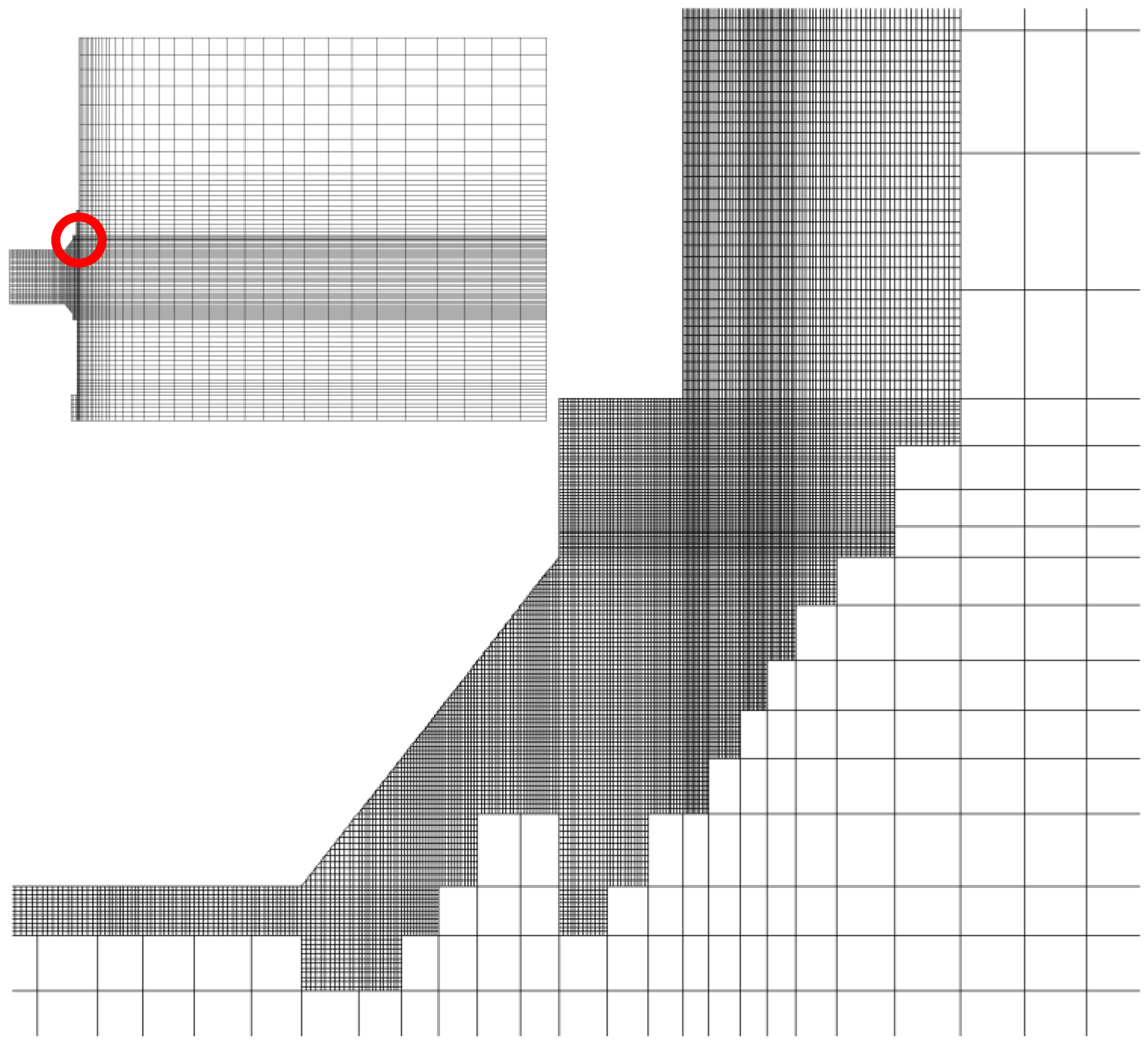
2. Grid Refinement for the Resolution of the Space-Charge Regions

Hall2De employs a magnetic-field-aligned mesh (MFAM) to solve electron fluid equations. The advantage of the MFAM approach is that it limits numerical diffusion in the electron momentum and energy equations that would otherwise be caused by the highly anisotropic transport coefficients in the parallel and perpendicular directions of the applied magnetic field. The equations of motion for the ions and neutrals can be solved on a rectilinear grid since these particles are not magnetized. As we mentioned in Section 1 the typical size of a grid element or “cell” is in the order of millimeters to tenths of millimeters. Resolving a sheath near the thruster walls requires higher resolution, even when the Debye length approaches that typical cell size. In Figure 2, we depict the refined grid in the neighborhood of the outer pole cover. Each coarse, rectilinear cell has been refined by a factor of 144 (with 12 partitions in each direction). Notice that this brings the typical cell size in the refined region to 5 × 10⁻⁵ m. Since the potential to electron temperature ratio, ϕ / T e , is large (~20 based on the plasma parameters in Figure 1) in the region highlighted in Figure 2, the sheath width can span 5 to 10 times the Debye length (~10−3 m) according to the solution to Poisson’s equation for a 1-D sheath [11]. Thus, the refined cell size chosen here provides enough resolution for the sheath in this region. On the other hand, even though we also refine the first cell adjacent to any wall boundary, the refined cell size in the interior of the channel is still at least an order of magnitude larger than the Debye length, which establishes the validity of the infinitesimal sheath approximation inside the channel.
In this implementation, grid refinement is performed at the time the code is initialized, and cells to be refined are flagged based on distance to the nearest wall. The level of refinement was chosen based on the Debye lengths computed in a previous simulation with only the coarse grid. We anticipate that the refinement algorithm may in the future be supplemented with an adaptive model that can refine regions in the computational domain based, for instance, on the magnitude of the gradients of the plasma properties and also provide refinement levels that vary based on the local Debye length at runtime. We limit the application of the refined grid only to the solution of Poisson’s equation (Section 3), thus limiting the increased computational cost associated with a larger number of cells to a single equation.

3. Algorithm for the Solution of Poisson’s Equation

In [23], we proposed a method that employed Poisson’s equation to complement the electron fluid equations for space charge regions. The same method is implemented here, with the distinction that it now makes use of the refined grid presented in Section 2. Without the appropriate mesh refinement, Poisson’s equation cannot resolve the potential gradient inside the sheath. At each computational time-step, the solution to the global governing equations of Hall2De [1] for the neutral particle motion, electron temperature, and plasma potential is advanced. The ion motion in the refined regions is determined using the PIC algorithm that will be described in Section 4. Poisson’s equation reads as follows:
2 ϕ s c = q e ε 0 i = 1 3 i n i n e
where ϕ s c is the space charge potential and n is the number density, with subscript i referring to the charge state (up to 3) of the ions and e to the electrons. In order to determine the electron number density in the space-charge region, it is necessary to make some assumptions about the energy distribution function of the electrons in the sheath. While kinetic theory descriptions of the electron distribution function in the sheath (e.g., [24,25]) are available in the literature, their implementation within our framework is not straight-forward. On the other hand, the classical assumption that the electrons follow Maxwellian distribution in an electron repelling sheath [10,11] is easy to implement and consistent with the use of the generalized form of Ohm’s law to compute the fluid potential in Hall2De [1]. Using this assumption yields the well-known Boltzmann relation:
n e = n e , 0 e x p ϕ s c ϕ 0 T e , 0
where ne,0, Te,0, and ϕ 0 are the values of the plasma density, electron temperature (in electronvolts), and potential, respectively, at the intersection of the edge of the sheath with a magnetic field line drawn from the point at which ne is being evaluated. Since the location of the sheath edge cannot be know a priori, we can take advantage of some of the known properties of magnetized electrons along magnetic field lines in Hall thruster discharges to determine the values of ne,0, Te,0, and ϕ 0 . Due to the higher (by approximately the Hall parameter squared) conductivity of the plasma in the direction parallel to the magnetic field, the electron temperature is approximately constant along magnetic field lines (see for example results in [1] and experimental evidence in [26,27]), and thus T e , 0 = T e . In addition, along magnetic field lines, and following the derivation in [1] where the inertia of the electrons is neglected, Ohm’s law may be expressed as the following:
/ / ϕ = η j e / / T e n e / / n e
with / / denoting the gradient along magnetic field lines, η the resistivity, and j e / / the electron current density along magnetic field lines. The resistive term can be neglected since the resistivity along magnetic field lines is very low; hence, the fluid approximation along magnetic field lines yields the Boltzmann relation for the electrons and the unknown values at the edge of the sheath can be related for convenience to the fluid values of the plasma density n e , F and fluid potential ϕ F in the location at which the space charge potential is being evaluated:
n e , F = n e , 0 e x p ϕ F ϕ 0 T e
with n e , F = i = 1 3 i n i as dictated by the quasi-neutrality assumption that is built into the fluid model. Combining the latter expression with Equation (2), the space charge density becomes the following
n e = n e , F e x p ϕ s c ϕ F T e
Numerical tests performed using this assumed relation for the electrons led to non-monotone values of the plasma potential in the sheath. For instance, negative values of the plasma potential were obtained when the walls were grounded. This occurred because Equation (5) does not account for the fact the plasma potential will ultimately deplete the sheath of all the electrons with lower energies than the wall potential, a limitation of assuming Maxwellian electrons. In this situation, the electrons adopt a truncated Boltzmann relation in which no electrons whose energy is lower than the minimum wall potential ϕ w at the boundaries of the computational domain are allowed [28]:
n e = n e , F e x p ϕ s c ϕ F T e e x p ϕ w ϕ F T e
Equation (1), using Equation (6) for the electron number density, is then solved at each cell center using an implicit-linearized approach. The fully implicit system of equations that determines the space-charge plasma potential at each cell k reads as follows:
k 2 ϕ s c t + Δ t = q e n e , F , k ε 0 1 e x p ϕ s c , k t + Δ t ϕ F , k T e , k + e x p ϕ w ϕ F , k T e , k
n e , F , k , ϕ F , k , and T e , k are known values evaluated at the center of cell k that come from the solution of the fluid equations in Hall2De [1]. These variables are updated by the fluid model in HallDe [1] at each time-step, but we have omitted the time superscript for them since they are not being updated when solving Equation (7). By the method of finite volumes, the discretized linear Laplacian operator k 2 can be written as follows:
k 2 f = 1 V k e = 1 n e d g , k f k e f k r k e r k 2 r k e r k · n ^ e A e
In Equation (8), Vk is the cell volume, nedg is the number of edges that form the contour of the cell, f k e is the value of the variable at the cell adjacent to k and separated by edge e, rk and rke are the location of the cell center for cell k and the adjacent cell ke, n ^ e is the normal vector of edge e pointing outwards from cell k, and Ae is the surface area of the edge. We also omitted in Equation (7) the temporal superscripts for the variables that are determined in the solution of the fluid equations. Equation (7) is non-linear and hence its solution requires an iterative process such as Newton–Raphson. A Taylor series linearization of the exponential term centered at the solution of the previous time-step, as follows:
e x p ϕ s c , k t + Δ t ϕ F , k T e , k e x p ϕ s c , k t ϕ F , k T e , k 1 + ϕ s c , k t + Δ t ϕ s c , k t T e , k
allows us to transform Equation (7) so it can be solved without iterations:
k 2 ϕ s c t + Δ t q e n e , F ε 0 e x p ϕ s c , k t ϕ F , k T e , k ϕ s c , k t + Δ t = q e n e , F ε 0 1 e x p ϕ s c , k t ϕ F , k T e , k 1 ϕ s c , k t T e , k + e x p ϕ w ϕ F , k T e , k
We note that Equation (10) is solved in the whole computational domain and not only in the refined regions. In locations where the Debye length is small and far from the boundaries, the solution of Equation (10) naturally converges to ϕ s c t + Δ t = ϕ F , k . Boundary conditions are imposed at the walls as follows. For electrically conducting boundaries, the potential of the conductor ϕ e j is specified as the value of a ghost cell adjacent to the boundary cell j. For insulating boundaries, the potential must satisfy j e = j i at the wall, where j i is the ion current density and is readily computed from the flux of ion particles leaving the computational domain at each boundary edge. The electron current density at the wall represented by the boundary edge of cell j can be approximated as follows:
j e , e k = q e n e , 0 q e T e , j 2 π m e e x p ϕ e j ϕ 0 T e , j = q e n e , F , j q e T e , j 2 π m e e x p ϕ e j ϕ F , j T e , j
where we have again used the Boltzmann relation (4) to relate the plasma properties at the edge of the sheath ( n e , 0 , ϕ 0 ) to those at the cell j adjacent to the edge ( n e , F , j , ϕ F , j ). Enforcing j e = j i while also accounting for secondary electron emission through the secondary electron yield Ye, ϕ e j can be determined from the following:
j i , e j = ( 1 Y e ( T e , j ) ) q e n e , F , j q e T e , j 2 π m e e x p ϕ e j ϕ F , j T e , j

4. Ion Motion in the Presence of Thick Sheaths

Ion motion is modeled with the PIC method. Since ions are unmagnetized, they follow the electric field that is computed from the space-charge potential field E s c = ϕ s c . We note here again that the solution for ϕ s c described in the previous section converges to the fluid-computed potential ϕ F in most of the computational domain and only diverges away from it near the walls when the Debye length is sufficiently large. Thus, the ion particle push at each time-step is performed using the following:
u t + t = u t + q i m i E s c t t
r t + t = r t + t 2 u t + t + u t
where u and r are the velocity and position of each ion macro-particle, respectively, and Esc is computed using bilinear interpolation from the values stored at the vertices of the grid to the particle location inside a cell. The ion charge and mass are q i and m i , respectively. The time-step for the particle push is limited by the Courant condition:
t m a x = m i n p V k , p 1 / 3 u p
where p is an index for all the particles in the computational domain, u p is the particle velocity, and Vk,p is the volume of the cell k where p is located at a given time-step. t m a x is therefore much smaller in a simulation with refined regions than in a simulation that only uses the coarse grid. To avoid the excessive computational cost of smaller time-steps, particles in the refined regions are flagged, and thus two Courant conditions are computed, t m a x , c o a r s e and t m a x , r e f i n e d . Then, we compute the ratio:
R t = c e i l i n g t m a x , c o a r s e t m a x , r e f i n e d
where R t is the nearest integer larger than the ratio of the two Courant conditions. At each global time-step (that is, time-steps for particles in the coarse grid), particles in the refined grid undergo R t time-steps with t r e f i n e d = t c o a r s e r t . Particles that were in the coarse region and transitioned to the refined region during any given time-step are flagged and returned to their starting position and velocity at the beginning of the time-step. Then, they are pushed again using the time-stepping scheme of the refined region. Since the refined regions are relatively small and close to the boundaries, the fraction of particles that are subject to the smaller time-steps is rather small, approximately 4 to 5% of the total number of particles present at a given time-step in a typical simulation.

5. Results

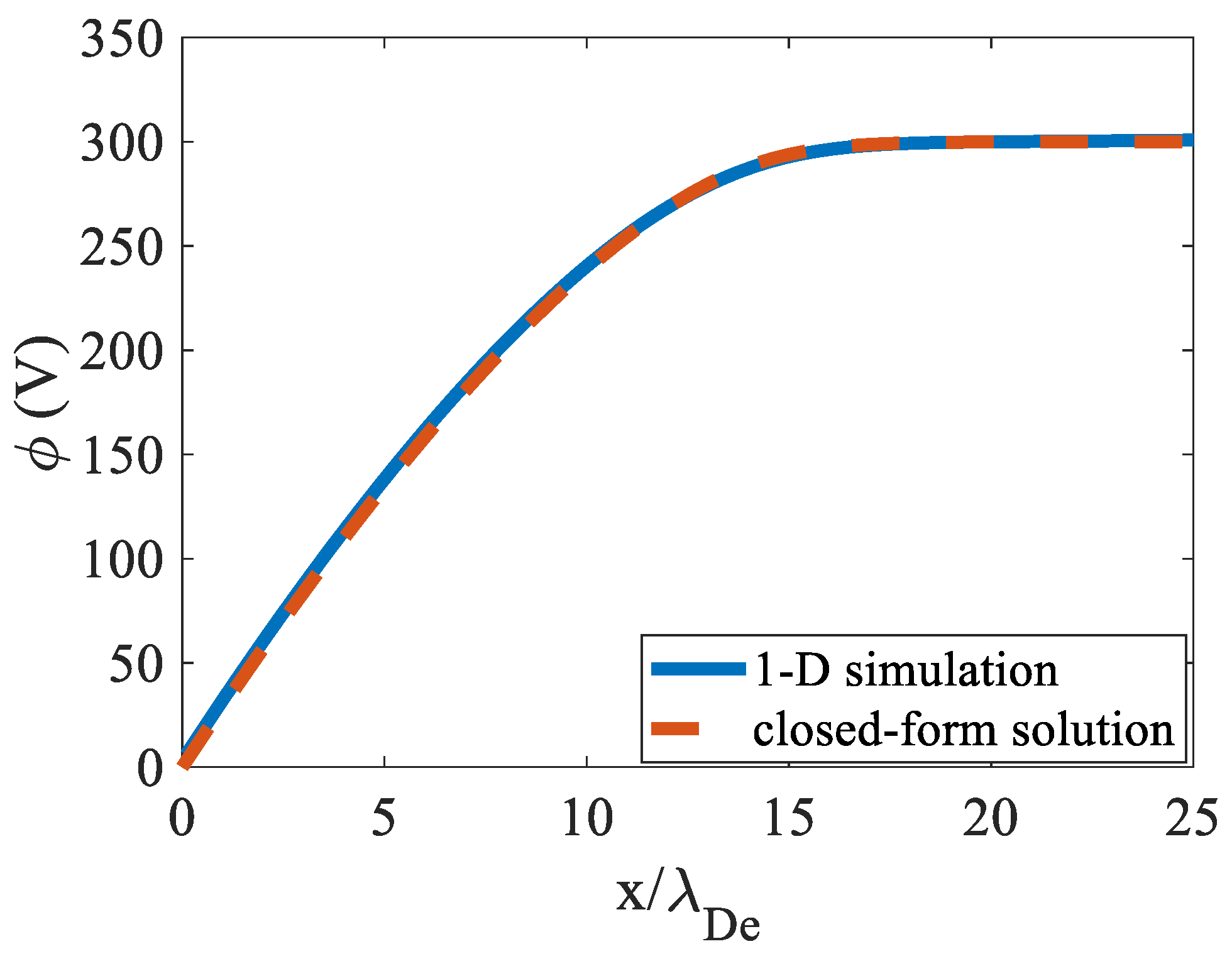
5.1. Verification in One Dimension (1-D)

We first tested the model described in the previous sections using a simplified 1-D simulation. We constructed a computational domain with an electrically conducting wall grounded to 0 V on the left side and an inflow of ions on the right side. The electron fluid equations were not solved. Instead, the values of the electron temperature (Te = 5 eV) and plasma potential ( ϕ F = 300 V) at the edge of the sheath were specified as inputs. Singly-charged xenon ions were injected into the computational domain from the right with velocity ui = 3820 m/s and at a rate that produced a plasma density at the edge of the sheath of ne = 3 × 10¹⁶ m−3, which yields λDe = 9.6 × 10⁻⁵ m. The space-charge potential at the right boundary is set to 300 V. Ions that reach the left boundary are removed from the simulation. In this setup, ions are accelerated by the space-charge electric field as derived from Equation (10). The computational domain spanned 25λDe and had 120 cells, so each cell had a length of 2 × 10⁻⁵ m. The average number of PIC particles per cell was 100. Steady state was reached in a time ~ 20 λ D e 2 q e ϕ F m i , where mi is the ion mass. In Figure 3, the steady-state space-charge potential (Equation (7)) from the 1-D numerical test is compared to the solution of the ordinary differential equation for a one-dimensional Langmuir sheath [11]:
d χ d ξ = 4 M 0 1 + ξ M 0 1 + 2 ( e x p ( ξ ) 1 )
with χ = Δ ϕ s h ϕ T e , ξ = x λ D e , M 0 = m i u i 2 2 q e T e , and x denoting the axial dimension. Δ ϕ s h is the potential drop in the sheath (300 V in this case). We solved Equation (17) numerically using a fourth order Runge–Kutta scheme. As shown in Figure 3, the numerical and closed-form solutions agree remarkably well, with | | ϕ s c ϕ t h | | / | | ϕ t h | | = 0.017, where the subscripts “sc” and “th” refer to the numerical and closed-form potentials, respectively.

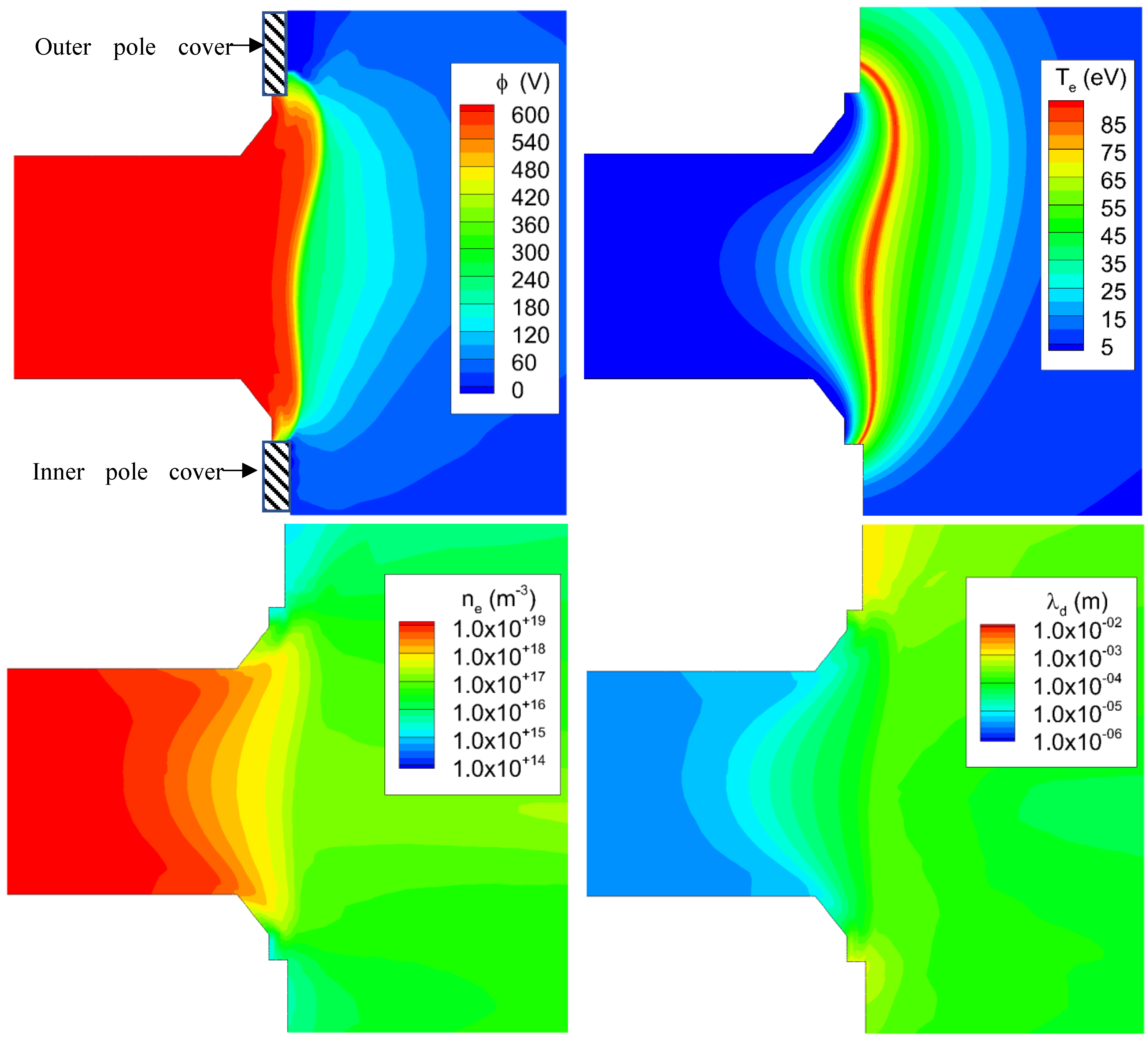
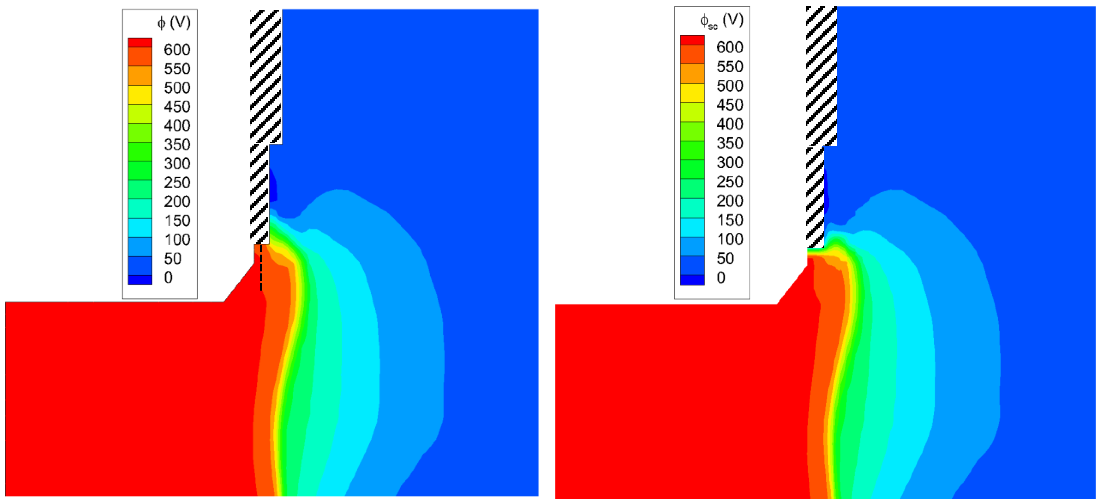
5.2. 2D Numerical Simulations with the Axial–Radial Code Hall2De

In this section, we report the results of 2D axisymmetric Hall thruster simulations where the space-charge model has been fully integrated in Hall2De. The simulations are of a 12.5-kW magnetically shielded thruster operating with discharge current and voltage of 20.8 A and 600 V, respectively. Further details on Hall2De simulations, such as a description of the computational domain, boundary conditions, and physics models for neutrals, ions, and electrons, can be found in [1,17]. Figure 4 depicts the simulation results near the outer pole cover, with the fluid plasma potential and infinitesimal-sheath boundary conditions on the left and the space-charge potential on the right. As expected, most of the differences between the two contour plots are found around the pole cover surface, which is biased to 0 V. Thus, a finite sheath develops that is especially visible near the lateral surface at the inner diameter of the cover, that is, the part of the cover facing the acceleration channel. In this region, the potential transitions from almost 600 V to 0 V at the walls, with the Debye length being approximately 10−4 m. Here, the infinitesimal-sheath approximation is clearly not accurate and could lead to errors in erosion predictions as we will discuss later. As we move away from the lateral surface towards the outer diameter of the cover, the space charge and fluid solutions progressively converge as the fluid potential becomes closer to the wall potential of 0 V. Because the new space-charge algorithm resolves the spatial extent of the sheath from the boundaries, we shall also use the term “finite-sheath solution” hereinafter when discussing the solution from this new algorithm. We also note that there are no regions in which the fluid potential 0 = ϕ w > ϕ is less than zero. Thus, the truncation term in Equation (6), which was implemented due to the limitations of a Maxwellian description of the electrons, has a negligible effect in this simulation.
Similar conclusions can be drawn from the comparisons between the fluid and space-charge potentials at the inner pole (Figure 5). Here, the computed plasma potential from the hydrodynamic solution with infinitesimal-sheath boundary conditions at the outer diameter of the pole cover, the side facing the acceleration channel, is lower than that at the outer pole cover. Since the potential drop in the sheath is lower, the differences between the finite-sheath and infinite-sheath models are not as acute as in the vicinity of the inner diameter of the outer pole cover.
Around the dielectric channel walls of the thruster, the infinitesimal-sheath and space-charge solutions are the same. Since the thruster is magnetically shielded, the temperatures at the wall are in the order of 2–3 eV, leading to very small potential gradients in the sheath from Equation (12). Second, the Debye length in the channel is very small (Figure 1) and thus the refined grid cannot resolve the sheath. Thus, the infinitesimal sheath assumption in the channel is correct and the space-charge model does not improve the overall solution of the potential near the dielectric walls.
In Figure 6, we compare the space-charge solution along a radial cross-section that intersects the mid-point of the lateral surface at the inner diameter of the outer pole cover (see dashed black line in Figure 4) with the closed-form solution given by Equation (17). Parameters for the closed-form solution were obtained directly from the Hall2De solution at the edge of the sheath (~2.1 mm from the wall in Figure 4) and are ne = 5.68 × 10¹⁶, Te = 2.19 eV, φ = 598 V, ui = 4500 m/s, and λDe = 4.67 × 10⁻⁵ m. As in the 1-D test case, the two solutions agree remarkably well.
We conclude this section with a discussion on the effects the space-charge potential on erosion predictions for the pole covers. Figure 7 shows the computed erosion rates on the graphite outer pole cover for the 12.5-kW magnetically shielded Hall thruster at 600 V and 20.8 A. The normalized coordinate employed in the x-axis refers to the location along a line that follows the contour of the outer pole cover at constant azimuth angle, with 0 and 1 being the locations nearest and furthest from the acceleration channel, respectively. The model for computing ion sputtering of these graphite surfaces has been described in [29]. As expected by the visual examination of the finite- and infinitesimal-sheath solutions for the potential in Figure 4, the largest differences in predicted erosion occur at the lateral surface of the inner diameter (region 1 in Figure 7), where the finite-sheath model predicts erosion rates that are larger by an order of magnitude. The finite-sheath model also predicts larger erosion rates at the mid-point of the pole cover (region 3). To further elucidate these results, we depict in Figure 8 the current density and average energy of the ions sputtering the cover. At the inner diameter, the average energy of the ions is very similar in both models. This is expected as the energy of the ions is dominated by the drop in potential across the sheath. In the finite-sheath model, the ions gain energy as they traverse the sheath that is resolved within the computational domain, while in the infinitesimal-sheath model, the energy gained by the ions in the sheath is added after the particle exits the computational domain. However, in both cases, the energy gained by the ions is approximately the same (~600 V). On the other hand, the flux of ions towards the inner diameter of the pole is larger by an order of magnitude in the finite-sheath model, accounting for the difference in erosion rates between the two models. The finite-sheath model moves the edge of the sheath from the boundary of the computational domain to approximately 2 mm away from it (see Figure 6). As such, ions as far as 2 mm away are subject to a plasma potential that attracts them towards the lateral surface of the cover. In the infinitesimal-sheath model, there is no plasma potential gradient that extends into the computational domain and, consequently, fewer ions move towards the cover surface. The difference in erosion at the mid-point step (region 3) is due to a combination of the larger current density and energy of the ions sputtering in this region. As shown in Figure 4, the potential contours in the finite-sheath model are different from those of the infinitesimal-sheath model in the vicinity of the inner diameter in region 2. The finite-sheath solution leads to potential contours that are approximately parallel to the step surface, while the contours in the infinitesimal-sheath solution are at an angle. This results in more high-energy ions moving radially towards the mid-point step in the finite-sheath solution.

6. Conclusions

A computational capability has been developed for Hall thrusters that allows for the self-consistent resolution of thick-sheath regions within the framework of global 2D multifluid-PIC numerical simulations. The space charge near thruster boundaries that are immersed in the low-density regions of the discharge can produce regions where the sheath thickness is much larger than the local grid resolution permitted by the global simulation. Such regions require the direct solution of Poisson’s equation, which is normally not solved in simulations where the electrons are modeled as a fluid. The resolution of the sheath in these regions is critical in the assessment of Hall thruster life-limiting processes like ion sputtering.
The space-charge algorithm developed here has been verified and then integrated into a global hybrid simulation of Hall thrusters in 2D axial–radial domain. The computational approach consists of (1) local grid refinement, (2) solution of Poisson’s equation in the refined regions, and (3) solution of the equations for the ion motion using the PIC method with special time-stepping in the refined regions. The numerical solution has been verified, first in a separate one-dimensional simulation and then in larger-scale 2D axisymmetric simulations. In the 2D simulations, the space-charge solver was integrated self-consistently in the Hall2De code, a well-established simulation capability for Hall thrusters. With this capability in the Hall2De code, we are now able to resolve sheaths around critical thruster surfaces, like pole covers in magnetically shielded Hall thrusters, which significantly improves the accuracy of thruster lifetime predictions.

Author Contributions

Conceptualization, A.L.O. and I.G.M.; methodology, A.L.O.; validation, A.L.O.; formal analysis, A.L.O.; investigation, A.L.O. and I.G.M.; writing—original draft preparation, A.L.O.; writing—review and editing, I.G.M.; All authors have read and agreed to the published version of the manuscript.

Funding

This research received no external funding.

Institutional Review Board Statement

Not applicable.

Informed Consent Statement

Not applicable.

Data Availability Statement

Data supporting reported results may be provided by the authors upon request.

Acknowledgments

The support of the joint NASA Glenn Research Center (GRC) and JPL development of the Advanced Electric Propulsion System by NASA’s Space Technology Mission Directorate through the Solar Electric Propulsion Technology Demonstration Mission project is gratefully acknowledged. The research described in this paper was carried out at the Jet Propulsion Laboratory, California Institute of Technology, under a contract with the National Aeronautics and Space Administration (No. 80NM0018D0004). © 2023. California Institute of Technology. Government sponsorship acknowledged.

Conflicts of Interest

The authors declare no conflict of interest.

References

  1. Mikellides, I.G.; Katz, I. Numerical Simulations of Hall-effect Plasma Accelerators on a Magnetic-Field-Aligned Mesh. Phys. Rev. E 2012, 86, 046703. [Google Scholar] [CrossRef]
  2. Fife, J.M. Hybrid-PIC Modeling and Electrostatic Probe Survey of Hall Thrusters. Ph.D. Thesis, Massachusetts Institute of Technology, Cambridge, MA, USA, 1998. [Google Scholar]
  3. Parra, I.; Ahedo, E.; Fife, J.M.; Martinez-Sanchez, M. A Two-Dimensional Hybrid Model of the Hall Thruster Discharge. J. Appl. Phys. 2006, 100, 023304. [Google Scholar] [CrossRef]
  4. Pereles-Diaz, J.; Dominguez-Vazquez, A.; Fajardo, P.; Ahedo, E.; Faraji, F.; Reza, M.; Andreussi, T. Hybrid plasma simulations of a magnetically shielded Hall thruster. J. Appl. Phys. 2022, 131, 103302. [Google Scholar] [CrossRef]
  5. Scharfe, M.K.; Gascon, N.; Cappelli, M.A.; Fernandez, E. Comparison of Hybrid Hall Thruster Model to Experimental Measurements. Phys. Plasmas 2006, 13, 083505. [Google Scholar] [CrossRef]
  6. Sommier, E.; Scharfe, M.K.; Gascon, N.; Cappelli, M.A.; Fernandez, E. Simulating Plasma-Induced Hall Thruster Wall Erosion with a Two-Dimensional Hybrid Model. IEEE Trans. Plasma Sci. 2007, 35, 1379–1387. [Google Scholar] [CrossRef]
  7. Hagelaar, G.J.M.; Bareilles, J.; Garrigues, L.; Boeuf, J.P. Two-Dimensional Model of a Stationary Plasma Thruster. J. Appl. Phys. 2002, 91, 5592–5598. [Google Scholar] [CrossRef]
  8. Garrigues, L.; Hagelaar, G.J.M.; Boniface, C.; Boeuf, J.P. Anomalous Conductivity and Secondary Electron Emission in Hall Effect Thrusters. J. Appl. Phys. 2006, 100, 123301. [Google Scholar] [CrossRef]
  9. Hagelaar, G.J.M. Modelling Electron Transport in Magnetized Low-Temperature Discharge Plasmas. Plasma Sources Sci. Technol. 2007, 16, S57–S66. [Google Scholar] [CrossRef]
  10. Hobbs, G.D.; Wesson, J.A. Heat Flow through a Langmuir sheath in the Presence of Electron Emission. Plasma Phys. 1967, 9, 85–87. [Google Scholar] [CrossRef]
  11. Riemann, K.U. The Bohm Criterion and Sheath Formation. J. Phys. D Appl. Phys. 1991, 24, 493–518. [Google Scholar] [CrossRef]
  12. Mikellides, I.G.; Katz, I.; Hofer, R.R.; Goebel, D.M. Magnetic Shielding of Walls from the Unmagnetized Ion Beam in a Hall Thruster. Appl. Phys. Lett. 2013, 102, 023509. [Google Scholar] [CrossRef]
  13. Mikellides, I.G.; Katz, I.; Hofer, R.R.; Goebel, D.M.; de Grys, K.; Mathers, A. Magnetic Shielding of the Channel Walls in a Hall Plasma Accelerator. Phys. Plasmas 2011, 18, 033501. [Google Scholar] [CrossRef]
  14. Sekerak, M.J.; Hofer, R.R.; Polk, J.E.; Jorns, B.A.; Mikellides, I.G. Wear Testing of a Magnetically Shielded Hall Thruster at 2000-s Specific Impulse. In Proceedings of the IEPC 2015-155, 34th International Electric Propulsion Conference, Kobe, Japan, 4–10 July 2015. [Google Scholar]
  15. Lopez Ortega, A.; Mikellides, I.G.; Sekerak, M.J.; Jorns, B.A. Plasma Simulations in 2-D (r-z) Geometry for the Assessment of Pole Erosion in a Magnetically Shielded Hall Thruster. J. Appl. Phys. 2019, 125, 033302. [Google Scholar] [CrossRef]
  16. Lopez Ortega, A.; Mikellides, I.G.; Chaplin, V.H.; Huang, W.; Frieman, J.D. Anomalous Ion Heating and Pole Erosion in the 12.5-kWHall Effect Rocket with Magnetic Shielding (HERMeS). In Proceedings of the AIAA 2020-3620, AIAA Propulsion and Energy, Virtual Conference, 24–26 August 2020. [Google Scholar]
  17. Lopez Ortega, A.; Mikellides, I.G. Validation of Hall2De Simulations with Anomalous Ion Heating in the Pole Region of a Magnetically Shielded Hall Thruster. In Proceedings of the IEPC 2022-299, 37th International Electric Propulsion Conference, Boston, MA, USA, 19–23 June 2022. [Google Scholar]
  18. Adam, J.C.; Heron, A.; Laval, G. Study of Stationary Plasma Thrusters Using Two-Dimensional Fully Kinetic Simulations. Phys. Plasmas 2004, 11, 295–305. [Google Scholar] [CrossRef]
  19. Szabo, J.J. Fully Kinetic Numerical Modeling of a Plasma Thruster. Ph.D. Thesis, Massachusetts Institute of Technology, Cambridge, MA, USA, 2001. [Google Scholar]
  20. Cho, S.; Komurasaki, K.; Arakawa, Y. Kinetic Particle Simulation of Discharge and Wall Erosion of a Hall Thruster. Phys. Plasmas 2013, 20, 063501. [Google Scholar] [CrossRef]
  21. Sahu, R.; Mansour, A.R.; Hara, K. Full Fluid Moment Model for Low Temperature Magnetized Plasmas. Phys. Plasmas 2020, 27, 113505. [Google Scholar] [CrossRef]
  22. Boccelli, S.; McDonald, J.G.; Magin, T.E. 14-Moment Maximum-Entropy Modeling of Collisionless Ions for Hall Thruster Discharges. Phys. Plasmas 2022, 29, 083903. [Google Scholar] [CrossRef]
  23. Lopez Ortega, A.; Mikellides, I.G.; Katz, I. Hall2De Numerical Simulations for the Assessment of Pole Erosion in a Magnetically Shielded Hall Thruster. In Proceedings of the IEPC 2015-249, 34th International Electric Propulsion Conference, Kobe, Japan, 4–10 July 2015. [Google Scholar]
  24. Ordonez, C.A. Fully Kinetic Plasma-Sheath Theory for a Cold-Electron Emitting Surface. Phys. Fluids B Plasma Phys. 1992, 4, 778–783. [Google Scholar] [CrossRef]
  25. Sheehan, J.P.; Hershkowitz; Kaganovich, I.D.; Wang, H.; Raitses, Y.; Sydorenko, D. Kinetic Theory of Plasma Sheaths Surrounding Electron-Emitting Surfaces. Phys. Rev. Lett. 2013, 111, 075002. [Google Scholar] [CrossRef]
  26. Reid, B.; Gallimore, A. Langmuir Probe Measurements in the Discharge Channel of a 6-kW Hall Thruster. In Proceedings of the AIAA 2008-4920, 44th AIAA/ASME/SAE/ASEE Joint Propulsion Conference, Hartford, CT, USA, 21–23 July 2008. [Google Scholar]
  27. Mikellides, I.G.; Katz, I.; Hofer, R.R.; Goebel, D.M. Magnetic Shielding of a Laboratory Hall Thruster. I. Theory and Validation. J. Appl. Phys. 2014, 115, 043303. [Google Scholar] [CrossRef]
  28. Hara, K.; Hanquist, K. Test Cases for Grid-Based Direct Kinetic Modeling of Plasma Flows. Plasma Sources Sci. Technol. 2018, 27, 065004. [Google Scholar] [CrossRef]
  29. Yim, J.T. A Survey of Xenon Ion Sputter Yield Data and Fits Relevant to Electric Propulsion Spacecraft Integration. In Proceedings of the IEPC 2017-060, 35th International Electric Propulsion Conference, Atlanta, GA, USA, 8–12 September 2017. [Google Scholar]
Figure 1. Plasma properties (plasma potential, electron temperature, plasma density, Debye length) in the acceleration channel and region near the pole covers of a 12.5-kW magnetically shielded thruster operating at 600 V and 20.8 A.
Plasma 06 00038 g001
Figure 2. The refined grid in the vicinity of the channel exit and outer pole cover. Red circle highlights this region with respect to the complete grid.
Plasma 06 00038 g002
Figure 3. Comparison between the space-charge potential determined numerically using a 1-D computational domain with a conducting boundary and the closed-form solution, Equation (17), for the same setup.
Plasma 06 00038 g003
Figure 4. Computed potential contours around the outer pole cover from a Hall2De simulation of a magnetically shielded thruster at 600 V and 20.8 A, with (left) infinitesimal-sheath solution at the boundaries, (right) space-charge solution with grid refinement around the boundaries.
Plasma 06 00038 g004
Figure 5. Plasma potential contours around the inner pole cover in a Hall2De simulation for magnetically shielded thruster at 600 V and 20.8 A, with (left) no space-charge solution, (right) space-charge solution.
Plasma 06 00038 g005
Figure 6. Comparison between the closed-form solution for the space-charge potential (Equation (17)) and the computed values from the Hall2De simulation along a radial cross-section that intersects the mid-point of the lateral surface of the outer pole cover.
Plasma 06 00038 g006
Figure 7. Comparison of erosion rates along the outer pole cover from 2D simulations with the finite-sheath and infinitesimal-sheath models. Dashed-dotted lines denote transitions in orientation of the pole cover surfaces (refer to numbers 1–4 in contour plot).
Plasma 06 00038 g007
Figure 8. Comparison of the ion current density (left) and average ion energy (right) along the outer pole cover from simulations with the finite- and infinitesimal-sheath models. Dashed-dotted lines denote transitions in orientation of the pole cover surfaces (refer to numbers 1–4 in Figure 7).
Plasma 06 00038 g008
Disclaimer/Publisher’s Note: The statements, opinions and data contained in all publications are solely those of the individual author(s) and contributor(s) and not of MDPI and/or the editor(s). MDPI and/or the editor(s) disclaim responsibility for any injury to people or property resulting from any ideas, methods, instructions or products referred to in the content.

