Review

Physical Processes That Occur in Self-Organized Tokamak Plasma

by
Ksenia A. Razumova
and
Sergey E. Lysenko
*
National Research Center ‘Kurchatov Institute’, 123182 Moscow, Russia
*
Author to whom correspondence should be addressed.
Plasma 2023, 6(3), 408-418; https://doi.org/10.3390/plasma6030028
Submission received: 10 May 2023 / Revised: 25 June 2023 / Accepted: 5 July 2023 / Published: 12 July 2023
(This article belongs to the Special Issue Feature Papers in Plasma Sciences 2023)

Abstract

:
Processes associated with plasma self-organization in tokamaks are presented in the possible logical sequence. The resulting picture of physical processes in self-organized plasmas is predicted based on the nonrequiibrium thermodynamic approach, which uses the Smoluchowski-type equation for the energy balance. The self-organization of magnetized plasma leads to the formation of the universal MHD structure, where the normalized pressure profiles are similar. Finally, experimental confirmation of the proposed physical picture in magnetic fusion facilities is given.

1. Introduction

At the very beginning of fusion research, scientists hoped that it would be possible to create conditions in which the plasma would be stable and have the classical confinement of energy and particles. However, in the early 1960s, they understood that this was unattainable. Plasma is always unstable; moreover, it is always turbulent. At that time, laws governed by turbulent plasma were unknown, and for several decades, the behavior of plasma was described using the classical collision theory, but with anomalously increased particle and energy transport coefficients. At that time, a reasonable description of experiments was not obtained. The powerful gyrokinetic codes then were not very successful. They were able to predict the formation of dominant modes in a turbulent plasma background. However, so far, it has not been possible to create a general coherent physical picture. Besides the fact that instabilities are strongly nonlinear, they also nonlinearly interact with each other. Instead of the physical logic, so-called “modes of operation” and the statistically defined scaling laws for the dependence of the energy confinement time on the plasma parameters and conditions of transition from one operational mode to another were introduced. The physical meaning of these processes was lost because we did not take into account one very important factor.
Since the middle of the last century, a new approach has been developed in physics to consider “the complex systems”, i.e., the strongly nonlinear open systems with many degrees of freedom. An open system is a system that has the ability to exchange energy and particles with the external environment. It was shown [1] that in such systems, described using a new statistical approach called nonequilibrium thermodynamics, the entropy may not increase, leading the system to chaos, but establishes the regime, where the free energy in the system is minimal. By analogy with conventional thermodynamics, it is described using the equation:
F = E S · θ ,
where F is the free energy, in this case, the energy of the turbulent background in the plasma (instead of the kinetic energy of particles in conventional thermodynamics); E is the total energy of the system; S is the entropy; and θ is the equivalent of thermodynamic temperature. J.B. Taylor called it ‘magnetic temperature’ [2]. Such a system exists stably and stationary under external influences. The only requirement is always the minimization of free energy. If the system has some subsystems or internal structures, then these subsystems must also have a minimum of F. Then, this requirement will be fulfilled in the entire system. Thanks to this law, discovered by I. Prigogine (Nobel Prize in 1977), it was possible to explain a set of phenomena in various fields of science, including astrophysics, biology, chemistry, atmospheric physics, sociology, etc.

2. Self-Organization in Tokamak Plasma

Plasma is a typical example of a complex system and, accordingly, it is always self-organized when time is greater than the time of turbulent relaxation. This process is inevitable as the equilibrium is established. As was shown in [3], as a result of this process in a magnetized plasma, the self-consistent normalized pressure profile is formed, which is the same for all devices, where the plasma is frozen in a longitudinal magnetic field [4,5,6,7,8,9]. We normalized the pressure profile to its central value: pN() = p()/p(0), and normalized the radial coordinate to the radius of any magnetic surface outside the zone, where the plasma current is flowing (e.g., to the surface with q = 5): = r/(IR/kB)1/2, where k is the plasma cross-section elongation, B is the toroidal magnetic field, I is the plasma current, and R is the major radius of the torus.
We cannot describe the processes in a turbulent background that lead to the minimization of F since there are many interacting fluctuations and all processes are very non-linear. However, we know that each instability, while developing, must stabilize itself since it depletes the source (e.g., smooth the gradient) that feeds it. Interacting instabilities can both stabilize and excite each other, but, seemingly, the general trend towards a decrease in activity should be held out.
Under these conditions, the energy balance equation must maintain a self-consistent pressure profile, so, the usual Fick-type flux-gradient equation is invalid. K.S. Dyabilin [3] proposed the use of the Smoluchowski-type equation:
p t = 1 ρ ρ ρ Γ + Q .
Γ = κ p p p p c p c .  
Here p and pc are real and self-consistent pressures, Q is the source of heating and cooling, is the radial coordinate, Γ is the flux, and κ is the thermal conductivity.
Instead of proportionality between the flux and the gradient, we see that the flux depends on the difference between the logarithmic gradients of p and pc. The real pressure profile always differs from pc. Below we estimate this difference.
As we can see, Equation (3) contains only the thermal conductivity coefficient κ, and there is no diffusion coefficient. This is understandable since turbulent plasma is continuously being mixed with a turbulent relaxation time that slightly exceeds the inertial one, and the heat and particle fluxes cannot be separated. According to [3], the thermal conductivity coefficient κ = θχ, where θp(0)β(0)/qedge, β(0) = 8πp(0)/B2 is the pressure normalized on the pressure of the toroidal magnetic field B, χ is the dissipation factor, and q is the safety factor. Denote Γ0 as the radial heat flux for the unperturbed self-organized regime. This flux determines the best possible energy confinement under the given external conditions that is for a given θ. In contrast with the empirical statistical scaling, θ is independent of the density [10], but certainly θ depends on q, and, therefore, on the vertical elongation k and the aspect ratio R/a. The modern spherical tokamaks ST40 [11] and Globus-M2 [12] may allow one to check the dependence θ(q) with a wide variation of k and R/a.
Let χ0 be the dissipation coefficient for this case. Since the pressure profile is independent of either the power deposited in the plasma or the geometry, χ0 should also have the same properties. Such an unperturbed regime can be realized with ohmic heating (OH) if the heat flux from electrons to ions is negligibly small. Under conditions of self-organization, the input OH power profile can be adjusted to match the self-consistent pressure profile. The OH power dependence on the temperature is P r T e 3 / 2 . If it is deposited in accordance with the pressure profile, P r p r n e T e , then T e 3 / 2 n e T e . In this case, the electron temperature profile, proportional to the square of the electron density profile T e n e 2 will be realized. We do not yet know the structure of the Γ0 flux, but we suppose that this flow is formed on fluctuations of the bootstrap current, since pressure profile distortions should excite pressure fluctuations in a turbulent background, inevitably associated with fluctuations of the bootstrap current.
If the external impacts try to distort the pressure profile, then the additional free energy should appear, that is, the activity of the turbulent background should rise, but the background should minimize it. A new configuration must be created with the favorable energy distribution. Such requirements for the MHD system are implied in the MHD island with a current that maintains a self-consistent additional pressure profile inside the island with the dissipation coefficient χ0. The free energy F in such a subsystem is always minimal, and the value of the accumulated energy depends on the poloidal number of the island, m. Thus, the pressure profile distortions should always be associated with the formation of the island with the appropriate scale.

2.1. Neoclassical Tearing Modes

From the point of view of plasma self-organization, if the current in the island begins to decay, then F increases. The flattening of the current profile in the island leads to the change of the pressure profile and violates the condition F = Fmin. This activates the turbulent background, which maintains the current and pressure profiles in the island. Thus, the neoclassical tearing mode (NTM), the mode with flattened pressure profile inside the island, cannot exist at times longer than the time of turbulent relaxation because this contradicts the condition F = Fmin. Figure 1 shows a sketch explaining the formation of the total pressure profile in the presence of the island. We see that in some cases, the total profile flattens with a bell-shaped profile inside the island.

2.2. The Perturbed Flux Γ1

If the pressure profile distortions are distributed along the radius, then a chain of islands with number m should appear, corresponding to the intensity of impact on the given radius. Such islands can interact with each other if their edges are overlapped, as shown in Figure 2. The magnetic surfaces in such zones are destroyed, and the radial heat flux should occur. It reduces the impacts that deform the pressure profile: the larger the impacts, the lower the poloidal number m. We denote this flux as Γ1, and its dissipative coefficient as χ1. It is clear that χ1 should be the higher; the higher the disturbance and Γ1. Therefore Equation (3) to become very complicated, since κ = θ χ 0 + χ 1 Γ 1 .
The flux Γ1 appears when the profile of the additional heating power is inconsistent with the self-organized pressure profile. The buildup of the turbulent background can drastically enlarge the thermal conductivity. If the flux freely reaches the plasma edge, reducing the pressure gradient there, it may carry out the whole input power for a short time due to a high-thermal conductivity [10].
However, if Γ1 is interrupted somewhere, in order to keep unperturbed plasma at the edge, then the self-organized pressure profile will be constructed in accordance with the gradient at the edge, and the confinement again would correspond to χ0. A characteristic feature of the self-organized plasma is that its confinement is determined only by its edge, regardless of the processes inside the system. This is because the free energy of the entire system as a whole should be minimized.
On its path along the radius, the flux Γ1 may encounter the gap between rational surfaces. This gap inevitably arises at sufficiently low numbers m, (the width of gap Δ∝q2/(mdq/dr)). Then, the connection between the islands in the flux Γ1 can break, because the island edges are not superposed, and a so-called internal transport barrier is formed. The break in the Γ1 flux leads to an increase in the pressure gradient in the barrier zone until the continuity of the heat flux is restored due to the flux Γ0. In this case, the pressure profile must be strongly distorted, and, in accordance with the above, the turbulent background must minimize the free energy by forming the island on the rational surface of the barrier.
An island with a given number m has a certain energy store. With the large Γ1 flux, the island should be rebuilt, and its number decreases. When the size of the island on the magnetic surface with given q (for example, q = 3/2, m = 3) reaches its maximum, the buildup of the turbulent background can no longer form a new energetically more favorable MHD configuration because it is simply absent. This should lead to the release of the corresponding portion of free energy in the form of an avalanche flow. Usually, this process is referred to as “the internal disruption”.
If, in these conditions, we increase Γ1, therefore, increasing the energy deposition at the plasma center, we only intensify this destructive process, which limits β value for a given q(r) profile. To increase the energy store, it is necessary to interrupt the Γ1 flux not by the single, but by several barriers.
Thus, the total radial heat flux consists of two parts: a permanently existing small flux of self-organized plasma Γ0 and the arbitrarily large perturbed flux Γ1. In addition, there is always a neoclassical flux, which is negligible for conventional tokamaks if the frequency collision for ions is not low enough to have the high ’banana’ heat conductivity conditions. Moreover, it may be significant for spherical tokamaks.
For a very low-collision frequency, when ions are energetically separated from electrons, the ion neoclassical transport is greater than the turbulent one Γneo > Γ0 + Γ1.

2.3. Sizes of the Islands Carrying the Flux Γ1

We do not yet know the quantitative relationship between the flux Γ1 and the poloidal number of the island, but we can estimate the minimal size of the island. Since the island is the result of a generalization of turbulent background fluctuations, its size must be greater than the maximal size of fluctuations. We do not know the structure of turbulence very well, and it can be changed in different operating regimes of the tokamak, but, apparently, the maximal size of fluctuation is determined using the thermal ion Larmor radius L. Typically, in tokamaks such as TEXTOR and T-10, it is about 2 mm. The ratio of two islands’ sizes located at the given radius depends on the inverse of their m numbers: s1/s2 = m2/m1. Taking the TEXTOR data for m/n = 2/1 island with a size of 7–8 cm [13], we obtain a rough estimate that for the smallest island, m = 20–25. This means that smaller impacts on the profile do not excite Γ1, but they remain as slight distortions of the pressure profile at the same χ0. The size of turbulent fluctuations determines the stiffness of the pressure profile.

3. Comparison of Our Conceptions with Experiment

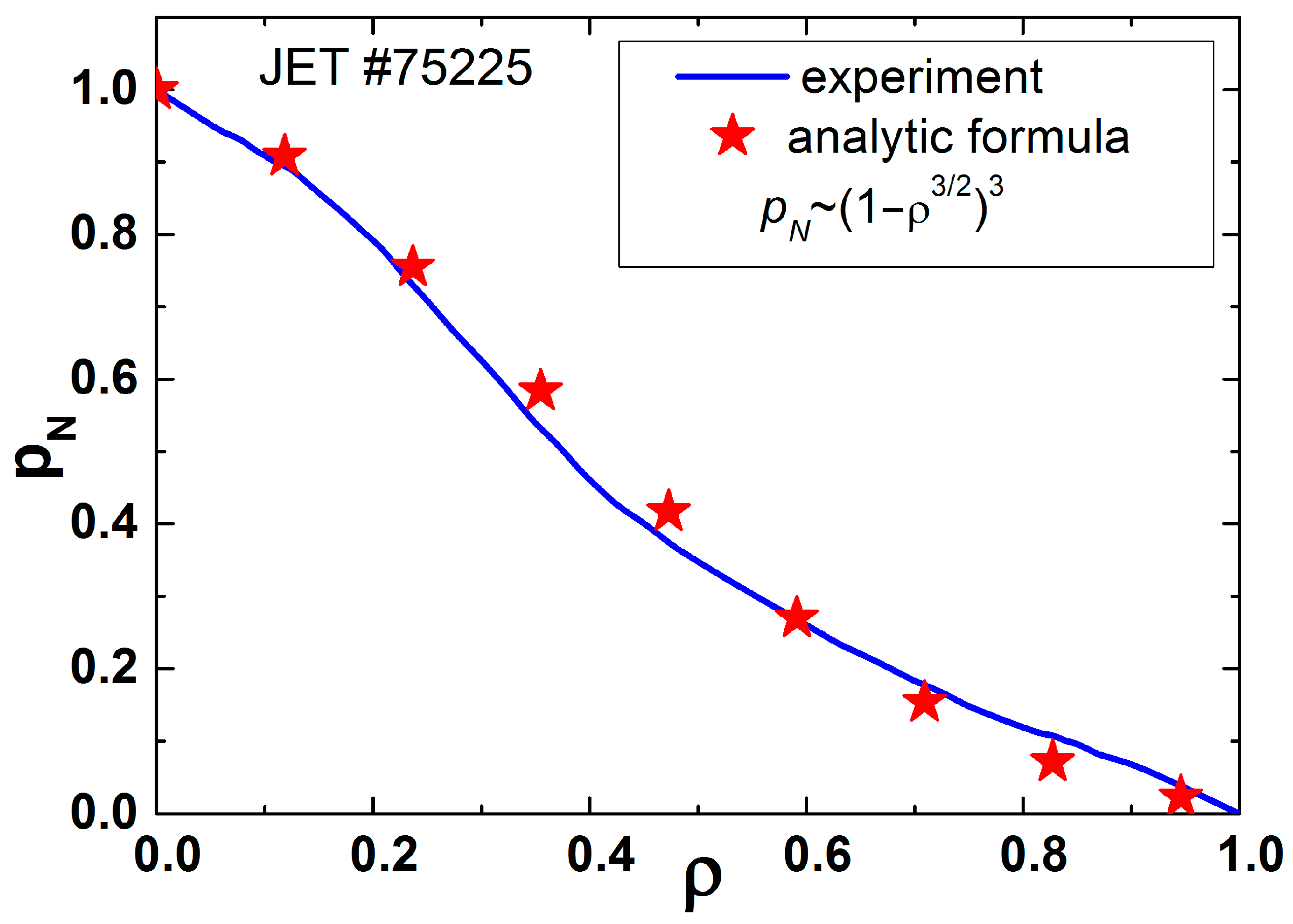
3.1. Conservation of the Normalized Pressure Profile

The most unexpected and impressive result obtained in tokamaks in 1980 is the existence of a universal pressure profile, pN() = p()/p(0) [4,5,6,7,8,9], where is the normalized radius. This result is the evidence of the plasma self-organization. It was not immediately understood, and many groups of scientists still do not take into account this experimental fact when explaining the physical processes in tokamak plasmas. Figure 3 [10] shows the results of measurements of the normalized pressure profiles for different regimes in different tokamaks, and the theoretical curve calculated by K.S. Dyabilin, without a toroidal effect, which shifts the curves in the core. This curve is a good fit for normalized pressure profiles in discharges without pronounced internal barriers. Figure 4 shows that typically for low-density discharges with ohmic heating (OH), T e / T e 0 = n e / n e 0 2   . It is true, when the OH power deposits in accordance with the self-consistent pressure profile.

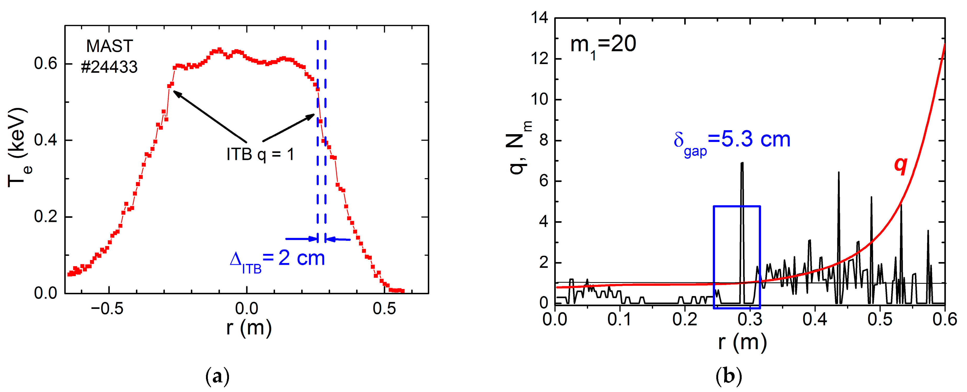
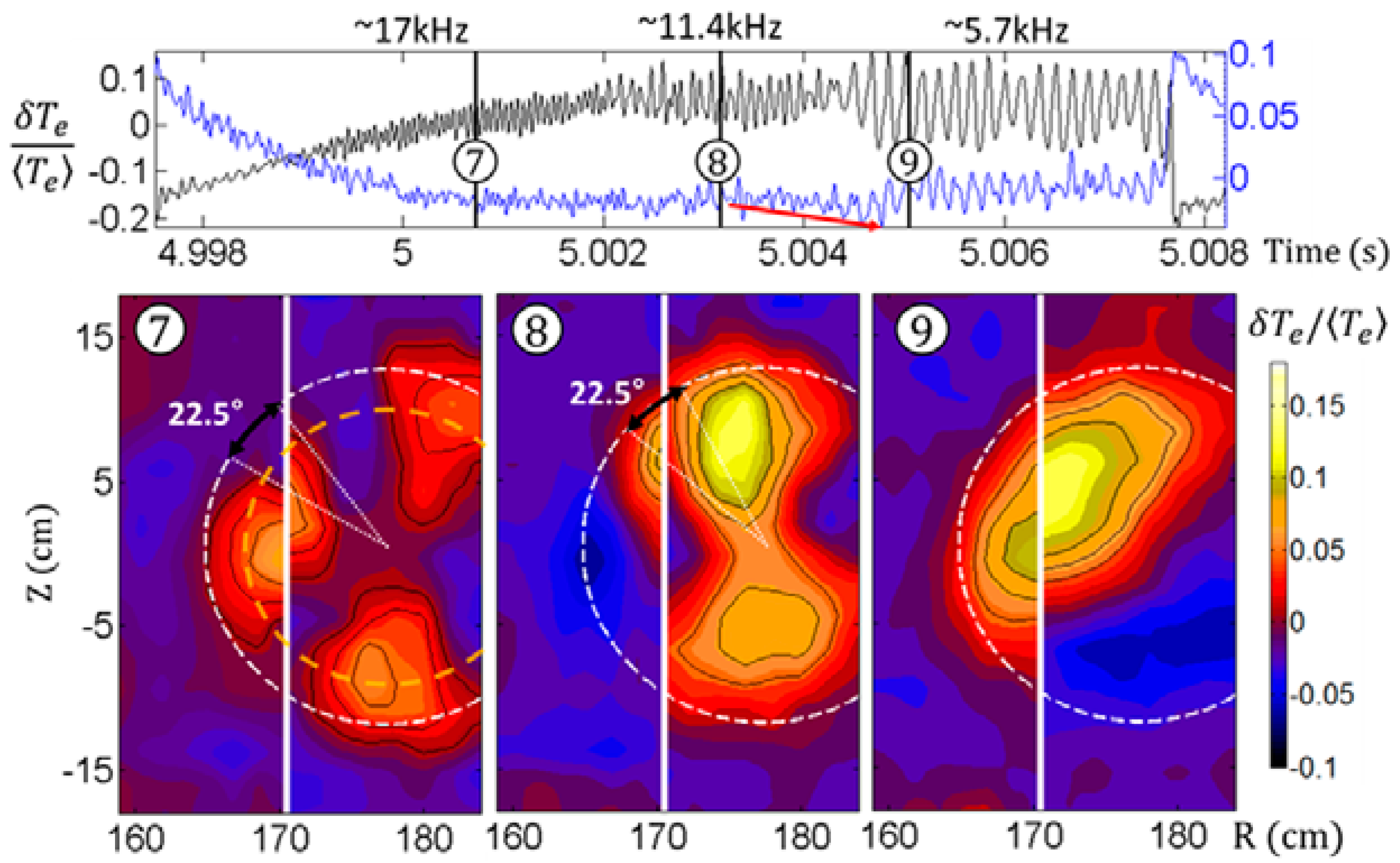
3.2. Islands and Barriers: Two Sides of the Same Phenomenon

In many experiments, where the formation of barriers and islands have been studied, an unexpected result has been found: barriers and islands always formed together. However, for small barriers, islands have high numbers m, and for their registration, diagnostics with a high temporal and spatial resolution are necessary. So, sometimes, islands in small barriers are not seen. Figure 5 shows the result of the gap creation on the MAST tokamak, and, consequently, the barrier on the magnetic surface q = 1 [14].
On T-10 tokamak, the application of off-axis electron cyclotron resonance (ECR) heating and a fast ramp-up of plasma current allow us to form a gap on the magnetic surface q = 3/2, Figure 6, [15]. On the inner chords (r = 13.3 cm), periodic temperature drops are seen (measured using ECE) corresponding to internal disruptions. Harmonic oscillations corresponding to the island q = 3/2 are visible on the created barrier at r = 19 cm. Simultaneous decreases of Te on the inner chords (r = 13.3 cm), and rises of Te on the outer chords (r = 23 cm) relative to the barrier (gap) are seen.
On the contrary, in experiments on TEXTOR [13] and KSTAR [16], the island m/n = 2/1 was generated and the formation of a barrier was observed. Figure 7 shows the result obtained by M. Kantor [17], who used multi-pulse Thomsom Scattering diagnostics with high spatial and temporal resolution. The structure of the magnetic island is shown in isotherms, lines of constant density, and isobars. In the latter case, the barrier is clearly visible on the outer side of the island (blue area).
If we try to stabilize the island using ECR heating or current drive, we destruct the barrier, always located on the outer side of the island [9]. Thus, we may conclude that the formation of the barrier and the island are obviously two sides of the same phenomenon.
The increased pressure gradient (barrier) results in a bootstrap current. The Fmin condition requires fragmentation of the bootstrap current layer into the local islands. Similarly, the layer of mercury, owing to a high-surface tension, will be fragmented into balls.

3.3. Remarks about Fluxes Γ0 and Γ1

The coefficient χ0 was found in experiments with unperturbed self-consistent plasma in the T-10 tokamak. It was constant over the radius and independent of the power deposited into the plasma. The coefficient χ0, found in T-10, allows us to calculate the best energy confinement in various tokamaks. Figure 8 from [18] shows the relationship between the calculated and measured energy store for the highest performance discharges obtained in JET, AUG, JT-60U, DIII-D, and KSTAR tokamaks. It is easy to see that the experimental value of the energy store never exceeds the calculated value (within the measurement accuracy).
The flux Γ1 is more sophisticated. We know that Γ1 is interrupted in gaps that confirm its MHD origin. It was shown in several papers, e.g., [19,20] that the existence of this flux is correlated with the registration of quasicoherent modes. Although nobody has directly observed the island structure of this flux, indirect indications exist. An analysis of TS measurements allows for observing systematic fluctuations beyond the island [21]. Authors claim that fluctuations of ne and pe on magnetic surfaces have distinct periodic structures. Possibly, they form convective cells, which contribute to electron transport in the whole plasma. However, the direct observations of the islands supporting Γ1 are desirable, which is also feasible with modern diagnostics.
In T-10 experiments [10], the ECR heating was performed at very low level of radiation losses, which can be achieved after lithization of the chamber walls. The energy confinement was so low that the input of megawatt EC power could not increase the stored energy above the level received in the preliminary OH phase. Seeding of the radiant gas restored the confinement, if the flux Γ1 was completely blocked. The edge pressure gradient ∇p(r) increases, and the total confinement improves up to the level of the self-organized plasma.
The paper [22] analyzes the island above the barrier q = 1 in the time interval between internal disruptions (sawtooth oscillations). Figure 9 shows that as the barrier rises from zero immediately after the internal disruption, the number of observed islands m changes from m = 3 (higher mode numbers are difficult to detect) to m = 1 when the barrier is restored Time instants for images of magnetic islands are marked by numbers 7, 8 and 9 in circles.
If the internal transport barrier exists in the plasma, then the edge ∇p can correspond to the best confinement. An increase in the heat flux leads to the appearance of internal disruptions (see Figure 6), which expel portions of energy from the core, inside the barrier, to the plasma edge.
An increase in the possible plasma energy store by creating several internal barriers was obtained in many experiments by reducing the value of dq/dr over a large area of plasma. Some authors call them “advanced tokamak” or “hybrid” regimes [23,24,25,26,27,28], but we believe that the method of programming the q(r) profile is not essential, and they are the same regimes. Figure 10 shows the pressure profile for such a high-confinement regime [29]. We see that the profile coincides with the self-consistent profile, and since the flow Γ1 is blocked, the plasma at the edge has an unperturbed coefficient χ0. This determines its confinement as in the best self-organized case.

4. Conclusions

In general, we can say that experiment confirms the above picture of physical processes in the self-organized tokamak plasmas. Self-organization fundamentally changes the processes occurring in plasma.
Small-scale instabilities, vortices, waves, and flows, which we tried to make responsible for the energy confinement, turn out to be connected only by the process of minimizing their activity level, creating the most compact MHD configurations in the plasma, corresponding to the minimum of free energy.
The resulting MHD system responds to external impacts by forming new subsystems, new islands, or a chain of small islands so that their interaction can increase the radial energy flux. Our goal is to obtain self-consistent plasma with minimal distortion of the pressure profile. Under certain conditions, islands can contribute to obtaining the best confinement. The best possible confinement for a given parameter can be calculated simply and reliably without scalings. We have reliably obtained this regime; therefore, it is necessary to understand the physical processes that control the behavior of such a system.

Author Contributions

K.A.R.: writing—original draft preparation; S.E.L.: writing—review and editing. All authors have read and agreed to the published version of the manuscript.

Funding

This research was funded by the Russian Science Foundation, grant number 23-72-00042.

Institutional Review Board Statement

Approved by Kurchatov Institute. Permission No 42-04/708 at 12.04.2023.

Informed Consent Statement

Not applicable.

Data Availability Statement

Not applicable.

Acknowledgments

Authors thank V.F. Andreev, A.Y. Dnestrovskij and N.V. Kasyanova for their assistance.

Conflicts of Interest

The authors declare no conflict of interest.

References

  1. Prigogine, I.; Nicolis, G. Self-Organization in Non-Equilibrium Systems; Wiley: Hoboken, NJ, USA, 1977; ISBN 0-471-02401-5. [Google Scholar]
  2. Taylor, J.B. Relaxation of toroidal plasma and generation of reverse magnetic fields. Phys. Rev. Lett. 1974, 33, 1139–1141. [Google Scholar] [CrossRef]
  3. Dyabilin, K.S.; Razumova, K.A. Interpretation of tokamak self-consistent pressure profiles. Nucl. Fusion 2015, 55, 053023. [Google Scholar] [CrossRef]
  4. Esiptchuk, Y.V.; Razumova, K.A. Investigation of plasma confinement on Soviet tokamaks. Plasma Phys. Control. Fusion 1986, 28, 1253. [Google Scholar] [CrossRef]
  5. Weisen, H.; Behn, R.; Furno, I.; Moret, J.-M.; Sauter, O.; The TCV Team. ‘Profile consistency’ features in shaped sawtoothing ohmic TCV plasmas. Plasma Phys. Control. Fusion 1998, 40, 1803. [Google Scholar] [CrossRef]
  6. Melnikov, A.V.; Eliseev, L.G.; Pastor, I.; Herranz, J.; Hidalgo, C.; Fujisawa, A.; Minami, T.; Razumova, K.A.; Dnestrovskij, Y.N.; Lysenko, S.E.; et al. Pressure profile shape constancy in L-mode stellarator plasmas. In Proceedings of the 34th EPS Conference on Plasma Physics, Warsaw, Poland, 2–6 July 2007; Volume 31F, p. P-2.060. Available online: http://ocs.ciemat.es/EPS2007/pdf/P2_060.pdf (accessed on 9 May 2023).
  7. Razumova, K.A.; Andreev, V.F.; Dnestrovskij, A.Y.; Kislov, A.Y.; Kirneva, N.A.; Lysenko, S.E.; Pavlov, Y.D.; Poznyak, V.I.; Shafranov, T.V.; Trukhina, E.V.; et al. The main features of self-consistent pressure profile formation. Plasma Phys. Control. Fusion 2008, 50, 10500. [Google Scholar] [CrossRef] [Green Version]
  8. Razumova, K.; Andreev, V.; Kislov, A.; Kirneva, N.; Lysenko, S.; Pavlov, Y.; Shafranov, T.; Donné, A.; Hogeweij, G.; Spakman, G.; et al. Tokamak plasma self-organization and the possibility to have the peaked density profile in ITER. Nucl. Fusion 2009, 49, 065011. [Google Scholar] [CrossRef]
  9. Razumova, K.; Andreev, V.; Eliseev, L.; Kislov, A.; La Haye, R.; Lysenko, S.; Melnikov, A.; Notkin, G.; Pavlov, Y.; Kantor, M. Tokamak plasma self-organization—Synergetics of magnetic trap plasmas. Nucl. Fusion 2011, 51, 083024. [Google Scholar] [CrossRef]
  10. Razumova, K.A.; Dremin, M.M.; Kasyanova, N.V.; Kirneva, N.A.; Klyuchnikov, L.A.; Krupin, V.A.; Krylov, S.V.; Lysenko, S.E.; Notkin, G.E.; Sarychev, D.V.; et al. Energy confinement in self-organised tokamak plasma (without transport barriers). Plasma Phys. Rep. 2020, 46, 337–348. [Google Scholar] [CrossRef]
  11. Gryaznevich, M. Experiments on ST40 at high magnetic field. Nucl. Fusion 2022, 62, 042008. [Google Scholar] [CrossRef]
  12. Kurskiev, G.; Miroshnikov, I.; Sakharov, N.; Gusev, V.; Petrov, Y.; Minaev, V.; Balachenkov, I.; Bakharev, N.; Chernyshev, F.; Goryainov, V.; et al. The first observation of the hot ion mode at the Globus-M2 spherical tokamak. Nucl. Fusion 2022, 62, 104002. [Google Scholar] [CrossRef]
  13. Kantor, M.Y.; Donné, A.J.H.; Jaspers, R.; van der Meiden, H.J. Thomson scattering system on the TEXTOR tokamak using a multi-pass laser beam configuration. Plasma Phys. Control. Fusion 2009, 51, 055002. [Google Scholar] [CrossRef]
  14. Razumova, K.A.; Timchenko, N.N.; Dnestrovskij, A.Y.; Lysenko, S.E. Mechanisms governing radial heat fluxes in tokamak plasma. Plasma Phys. Rep. 2016, 42, 809–817. [Google Scholar] [CrossRef]
  15. Razumova, K.A.; Andreev, V.F.; Bel’bas, I.S.; Gorshkov, A.V.; Dnestrovskij, A.Y.; Dyabilin, K.S.; Kislov, A.Y.; Lysenko, S.E.; Notkin, G.E.; Timchenko, N.N.; et al. Formation of an internal transport barrier and magnetohydrodynamic activity in experiments with the controlled density of rational magnetic surfaces in the T-10 tokamak. Plasma Phys. Rep. 2013, 39, 691–697. [Google Scholar] [CrossRef]
  16. Choi, M.J.; Kim, J.; Kwon, J.-M.; Park, H.K.; In, Y.; Lee, W.; Lee, K.D.; Yun, G.S.; Lee, J.; Kim, M.; et al. Multiscale interaction between a large scale magnetic island and small scale turbulence. Nucl. Fusion 2017, 57, 126058. [Google Scholar] [CrossRef] [Green Version]
  17. Razumova, K.A.; Andreev, V.F.; Eliseev, L.G.; Kantor, M.Y.; Kasyanova, N.V.; Lysenko, S.E.; Melnikov, A.V. Physical processes determining plasma confinement in tokamaks with presence of transport barriers from the position of self-organization. Plasma Phys. Control. Fusion 2021, 63, 055003. [Google Scholar] [CrossRef]
  18. Razumova, K.A.; Kasyanova, N.V.; Andreev, V.F.; Lysenko, S.E. Analysis of the highest energy confinement in tokamaks based on thermodynamic approach. Plasma Phys. Control. Fusion 2022, 64, 125007. [Google Scholar] [CrossRef]
  19. Lee, W.; Lee, J.; Lee, D.-J.; Park, H.K. Study of the origin of quasi-coherent modes in low-density KSTAR ECH plasmas. Nucl. Fusion 2021, 61, 016008. [Google Scholar] [CrossRef]
  20. Arnichand, H.; Citrin, J.; Hacquin, S.; Sabot, R.; Krämer-Flecken, A.; Garbet, X.; Bourdelle, C.; Bottereau, C.; Clairet, F.; Giacalone, J.C.; et al. Identification of trapped electron modes in frequency fluctuation spectra. Plasma Phys. Control. Fusion 2016, 58, 01437. [Google Scholar] [CrossRef] [Green Version]
  21. Kantor, M.Y.; Krämer-Flecken, A.; Soldatov, S.; The TEXTOR Team. Fine structure and dynamics of rotating magnetic islands in the TEXTOR tokamak. In Proceedings of the 37th EPS Conference on Plasma Physics, Dublin, Ireland, 21–25 June 2010; Volume 34A, p. P4.134. Available online: http://ocs.ciemat.es/EPS2010PAP/pdf/P4.134.pdf (accessed on 9 May 2023).
  22. Choe, G.H.; Yun, G.S.; Nam, Y.; Lee, W.; Park, H.K.; Bierwage, A.; Domier, N.C.; Luhmann, C.W., Jr.; Jeong, J.H.; Bae, Y.S.; et al. Dynamics of multiple flux tubes in sawtoothing KSTAR plasmas heated by electron cyclotron waves: I. Experimental analysis of the tube structure. Nucl. Fusion 2015, 55, 013015. [Google Scholar] [CrossRef]
  23. Hobirk, J.; Imbeaux, F.; Crisanti, F.; Buratti, P.; Challis, C.D.; Joffrin, E.; Alper, B.; Andrew, Y.; Beaumont, P.; Beurskens, M.; et al. Improved confinement in JET hybrid discharges. Plasma Phys. Control. Fusion 2012, 54, 095001. [Google Scholar] [CrossRef] [Green Version]
  24. Garcia, J.; Giruzzi, G.; JET EFDA Contributors. On the different physical mechanisms for accessing hybrid scenarios on JET. Nucl. Fusion 2013, 53, 043023. [Google Scholar] [CrossRef]
  25. Reisner, M.; Fable, E.; Stober, J.; Bock, A.; Bañon Navarro, A.; Di Siena, A.; Fischer, R.; Bobkov, V.; McDermott, R.; The ASDEX Upgrade Team. Increased core ion temperatures in high-beta advanced scenarios in ASDEX upgrade. Nucl. Fusion 2020, 60, 082005. [Google Scholar] [CrossRef]
  26. Luce, T.; Challis, C.; Ide, S.; Joffrin, E.; Kamada, Y.; Politzer, P.; Schweinzer, J.; Sips, A.; Stober, J.; Giruzzi, G.; et al. Development of advanced inductive scenarios for ITER. Nucl. Fusion 2014, 54, 013015. [Google Scholar] [CrossRef] [Green Version]
  27. Gao, X.; Zhang, T.; Wu, M.; Li, G.; Zeng, L.; The EAST Team. Recent results of fusion triple product on EAST tokamak. Plasma Sci. Technol. 2021, 23, 092001. [Google Scholar] [CrossRef]
  28. Na, Y.-S.; Lee, Y.; Byun, C.-S.; Kim, S.; Lee, C.-Y.; Park, M.; Yang, S.; Kim, B.; Jeon, Y.M.; Choi, G.; et al. On hybrid scenarios in KSTAR. Nucl. Fusion 2020, 60, 086006. [Google Scholar] [CrossRef]
  29. Razumova, K.A.; Lysenko, S.E.; Timchenko, N.N. Transport barriers and self-organization of plasmas. Probl. Atom. Sci. Techn. Ser. Thermonucl. Fusion 2016, 39, 78–87. [Google Scholar] [CrossRef]
Figure 1. Sketch of pressure distribution in a plasma with island. The red line is the self-consistent pressure profile in the main system. The total pressure profiles for plasma with islands of different sizes are shown by the blue, black and green lines. Below, at a radius, where the proposed island is placed, possible variants of the pressure profile in the island are shown by corresponding colours.
Plasma 06 00028 g001
Figure 2. Sketch of emerging islands and the radial heat flux Γ1. The red area marks their reconnection. There must be an ergodization of the MHD structure. Yellow are destroyed magnetic surfaces on the edge of the island.
Plasma 06 00028 g002
Figure 3. Normalized pressure profiles for different regimes in different tokamaks. Solid curve is the theoretical calculation of a self-consistent profile by K.S. Dyabilin. Adapted with permission from [10]. Copyright 2020 by Pleiades Publishing, Ltd.
Plasma 06 00028 g003
Figure 4. Normalized profiles of Te(r), measured by multichannel ECE diagnostics (squares), and ne(r)2, measured by multichannel interferometer (red line) in T-10. In the central region, Te profile is flattened due to sawtooth. The Abel inversion hides the flatness for ne. Adapted with permission from [10]. Copyright 2020 by Pleiades Publishing, Ltd.
Plasma 06 00028 g004
Figure 5. Formation of barrier (ITB) on the electron temperature profile (red line with dots) at the gap zone (dashed lines) in MAST (a). The safety factor q (red line) and the density of rational surfaces limited by the poloidal number m1 = 20 (black line). Blue rectangle marks the calculated gap at q=1. (b). Adapted with permission from [14] Copyright 2016 by Pleiades Publishing, Ltd.
Plasma 06 00028 g005
Figure 6. The island located at the rational surface q = 3/2 (r = 19 cm) is characterized using harmonic oscillations of Te. Internal disruptions are seen beyond the island. Drops at inner chord (r = 13.3 cm) correspond to peaks of Te at outer chord (r = 23 cm) Reprinted with permission from [15]. Copyright 2013 by Pleiades Publishing, Ltd.
Plasma 06 00028 g006
Figure 7. Time evolution of the m/n = 2/1 island formed using pulsed external currents in TEXTOR; (a) isotherms, (b) lines of constant density, and (c) isobars. Red rectangles in (a) mark time instants of TS pulses [17].
Plasma 06 00028 g007
Figure 8. Calculated and experimental stored plasma energy for JET, AUG, JT-60U, DIII-D, and KSTAR tokamaks [18].
Plasma 06 00028 g008
Figure 9. KSTAR tokamak. Time trace of normalized Te fluctuations (upper box) and evolution of the island inside the barrier at q = 1 from m = 3 to m = 1 (lower box) [22].
Plasma 06 00028 g009
Figure 10. Advanced tokamak mode (JET #75225). Experimental normalized profile of plasma pressure. Stars correspond to the approximation formula for a self-consistent pressure profile: p(r)/p(0) = (1 − 3/2)3 [17].
Plasma 06 00028 g010
Disclaimer/Publisher’s Note: The statements, opinions and data contained in all publications are solely those of the individual author(s) and contributor(s) and not of MDPI and/or the editor(s). MDPI and/or the editor(s) disclaim responsibility for any injury to people or property resulting from any ideas, methods, instructions or products referred to in the content.

