1. Introduction
Easy and affordable access to the fast transportation of goods and passengers is a key driver of social and economic growth, yet it also contributes significantly to climate change. Addressing this dilemma, the hyperloop concept emerges as a promising solution, balancing both opportunities and challenges. The vision of connecting cities with the speed of airplanes, the throughput of subways, the flexibility of buses and the ecological footprint of trains is inspiring engineers, researchers and entrepreneurs around the world.
The term hyperloop has become popular since being introduced in a white paper by Elon Musk in 2013 [
1]. Hyperloop refers to a ground-based, public transportation system, operating at the speed of a commercial aircraft. For this, so-called pods travel in a near-vacuum tube to reduce air resistance.
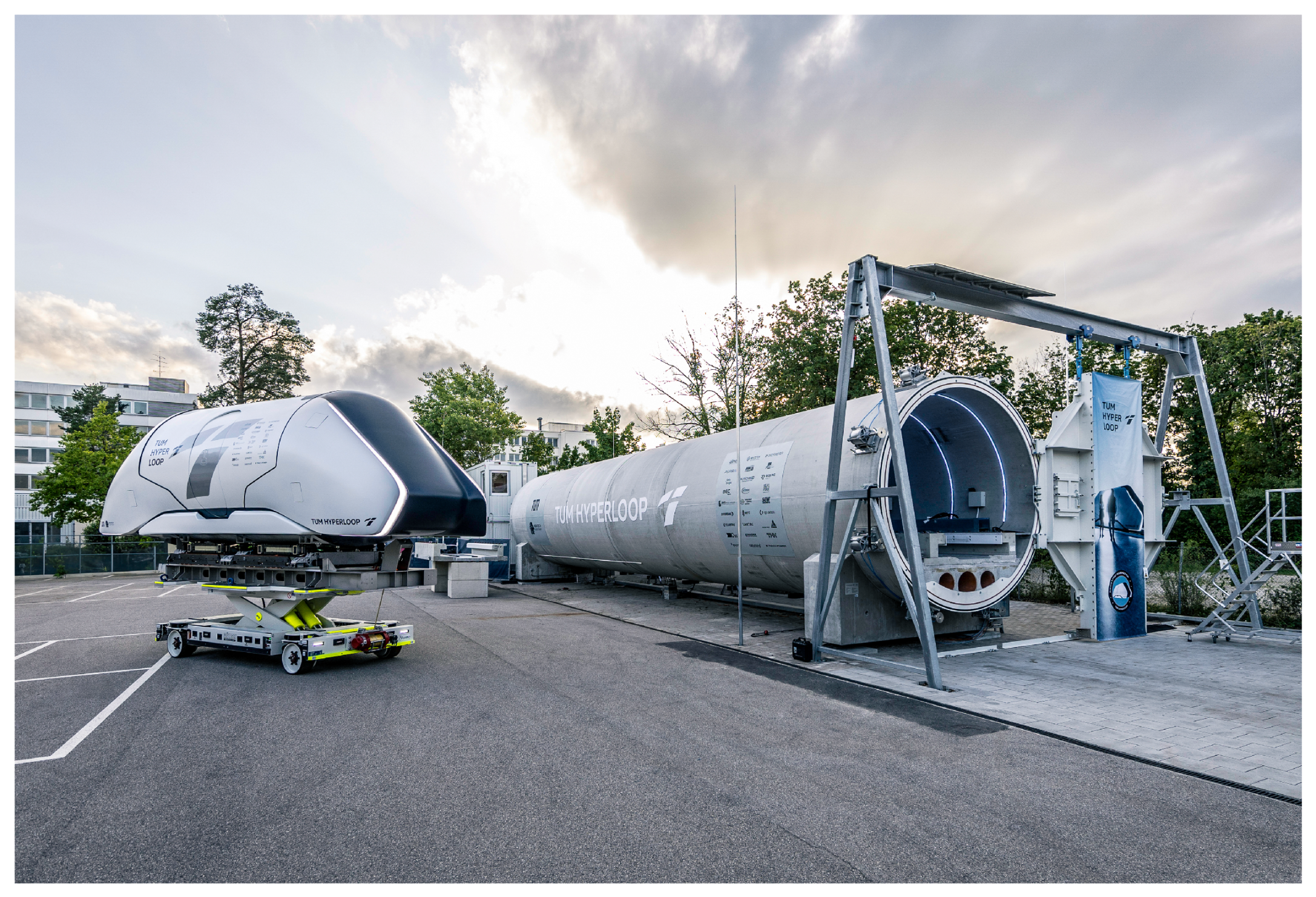
Emerging from a student competition, the TUM Hyperloop research project was founded at the Technical University of Munich in 2019. One major goal was to develop a 24
full-scale demonstrator. The system depicted in
Figure 1 was successfully built, certified and presented in 2023 [
2].
This study addresses the complex challenge of providing a transparent hyperloop concept design as a baseline for further improvement in the community. To achieve the ambitious goals of the TUM hyperloop project, a comprehensive technical concept analysis was imperative. This analysis ensures the selection of the most effective concept from a set of assumptions, directly aligning with the central research question of this work. The process is particularly crucial from an infrastructure perspective, where limited opportunities for iteration necessitate a forward-thinking design approach. Moreover, the increasing demand from regulatory authorities for the standardization of the hyperloop system highlights the need for a transparent process and the meticulous evaluation of each design decision. Given yearlong development cycles, maintaining the coherence and traceability of evolving assumptions and consequent decisions becomes challenging.
The design decision tree (DDT) formalism [
3,
4], not to be confused with the decision tree classifier methodology [
5,
6], was adopted for this purpose. The DDT is an approach commonly used for evaluation and documentation, mainly for complex software architectures [
3,
4], but also in other areas like strategic business development [
7] or psychology [
8]. Based on the formalism, a framework was developed to suit the development of complex hardware designs. The derived structured approach was used to visualize, document and explain the design decisions made during the concept phase and helped to keep the team aligned during the design and construction phases. The DDT formalism supports the incremental design and documentation process but is no replacement for systems engineering approaches.
Several hyperloop companies have published ideas regarding the technical concept of suspension and propulsion. A detailed elaboration is available from the company Hardt Hyperloop [
9], featuring a concept where the pod hangs from the ceiling of the tube and is propelled by a short stator reluctance motor. Additionally to this, maglev concepts, like the German Transrapid [
10], the Japanese Maglev [
11], or the German Transport System Bögl (TSB) [
12], are valuable references for already tested concepts of magnetic suspension and propulsion. Also, in the 1990s, research on the Grumman Superconducting Electromagnetic Suspension design was published [
13,
14], showcasing and testing on a test stand an interesting concept for superconducting propulsion and suspension. The focus of the research community is on specific system challenges, such as aerodynamic drag [
15,
16], with only a few studies [
17] addressing the technical concept of hyperloop.
This work seeks to answer the following specific research questions:
How can a framework be developed to incrementally visualize, document and refine the design processes of complex hardware systems, such as the hyperloop?
In what ways can this framework be effectively applied to enhance the propulsion and suspension system design of the hyperloop concept?
What are the characteristics of the resulting hyperloop system concept, and how does it expand upon and integrate existing ideas to form a coherent and realistic setup?
How can the concept decisions, as implemented in the TUM Hyperloop Demonstrator, be evaluated to provide detailed suggestions for future enhancements?
These questions aim to provide a clear and focused roadmap for the research, breaking down the broad objectives into specific inquiries.
2. Method
According to Ran and Kuusela [
3], the DDT is a formalism for the structured visualization of incrementally specified problem requirements and constraints imposed by earlier decisions. DDTs aim to illustrate the design space and the dependencies between conceptual decisions. The primary goal is the comprehensive documentation and visualization of complex design decisions.
Technical design decisions made during the conceptual phase need to be based on a set of predefined, general design goals. Design decisions will be changed and refined iteratively, ultimately leading to technical requirements and a straw man model as orientation for the development process. Referring to the design goals, all except one option must be rejected. During this process, it is important to analyse the constraints on subsequent design decisions.
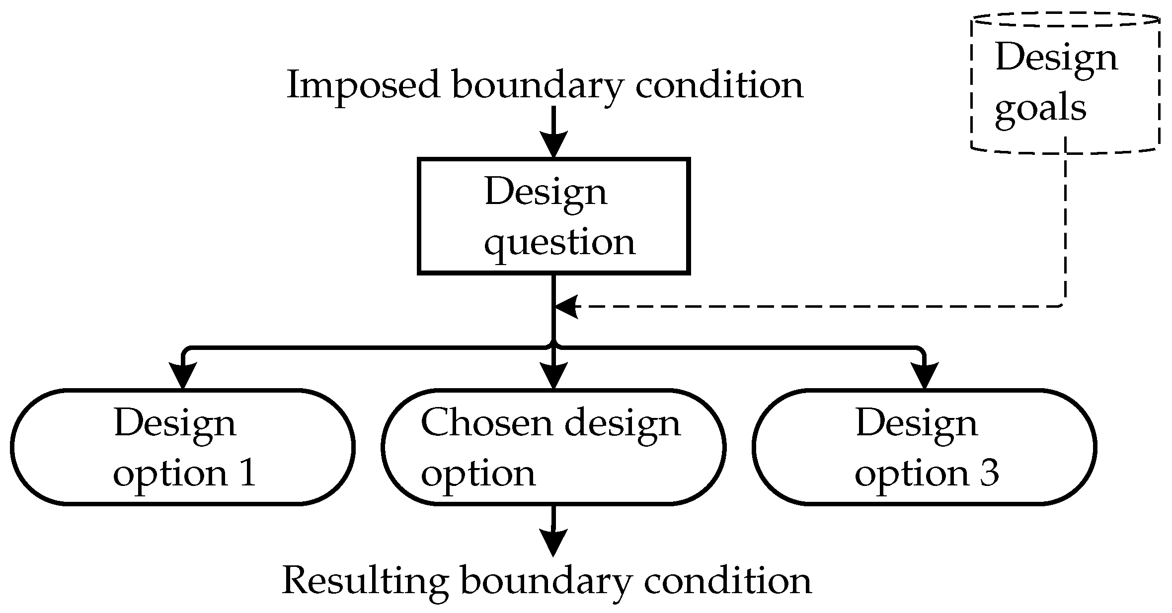
To ensure a cohesive and structured approach, each node of the DDT adheres to the elements outlined in
Figure 2. The following framework is adopted from the established formalisms detailed in [
3,
4].
Specification of driving boundary conditions, requirements or assumptions.
Description of the design question or task. Here, the problem must be specified.
Listing of possible technical design options or alternatives to solve the design question and follow the specified boundary conditions.
Specification of the resulting requirements, boundary conditions or assumptions imposed by the chosen design option. At the same time, this step represents step 1 of the following design decision.
The described steps are repeated for every design decision within the DDT. Particular caution needs to be taken when defining the order of the design decisions. Independent design questions should be tackled in parallel, and should be subsequently followed by increasingly complex and interdependent design questions.
It is recommended to supplement the overview of the DDT with additional documentation. This approach was effectively implemented in the TUM Hyperloop Demonstrator project with the help of a wiki system, while always keeping the DDT as a central overview.
In this project, the DDT proved to be an invaluable tool for tracking changes, clarifying dependencies and providing developers with a clear, comprehensive overview throughout the extensive design process, which involved contributions from numerous individuals. In contrast to traditional, text-based documentation, the DDT facilitated a quicker understanding of design decisions, their underlying rationale and the consequent dependencies for developers. Its user-friendly format also simplified updating information, ensuring that documentation remained coherent and up-to-date, an essential aspect for the certification process.
The subsequent sections will demonstrate the application of this framework, using the TUM Hyperloop Concept as an example.
3. Concept
The presented concept was created over several years and has been subject to continuous evolution. In the following sections, it will be elaborated on in relation to the design goals and derived concept decisions, for the implementation and arrangement of the suspension and propulsion system.
3.1. Design Goals
As mentioned in
Section 1, the overarching goal is to combine the sustainability and throughput of track-based mass transportation systems with the speed of aircraft, as well as the individual flexibility and comfort of road traffic.
For this, the team composed the necessary design goals for the DDT of two components. First, the minimum requirements of the system were set, to enable the basic functionalities:
Velocity: average trip speed of more than 500 /, to compete with regional aircraft.
Throughput: at least 10,000 passengers per hour-direction, to be comparable to modern railway systems.
Energy type: 100% electric operation, to enable sustainable operation.
Automation: pilot-free operation. This is required technically but also improves reliability and operational costs.
Safety: less than 0.04 fatalities per 100 million passenger kilometers, to be comparable to civil aircraft [
18].
Secondly, a set of competing optimization criteria was defined, to guide the design decision process:
Design decisions have to strike a balance between each of the three optimization criteria while sticking to the minimum requirements.
The criteria were chosen from an economic perspective, highlighting the capital expenditures (CAPEX) dominated by the infrastructure, the operational expenditures (OPEX) and the revenue created through passenger tickets and therefore the experience connected with the product.
In general, the design goals impact the design decisions in a way that they point toward a design with simple infrastructure, gathering most of the complexity in the pods. This simplifies maintenance and enables incremental improvements over time.
Based on the design goals, the DDT framework will be applied in the following sections.
3.2. Suspension
Suspending a vehicle safely at an average speed of more than 500
/
is challenging and requires novel solutions. Currently, there are several promising technical solutions under development, each with advantages and disadvantages. The suspension system is mainly responsible for passenger comfort and can account for a large part of the system costs and pod mass.
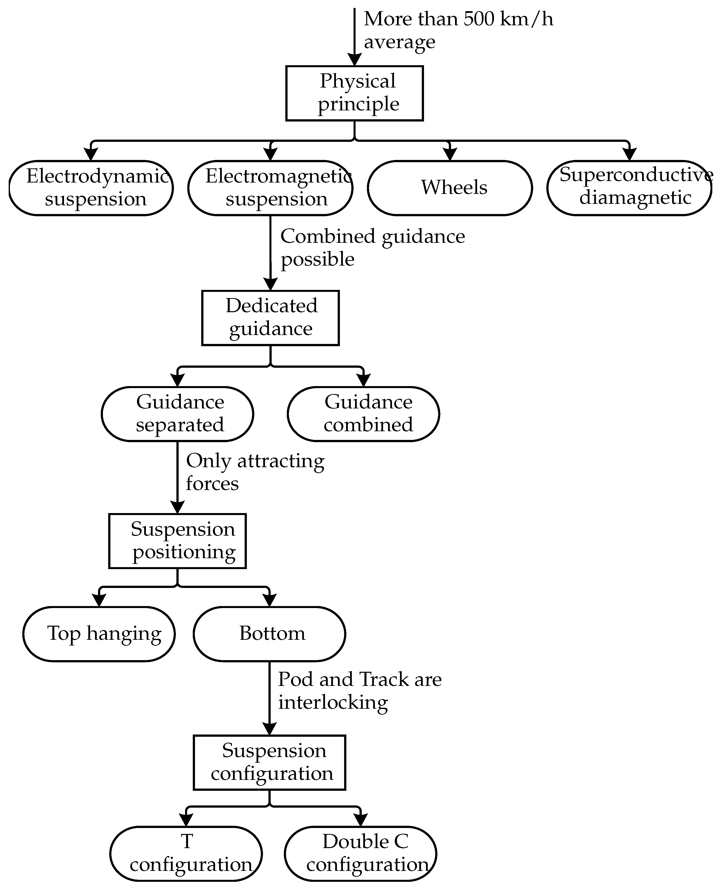
Figure 3 shows the corresponding DDT, leading to the TUM Hyperloop suspension system.
In the following sections, each design decision is explained in detail.
3.2.1. Physical Suspension Principle
One major decision of the hyperloop concept is the suspension type. While wheels are broadly tested and available, the wheel–rail contact increases maintenance costs at the required speed. Other suspension types, like aerodynamic lift using wings or air bearings, are excluded, because of the tight guideway tolerances and the fact that it is difficult to control [
19]. Following the design goal of a 500
/
average speed, the DDT leads to a magnetic levitation system, of which two distinct types are most promising: actively controlled electromagnetic levitation and passively stable electrodynamic levitation. Superconducting diamagnetic levitation is seen as unfeasible, due to the costly integration of either permanent magnets or superconductors into the track. Electrodynamic levitation can work without electronics, but it is prone to undampened vibrations that decrease passenger comfort. Additionally, the magnetic drag, while velocity-dependent, is generally higher than for electromagnetic levitation, and an auxiliary wheeled suspension system is required for low speeds. The chosen electromagnetic levitation comes with a pod hanging from the levitation reaction rails and, thus, detrimental load paths on both tube and pod side. On the other hand, the ride comfort with electromagnetic levitation is largely determined by the controller software, which can be improved over time and adapted to changing guideway conditions.
3.2.2. Lateral Guidance
The DDT shows that, in the case of electromagnetic levitation, the same system can be used to stabilize the pod laterally. For example, the TSB Maglev is featuring this concept successfully. Nevertheless, for high-speed applications, it is recommended to feature separate coils for the guidance system [
20], to improve passenger comfort. Combined solutions for magnetic levitation and guidance either lead to passive lateral stabilization and therefore possible undampened oscillations or decreased efficiency. Especially at high speeds, it is crucial to follow the guideway stiffly and react to inaccuracies, that lower requirements and therefore also the costs of tube and guideway. This justifies the additional complexity, mass and energy consumption onboard in coherence with the target to move costs from the infrastructure to the vehicle. Therefore, separate guidance electromagnets are featured next to the levitation system in the TUM Hyperloop concept.
3.2.3. Suspension Positioning
Apart from the applied suspension principle, different arrangements of the suspension system lead to distinct functionalities. Hanging the pod from the ceiling of the tube enables electromagnetic lane switching with the guidance system at full speed and high switching frequencies, with only one electromagnetic system and without moving parts. Lane switches in a bottom arrangement require either moving parts or an additional suspension system taking over during the lane switching. Moving parts could be on the track side, as a bending beam, or onboard the pod, for example, with laterally moving levitation modules deciding whether to switch or not. Conversely, a floor-mounted design offers independence from the tube, facilitating the easy implementation of the system in various tunnels or tubes, regardless of the manufacturer. As the load path is more direct, structural benefits might also arise. The additional complexity of a second suspension system is mainly concentrated in the pod, while the structural benefits of a floor-mount scale are mainly focused in the infrastructure. Therefore, we decided to use the bottom configuration.
3.2.4. Suspension Configuration
For the bottom configuration, two options are viable: the Transrapid’s T-shaped guideway, where the vehicle wraps around the guideway [
21], or the TSB system, where the guideway is encircling the vehicle [
12] (double C configuration). The T-shaped design necessitates mechanical guideway movement for lane switching, which is less ideal for high-frequency switching and maintenance. With the double C configuration, horizontal lane switching, where one side of the pod swaps the suspension system, for example to an electrodynamic suspension, is feasible. When the passenger module fits between the guideway, vertical lane switching to the top or bottom is also enabled. This can also be realized by an electrodynamic suspension taking over, or alternatively there could be moving parts instead of the additional suspension system. For example, the levitation modules in the pod could be movable laterally to facilitate the switching decision.
3.3. Propulsion
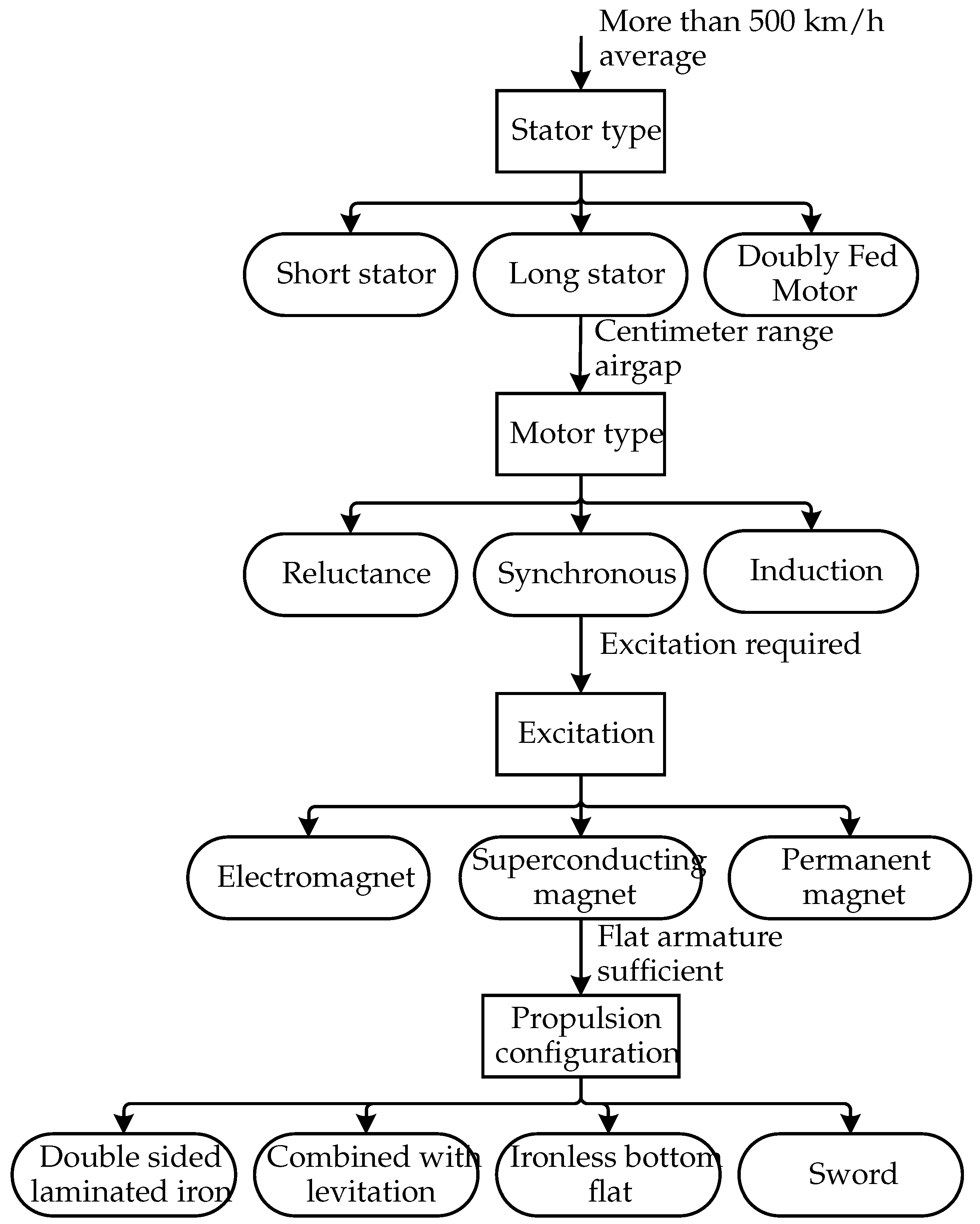
Another pivotal design element within the hyperloop concept is the motor, as illustrated in the corresponding DDT in
Figure 4. Considering the system’s fully electric operation, the propulsion system demands high-power electrical components in the megawatt range. It is crucial to examine the entire powertrain, covering aspects from power transfer and magnetic field excitation to the magnetic interaction and generation of movement.
3.3.1. Stator Type
The determination of active motor components—whether in the pod, the track or both—is a critical decision. While energy recovery is possible, the propulsion system constitutes the largest portion of the system’s energy demand, reaching up to several megawatts. In contrast, the energy requirements for other systems, such as levitation, vacuum or onboard electronics, are significantly lower, typically an order of magnitude less.
Having the active part of the propulsion system onboard is called a short stator. This reduces the amount of copper along the track and enables pods with different velocities to form convoys. In the track, this requires a passive reaction rail and an inductive power supply system, like in the Transrapid [
22]. The transferred power has to be significantly higher than for the Transrapid, to allow for high speed travel. Thermal management in the pod will be a large issue in this case, presumably solvable by sublimation cooling and therefore requiring special vacuum pumps along the track coping with water vapor in the tube. Phase changing thermal batteries exchanged in stations could be an alternative for the cooling problem.
A long stator, on the other hand, handles the high-power electronics on the track side, and, therefore, does not require the extra step of first transferring the energy to the moving vehicle. Also, from a safety perspective, it can be beneficial to have the propulsion system centrally controlled from the infrastructure, while the pods only handle levitation. This makes simultaneous failures less likely and simplifies the requirements of the communication system. Additional energy transmission to the pod is possible if a linear generator is onboard.
With a doubly-fed motor, featuring active windings in both the pod and the track, pods can achieve speed differences, which enable pods to join or leave a convoy at high speed, while keeping the advantages of relatively low heat production on board. It would also be possible to use this system as a short stator during low speed and only during high speed supply power from an additional track-based long stator. At high speed, the short stator can be used to generate energy from the track-based long stator. However, those additional functionalities are not required and, thus, do not justify the additional complexity.
It was therefore decided to feature a long stator motor, supplying the system with grid power and directly accelerating the pod, instead of transferring the energy for acceleration.
3.3.2. Motor Type
With the long stator confirmed, the large airgap is another challenge. To allow for realistic construction tolerances, an airgap in the range of one to two centimeters is necessary. A linear synchronous motor with strong excitation in the pod can cope best with this problem by increasing motor efficiency through stronger magnetic excitation. A long stator induction motor would come with extensive heat in the pod and decreased efficiency due to the large airgap. A long stator reluctance motor, on the other hand, would come with plenty of laminated iron in both the pod and the track, increasing the system cost.
3.3.3. Excitation System
A linear synchronous motor requires a strong excitation system to bridge the large airgaps, compared to rotational machines. Exciting the stator with a strong magnetic field leads to higher voltages and lower currents in the active windings, and therefore a higher efficiency, as well as a decreased amount of copper in the infrastructure. On the other hand, reaching strong magnetic fields at the stator often requires laminated iron in the guideway, increasing the infrastructure costs. Generally, there are three design options available.
Ordinary electromagnets onboard have the advantage that the magnetic field can be turned off, which is beneficial during assembly, transportation, and maintenance. However, the achievable magnetic field strength is comparatively low. Also, electromagnetic excitation can be combined with an electromagnetic levitation system, like in the Transrapid. This concept requires a heteropolar levitation coil arrangement, so there are alternating magnetic poles in driving direction. For high speeds, this leads to more eddy currents in the iron and therefore requires expensive lamination of the iron. This is one reason for separating the levitation and propulsion systems. Other reasons include independent testing and development, as well as the option to implement propulsion in parts of the track only.
With neodymium permanent magnet arrays in a Halbach configuration, stronger magnetic fields are feasible at comparable mass. Additionally, no power is required on the pod side, leading to less heat. However, a significant amount of rare earth material is required. Also, the reachable field strength enables an ironless stator with sensible effort only in a sword configuration, and the magnetic field cannot be turned off during handling and maintenance.
Superconducting excitation promises strong magnetic fields by cooling down the system to cryogenic temperatures and harnessing the superconductive property of certain materials. In contrast to the Japanese L0, high temperature superconductors operate at higher temperatures and require less intensive cooling. Nevertheless, this concept is the most complex and technically challenging design but enables a simple ironless stator. Thus, the concept shifts the complexity and the costs from the tube infrastructure to the pods, aligning with the defined design goals.
3.3.4. Propulsion Configuration
The positioning of the propulsion system also determines the overall concept.
A sword configuration, where the armature windings are positioned like a fin on the ground and the excitation system can act from both sides, often comes with a good efficiency but relatively high costs on the track side. Additionally, this would mean there is no propulsion during a horizontal lane switch and that one lane loses propulsion during a vertical lane switch.
According to [
13], it would also be feasible to combine the propulsion system with a superconducting levitation system, such as excitation. However, a separated homopolar system leads to less plating in the levitation reaction plate and, therefore, to a cost reduction on the track side. Also, the separation eliminates the dependency between suspending and accelerating forces, posing a limit on the feasible acceleration. Additionally, in a separate system, there are no groves in the reaction plate, leading to force ripples and vibrations in the system. Furthermore, independent testing of the systems is enabled, which was especially valuable during the prototyping phase of the Demonstrator. However, it has to be acknowledged that an ironless bottom flat design necessitates a second strong excitation system onboard, which is a notable drawback in terms of onboard mass and power consumption.
In the case of a superconducting excited linear synchronous motor and an electromagnetic suspension in double C configuration, the armature can be positioned centered on the floor. Manufacturing is cost-effective and straightforward in this case. Because of the strong magnetic field, there must not be any ferromagnetic material underneath the excitation, to prevent forces counteracting the levitation. In a vertical lane switch, one switching direction loses propulsion during the switch, which can be counteracted by placing one propulsion system on each side. In this case, it must be distinguished between a propulsion system with laminated iron, which is expensive on the track side, or an air cored system, which is less expensive on the track side but requires extensive excitation.
3.4. Derived Concept Proposal
Combining the findings of
Section 3.2 and
Section 3.3 leads to the TUM Hyperloop Concept, schematically shown in
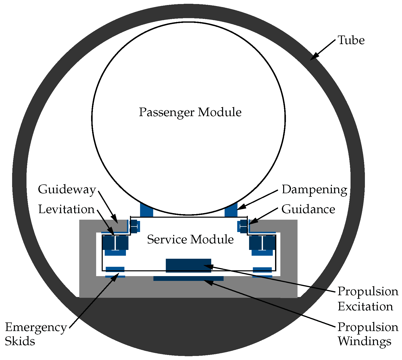
Figure 5. The derived technical baseline concept of a floor-mounted, ironless synchronous motor with superconducting excitation and a homopolar electromagnetic suspension is illustrated.
Within the load-bearing tube, measuring 3.8 m inner and 4.2 m outer diameter in the Demonstrator, the guideway can be positioned precisely. It contains levitation and guidance reaction rails, the armature windings of the propulsion system and landing surfaces for emergency skids. Those skids suspend the pod when the levitation system is turned off and provide a safe braking functionality in case of a levitation failure. The guideway wraps around the service module, which contains the levitation and guidance electromagnets, and the superconducting excitation system. Decoupled by a mechanical dampening system, an airtight passenger module or cargo module is attached. In the Demonstrator, the passenger module has an outer diameter of 2.55 m and weighs about 2 t with four passengers. The mechanical dampening further improves passenger comfort and is independent of the main suspension, which was discussed in
Section 3.2.
On the other hand, the concept also has some drawbacks. The tolerances in the double fit between the levitation reaction rail, the landing surface and the propulsion armature require high precision along the entire guideway. Next to this, there must not be any ferromagnetic material underneath the superconducting excitation system, as the resulting attraction forces would counteract levitation. In the TUM Hyperloop Demonstrator, this is tackled with stainless steel-reinforced concrete. Also, for high-frequency lane switching, an auxiliary system is required to take over suspension during the lane switch. Additionally, one branch loses its propulsion functionality during the lane switch. Due to the long stator, convoys of pods must be assembled in the hubs and pods are only allowed to branch off during the journey.
Nevertheless, the benefits outweigh the disadvantages. The concept comes with a comparably lightweight tube and pod structure, as all forces and tolerances are focused on the floor, even in the case of emergency load cases. Also, the electromagnetic levitation system provides efficient and comfortable suspension that can be improved over time using software. The propulsion system is separated from the suspension and the floor-mount enables cost-efficient manufacturing by molding the windings directly in the guideway, while maintaining the advantage of a wired grid connection to the stator. Horizontal as well as vertical lane switching is feasible with the use of an auxiliary suspension system in the lane switch, enabling flexible route planning according to the requirements.
The presented concept is feasible technically and in terms of safety, fulfilling the design goals defined at the beginning of this section.
4. Evaluation
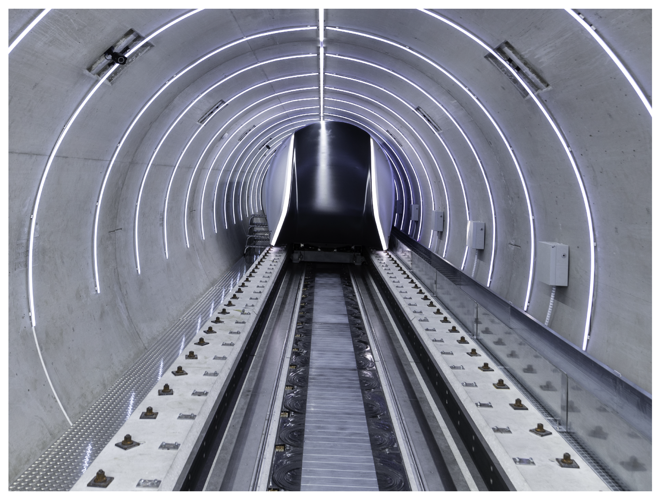
Based on the presented concept, a 24
full-scale Demonstrator was constructed in the south of Munich between late 2022 and mid-2023. Alongside the levitation and propulsion systems, vacuum and safety were also tested. After TÜV Süd safety approval was obtained, it was tested with passengers in vacuum [
2]. A front view of the Demonstrator from within the tube, showing the guideway and the shell of the passenger module, is depicted in
Figure 6.
Compared to the presented concept, the Demonstrator does have three major simplifications. Firstly, the electromagnetic suspension was powered by a DC power supply by means of a cable chain, instead of an onboard battery. This simplified the certification and testing of the prototype. Secondly, a permanent magnet array, instead of the superconducting excitation, was featured in the pod, to speed up the development process. The superconducting excitation will be tested on a separate test wagon in the Demonstrator tube. Thirdly, the auxiliary suspension system for lane switching was not implemented at that point.
The following will provide an evaluation of the presented suspension and propulsion systems, assessing the experiences had on a conceptual level during testing.
The electromagnetic suspension generally worked as expected. Nevertheless, there were several challenges to overcome, and control software is still being improved to reduce vibrations in the pod.
A major challenge that was underestimated when switching from the 1D test stand to the full-scale Demonstrator was the dampening system between the passenger module and the service module. This load change is modeled in the controller as disturbance, increasing the performance requirements of the controller significantly.
Another point that was and is of great scientific importance is the interactions between the systems that are hard to model. The propulsion, levitation and guidance systems interact magnetically, electrically and in software. Plotting the airgap deviation shows that switching on either propulsion or guidance during levitation leads to extra disturbances. In the current state, the controller is capable of handling those extra disturbances, but vibrations are induced that, in some cases, are also noticeable for the passengers.
The self-developed electronic system powering the levitation coils worked seamlessly, until, in winter, an operating temperature of less than 5 °C was reached. This triggered over current protection, probably caused by a change of behavior of the silicon carbide MOSFETs. Several current-limiting measures in the software and hardware fixed this problem.
The emergency skids proved to be helpful for maintenance, testing and certification. They ensured safe suspension and defined braking, even at a complete loss or disconnection of power.
One advantage that became clear only during construction was the separation of the guideway and the tube. It allowed for separate accuracies in both the elements and the independent production of the tube and guideway.
Additionally, in a concrete tube, the anchoring of parts is challenging. The guideway allowed for a screw-through connection of the levitation and guidance rail, promising a stable connection over a long lifetime and, therefore, improved performance compared to a ceiling-mount.
The construction of the propulsion system showed that the air-cored armature might actually not be much more expensive than a laminated steel reaction rail for a short stator reluctance motor plus an inductive power transfer system.
However, the conceptually determined clearance between the levitation reaction rail and the propulsion armature results in a substantial propulsion air gap, necessitating a powerful magnetic excitation.
Moreover, the placement of the enclosed service module is anticipated to have an adverse aerodynamic impact. To address these issues, repositioning the armature to the inner sides of the guideway is being considered. Such a modification would effectively decouple the airgaps of propulsion and levitation, and concurrently create space for improved aerodynamics beneath the pod.
An unforeseen challenge involved the motor identification of the inverter. The off the shelf inverter came with a good hardware specification but required a motor identification that is meant for rotational, iron-cored motors. Due to complicated software with few opportunities for intervention, the initial setup was laborious. For subsequent projects, we are considering the development of our own system, mainly to enable more control over the software.
Another interesting problem occurred during testing under vacuum. At pressure levels under 15 mbar, sometimes the over current protection of the inverter triggered a safe shut down of the propulsion system. The reason for this might be sparking due to the increased susceptibility in this pressure range (Paschen’s Law). A thorough investigation could not locate the exact position of the problem and heavy insulating of likely problematic areas did not resolve the issue.
A final decision on whether or not to pursue the superconductive excited air cored linear synchronous motor will only be possible after the tests with the superconducting excitation system.
5. Discussion
The implementation of the DDT formalism, as outlined in this study, has proven instrumental in the visualization and documentation of the complex development processes inherent in hardware like the Hyperloop. By applying the presented framework specifically to the suspension and propulsion systems, a comprehensive understanding of the design space and the interplay between various design decisions was achieved. The combination of design decisions according to the DDTs leads to the concept proposal in
Figure 5. Notably, the versatility of the DDT methodology holds promise for its applicability across various complex hardware systems, extending beyond the scope of the Hyperloop concept.
The study presented the concept of the TUM Hyperloop Demonstrator and elaborated on the underlying design decisions. The results show that the concept not only is feasible but also proves robust, when integrated into a full-scale demonstrator. The electromagnetic levitation system in the bottom-mount configuration, with a separated guideway in double C configuration, showed promising results in terms of structural simplicity for the infrastructure. Although the superconductive excitation could not yet be tested, the propulsion system does function as planned with a permanent magnet array. The implementation indicated that the air cored synchronous long stator could be built comparably as cheap as a reluctance short stator.
The presented research is limited to a concept-level view of technical aspects, to allow the design of a full-scale Demonstrator. Therefore, several important subsystems like the vacuum system, the heat management system, the communication system, and the life support system were not in the scope of this work. Further publications will touch on specific technical aspects of the Demonstrator, including the suspension and propulsion system, with measurement results and comparisons to initial simulations. We encourage the research community to build upon the presented concept and propose their views. At the current stage of the development, the authors see it as crucial that an open and fact-driven discussion is initiated about the technical concept of the Hyperloop system. Only such a discussion, in combination with gained experience from prototypes, can enable a meaningful path to the standardization of the technique.
In summary, the anticipated advantages of the bottom-mounted configuration with separated levitation and propulsion systems were confirmed and strengthened, in terms of guideway flexibility and structural component integration, by the testing with the full-scale Demonstrator. The concept represents a transparent and unique design for further development in the hyperloop research community.
6. Conclusions
In the present work, we have introduced a method for the visualization and documentation of design decisions in complex hardware systems. This method, we believe, presents a significant contribution to the field, as it provides a structured approach to managing and communicating intricate design processes in large-scale hardware related projects. Additionally, our paper details the design decisions for a viable hyperloop concept that was not only realized in full-scale but also certified for passenger transport. This aspect of our work offers verification of the presented theoretical design principles in a real-world setting, which we consider a notable contribution to the existing body of knowledge. Lastly, we have conducted an evaluation of the concept-level design decisions, incorporating results from the full-scale Demonstrator. This evaluation provides critical insights into the practical challenges and successes experienced during the development of the Hyperloop concept, contributing valuable lessons for future developments in this area.

 ,
, 


