
Effects of Infill Density and Pattern on the Tensile Mechanical Behavior of 3D-Printed Glycolyzed Polyethylene Terephthalate Reinforced with Carbon-Fiber Composites by the FDM Process


Abstract
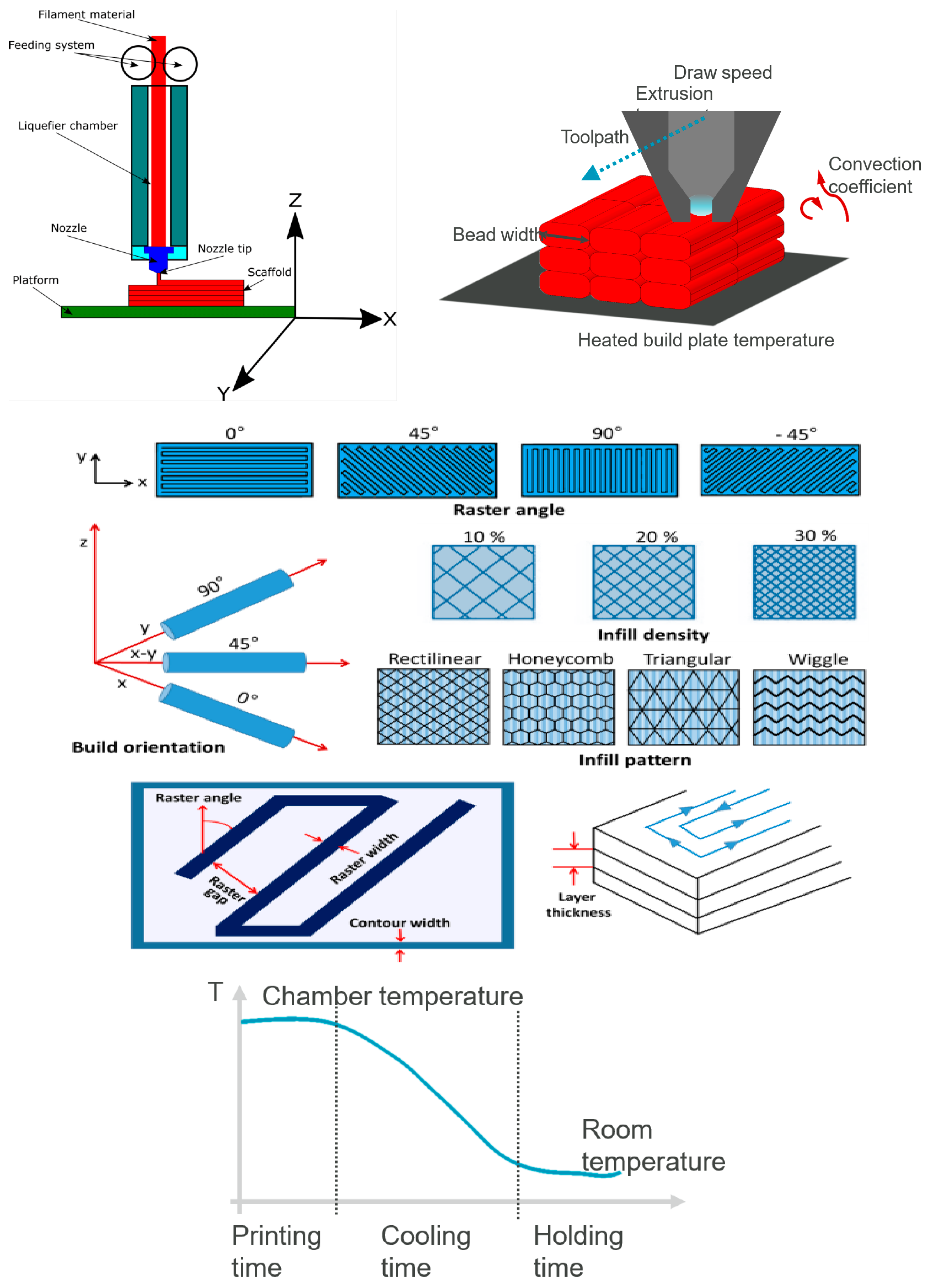
:1. Introduction
2. Materials
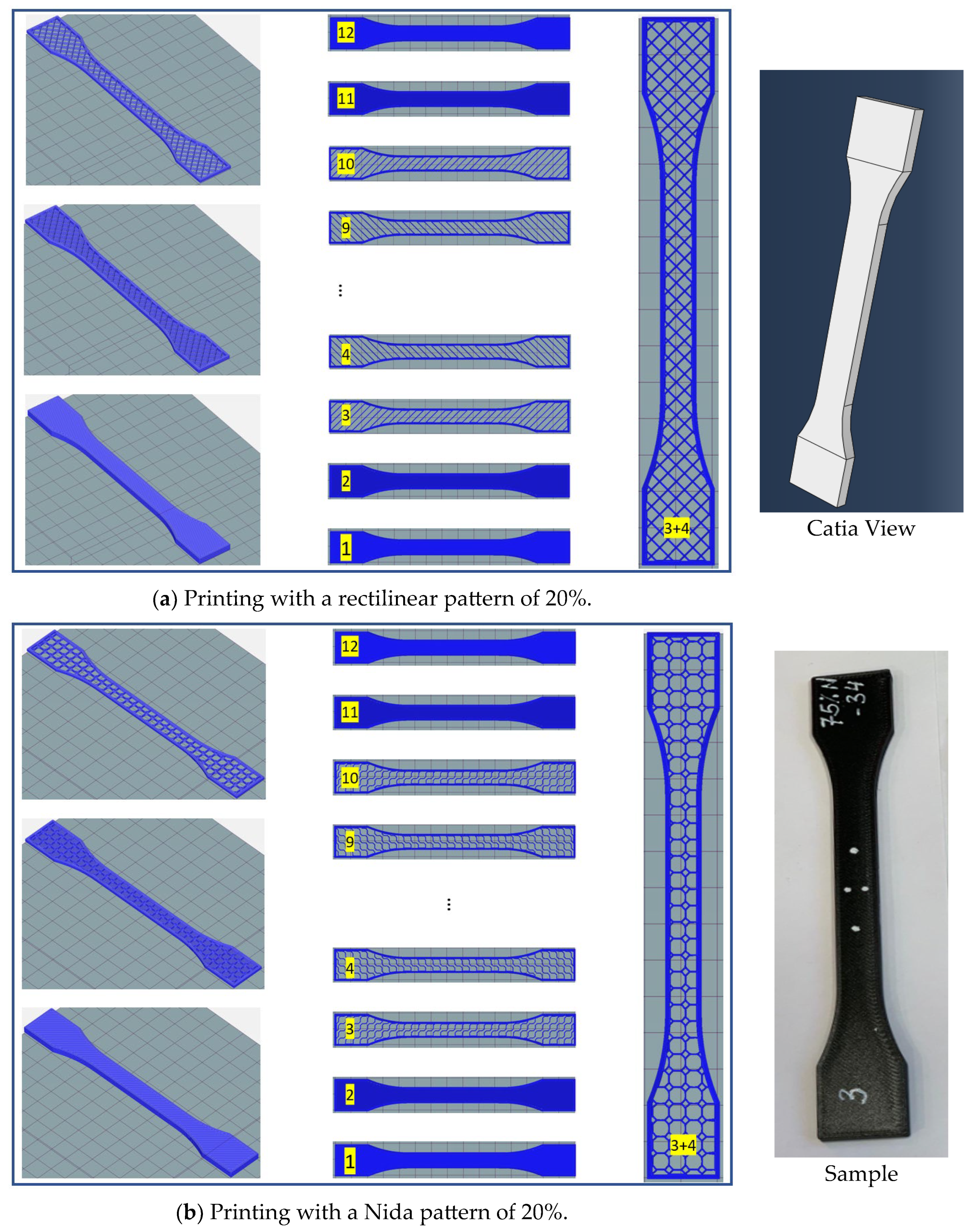
3. Structural Design
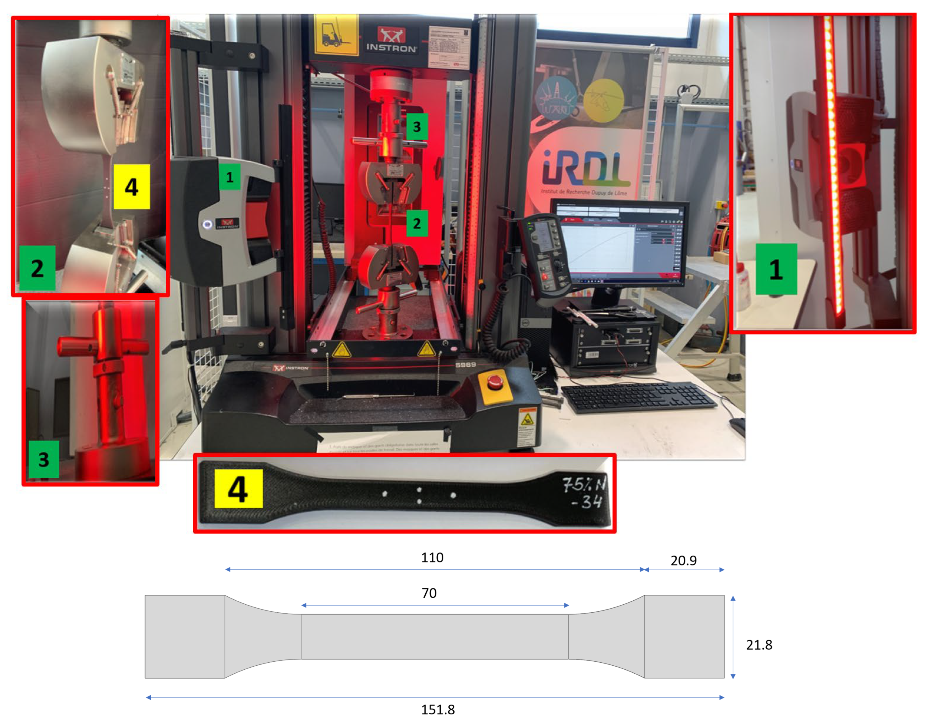
4. Tensile Tests
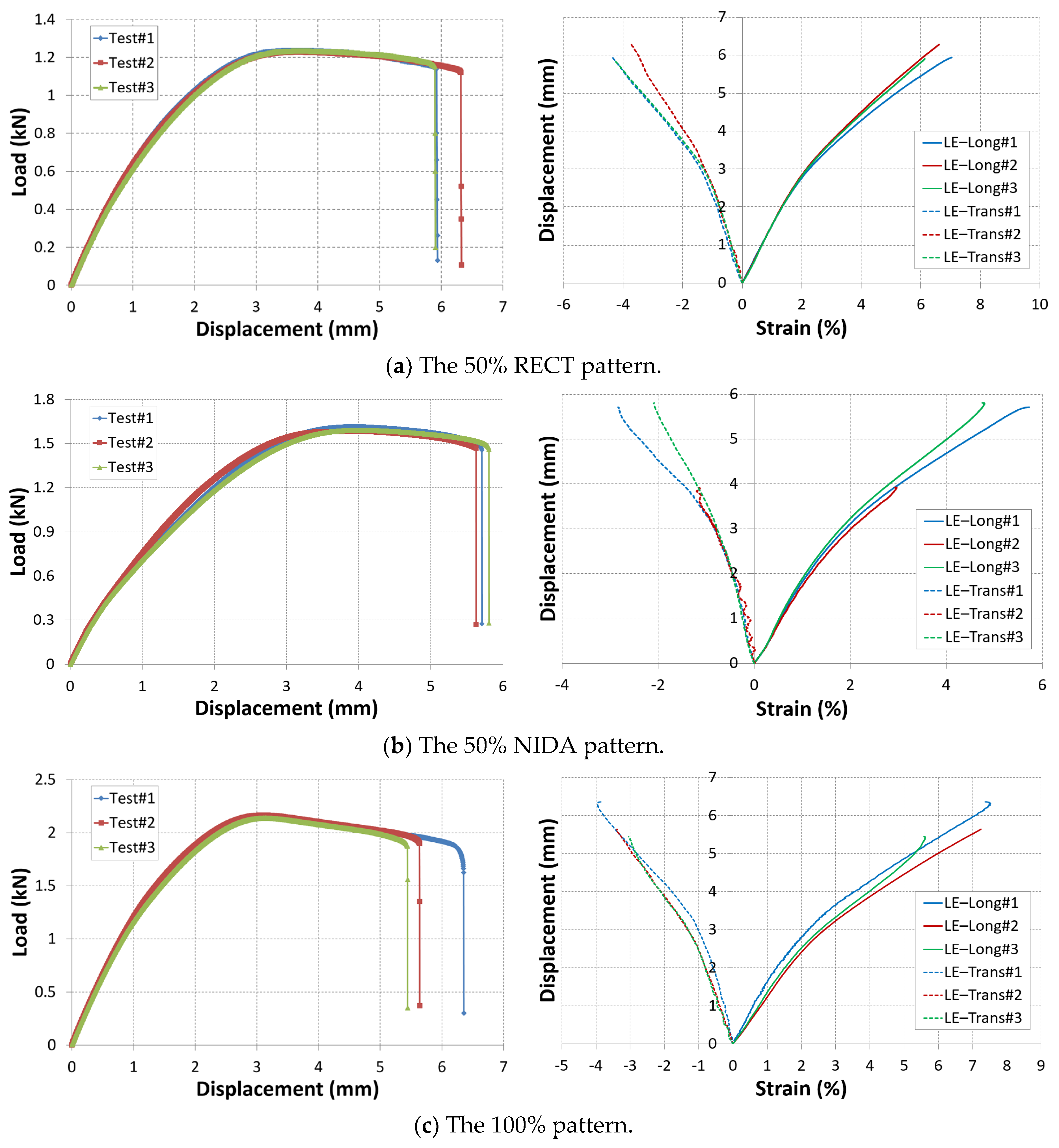
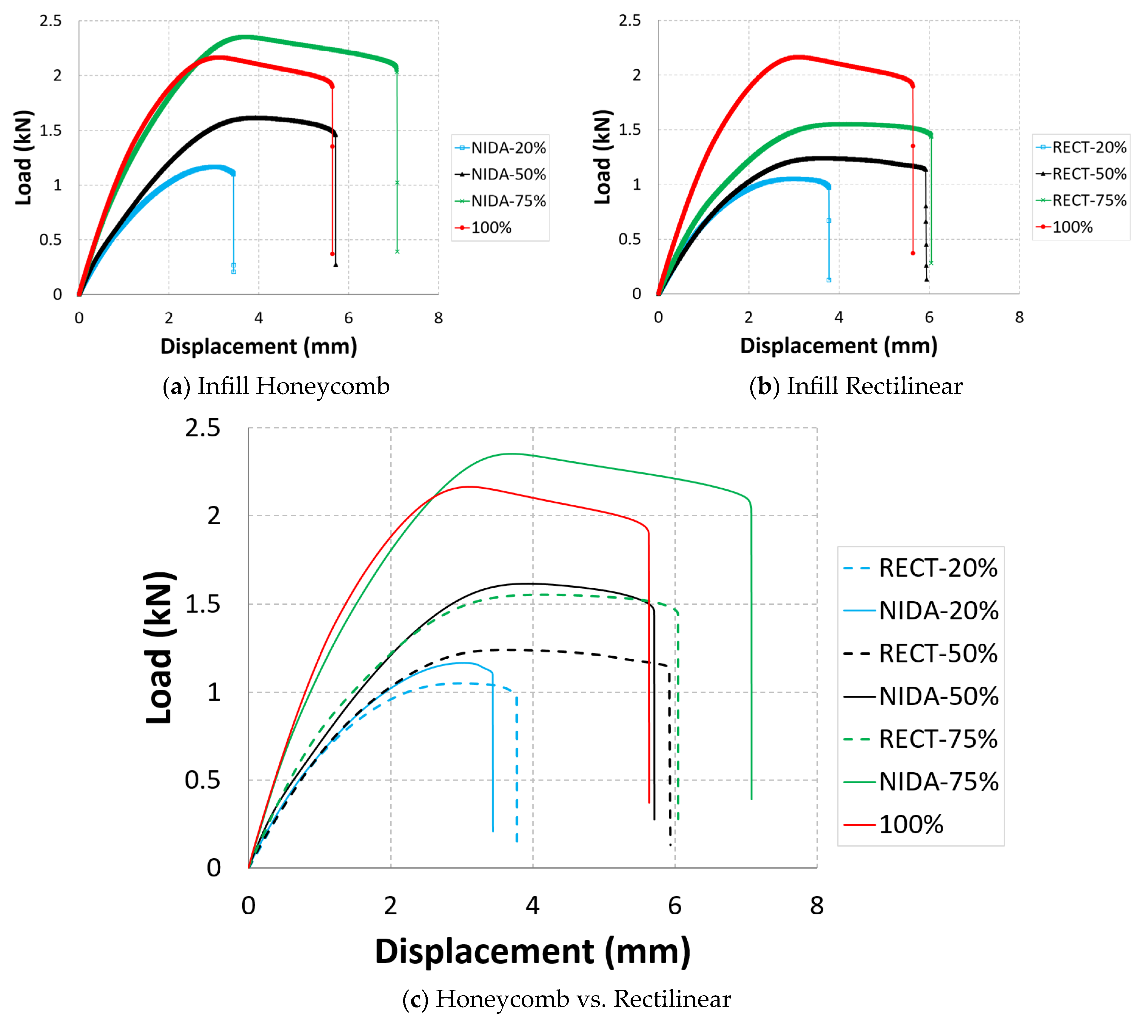
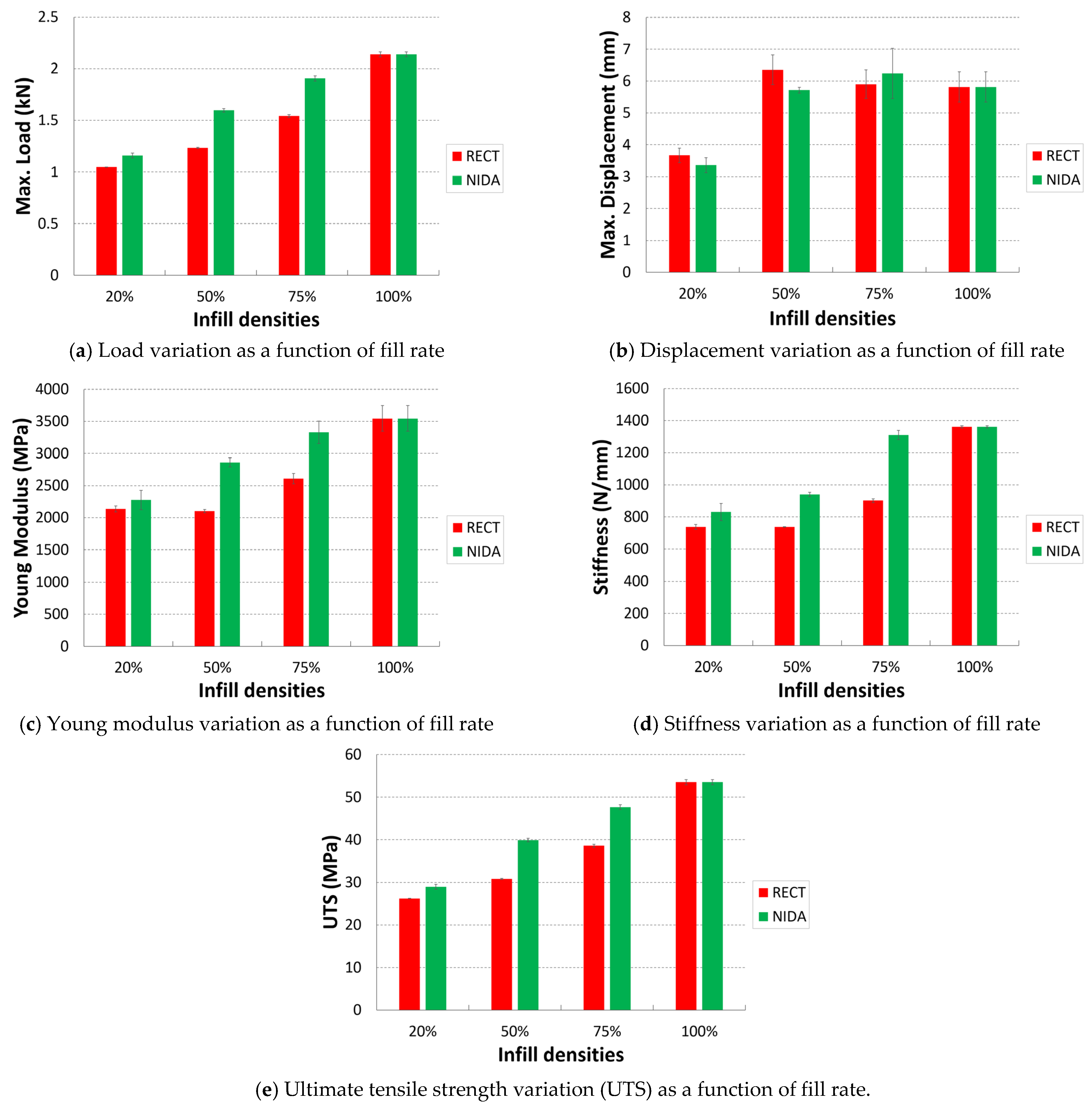
Results
5. Conclusions
- The infill types and densities affect the ultimate tensile strengths and yield strengths.
- The ultimate tensile strengths and yield strengths of all types of infill patterns increase as the density increases from 20% to 75%. Maximum strength is achieved with a 75% infill.
- The results showed that the honeycomb infill pattern had the highest ultimate tensile strength and yield strength when compared to the rectilinear infill.
- Compared to the 100% infill, the honeycomb and rectilinear infill patterns of 75% resulted in slightly lower ultimate tensile strengths.
Author Contributions
Funding
Data Availability Statement
Conflicts of Interest
References
- Grünewald, J.; Parlevliet, P.; Altstädt, V. Manufacturing of thermoplastic composite sandwich structures: A review of literature. J. Thermoplast. Compos. Mater. 2017, 30, 437–464. [Google Scholar] [CrossRef]
- El Moumen, A.; Tarfaoui, M.; Lafdi, K. Additive manufacturing of polymer composites: Processing and modeling approaches. Compos. Part B Eng. 2019, 171, 166–182. [Google Scholar] [CrossRef]
- Rouway, M.; Nachtane, M.; Tarfaoui, M.; Chakhchaoui, N.; Omari, L.E.H.; Fraija, F.; Cherkaoui, O. 3D printing: Rapid manufacturing of a new small-scale tidal turbine blade. Int. J. Adv. Manuf. Technol. 2021, 115, 61–76. [Google Scholar] [CrossRef]
- Daly, M.; Tarfaoui, M.; Chihi, M.; Bouraoui, C. FDM technology and the effect of printing parameters on the tensile strength of ABS parts. Int. J. Adv. Manuf. Technol. 2023, 126, 5307–5323. [Google Scholar] [CrossRef]
- Nachtane, M.; Tarfaoui, M.; Ledoux, Y.; Khammassi, S.; Leneveu, E.; Pelleter, J. Experimental investigation on the dynamic behavior of 3D printed CF-PEKK composite under cyclic uniaxial compression. Compos. Struct. 2020, 247, 112474. [Google Scholar] [CrossRef]
- Tarfaoui, M.; Nachtane, M.; Goda, I.; Qureshi, Y.; Benyahia, H. 3D printing to support the shortage in personal protective equipment caused by COVID-19 pandemic. Materials 2020, 13, 3339. [Google Scholar] [CrossRef] [PubMed]
- Javaid, M.; Haleem, A. Additive manufacturing applications in medical cases: A literature based review. Alex. J. Med. 2018, 54, 411–422. [Google Scholar] [CrossRef]
- Goda, I.; Nachtane, M.; Qureshi, Y.; Benyahia, H.; Tarfaoui, M. COVID-19: Current challenges regarding medical healthcare supplies and their implications on the global additive manufacturing industry. Proc. Inst. Mech. Eng. Part H J. Eng. Med. 2020, 236, 613–627. [Google Scholar] [CrossRef] [PubMed]
- Goda, I.; Reis, F.D.; Ganghoffer, J.-F. Limit analysis of lattices based on the asymptotic homogenization method and prediction of size effects in bone plastic collapse. In Generalized Continua as Models for Classical and Advanced Materials; Springer: Berlin/Heidelberg, Germany, 2016; pp. 179–211. [Google Scholar]
- Goda, I.; Rahouadj, R.; Ganghoffer, J.-F. Size dependent static and dynamic behavior of trabecular bone based on micromechanical models of the trabecular architecture. Int. J. Eng. Sci. 2013, 72, 53–77. [Google Scholar] [CrossRef]
- Picard, M.; Mohanty, A.K.; Misra, M. Recent advances in additive manufacturing of engineering thermoplastics: Challenges and opportunities. RSC Adv. 2020, 10, 36058–36089. [Google Scholar] [CrossRef]
- Shanmugam, V.; Das, O.; Neisiany, R.E.; Babu, K.; Singh, S.; Hedenqvist, M.S.; Berto, F.; Ramakrishna, S. Polymer Recycling in Additive Manufacturing: An Opportunity for the Circular Economy. Mater. Circ. Econ. 2020, 2, 11. [Google Scholar] [CrossRef]
- Yaragatti, N.; Patnaik, A. A review on additive manufacturing of polymers composites. Mater. Today Proc. 2020, 44, 4150–4157. [Google Scholar] [CrossRef]
- Goda, I.; Ganghoffer, J.-F. 3D plastic collapse and brittle fracture surface models of trabecular bone from asymptotic homogenization method. Int. J. Eng. Sci. 2015, 87, 58–82. [Google Scholar] [CrossRef]
- Rybachuk, M.; Mauger, C.A.; Fiedler, T.; Öchsner, A. Anisotropic mechanical properties of fused deposition modeled parts fabricated by using acrylonitrile butadiene styrene polymer. J. Polym. Eng. 2017, 37, 699–706. [Google Scholar] [CrossRef]
- Mwema, F.M.; Akinlabi, E.T.; Mwema, F.M.; Akinlabi, E.T. Basics of fused deposition modelling (FDM). In Fused Deposition Modeling: Strategies for Quality Enhancement; Springer: Berlin/Heidelberg, Germany, 2020; pp. 1–15. [Google Scholar]
- Shanmugam, V.; Das, O.; Babu, K.; Marimuthu, U.; Veerasimman, A.; Johnson, D.J.; Neisiany, R.E.; Hedenqvist, M.S.; Ramakrishna, S.; Berto, F. Fatigue behaviour of FDM-3D printed polymers, polymeric composites and architected cellular materials. Int. J. Fatigue 2021, 143, 106007. [Google Scholar] [CrossRef]
- Tao, Y.; Wang, H.; Li, Z.; Li, P.; Shi, S.Q. Development and Application of Wood Flour-Filled Polylactic Acid Composite Filament for 3D Printing. Materials 2017, 10, 339. [Google Scholar] [CrossRef] [PubMed]
- Abbas, T.; Othman, F.M.; Ali, H.B. Effect of infill Parameter on compression property in FDM Process. Dimensions 2017, 12, 24–25. [Google Scholar]
- Alvarez, C.K.L.; Lagos, C.R.F.; Aizpun, M. Investigating the influence of infill percentage on the mechanical properties of fused deposition modelled ABS parts. Ing. Investig. 2016, 36, 110–116. [Google Scholar] [CrossRef]
- Rismalia, M.; Hidajat, S.C.; Permana, I.G.R.; Hadisujoto, B.; Muslimin, M.; Triawan, F. Infill pattern and density effects on the tensile properties of 3D printed PLA material. J. Phys. Conf. Ser. 2019, 1402, 044041. [Google Scholar] [CrossRef]
- Yang, L.; Harrysson, O.; West, H.; Cormier, D. Mechanical properties of 3D re-entrant honeycomb auxetic structures realized via additive manufacturing. Int. J. Solids Struct. 2015, 69-70, 475–490. [Google Scholar] [CrossRef]
- Fadida, R.; Rittel, D.; Shirizly, A. Dynamic Mechanical Behavior of Additively Manufactured Ti6Al4V With Controlled Voids. J. Appl. Mech. 2015, 82, 041004. [Google Scholar] [CrossRef]
- Tsouknidas, A.; Pantazopoulos, M.; Katsoulis, I.; Fasnakis, D.; Maropoulos, S.; Michailidis, N. Impact absorption capacity of 3D-printed components fabricated by fused deposition modelling. Mater. Des. 2016, 102, 41–44. [Google Scholar] [CrossRef]
- Fernandez-Vicente, M.; Calle, W.; Ferrandiz, S.; Conejero, A. Effect of Infill Parameters on Tensile Mechanical Behavior in Desktop 3D Printing. 3D Print. Addit. Manuf. 2016, 3, 183–192. [Google Scholar] [CrossRef]
- Wyatt, H.; Safar, A.; Clarke, A.; Evans, S.L.; Mihai, L.A. Nonlinear scaling effects in the stiffness of soft cellular structures. R. Soc. Open Sci. 2019, 6, 181361. [Google Scholar] [CrossRef] [PubMed]
- Zhang, P.; Arceneaux, D.J.; Khattab, A. Mechanical properties of 3D printed polycaprolactone honeycomb structure. J. Appl. Polym. Sci. 2017, 135. [Google Scholar] [CrossRef]
- Antolak-Dudka, A.; Płatek, P.; Durejko, T.; Baranowski, P.; Małachowski, J.; Sarzyński, M.; Czujko, T. Static and Dynamic Loading Behavior of Ti6Al4V Honeycomb Structures Manufactured by Laser Engineered Net Shaping (LENSTM) Technology. Materials 2019, 12, 1225. [Google Scholar] [CrossRef]
- Bates, S.R.; Farrow, I.R.; Trask, R.S. Compressive behaviour of 3D printed thermoplastic polyurethane honeycombs with graded densities. Mater. Des. 2018, 162, 130–142. [Google Scholar] [CrossRef]
- Yu, S.; Sun, J.; Bai, J. Investigation of functionally graded TPMS structures fabricated by additive manufacturing. Mater. Des. 2019, 182, 108021. [Google Scholar] [CrossRef]
- Le Plastique PETG en Impression 3D. Available online: https://www.3dnatives.com/plastique-petg-18122019/#! (accessed on 1 August 2023).
- Dawoud, M.; Taha, I.; Ebeid, S.J. Mechanical behaviour of ABS: An experimental study using FDM and injection moulding techniques. J. Manuf. Process. 2016, 21, 39–45. [Google Scholar] [CrossRef]
- Kumar, K.S.; Soundararajan, R.; Shanthosh, G.; Saravanakumar, P.; Ratteesh, M. Augmenting effect of infill density and annealing on mechanical properties of PETG and CFPETG composites fabricated by FDM. Mater. Today Proc. 2020, 45, 2186–2191. [Google Scholar] [CrossRef]
- Zhou, X.; Zhang, J.; Yang, S.; Berto, F. Compression-induced crack initiation and growth in flawed rocks: A review. Fatigue Fract. Eng. Mater. Struct. 2021, 44, 1681–1707. [Google Scholar] [CrossRef]
- du Plessis, A.; Yadroitsev, I.; Yadroitsava, I.; Le Roux, S.G. X-Ray Microcomputed Tomography in Additive Manufacturing: A Review of the Current Technology and Applications. 3D Print. Addit. Manuf. 2018, 5, 227–247. [Google Scholar] [CrossRef]
- Wang, K.; Xie, X.; Wang, J.; Zhao, A.; Peng, Y.; Rao, Y. Effects of infill characteristics and strain rate on the deformation and failure properties of additively manufactured polyamide-based composite structures. Results Phys. 2020, 18, 103346. [Google Scholar] [CrossRef]
- Lubombo, C.; Huneault, M.A. Effect of infill patterns on the mechanical performance of lightweight 3D-printed cellular PLA parts. Mater. Today Commun. 2018, 17, 214–228. [Google Scholar] [CrossRef]


| Mechanical Properties of the CF/PETG | ||
|---|---|---|
| Property | Value | Unit |
| Density | 1.08 | g/cm3 |
| Traction modulus | 4700 | MPa |
| Bending modulus | 3800 | MPa |
| Elongation at break | 2 | % |
| Stress at rupture | 42 | MPa |
| Poisson’s ratio | 0.4 | - |
| (A) | Print Properties of the CF/PETG | ||||
| Extrusion temperature | 395 | (°C) | |||
| Plate temperature | 165 | (°C) | |||
| Nozzle | 0.5 | (mm) | |||
| Print speed | 40 | (mm/s) | |||
| Layer thickness | 0.3 | (mm) | |||
| (B) | Number of Layers | Total Rows | Filament Required (mm) | Print Time | |
| Rectilinear | 20% | 12 | 11,140 | 871 | 0 h, 40 mn, 36 s |
| 50% | 12 | 12,369 | 1064 | 0 h, 47 mn, 01 s | |
| 75% | 12 | 12,369 | 1272 | 0 h, 47 mn, 01 s | |
| Honeycomb | 20% | 12 | 12,832 | 882 | 0 h, 41 mn, 04 s |
| 50% | 12 | 35,752 | 1226 | 0 h, 54 mn, 06 s | |
| 75% | 12 | 35,752 | 1515 | 0 h, 54 mn, 06 s | |
| 100% | 12 | 15,875 | 1438 | 1 h, 03 mn, 21 s | |
| E (GPa) | Poisson’s Ratio | U Max (mm) | F Max (kN) | LE_Longi Max (%) | Stiffness (N/mm) | UTS (Mpa) | ||
|---|---|---|---|---|---|---|---|---|
| 20% | Average | 2.276 | 0.46 | 3.36 | 1.16 | 3.02 | 830.267 | 28.957 |
| St-Dev | 0.151 | 0.05 | 0.23 | 0.02 | 0.60 | 53.545 | 0.611 | |
| 50% | Average | 2.861 | 0.40 | 5.72 | 1.60 | 5.38 | 939.054 | 39.904 |
| St-Dev | 0.071 | 0.04 | 0.09 | 0.02 | 0.51 | 13.679 | 0.409 | |
| 75% | Average | 3.730 | 0.38 | 6.24 | 2.34 | 6.00 | 1309.669 | 47.626 |
| St-Dev | 0.174 | 0.04 | 0.79 | 0.02 | 1.23 | 29.067 | 0.594 | |
| 100% | Average | 3.545 | 0.49 | 5.81 | 2.14 | 6.80 | 1361.629 | 53.492 |
| St-Dev | 0.601 | 0.03 | 0.48 | 0.02 | 1.03 | 6.203 | 0.611 |
| E (Gpa) | Poisson’s Ratio | U Max (mm) | F Max (kN) | LE_Longi Max (%) | Stiffness (N/mm) | UTS (MPa) | ||
|---|---|---|---|---|---|---|---|---|
| 20% | Average | 2.138 | 0.49 | 3.67 | 1.05 | 3.51 | 738.374 | 26.199 |
| St-Dev | 0.046 | 0.01 | 0.23 | 0.00 | 0.73 | 15.345 | 0.040 | |
| 50% | Average | 2.105 | 0.59 | 6.35 | 1.23 | 7.73 | 737.611 | 30.843 |
| St-Dev | 0.032 | 0.03 | 0.46 | 0.00 | 1.74 | 1.06115 | 0.118 | |
| 75% | Average | 2.607 | 0.47 | 5.90 | 1.54 | 5.56 | 900.791 | 38.564 |
| St-Dev | 0.080 | 0.02 | 0.45 | 0.01 | 1.04 | 11.577 | 0.319 | |
| 100% | Average | 3.545 | 0.49 | 5.81 | 2.14 | 6.80 | 1361.629 | 53.492 |
| St-Dev | 0.601 | 0.03 | 0.48 | 0.02 | 1.03 | 6.203 | 0.611 |
Disclaimer/Publisher’s Note: The statements, opinions and data contained in all publications are solely those of the individual author(s) and contributor(s) and not of MDPI and/or the editor(s). MDPI and/or the editor(s) disclaim responsibility for any injury to people or property resulting from any ideas, methods, instructions or products referred to in the content. |
© 2024 by the authors. Licensee MDPI, Basel, Switzerland. This article is an open access article distributed under the terms and conditions of the Creative Commons Attribution (CC BY) license (https://creativecommons.org/licenses/by/4.0/).
Share and Cite
Daly, M.; Tarfaoui, M.; Bouali, M.; Bendarma, A. Effects of Infill Density and Pattern on the Tensile Mechanical Behavior of 3D-Printed Glycolyzed Polyethylene Terephthalate Reinforced with Carbon-Fiber Composites by the FDM Process. J. Compos. Sci. 2024, 8, 115. https://doi.org/10.3390/jcs8040115
Daly M, Tarfaoui M, Bouali M, Bendarma A. Effects of Infill Density and Pattern on the Tensile Mechanical Behavior of 3D-Printed Glycolyzed Polyethylene Terephthalate Reinforced with Carbon-Fiber Composites by the FDM Process. Journal of Composites Science. 2024; 8(4):115. https://doi.org/10.3390/jcs8040115
Chicago/Turabian StyleDaly, Mohamed, Mostapha Tarfaoui, Mountasar Bouali, and Amine Bendarma. 2024. "Effects of Infill Density and Pattern on the Tensile Mechanical Behavior of 3D-Printed Glycolyzed Polyethylene Terephthalate Reinforced with Carbon-Fiber Composites by the FDM Process" Journal of Composites Science 8, no. 4: 115. https://doi.org/10.3390/jcs8040115