
Mechanical Properties of Uncured Thermoset Tow Prepreg: Experiment and Finite Element Analysis
Abstract
:1. Introduction
2. Materials and Methods
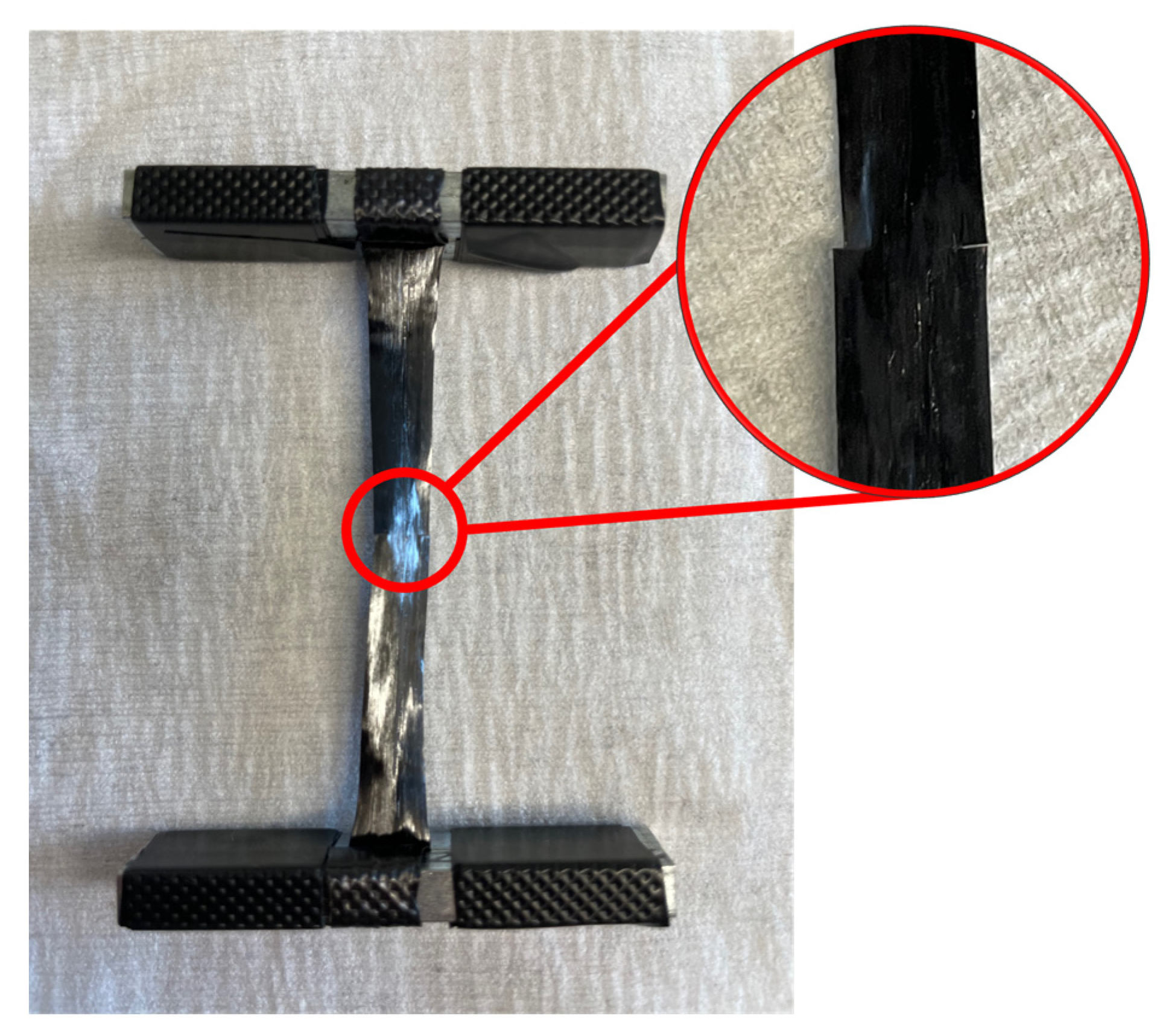
2.1. Tensile Test
2.2. Tensile Test Validation
3. Finite Element Model
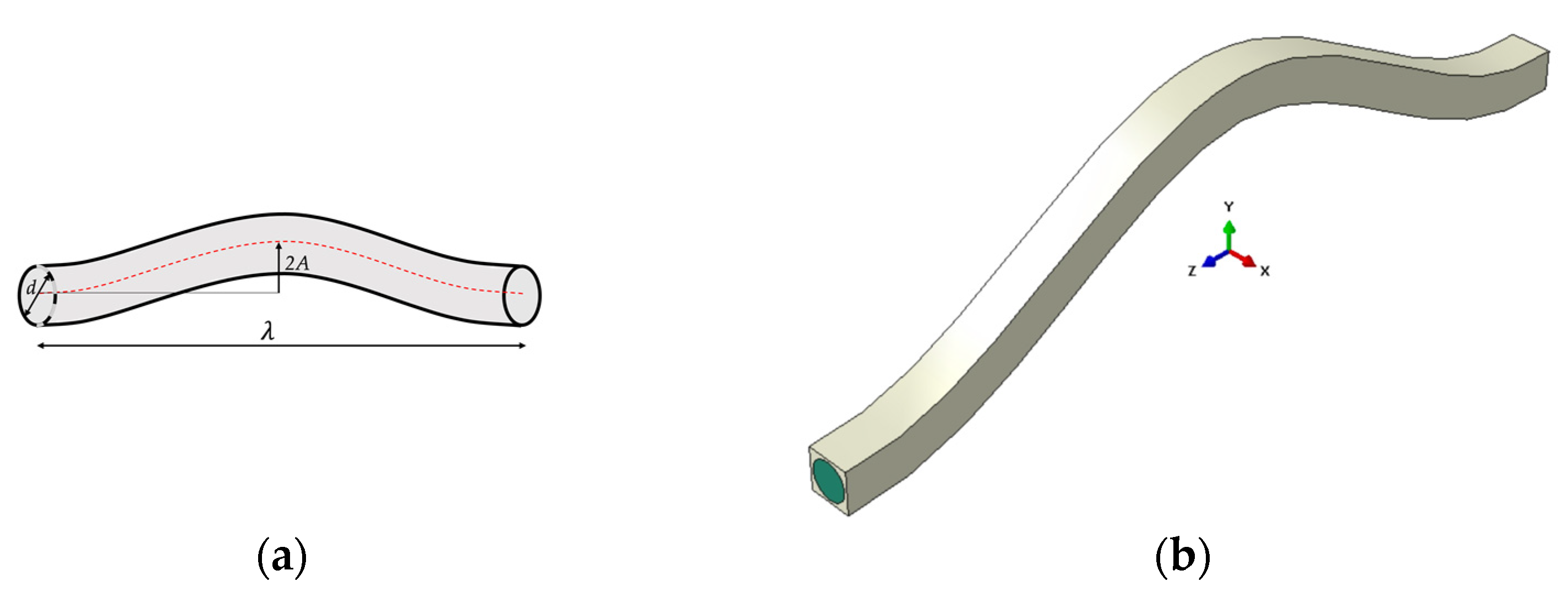
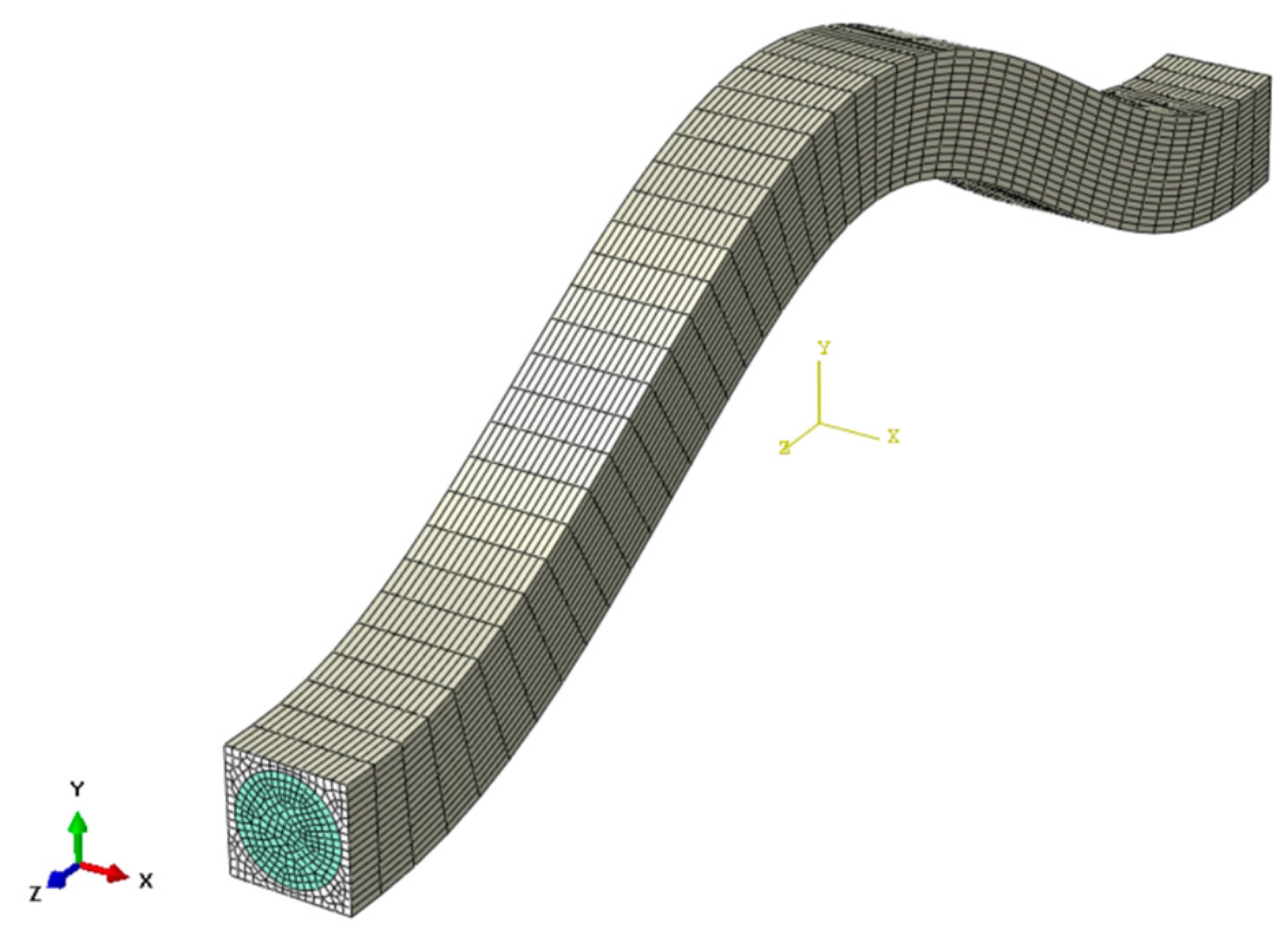
3.1. Create RVE
3.2. Applied Periodic Boundary Conditions
3.3. Homogenization Method
4. Results and Discussion
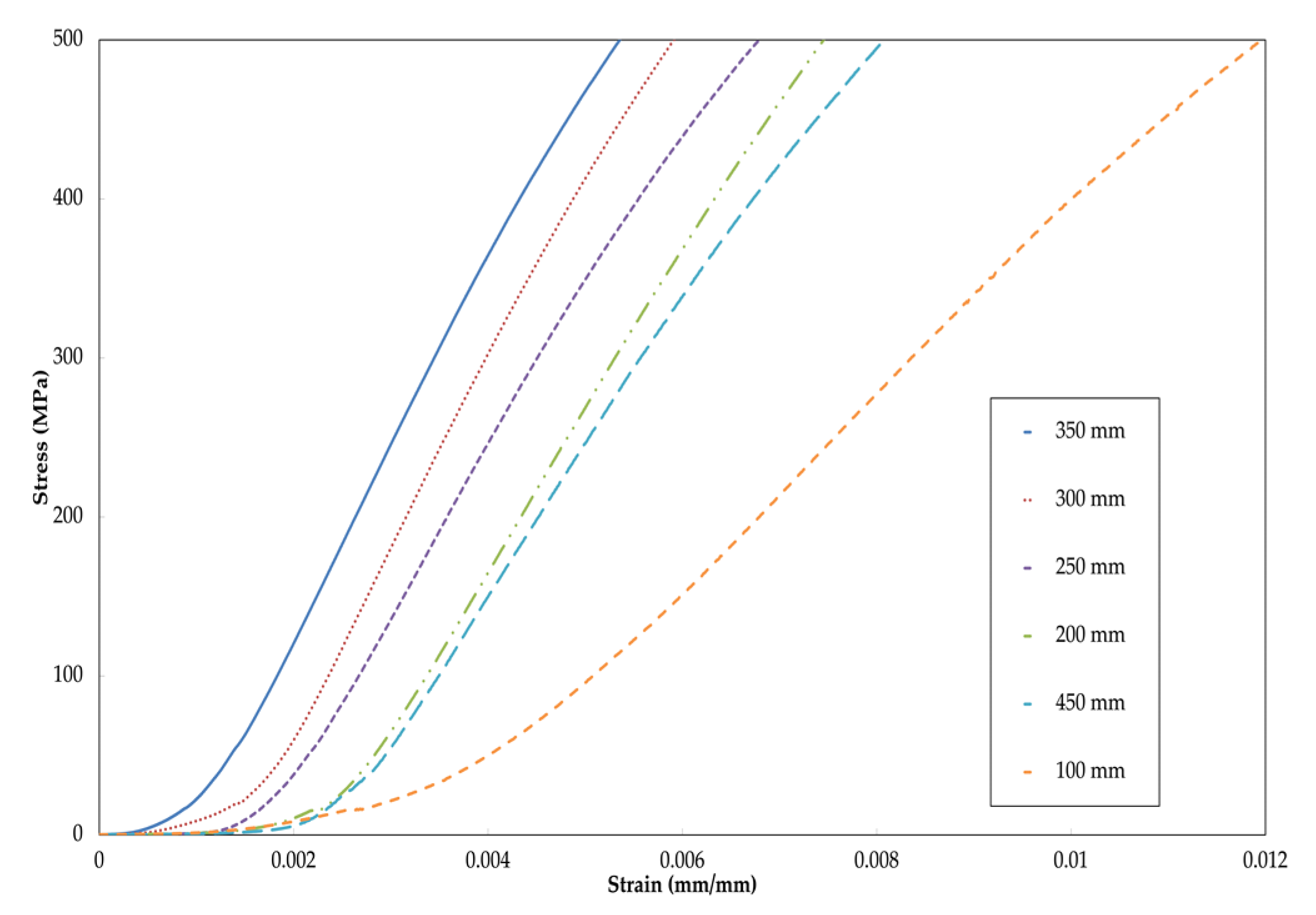
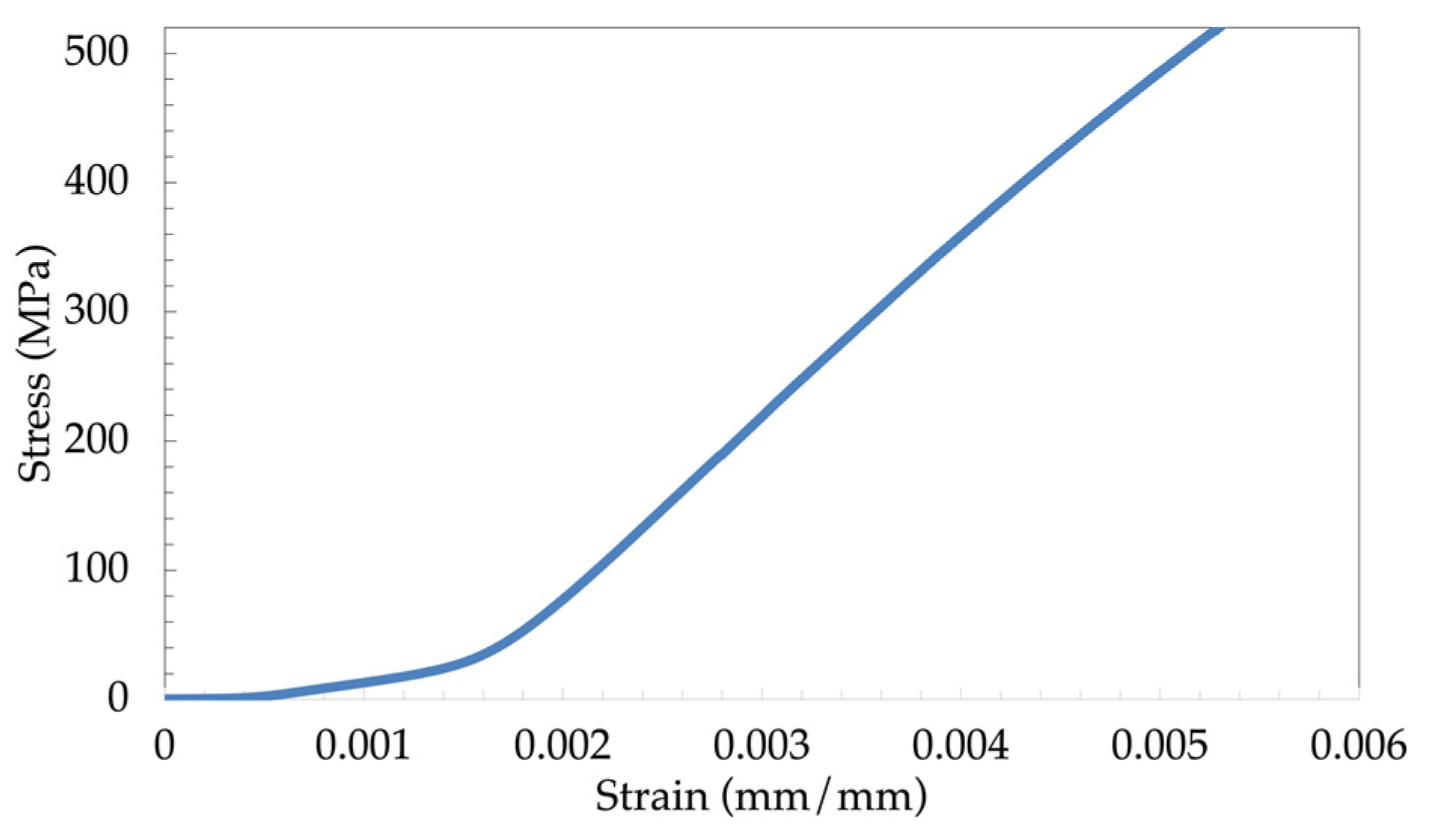
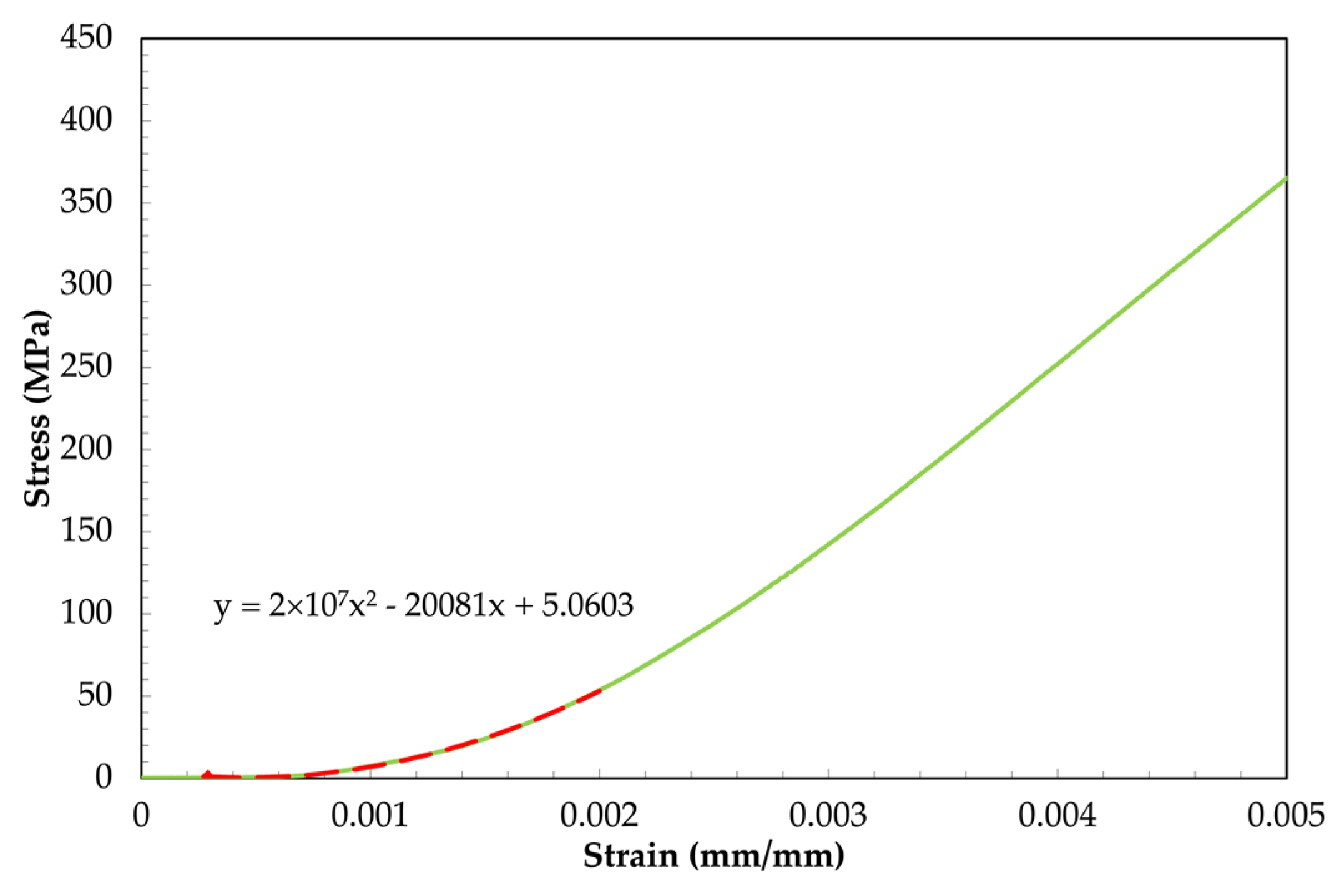
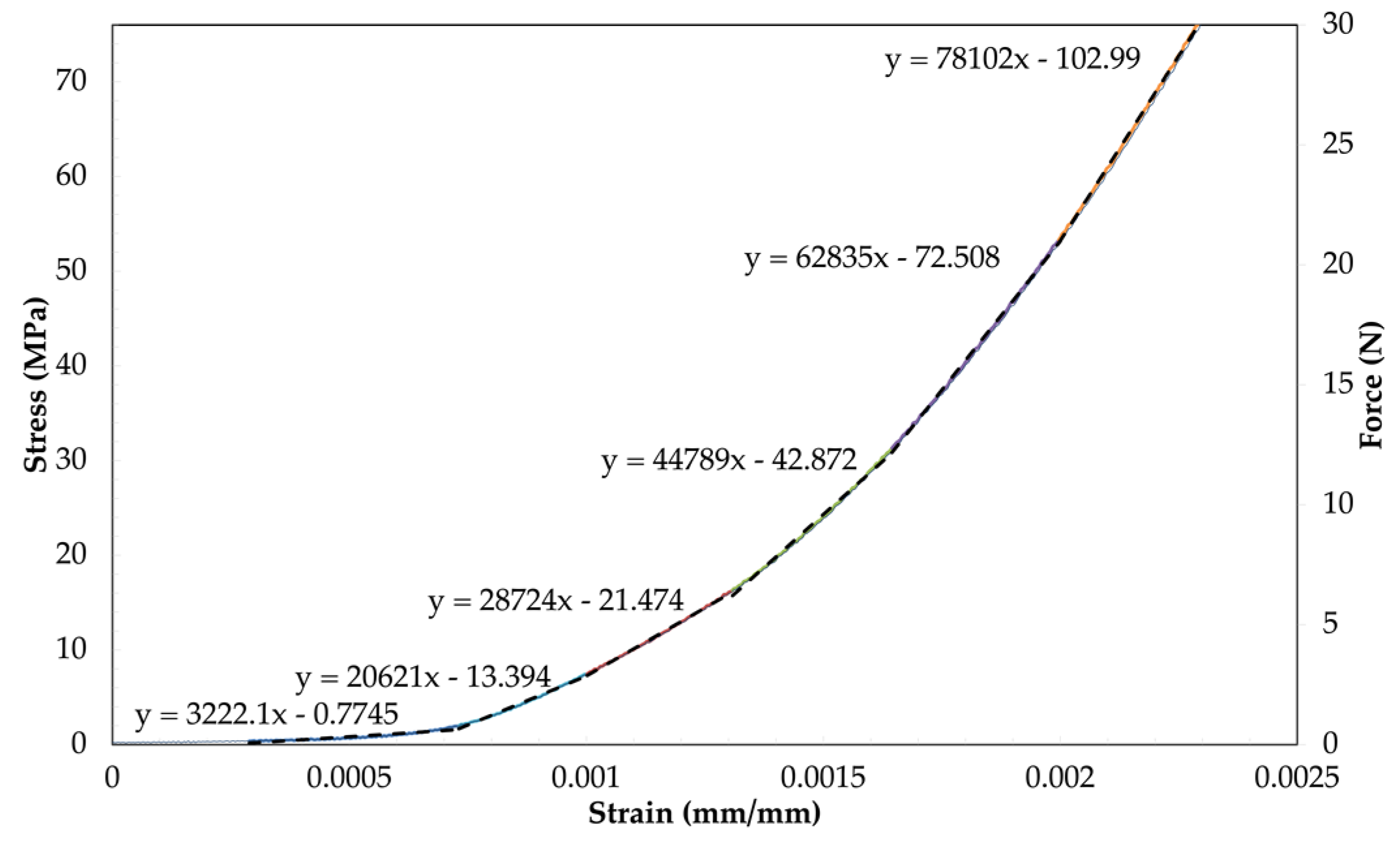
4.1. Experiment Results from Tensile Test
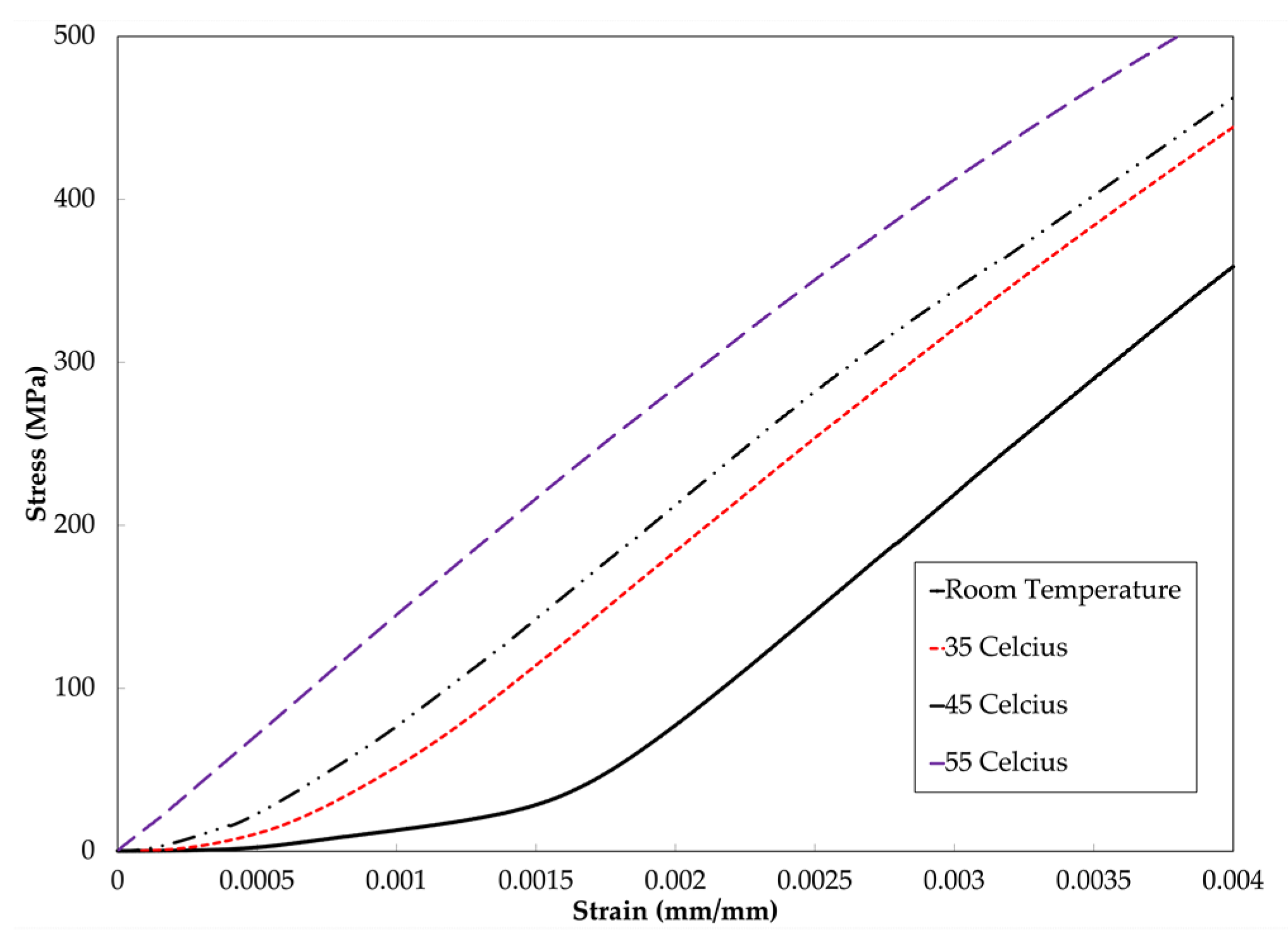
4.2. Effects of Temperature on the Tensile Behavior
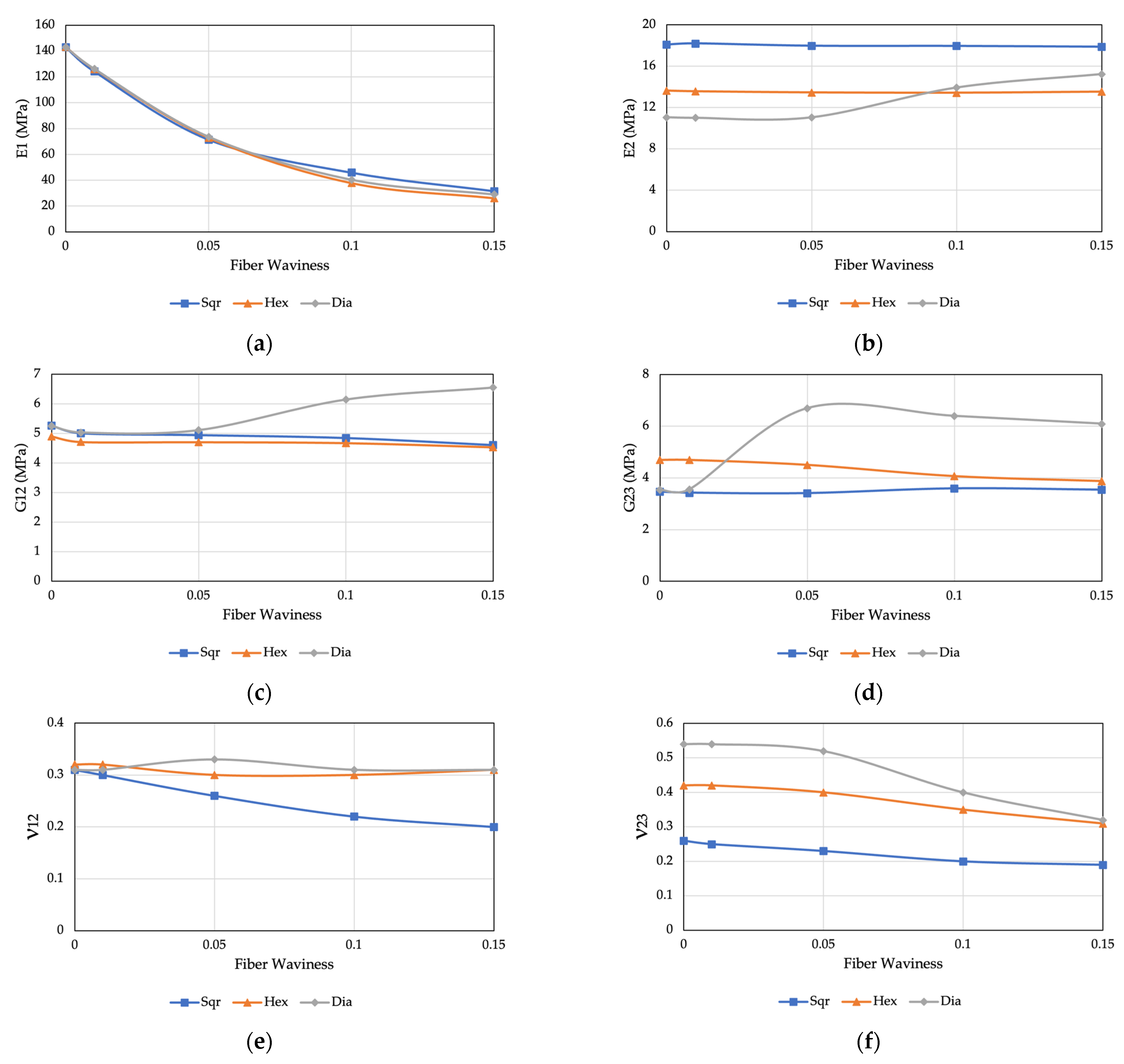
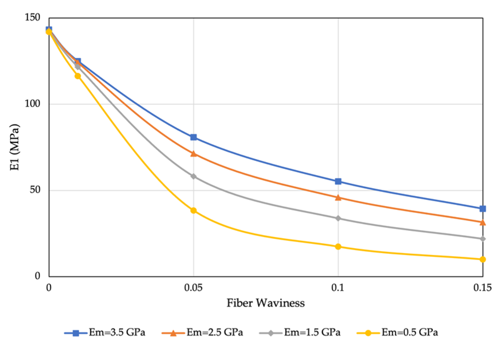
4.3. Finite Element Model
5. Conclusions
Author Contributions
Funding
Data Availability Statement
Acknowledgments
Conflicts of Interest
References
- Dangora, L.M.; Mitchell, C.; White, K.D.; Sherwood, J.A.; Parker, J.C. Characterization of temperature-dependent tensile and flexural rigidities of a cross-ply thermoplastic lamina with implementation into a forming model. Int. J. Mater. Form. 2018, 11, 43–52. [Google Scholar] [CrossRef]
- Rashidi, A.; Montazerian, H.; Yesilcimen, K.; Milani, A.S. Experimental characterization of the inter-ply shear behavior of dry and prepreg woven fabrics: Significance of mixed lubrication mode during thermoset composites processing. Compos. Part Appl. Sci. Manuf. 2020, 129, 105725. [Google Scholar] [CrossRef]
- Kheradpisheh, M.; Hojjati, M. Wrinkle Formation and Initial Defect Sensitivity of Steered Tow in Automated Fiber Placement. J. Compos. Sci. 2021, 5, 295. [Google Scholar] [CrossRef]
- Brasington, A.; Sacco, C.; Halbritter, J.; Wehbe, R.; Harik, R. Automated fiber placement: A review of history, current technologies, and future paths forward. Compos. Part C Open Access 2021, 6, 100182. [Google Scholar] [CrossRef]
- Garnich, M.R.; Karami, G. Localized Fiber Waviness and Implications for Failure in Unidirectional Composites. J. Compos. Mater. 2005, 39, 1225–1245. [Google Scholar] [CrossRef]
- Alshahrani, H.; Hojjati, M. A theoretical model with experimental verification for bending stiffness of thermosetting prepreg during forming process. Compos. Struct. 2017, 166, 136–145. [Google Scholar] [CrossRef]
- Alshahrani, H.; Hojjati, M. Bending behavior of multilayered textile composite prepregs: Experiment and finite element modeling. Mater. Des. 2017, 124, 211–224. [Google Scholar] [CrossRef]
- Le, A.; Nimbalkar, S.; Zobeiry, N.; Malek, S. An efficient multi-scale approach for viscoelastic analysis of woven composites under bending. Compos. Struct. 2022, 292, 115698. [Google Scholar] [CrossRef]
- Rajan, S.; Sutton, M.A.; Wehbe, R.; Gurdal, Z.; Kidane, A.; Emri, I. Characterization of viscoelastic bending stiffness of uncured carbon-epoxy prepreg slit tape. Compos. Struct. 2021, 275, 114295. [Google Scholar] [CrossRef]
- Potter, K.; Langer, C.; Hodgkiss, B.; Lamb, S. Sources of variability in uncured aerospace grade unidirectional carbon fibre epoxy preimpregnate. Compos. Part Appl. Sci. Manuf. 2007, 38, 905–916. [Google Scholar] [CrossRef]
- Potter, K.; Khan, B.; Wisnom, M.; Bell, T.; Stevens, J. Variability, fibre waviness and misalignment in the determination of the properties of composite materials and structures. Compos. Part Appl. Sci. Manuf. 2008, 39, 1343–1354. [Google Scholar] [CrossRef]
- Zhang, W.; Ren, H.; Lu, L.; Zhang, Z.; Su, L.; Wang, Q.J.; Zeng, D.; Su, X.; Cao, J. Experimental Methods to Characterize the Woven Composite Prepreg Behavior during the Preforming Process. In Proceedings of the Thirty-First Technical Conference of the American Society for Composites 2016, Williamsburg, VA, USA, 19–21 September 2016; Available online: https://www.osti.gov/biblio/1431017-experimental-methods-characterize-woven-composite-prepreg-behavior-during-preforming-process (accessed on 29 November 2021).
- Sentis, D.F.; Cochereau, T.; Orgéas, L.; Dumont, P.J.; Rolland du Roscoat, S.; Laurencin, T.; Terrien, M.; Sager, M. Tensile behaviour of uncured sheet moulding compounds: Rheology and flow-induced microstructures. Compos. Part Appl. Sci. Manuf. 2017, 101, 459–470. [Google Scholar] [CrossRef]
- Han, M.-G.; Chang, S.-H. Draping simulations of carbon/epoxy fabric prepregs using a non-orthogonal constitutive model considering bending behavior. Compos. Part Appl. Sci. Manuf. 2021, 148, 106483. [Google Scholar] [CrossRef]
- Rozylo, P.; Falkowicz, K.; Wysmulski, P.; Debski, H.; Pasnik, J.; Kral, J. Experimental-Numerical Failure Analysis of Thin-Walled Composite Columns Using Advanced Damage Models. Materials 2021, 14, 6. [Google Scholar] [CrossRef]
- Wysmulski, P.; Debski, H. The analysis of sensitivity to eccentric load of compressed thin-walled laminate columns. AIP Conf. Proc. 2019, 2078, 020006. [Google Scholar] [CrossRef]
- Wysmulski, P. Non-linear analysis of the postbuckling behaviour of eccentrically compressed composite channel-section columns. Compos. Struct. 2023, 305, 116446. [Google Scholar] [CrossRef]
- Zhou, X.-Y.; Qian, S.-Y.; Wang, N.-W.; Xiong, W.; Wu, W.-Q. A review on stochastic multiscale analysis for FRP composite structures. Compos. Struct. 2022, 284, 115132. [Google Scholar] [CrossRef]
- Erice, B.; Thomson, D. Modelling the Non-linear fibre and matrix dominated compressive behaviour in unidirectional Fibre-reinforced composites. Compos. Struct. 2023, 304, 116396. [Google Scholar] [CrossRef]
- Safdar, N.; Daum, B.; Rolfes, R. A numerical prediction of failure probability under combined compression-shear loading for unidirectional fiber reinforced composites. Mech. Mater. 2022, 171, 104352. [Google Scholar] [CrossRef]
- Yurgartis, S.W. Measurement of small angle fiber misalignments in continuous fiber composites. Compos. Sci. Technol. 1987, 30, 279–293. [Google Scholar] [CrossRef]
- Stewart, A.L.; Poursartip, A. Characterization of fibre alignment in as-received aerospace grade unidirectional prepreg. Compos. Part Appl. Sci. Manuf. 2018, 112, 239–249. [Google Scholar] [CrossRef]
- Wilhelmsson, D.; Asp, L. A high resolution method for characterisation of fibre misalignment angles in composites. Compos. Sci. Technol. 2018, 165, 214–221. [Google Scholar] [CrossRef]
- Joyce, P.J.; Kugler, D.; Moon, T.J. A Technique for Characterizing Process-Induced Fiber Waviness in Unidirectional Composite Laminates-Using Optical Microscopy. J. Compos. Mater. 1997, 31, 1694–1727. [Google Scholar] [CrossRef]
- Herráez, M.; González, C.; Lopes, C.S.; de Villoria, R.G.; LLorca, J.; Varela, T.; Sánchez, J. Computational micromechanics evaluation of the effect of fibre shape on the transverse strength of unidirectional composites: An approach to virtual materials design. Compos. Part Appl. Sci. Manuf. 2016, 91, 484–492. [Google Scholar] [CrossRef]
- Kuksenko, D.; Böhm, H.J.; Drach, B. Effect of micromechanical parameters of composites with wavy fibers on their effective response under large deformations. Adv. Eng. Softw. 2018, 121, 206–222. [Google Scholar] [CrossRef]
- Garnich, M.R.; Karami, G. Finite Element Micromechanics for Stiffness and Strength of Wavy Fiber Composites. J. Compos. Mater. 2004, 38, 273–292. [Google Scholar] [CrossRef]
- Chanda, A.; Sinha, S.K.; Datla, N.V. The influence of fiber alignment, structure and concentration on mechanical behavior of carbon nanofiber/epoxy composites: Experimental and numerical study. Polym. Compos. 2021, 42, 1155–1173. [Google Scholar] [CrossRef]
- Alves, M.P.; Cimini, C.A., Jr.; Ha, S.K. Fiber waviness and its effect on the mechanical performance of fiber reinforced polymer composites: An enhanced review. Compos. Part Appl. Sci. Manuf. 2021, 149, 106526. [Google Scholar] [CrossRef]
- Karami, G.; Garnich, M. Effective moduli and failure considerations for composites with periodic fiber waviness. Compos. Struct. 2005, 67, 461–475. [Google Scholar] [CrossRef]
- Karami, G.; Garnich, M. Micromechanical study of thermoelastic behavior of composites with periodic fiber waviness. Compos. Part B Eng. 2005, 36, 241–248. [Google Scholar] [CrossRef]
- An, N.; Jia, Q.; Jin, H.; Ma, X.; Zhou, J. Multiscale modeling of viscoelastic behavior of unidirectional composite laminates and deployable structures. Mater. Des. 2022, 219, 110754. [Google Scholar] [CrossRef]
- CYCOM 977-2. Solvay. Available online: https://www.solvay.com/en/product/cycom-977-2 (accessed on 29 November 2021).
- Riaño, L.; Joliff, Y. An AbaqusTM plug-in for the geometry generation of Representative Volume Elements with randomly distributed fibers and interphases. Compos. Struct. 2019, 209, 644–651. [Google Scholar] [CrossRef]
- Omairey, S.L.; Dunning, P.D.; Sriramula, S. Development of an ABAQUS plugin tool for periodic RVE homogenisation. Eng. Comput. 2019, 35, 567–577. [Google Scholar] [CrossRef] [Green Version]


| Fiber | Resin | Resin Content (%) | Tow Width (mm) | Tow Thickness (mm) |
|---|---|---|---|---|
| 12K HTS-196 | CYCOM 977-2 | 40 | 6 | 0.2 |
| Gauge Length (mm) | Elastic Modulus (GPa) |
|---|---|
| 100 | 62 |
| 150 | 97 |
| 200 | 101 |
| 250 | 108 |
| 300 | 130 |
| 350 | 130 |
| Loading Case | Calculation of Cij | |
|---|---|---|
| (a) | ||
| (b) | ||
| (c) | ||
| (d) | ||
| (e) | ||
| (f) |
| Sample Number | Linear Tensile Modulus (GPa) |
|---|---|
| Sample 1 | 130 |
| Sample 2 | 140 |
| Sample 3 | 130 |
| Sample 4 | 132 |
| Sample 5 | 136 |
| Sample 6 | 141 |
| Sample 7 | 138 |
| Sample 8 | 135 |
| Section Number | Tensile Range (N) | Average Tensile Modulus (GPa) |
|---|---|---|
| 1 | 1–3 | 20 |
| 2 | 3–6 | 29 |
| 3 | 6–12 | 45 |
| 4 | 12–20 | 63 |
| 5 | 20–30 | 78 |
Disclaimer/Publisher’s Note: The statements, opinions and data contained in all publications are solely those of the individual author(s) and contributor(s) and not of MDPI and/or the editor(s). MDPI and/or the editor(s) disclaim responsibility for any injury to people or property resulting from any ideas, methods, instructions or products referred to in the content. |
© 2023 by the authors. Licensee MDPI, Basel, Switzerland. This article is an open access article distributed under the terms and conditions of the Creative Commons Attribution (CC BY) license (https://creativecommons.org/licenses/by/4.0/).
Share and Cite
Derakhshani Dastjerdi, M.; Carboni, M.; Hojjati, M. Mechanical Properties of Uncured Thermoset Tow Prepreg: Experiment and Finite Element Analysis. J. Compos. Sci. 2023, 7, 312. https://doi.org/10.3390/jcs7080312
Derakhshani Dastjerdi M, Carboni M, Hojjati M. Mechanical Properties of Uncured Thermoset Tow Prepreg: Experiment and Finite Element Analysis. Journal of Composites Science. 2023; 7(8):312. https://doi.org/10.3390/jcs7080312
Chicago/Turabian StyleDerakhshani Dastjerdi, Mina, Massimo Carboni, and Mehdi Hojjati. 2023. "Mechanical Properties of Uncured Thermoset Tow Prepreg: Experiment and Finite Element Analysis" Journal of Composites Science 7, no. 8: 312. https://doi.org/10.3390/jcs7080312